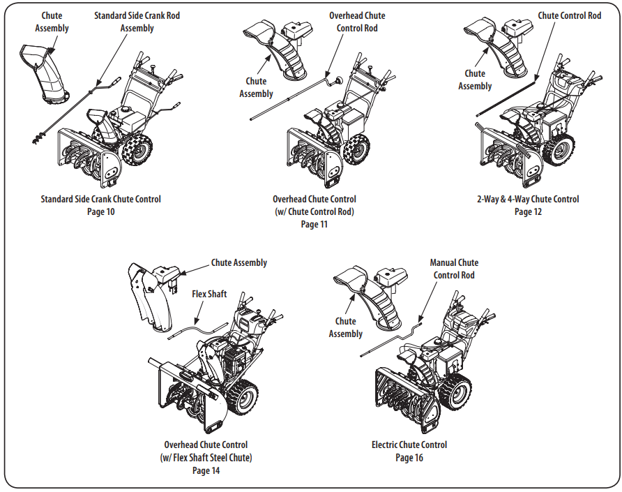
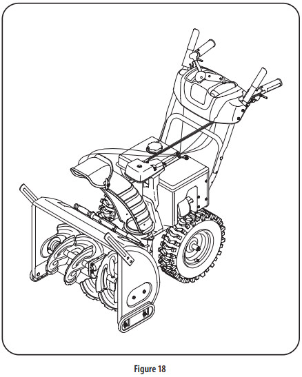
NOTE: This Operator’s Manual covers several models. Features may vary by model. Not all features in this manual are applicable to all models and the model depicted may differ from yours. Refer to Figure 1 which shows the different versions and match the contents of carton (chute and directional control rod/flex shaft) to identify your specific unit.
NOTE: References to right or left side of the snow blower are determined from behind the unit in the operating position (standing directly behind the snow blower, facing the handle panel).
UNPACKING: Removing From Carton
Cut the corners of the carton and lay the sides flat on the ground. Remove and discard all packing inserts.
Move the snow blower out of the carton.
Make certain the carton has been completely emptied before discarding it.
Handle Assembly
Refer to Figure 1 and proceed to your applicable chute style.
1. Cut cable ties securing chute control rod or upper handle to the lower handle (if applicable), set aside the chute control rod (if applicable) and remove the wrap around the handles (if applicable).
NOTE: Do not cut the cable tie securing the cables to the engine for units equipped.
NOTE: On units with Overhead Chute Control, Four-Way Chute Control, and Electric Chute Control cut cable ties securing flex shaft to the lower handle and set the flex shaft aside. Remove rubber bands securing cables to carriage screws and cut cable tie securing shift rod to lower handle. Refer to Figure to help identify your unit.
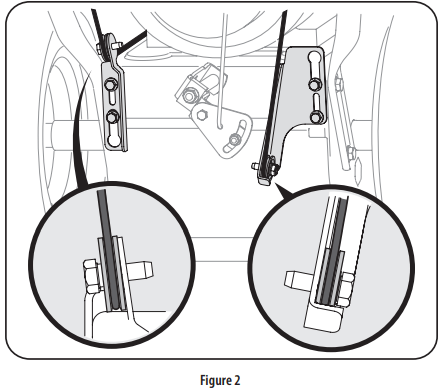
2. Observe the lower rear area of the snow blower to be sure both cables are aligned with roller guides before pivoting the handle upward. See Figure 2.
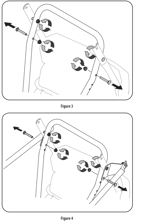
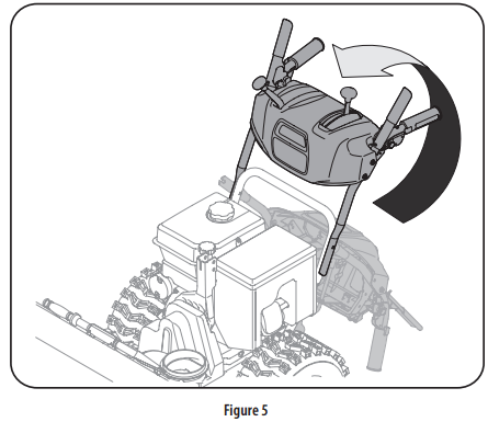
3. Loosen the top two lock nuts securing the upper and lower handle and remove the two carriage screws from the lower handle and set aside. See Figure 3 or Figure 4 for units with side supports.
4. Place shift lever in Forward-6 position or fastest forward speed (if equipped).
5. Pull up and back on upper handle as shown in Figure 5. As you are raising the handle upward, make sure that both ends of the center cable are positioned properly in the brackets. Align upper handle with the lower handle.
NOTE: On select units with steel rod speed selectors, you may need to lower shift rod to the side slightly to maneuver handle panel over it when pivoting handle upward.
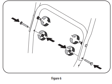
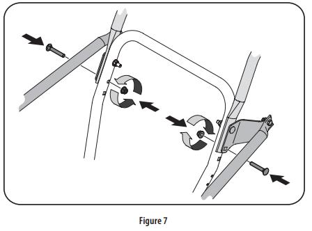
6. Attach the two carriage screws and lock nuts removed in Step 2. Finish securing the handle by tightening the top two lock nuts loosened in Step 2. See Figure 6 or Figure 7 for units with side supports.
7. Remove and discard any rubber bands, if present. They are for packaging purposes only.
8. On units equipped with cable guides on top of the engine, check that all cables are properly routed through the cable guide. Then pull the cables towards the chute and pull the cable tie on the engine snug on the cables to secure in place.
NOTE: For smoothest operation, cables should all be to the left of the chute directional control rod.
STOP: Refer to Figure 1 to identify your applicable chute style and continue to Chute Assembly Options (page 9).
Chute Assembly Options
Refer to Figure 1 and proceed to your applicable Chute Control Style on pages 10-17
Standard Side Crank Chute Control
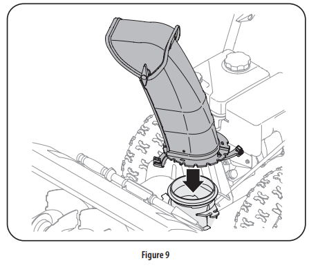
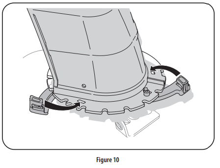
1. Position chute assembly over base. See Figure 9.
2. Close flange keepers to secure chute assembly to chute base. Flange keepers will click into place when properly secure. See “Figure 10”10.
NOTE: Ensure the lower chute is secured to the flange on the chute base. The lower edge of the chute keeper should be positioned below the flange on the chute base after being clicked into place. If flange keepers will not easily click into place, use palm of your hand to apply swift, firm pressure to the back of each.
Chute Directional Control Assembly
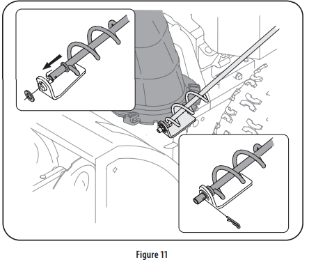
1. Remove plastic cap (if present), flat washer and hairpin clip from end of chute directional control assembly. See Figure 11.
2. Insert end of chute directional control assembly into lower bracket and secure chute directional control assembly with flat washer and hairpin clip removed in Step 1. If necessary, lower bracket can be adjusted. Refer to Chute Bracket Adjustment in Service section on page 32.
Overhead Chute Control (w/ Chute Control Rod)
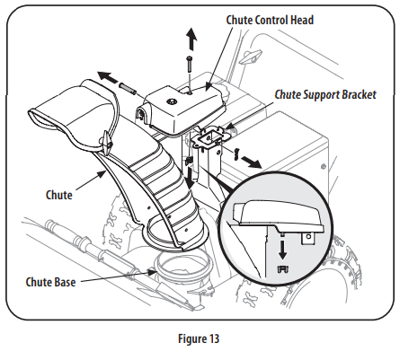
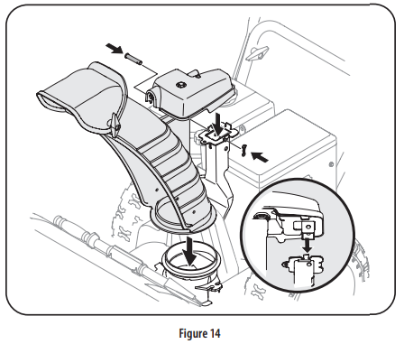
1. Remove wing nut and hex screw from chute control head and clevis pin and cotter pin from chute support bracket. Position chute assembly (forwardfacing) over chute base. See Figure 13.
2. Place chute assembly onto chute base and secure chute control head to chute support bracket with clevis pin and cotter pin removed in Step 1. See Figure 14.
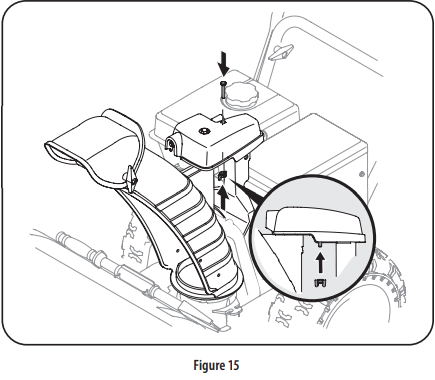
3. Finish securing chute control head to chute support bracket with wing nut (a) and hex screw (b) removed in Step 1. See Figure 15.
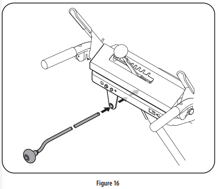
4. Insert chute control rod into the support bracket on rear of the dash panel. See Figure 16.
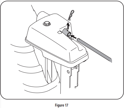
5. Remove hairpin clip (a) from rear of chute control head. See Figure 17.
6. Insert chute control rod (b) into rear of chute control head. See Figure 17. Secure chute control rod to chute control assembly with hairpin clip removed in Step 5.
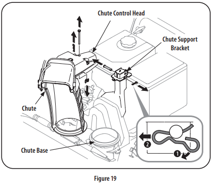
2-Way & 4-Way Chute Control
1. Remove hairpin clip, wing nut and hex screw from chute control head and clevis pin and bow-tie cotter pin from chute support bracket. See Figure 19
NOTE: For smoothest operation, cables should all be to the left of the chute directional control rod.
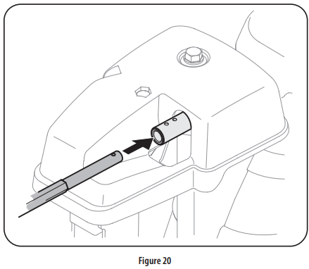
2. Insert chute control rod into chute control head. Push rod as far into chute control head as possible, keeping holes in rod pointing upward. See Figure 20.
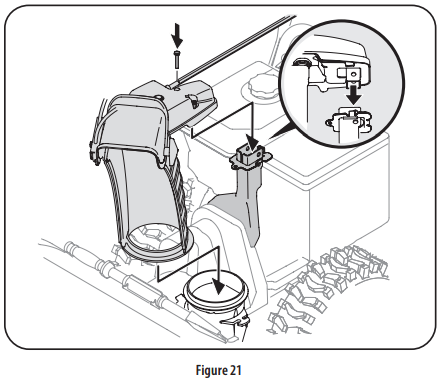
3. Place chute onto chute base and ensure chute control rod is positioned under handle panel. Install hex screw removed in Step 1, but do not secure with wing nut at this time. Figure 21.
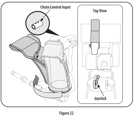
4. Squeeze trigger on joystick and rotate chute by hand to face forward. The holes in chute control input will be facing up. See Figure 22.
NOTE: Chute will not rotate without squeezing trigger on joystick.
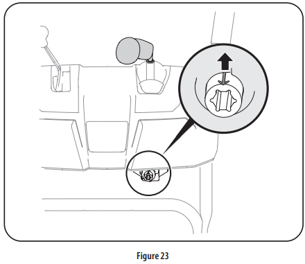
5. Rotate joystick to one o’clock position so that indicator arrow on pinion gear below control panel faces upward. See Figure 23.
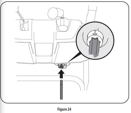
6. Insert chute control rod into pinion gear below joystick. Make sure to line up hole in rod with arrow on pinion gear. See Figure 24
NOTE: Chute control rod will fit snug into pinion gear. Support rear of dash panel with one hand while inserting rod with your other hand to ensure rod is inserted all the way into pinion gear.
NOTE: The hole in the chute directional control rod is a reference for aligning rod with indicator arrow on pinion gear, and will be visible after rod has been inserted.
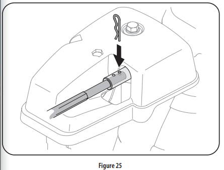
7. Push chute control rod toward control panel until hole in rod lines up with hole in chute control input closest to chute control head and insert hairpin clip (a)removed in Step 1. See Figure 25
NOTE: Second hole is used to achieve further engagement of chute control rod into pinion gear if required. Refer to Service section for Chute Control Rod adjustments.
8. Finish securing chute control head to chute support bracket with wing nut, clevis pin, and bow-tie cotter pin (e) removed in Step 1.
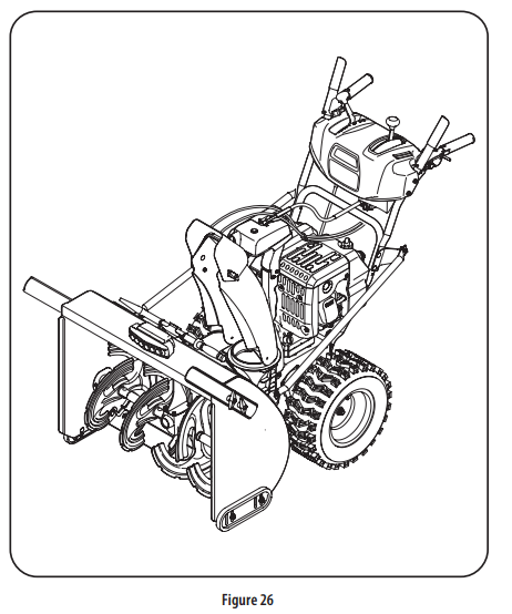
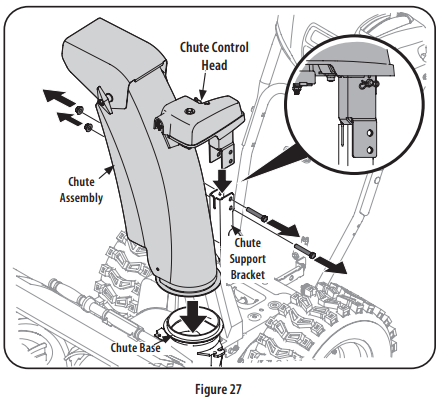
Overhead Chute Control (w/ Flex Shaft & Steel Chute)
1. Remove lock nuts and hex screws from chute support bracket (this will require two wrenches). See Figure 27.
2. Place chute assembly onto chute base and chute control head onto chute support bracket. See Figure 27.
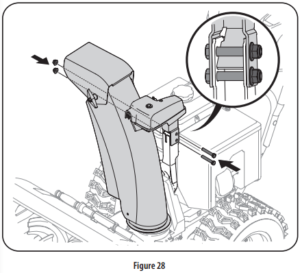
3. Secure chute control head to chute support bracket with lock nuts and hex screws removed in Step 1. See Figure 28
NOTE: For smoothest operation, the cables should all be to the left of the chute control rod.
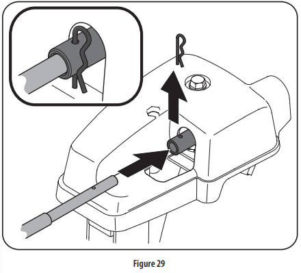
4. Remove hairpin clip from rear of chute control assembly. See Figure 29.
5. Insert flex shaft removed during handle assembly from lower handle into rear of chute directional control head. See Figure 29. Secure flex shaft to chute control head with hairpin clip removed in Step 4.
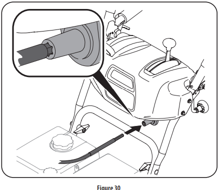
6. Insert hex end of flex shaft into chute control rod coupling under dash panel. See Figure 30.
7. Ensure speed selector is in fastest forward speed.
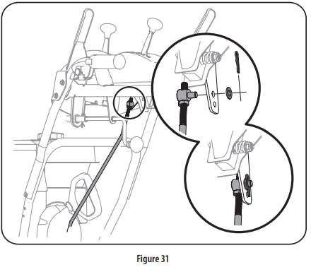
8. Remove cotter pin and washer from ferrule on end of shift rod. See “Figure 31” inset.
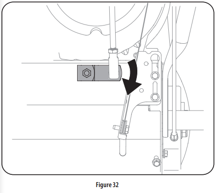
9. Make sure the shift lever on the back of the transmission is rotated downward to the full extent of its rotation. See Figure 32.
10. Insert ferrule into top hole of shift lever and secure with cotter pin (a) and washer (b) removed in Step 8. See Figure 31. Ferrule may need to be adjusted up or down.
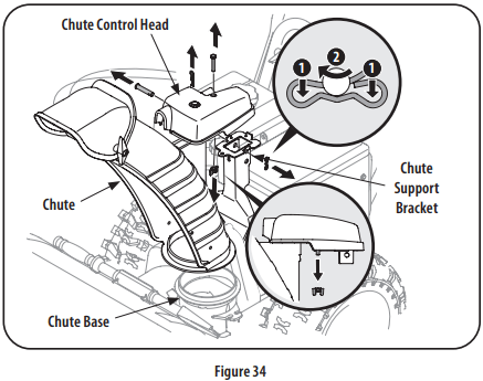
Electric Chute Control
1. Remove cotter pin, wing nut, and hex screw from chute control head and clevis pin and bow-tie cotter pin from chute support bracket. See Figure 34.
NOTE: For smoothest operation, the cables should all be to the left of the chute control rod.
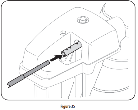
2. Insert the round end of the chute control rod into input of chute control head. Push rod as far into the chute control head as possible, keeping the holes in the rod pointing upward. See Figure 35.
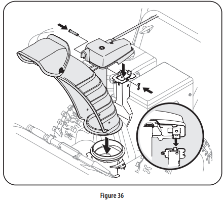
3. Place chute onto chute base and ensure chute control rod is positioned under handle panel. Secure chute control head to chute support bracket with clevis pin and bow-tie cotter pin removed in Step 1. See Figure 36.
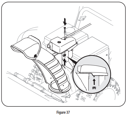
4. Finish securing chute control head by installing hex screw and wing nut removed in Step 2. See Figure 37.
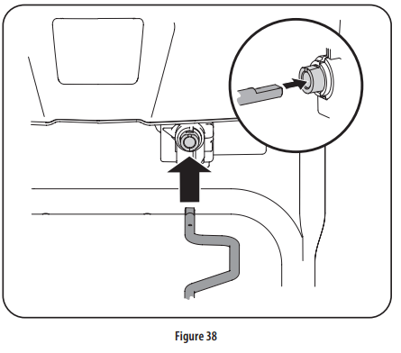
5. Insert the other end of the chute control rod into the input shaft below the handle panel. Make sure to line up the flat end of the rod and the flat end of the input shaft. You may need to rotate the rod around until these two surfaces line up. See Figure 38.
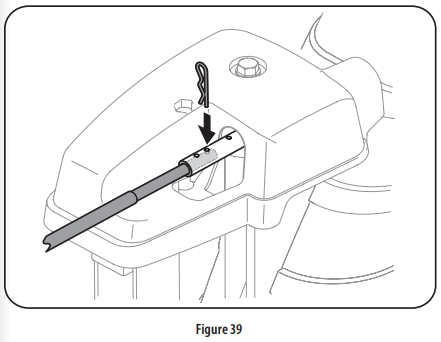
6. Push the chute control rod toward the control panel until the hole in the rod lines up with the middle hole in the chute control input and insert the cotter pin removed in Step 1. See Figure 39.
NOTE: There is a reference hole provided at rear end of control rod to help know when holes are vertical.
NOTE: The hole furthest from the chute control head is used to achieve further engagement of the chute control rod into the input shaft if required. Refer to Page 33 of the Maintenance & Adjustments section for Chute Control Rod adjustment.
The hole closest to the chute control head is used for manual movement of the chute assembly if required. Refer to page 24 of the Operation section.
Set-Up
Chute Control Cable Routing (If Equipped)
For units equipped with 2-way or 4-way chute control joystick, electric chute control and/or chute-pitch controls, ensure control cables are routed properly.
NOTE: For smoothest operation, cables should all be to the left of the chute directional control rod.
NOTE: The number of cables routed through the wire guides will depend on unit model.
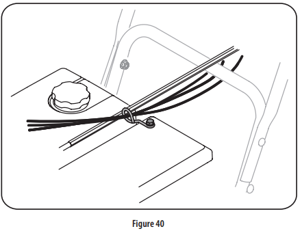
1. Locate cable guide on top of engine and ensure cable(s) are properly routed through the cable guide. See Figure 40
Shear Pins
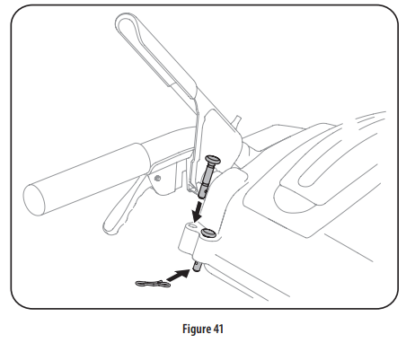
Holes are located in the plastic dash panel for convenient shear pin storage. See Figure 41. Refer to page 16 28 in the Operation section for more information regarding shear pin replacement.
NOTE: If the extra shear pins are not already assembled in the handle panel, they can be found in the manual bag.
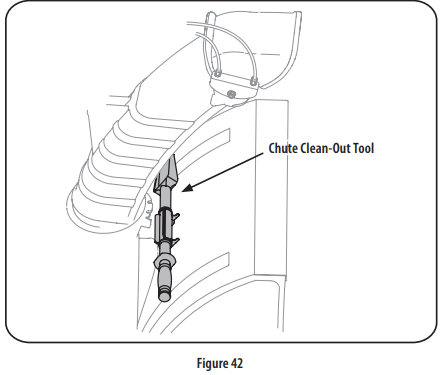
Chute Clean-Out Tool
A chute clean-out tool is fastened to the top of the auger housing with a mounting clip. See Figure 42. The tool is designed to clear a chute assembly of ice and snow. This item is fastened with a cable tie at the factory. Cut the cable tie before operating the snow blower.
WARNING: Never use your hands to clear a clogged chute assembly. Shut OFF engine and remain behind handles until all moving parts have stopped before using the clean-out tool to clear the chute assembly
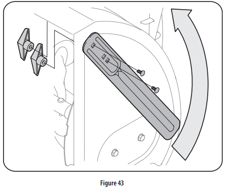
Drift Cutters (if equipped)
Remove the two screws and wing knobs that secure each drift cutter, and remove them from the sides of the auger housing.
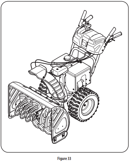
Turn the drift cutters around and position them as shown in Figure 43 to the outside of the auger housing.
Attach the drift cutters with the screws and wing knobs on the outside of the auger housing as shown in Figure 44.
Tire Pressure (If Applicable)
WARNING: Under any circumstance do not exceed manufacturer’s recommended psi. Equal tire pressure should be maintained at all times. Excessive pressure when seating beads may cause tire/rim assembly to burst with force sufficient to cause serious injury. Refer to sidewall of tire for recommended pressure.
The tires are over-inflated for shipping purposes. Check the tire pressure before operating the snow blower. Refer to the tire side wall for tire manufacturer’s recommended psi and deflate (or inflate) the tires as necessary.
NOTE: Equal tire pressure is to be maintained at all times for performance purposes.
Adjustments
Skid Shoes
The snow blower skid shoes are adjusted at the factory to be approx 1/8” below the bottom surface of the shave plate. Adjust them downward, if desired, prior to operating the snow blower.
CAUTION: It is not recommended that you operate this snow blower on gravel as it can easily pick up and throw loose gravel, causing personal injury or damage to the snow blower and surrounding property
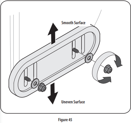
For close snow removal on a smooth surface, raise skid shoes higher on the auger housing. Refer to Figure 45.
Use a middle or lower position when the area to be cleared is uneven, such as a gravel driveway.
NOTE: If you choose to operate the snow blower on a gravel surface, keep the skid shoes in position for maximum clearance between the ground and the shave plate.
To adjust the skid shoes:
Loosen the four hex nuts (two on each side), flat washers, and carriage bolts. Move skid shoes to desired position. See Figure 45.
Make certain the entire bottom surface of skid shoe is against the ground to avoid uneven wear on the skid shoes.
Retighten nuts, washers, and bolts securely.
NOTE: The skid shoes on your unit may look slightly different (and have different hardware) than ones shown in Figure 45.
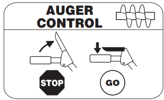
Auger Control
WARNING: Prior to operating your snow blower, carefully read and follow all instructions below. Perform all adjustments to verify your snow blower is operating safely and properly.
Check the adjustment of the auger control as follows:
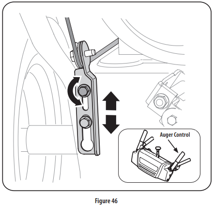
The auger control is located on the left handle. See Figure 46 inset. When the auger control is released and in the disengaged “UP” position, the cable should have very little slack. It should NOT be tight.
In a well-ventilated area, start the snow blower engine as instructed in Starting Engine on page 25-26 in the Operation section of this manual.
While standing in the operator’s position (behind the snow blower), engage the auger.
Allow the auger to remain engaged for approximately ten seconds before releasing the auger control. Repeat this several times.
With the auger control in the disengaged “UP” position, walk to the front of the machine.
Confirm that the auger has completely stopped rotating and shows NO signs of motion. If the auger shows ANY signs of rotating, immediately return to the operator’s position and shut OFF the engine. Wait for ALL moving parts to stop before adjusting the auger control.
To readjust the control cable, loosen the upper hex bolt on the auger cable bracket. See Figure 46.
Position the bracket upward to provide more slack (or downward to increase cable tension).
Retighten the upper hex bolt.
Repeat Step 2 through Step 6 above to verify proper adjustment has been achieved.
OPERATION
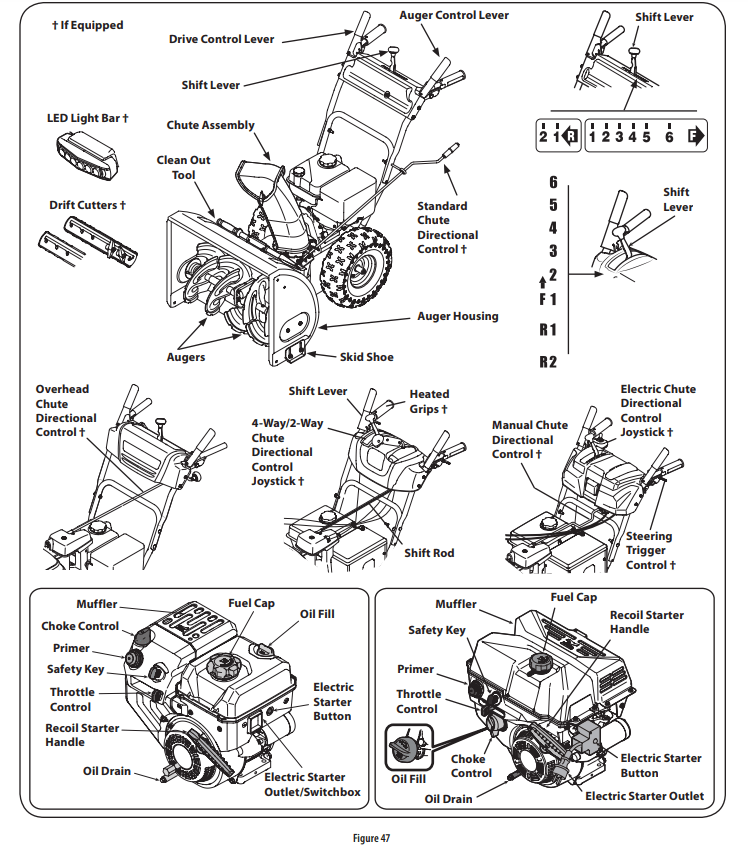
Now that you have set up your snow blower, it’s important to become acquainted with its controls and features. Refer to Figure 47.
NOTE: This Operator’s Manual covers several models. Snow blower features may vary by model. Not all features in this manual are applicable to all snow blower models and the snow blower depicted may differ from yours.
NOTE: All references to the left or right side of the snow blower are from the operator’s position. Any exceptions will be noted.
Shift Lever
The shift lever is located on the right side of the handle panel. Place the shift lever into any of eight positions to control the direction of travel and ground speed.
Forward
Your snow blower has six forward (F) speeds. Position one (1) is the slowest and position six (6) is the fastest.
Reverse
Your snow blower has two reverse (R) speeds. Position one (1) is the slower and position two (2) is the faster.
Drift Cutters (If Equipped)
The drift cutters are designed for use in deep snow. Their use is optional for normal snow conditions. Maneuver the snow blower so that the cutters penetrate a high standing snow drift to assist snow falling into the augers for throwing.
Safety Key
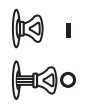
The safety key is a safety device. It must be fully inserted in order for the engine to start. Remove the safety key when the snow blower is not in use.
NOTE: Do not turn the safety key in an attempt to start the engine. Doing so may cause it to break.
Choke Control
The choke control is found on the rear of the engine and is activated by turning the rotary choke knob to the CHOKE position. Activating the choke control closes the choke plate on the carburetor and aids in starting the engine.
Recoil Starter Handle
This handle is used to manually start the engine.
LED Light (If Equipped)
The LED light is located inside of the handle panel and is ON when the engine is running.
LED Light Bar (If Equipped)
The LED headlight is located on top of the auger housing and is automatically turned ON when the engine is started.
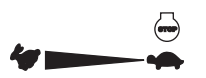
Throttle Control
The throttle control is located on the rear of the engine. It regulates the speed of the engine and will shut off the engine when moved into the STOP position.
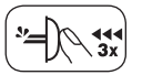
Primer
Depressing the primer forces fuel directly into the engine’s carburetor to aid in cold-weather starting.
Electric Starter Button (If Equipped)
Pressing the electric starter button engages the engine’s electric starter when plugged into a 120V power source.
Electric Starter Outlet (If Equipped)
Requires the use of a three-prong outdoor extension cord and a 120V power source/ wall outlet.
Oil Fill
Engine oil level can be checked and oil added through the oil fill.
Fuel Cap
Unthread the fuel cap to add gasoline to the fuel tank.
Auger
When engaged, the auger blades rotate and draw snow into the auger housing.
Chute Assembly
Snow drawn into the auger housing is discharged out the chute assembly.
Skid Shoes
Position the skid shoes based on surface conditions. Adjust upward for hard-packed snow. Adjust downward when operating on gravel or crushed rock surfaces.
Wheel Steering Controls (If Equipped)
The left and right wheel steering controls are located on the underside of the handles. Squeeze the right control to turn right; squeeze the left control to turn left.
NOTE: Operate the snow blower in open areas until you are familiar with these controls.
Auger Control
The auger control is located on the left handle. Squeeze the control grip against the handle to engage the auger and start snow throwing action. Release to stop.
IMPORTANT: Refer to the Auger Control information in the Assembly & Set-Up section prior to operating your snow blower. Read and follow all instructions carefully and perform all adjustments to verify your snow blower is operating safely and properly
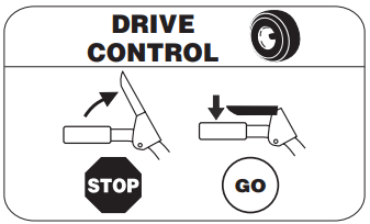
Drive Control/ Auger Control Lock*
The drive control is located on the right handle. Squeeze the control grip against the handle to engage the wheel drive. Release to stop.
*On select models, the drive control also locks the auger control so you can operate the chute directional control without interrupting the snow throwing process. If the auger control is engaged simultaneously with the drive control, the operator can release the auger control (on the left handle) and the augers will remain engaged. Release both controls to stop the augers and wheel drive.
NOTE: Always release the drive control before changing speeds. Failure to do so will result in increased wear on your machine’s drive system.
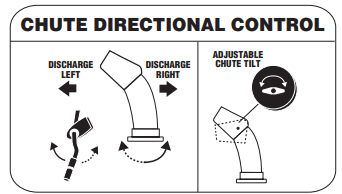
Overhead Chute Directional Control (If Equipped)
The overhead chute directional control is located in the center of the snow blower between the handle panel and lower handle. To change the direction in which snow is thrown, rotate the chute directional control.
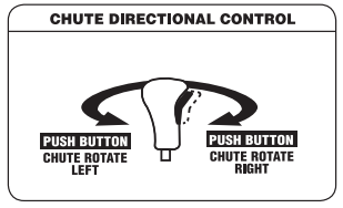
Two-Way Chute Control (If Equipped)
The two-way chute control (Joystick) is located on the left side of the handle panel.
To change the direction in which snow is thrown, squeeze the button on the chute control lever and pivot the chute control lever to the right or to the left.
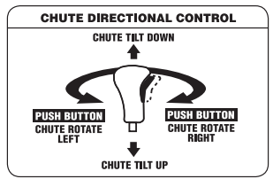
Four-Way Chute Control (Joystick) (If Equipped)
The four-way chute control™ (joystick) is located on the left side of the handle panel.
To change the direction in which snow is thrown, squeeze the button on the chute control lever and pivot the chute control lever to the right or to the left.
To change the angle/distance which snow is thrown, pivot the chute control lever forward to tilt the chute down and backward to tilt the chute up
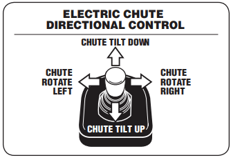
Electric Chute Control Joystick (If Equipped)
The electric chute control (joystick) is located on the right side of the handle panel.
To change the direction in which snow is thrown, move the joystick to the right or to the left.
To change the angle/distance which snow is thrown, pivot the joystick forward to tilt the chute down and backward to tilt the chute up
Manual Chute Control (Units with Electric Chute Directional Control Joystick)
Follow this procedure to manually change the chute direction on units equipped with an electric chute directional control joystick and manual chute directional control rod only. See Figure 47.
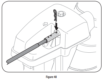
1. Remove the cotter pin from either of the holes furthest from the chute assembly on the chute control head.
2. Push in the chute control rod until the hole in it lines up with the third hole in the chute control head. See Figure 48.
3. Reinsert the cotter pin through this hole and the chute control rod as shown in Figure 48.
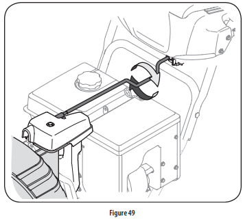
4. Grasp the indented portion of the chute control rod and manually rotate the chute to the right or to the left. See Figure 49.
Clean-Out Tool
WARNING: Never use your hands to clear a clogged chute assembly. Shut off engine and remain behind handles until all moving parts have stopped before using the clean-out tool to clear the chute assembly.
The chute clean-out tool is conveniently fastened to the rear of the auger housing with a mounting clip. Should snow and ice become lodged in the chute assembly during operation, proceed as follows to safely clean the chute assembly and chute opening:
Release both the Auger Control and the Drive Control.
Stop the engine by removing the ignition key.
Remove the clean-out tool from the clip which secures it to the rear of the auger housing.
Use the shovel-shaped end of the clean-out tool to dislodge and scoop any snow and ice which has formed in and near the chute assembly.
Refasten the clean-out tool to the mounting clip on the rear of the auger housing, reinsert the ignition key and start the snow blower’s engine.
While standing in the operator’s position (behind the snow blower), engage the auger control for a few seconds to clear any remaining snow and ice from the chute assembly
Before Starting Engine
WARNING: Read, understand, and follow all instructions and warnings on the machine and in this manual before operating.
Oil :The unit was shipped with oil in the engine. Check oil level before each operation to ensure adequate oil in the engine.
NOTE: Be sure to check the engine on a level surface with the engine stopped.
Remove the oil filler cap/dipstick and wipe the dipstick clean.
Insert the cap/dipstick into the oil filler neck, but do NOT screw it in.
Remove the oil filler cap/dipstick. If the level is low, slowly add oil (5W-30, with a minimum classification of SF/SG) until oil level registers between high (H) and low (L). NOTE: Do not overfill. Overfilling with oil may result in engine smoking, hard starting or spark plug fouling.
Replace and tighten cap/dipstick firmly before starting engine.
Gasoline
Use automotive gasoline (unleaded or low leaded to minimize combustion chamber deposits) with a minimum of 87 octane. Gasoline with up to 10% ethanol or 15% MTBE (Methyl Tertiary Butyl Ether) can be used. Never use an oil/gasoline mixture or dirty gasoline. Avoid getting dirt, dust, or water in the fuel tank. DO NOT use E85 gasoline.
Refuel in a well-ventilated area with the engine stopped. Do not smoke or allow flames or sparks in the area where the engine is refueled or where gasoline is stored.
Do not overfill the fuel tank. After refueling, make sure the tank cap is closed properly and securely.
Be careful not to spill fuel when refueling. Spilled fuel or fuel vapor may ignite. If any fuel is spilled, make sure the area is dry before starting the engine.
Avoid repeated or prolonged contact with skin or breathing of vapor.
WARNING: Use extreme care when handling gasoline. Gasoline is extremely flammable and the vapors are explosive. Never fuel the machine indoors or while the engine is hot or running. Extinguish cigarettes, cigars, pipes and other sources of ignition.
Clean around fuel fill before removing cap to fuel.
Fill tank until fuel reaches 1⁄2 inch below the bottom of the filler neck to allow space for fuel expansion. Be careful not to overfill.
Starting The Engine
WARNING: Always keep hands and feet clear of moving parts. Do not use a pressurized starting fluid. Vapors are flammable.
NOTE: Allow the engine to warm up for a few minutes after starting. The engine will not develop full power until it reaches operating temperatures.
Make certain both the auger control and drive control are in the disengaged (released) position.
Insert key into slot. Make sure it snaps into place. Do not attempt to turn the key.
NOTE: The engine cannot start without the key fully inserted into the ignition switch.
Electric Starter
WARNING: The electric starter is equipped with a grounded three-wire power plug, and is designed to operate on 120 volt AC household current. It must be used with a properly grounded three-prong receptacle at all times to avoid the possibility of electric shock. Follow all instructions carefully prior to operating the electric starter. DO NOT use electric starter in the rain.
Determine that your home’s wiring is a three-wire grounded system. Ask a licensed electrician if you are not certain. If you have a grounded three-prong receptacle, proceed as follows.
If you do not have the proper house wiring, DO NOT use the electric starter under any conditions.
Plug an extension cord into the outlet located on the engine’s surface. Plug the other end of extension cord into a three-prong 120-volt, grounded, AC outlet in a well-ventilated area. CAUTION: The extension cord can be any length, but must be rated for 15 amps at 125 volts, grounded and rated for outdoor use.
Move throttle control to FAST (rabbit) position.
Move choke to the CHOKE position (cold engine start). If engine is warm, place choke in RUN position.
Push primer three (3) times, making sure to cover vent hole in primer bulb when pushing. If engine is warm, push primer only once. Always cover vent hole when pushing. Cool weather may require priming to be repeated.
Push starter button to start engine. Once the engine starts, immediately release starter button. Electric starter is equipped with thermal overload protection; system will temporarily shut-down to allow starter to cool if electric starter becomes overloaded.
As the engine warms, slowly rotate the choke control to RUN position. If the engine falters, restart engine and run with choke at half-choke position for a short period of time, and then slowly rotate the choke into RUN position.
After engine is running, disconnect extension cord from electric starter. When disconnecting, always unplug the end at the wall outlet before unplugging the opposite end from the engine.
Recoil Starter
CAUTION: Do not pull the starter handle while the engine running.
Move throttle control to FAST (rabbit) position.
Move choke to the CHOKE position (cold engine start). If engine is warm, place choke in RUN position.
Push primer three (3) times, making sure to cover vent hole when pushing. If engine is warm, push primer only once. Always cover vent hole when pushing. Cool weather may require priming to be repeated.
Pull gently on the starter handle until it begins to resist, then pull quickly and forcefully to overcome the compression. Do not release the handle and allow it to snap back. Return rope SLOWLY to original position. If required, repeat this step WARNING: Keep a firm grip on the starter cord handle to prevent rapid retraction of starter cord (kickback). Rapid retraction can pull hand and arm toward engine faster than you can let go, and result in broken bones, fractures, bruises or sprains.
As the engine warms, slowly rotate the choke control to RUN position. If the engine falters, restart engine and run with choke at half-choke position for a short period of time, and then slowly rotate the choke into RUN position.
WARNING: To avoid unsupervised engine operation, never leave the machine unattended with the engine running. Turn the engine off after use and remove key.
Stopping The Engine
After you have finished snow-throwing, run engine for a few minutes before stopping to help dry off any moisture on the engine.
Move throttle control to OFF position.
Remove the key. Removing the key will reduce the possibility of unauthorized starting of the engine while equipment is not in use. Keep the key in a safe place. The engine cannot start without the key.
Wipe any moisture away from the controls on the engine.
To Engage Drive
With the throttle control in the Fast (rabbit) position, move shift lever into one of the six forward (F) positions or two reverse (R) positions. Select a speed appropriate for the snow conditions and a pace you’re comfortable with. NOTE: When selecting a Drive Speed, use the slower speeds until you are comfortable and familiar with the operation of the snow blower.
Squeeze the drive control against the handle and the snow blower will move. Release it and drive motion will stop. NOTE: NEVER reposition the shift lever (change speeds or direction of travel) without first releasing the drive control and bringing the snow blower to a complete stop. Doing so will result in premature wear to the snow blower’s drive system.
To Engage Auger
To engage the auger and start throwing snow, squeeze the auger control against the left handle. Release to stop the auger.
Replacing Shear Pins
WARNING: NEVER replace the auger shear pins with anything other than OEM Part No. 738-04124A (gold colored replacement shear pins) or OEM Part No. 738-05273 (Black colored replacement shear pins). Any damage to the auger gearbox or other components as a result of failing to do so will NOT be covered by your snow blower’s warranty.
WARNING: Always turn off the snow blower’s engine and remove the key prior to replacing shear pins.
Each auger blade is secured to the spiral shaft with a shear pin and bow-tie clip. If an auger blade strikes a foreign object or ice jam, the pin will shear off to prevent damage to the blade. If an auger blade does not turn, check to see if its pin has sheared off.
IMPORTANT: ALWAYS use the correct OEM replacement shear pin.
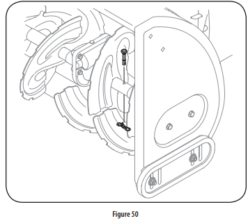
2-Stage Snow Blowers
The auger is secured to the spiral shaft using gold colored shear pins (Sears OEM Part No. 738-04124A). See Figure 50.
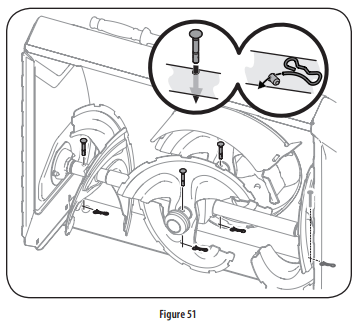
3-Stage Snow Blowers
The side augers and central accelerator auger are secured to the spiral shaft using black shear pins (OEM Part No. 738-05273). See Figure 51.
Using Snow Blower to Clear Snow
WARNING: Check the area to be cleared for foreign objects. Remove foreign objects, if any
Start the engine following starting instructions.
Allow the engine to warm up for a few minutes as the engine will not develop full power until it reaches operating temperature.
Rotate the chute assembly to the desired direction, away from bystanders and/or buildings.
Making certain no bystanders or obstacles are in front of the unit, squeeze the auger control completely against the upper handle to fully engage the auger.
While the auger control is engaged, squeeze the drive control completely against the upper handle to engage the wheels. Do not “feather” the drive control.
As the snow blower starts to move, maintain a firm hold on the handle, and guide the snow blower along the path to be cleared.
Release the auger and drive controls to stop the snow throwing action and forward motion. NOTE: Your unit is equipped with a clutch in the transmission. If the wheels stop turning while trying to discharge large volumes of snow, immediately disengage the drive control and allow the rotating auger to discharge snow from the housing. Reduce the clearing width and continue operation.
On each succeeding pass, readjust the chute assembly to the desired position and slightly overlap the previously cleared path.
SERVICE AND MAINTENANCE
MAINTENANCE SCHEDULE
WARNING: Before performing any type of maintenance/service, disengage all controls and stop the engine. Wait until all moving parts have come to a complete stop. Disconnect spark plug wire and ground it against the engine to prevent unintended starting.
Follow the maintenance schedule given below. This chart describes service guidelines only. Use the Service Log column to keep track of completed maintenance tasks. To locate the nearest Sears Service Center or to schedule service, call the following toll free number:1-888-331-4569.
Interval
Item
Service
Service Log
Each Use and every 5 hours
Engine oil level
Loose or missing hardware
Unit and engine
Check
Tighten or replace
Clean
1st 5 hours
Engine oil
Change
Annually or 25 hours
Spark plug
Control linkages and pivots
Wheels
Gear shaft and Auger shaft
4-Way Chute Control
Check
Lube with light oil
Lube with multipurpose auto grease
Lube with light oil
Check for cable slackness
Annually or 50 hours
Engine oil
Change
Annually or 100 hours
Spark plug
Change
Before Storage
Fuel system
Run engine until it stops from lack of fuel
Engine Maintenance
Checking Engine Oil
WARNING: Before lubricating, repairing, or inspecting, disengage all controls and stop engine. Wait until all moving parts have come to a complete stop.
NOTE: Check the oil level before each use to be sure correct oil level is maintained.
NOTE: 208cc and 243cc engines use 600 ml (approx. 20 oz.). NOTE: 277cc, 357 and 420cc engines use 1100 ml (approx. 37.2 oz).
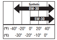
When adding oil to the engine, refer to viscosity chart below. Do not over-fill. Use a 4-stroke, or an equivalent high detergent, premium quality motor oil certified to meet or exceed U.S. automobile manufacturer’s requirements for service classification SG, SF. Motor oils classified SG, SF will show this designation on the container.
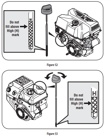
Remove the oil filler cap/dipstick and wipe the dipstick clean.
Insert the cap/dipstick into the oil filler neck, but do NOT screw it in.
Remove the oil filler cap/dipstick. If level is low, slowly add oil until oil level registers between high (H) and low (L). See Figure 52 or Figure 53.
Replace and tighten cap/dipstick firmly before starting engine.
Changing Engine Oil
NOTE: Change the engine oil after the first 5 hours of operation and once a season or every 50 hours thereafter.
Drain fuel from tank by running engine until the fuel tank is empty. Be sure fuel fill cap is secure.
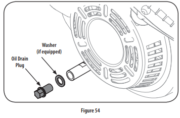
Place suitable oil collection container under oil drain plug.
Remove oil drain plug and washer (if equipped). See 54.
Tip unit to drain oil into the container. Used oil must be disposed of at a proper collection center. CAUTION Used oil is a hazardous waste product. Dispose of used oil properly. Do not discard with household waste. Check with your local authorities or Sears Service Center for safe disposal/recycling facilities.
Reinstall the drain plug and washer (if equipped) and tighten it securely.
Refill with the recommended oil and check the oil level. See Recommended Oil Usage chart.
NOTE: 208cc and 243cc engines use 600 ml (approx. 20 oz.).
NOTE: 277cc, 357 and 420cc engines use 1100 ml (approx. 37.2 oz).
CAUTION: DO NOT use nondetergent oil or 2-stroke engine oil. It could shorten the engine’s service life.
7. Reinstall the oil filler cap/dipstick securely.
CAUTION: Thoroughly wash your hands with soap and water as soon as possible after handling used oil.
Checking Spark Plug
WARNING: DO NOT check for spark with spark plug removed. DO NOT crank engine with spark plug removed.
WARNING: If the engine has been running, the muffler will be very hot. Be careful not to touch the muffler.
NOTE: Check the spark plug once a season or every 25 hours of operation. Change the spark plug once a season or every 100 hours. To ensure proper engine operation, the spark plug must be properly gapped and free of deposits.
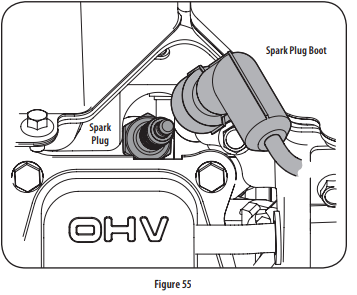
Remove the spark plug boot and use a spark plug wrench to remove the plug. See Figure 55.
Visually inspect the spark plug. Discard the spark plug if there is apparent wear, or if the insulator is cracked or chipped. Clean the spark plug with a wire brush if it is to be reused.
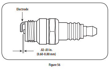
Measure the plug gap with a feeler gauge. Correct as necessary by bending side electrode. See Figure 56. The gap should be set to .02-.03 inches (0.60- 0.80 mm).
Check that the spark plug washer is in good condition and thread the spark plug in by hand to prevent cross-threading.
After the spark plug is seated, tighten with a spark plug wrench to compress the washer.
NOTE: When installing a new spark plug, tighten 1⁄2-turn after the spark plug seats to compress the washer. When reinstalling a used spark plug, tighten 1⁄8- to 1⁄4-turn after the spark plug seats to compress the washer.
CAUTION: The spark plug must be tightened securely. A loose spark plug can become very hot and can damage the engine.
Lubrication
Gear Shaft
The gear (hex) shaft should be lubricated at least once a season or after every 25 hours of operation.
To prevent spillage, remove all fuel from tank by running engine until it stops.
Carefully pivot the snow blower up and forward so that it rests on the auger housing.
Remove the lower frame cover from the underside of the snow blower by removing the self-tapping screws which secure it.
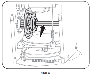
Apply a light coating of anti-seize to the hex shaft. See Figure 57.
NOTE: When lubricating the hex shaft, be careful not to get any oil on the aluminum drive plate or rubber friction wheel. Doing so will hinder the snow blower’s drive system. Wipe off any excess or spilled oil.
Wheels
At least once a season, remove both wheels. Clean and coat the axles with a multipurpose automotive grease before reinstalling wheels.
Chute Directional Control
Once a season, lubricate the eye bolt bushing and spiral with 3-in-1 oil.
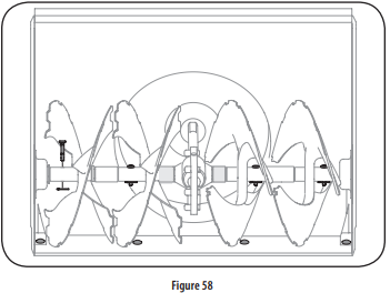
Auger Shaft
At least once a season, remove the shear pins on auger shaft. Spray lubricant inside shaft, and around the spacers and flange bearings found at either end of the shaft. See Figure 58.
Shave Plate and Skid Shoes
The shave plate and skid shoes on the bottom of the snow blower are subject to wear. They should be checked periodically and replaced when necessary.
NOTE: The skid shoes on this machine have two wear edges. When one side wears out, they can be rotated 180° to use the other edge.
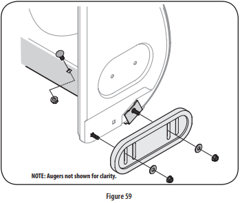
To remove skid shoes:
Remove the two carriage bolts, washers, and hex flange nuts that secure each skid shoe to the snow blower.
Reassemble new skid shoes with the four carriage bolts (two on each side), washers, and hex flange nuts. Refer to Figure 5959.
To remove shave plate:
Remove the carriage bolts and hex nuts which attach it to the snow blower housing.
Reassemble new shave plate, making sure heads of carriage bolts are to the inside of housing. Tighten securely. See Figure 59.
Adjustments
Shift Cable
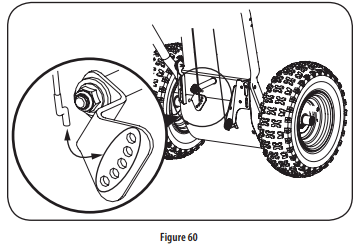
If full range of speeds (forward and reverse) cannot be achieved use the mounting holes in the index bracket to adjust the shift cable tension as follows:
Place shift lever in fastest forward speed position (F6).
Lift the shift cable index bracket (a) up to create slack in the cable (b). See Figure 60.
Disengage the Z fitting (c) from the index bracket.
Select new mounting hole and reinsert Z fitting into the index bracket. Using the upper mounting holes will loosen the shift cable. Using the lower mounting holes will tighten the shift cable.
Reinsert the Z fitting into the index bracket.
To ensure proper shift cable tension perform the following:
Start the engine and place the shift lever in the slowest forward speed. Using the drive control, ensure the unit moves forward.
Place the shift lever in the slowest reverse speed. Using the drive control, ensure the unit moves in reverse.
If necessary continue to adjust cable until the conditions in Steps a and b are satisfied.
Shift Rod
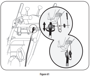
If the full range of speeds (forward and reverse) cannot be achieved, refer to the Figure 61 and adjust the shift cable as follows:
Place the shift lever in the fastest forward speed position (F6).
Remove cotter pin and washer from adjustment ferrule on shift rod and pull it out from shift lever. See Figure 61.
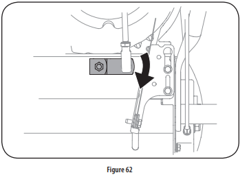
Pivot shift bracket downward as far as it will go. See Figure 62.
Rotate ferrule up or down on shift rod as necessary until it lines up with upper hole in shift lever. Refer to Figure 61 inset.
Insert the ferrule into the upper hole and secure with the washer and cotter pin.
Drive Control
When the drive control is released and in the disengaged “up” position, the cable should have very little slack. It should NOT be tight. Also, if there is excessive slack in the drive cable or if the unit experiences intermittent drive while using, the cable may need to be adjusted. Check the adjustment of the drive control as follows:
With the drive control released, push the snow blower gently forward. The unit should roll freely.
Engage the drive control and gently attempt to push the snow blower forward. The wheels should not turn. The unit should not roll freely.
With the drive control released, move the shift lever back and forth between the R2 position and the F6 position several times. There should be no resistance in the shift lever.
If any of the above tests failed, the drive cable is in need of adjustment. Proceed as follows:
Shut off the engine as instructed in the Operation section.
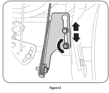
Loosen the lower hex bolt on the drive cable bracket. See Figure 63.
Position the bracket upward to provide more slack (or downward to increase cable tension).
Retighten the lower hex bolt.
Chute Control Rod
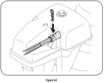
To achieve more chute control rod engagement in the input shaft under the handle panel, the chute control rod will have to be adjusted. Refer to Figure 64.
To adjust this rod, proceed as follows:
Remove the cotter pin from the hole closest to the chute control head on the chute control input.
Pull out the chute control rod until the hole in it lines up with the other hole in the chute control input.
Reinsert the cotter pin through this hole and the chute control rod.
Chute Bracket
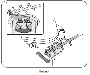
If the spiral at the bottom of the chute directional control is not fully engaging with the chute assembly, the chute bracket can be adjusted. To do so:
Loosen the two nuts which secure the chute bracket and reposition it slightly. See Figure 65.
Retighten the nuts.
Chute
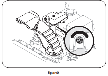
If the chute fails to remain stationary during operation, the pre-load of the chute can be adjusted by tightening the hex nut found on the front of the chute control head.
To increase the preload, tighten the hex nut clockwise in ¼ turn intervals. See Figure 66.
If the chute directional control is difficult to crank, decrease the preload by loosening the hex nut counterclockwise in ¼ turn intervals.
Auger Control
Refer to the Assembly section for instructions on adjusting the auger control cable.
Skid Shoes
Refer to the Assembly section for instructions on adjusting the skid shoes.
Belt Replacement
Auger Belt
To remove and replace your snow blower’s auger belt, proceed as follows:
1. To prevent spillage, remove all fuel from tank by running engine until it stops.
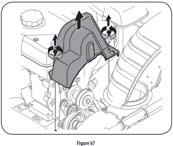
2. Remove the plastic belt cover on the front of the engine by removing the two self-tapping screws. See Figure 67.
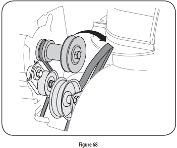
3. Roll the auger belt off the engine pulley. See Figure 68.
4. Carefully pivot the snow blower up and forward so that it rests on the auger housing
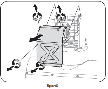
5. Remove the frame cover from the underside of the snow blower by removing four self-tapping screws which secure it. See Figure 69.
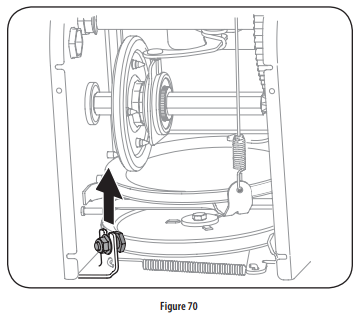
6. Loosen and remove the shoulder screw which acts as a belt keeper. Refer to Figure 70.
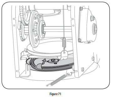
7. Remove the belt from around the auger pulley, and slip the belt between the support bracket and the auger pulley. See Figure 71.
NOTE: Engaging the auger control will ease removal and reinstallation of the belt.
8. Reassemble auger belt by following instructions in reverse order. NOTE: Do NOT forget to reinstall the shoulder screw and reconnect the spring to the frame after installing a replacement auger belt.
9. Perform the Auger Control test outlined in the Assembly section of this manual.
Drive Belt
NOTE: Several components must be removed and special tools are required in order to replace the snow blower’s drive belt. Contact the nearest Sears Parts & Repair Center to have the drive belt replaced.
Friction Wheel Inspection (Steerable 500 and 800 Series & NonSteerable Single Speed 600 Series)
If the snow blower fails to drive with the drive control engaged, and performing the drive control cable adjustment fails to correct the problem, the friction wheel may need to be replaced. Follow the instructions below. Examine the friction wheel rubber for signs of wear or cracking and replace wheel if necessary.
To prevent spillage, remove all fuel from tank by running engine until it stops.
Place the shift lever in first Forward (F1) position.
Carefully pivot the snow blower up and forward so that it rests on the auger housing.
Remove the frame cover from the underside of the snow blower by removing the self-tapping screws which secure it.
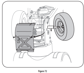
Remove the right-hand wheel by removing the screw and bell washer which secure it to the axle. See Figure 72.
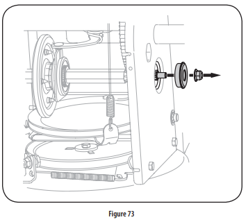
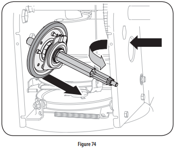
Carefully remove the hex nut and washer which secures the hex shaft to the snow blower frame and lightly tap the shaft’s end to dislodge the ball bearing from the right side of the frame. See Figure 73. NOTE: Be careful not to damage the threads on the shaft.
Carefully position the hex shaft downward and to the left before carefully sliding the friction wheel assembly off the shaft. See Figure 74. NOTE: If you’re replacing the friction wheel assembly as a whole, discard the worn part and slide the new part onto the hex shaft.
Follow the steps above in reverse order to reassemble components.
Perform the test previously described in the Drive Control section.
If you’re disassembling the friction wheel and replacing only the rubber ring, proceed as follows:
NOTE: Not all friction wheels are serviceable. If this is the case, simply replace the friction wheel assembly.
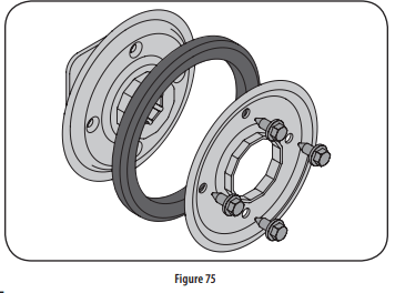
Remove the four screws which secure the friction wheel’s side plates together. See Figure 75.
Remove the rubber ring from between the plates.
Reassemble the side plates with a new rubber ring. NOTE: When reassembling the friction wheel assembly, make sure that the rubber ring is centered and seated properly between the side plates. Tighten each screw only one rotation before turning the wheel clockwise and proceeding with the next screw. Repeat this process several times to ensure the plates are secured with equal force (between 6 ft-lbs and 9 ft-lbs).
Slide the friction wheel assembly back onto the hex shaft and follow the steps above in reverse order to reassemble components.
Perform the test previously described in the Drive Control section.
OFF-SEASON STORAGE
If the snow blower will not be used for 30 days or longer, or if the end of the snow season, the equipment needs to be stored properly. Follow storage instructions below to ensure top performance from the snow blower for future use.
Preparing Engine
Engines stored over 30 days need to be drained of fuel to prevent deterioration and gum from forming in fuel system or on essential carburetor parts. If the gasoline in your engine deteriorates during storage, you may need to have the carburetor, and other fuel system components, serviced or replaced.
Remove all fuel from tank by running engine until it stops. Do not attempt to pour fuel from the engine.
Change the engine oil.
Remove spark plug and pour approximately 1 oz. (30 ml) of clean engine oil into the cylinder. Pull the recoil starter several times to distribute the oil, and reinstall the spark plug.
Clean debris from around engine, and under, around, and behind muffler. Apply a light film of oil on any areas that are susceptible to rust.
Store in a clean, dry and well ventilated area away from any appliance that operates with a flame or pilot light, such as a furnace, water heater, or clothes dryer. Avoid any area with a spark producing electric motor, or where power tools are operated.
WARNING: Never store snow blower with fuel in tank indoors or in poorly ventilated areas, where fuel fumes may reach an open flame, spark or pilot light as on a furnace, water heater, clothes dryer or gas appliance.
If possible, avoid storage areas with high humidity.
Keep the engine level during storage. Tilting can cause fuel or oil leakage.
Preparing Snow Blower
When storing the snow blower in an unventilated or metal storage shed, care should be taken to rustproof the equipment. Using a light oil or silicone, coat the equipment, especially any chains, springs, bearings and cables.
Remove all dirt from exterior of engine and equipment.
Follow lubrication recommendations.
Store equipment in a clean, dry area.
Inflate the tires to the tire manufacturers recommended pressure. Refer to tire sidewall.
Store snow blower in operating position with both wheels and shave plate on level ground surface.
TROUBLESHOOTING
WARNING: Disconnect the spark plug wire and ground it against the engine to prevent unintended starting. Before performing any type of maintenance/service, disengage all controls and stop the engine. Wait until all moving parts have come to a complete stop. Always wear safety glasses during operation or while performing any adjustments or repairs.
This section addresses minor service issues. To locate the nearest Sears Service Center or to schedule service, call the following toll free number: 1-888-331-4569.
Problem
Cause
Remedy
Engine fails to start
Choke control not in CHOKE position.
Spark plug wire disconnected.
Faulty spark plug.
Fuel tank empty or stale fuel.
Engine not primed.
Safety key not inserted.
Extension cord not connected (when using electric start button, on models so equipped).
Move choke control to CHOKE position.
Connect wire to spark plug.
Clean, adjust gap, or replace.
Fill tank with clean, fresh gasoline.
Prime engine as instructed in the Operation section.
Insert safety key fully into the switch.
Connect one end of the extension cord to the electric starter outlet and the other end to a three-prong 120V, grounded, AC outlet.
Engine running erratically/ inconsistent RPM (hunting or surging)
. Engine running on CHOKE.
Stale fuel.
Water or dirt in fuel system.
Carburetor out of adjustment.
Over-governed engine
Move choke control to RUN position.
Fill tank with clean, fresh gasoline.
Drain fuel tank by running engine until it stops. Refill with fresh fuel.
Contact a Sears or other qualified service dealer for repair.
Contact a Sears or other qualified service dealer for repair.
Excessive vibration
Loose parts or damaged auger or impeller.
Stop engine immediately and disconnect spark plug wire. Tighten all bolts and nuts. If vibration continues, have unit serviced by a Sears Parts & Repair Center.
Loss of power
Spark plug wire loose.
Gas cap vent hole plugged
Connect and tighten spark plug wire.
Remove ice and snow from gas cap. Be certain vent hole is clear.
Unit fails to propel itself
Drive cable in need of adjustment.
Drive belt loose or damaged.
Worn friction wheel
Adjust drive control cable. Refer to Service and Maintenance section.
Contact a Sears or other qualified service dealer for repair using identical replacement part.
Have friction wheel replaced by a Sears or other qualified service dealer using identical replacement part.
Unit fails to discharge snow
Chute assembly clogged.
Foreign object lodged in auger.
Auger cable in need of adjustment.
Auger belt loose or damaged.
Shear pin(s) sheared.
Stop engine immediately and disconnect spark plug wire. Clean chute assembly and inside of auger housing with clean-out tool.
Stop engine immediately and disconnect spark plug wire. Remove object from auger with clean-out tool.
Adjust auger control cable. Refer to Assembly section.
Replace auger belt. Refer to Service and Maintenance section.
Replace with new shear pin(s). Refer to Operation section
Chute fails to easily rotate 180-200 degrees
Chute assembled incorrectly.
Disassemble chute control and reassemble as directed in the Assembly section.
Unit plows snow instead of blowing it
Low/slow ground speed in wet/slushy snow 1-3” deep.
Shear pin(s) sheared.
Increase ground speed. Always operate engine at FULL throttle.
Replace with new shear pin(s). Refer to Operation section.
 STOP: Refer to Figure 1 to identify your applicable chute style and continue to Chute Assembly Options (page 9).

 position.
  position (cold engine start). If engine is warm, place choke in RUN position.