
Write the model and serial
numbers here:
Model # _________________
Serial # _________________
Find these numbers on a label
behind the room cover on the
base pan.
GE is a trademark of the General Electric Company. Manufactured under trademark license.
OWNER’S MANUAL
AIR CONDITIONER
Zoneline
®
49-7774 05-17 GEA
SAFETY INFORMATION .........3
USING THE ZONELINE
Controls ..............................6
Air Direction ..........................7
To Remove the Room Cover ............7
Ventilation Control .....................7
Auxiliary Controls ......................8
Remote Thermostat ...................12
Makeup Air ..........................13
CARE AND CLEANING
Base Pan ............................14
Outdoor Coils ........................14
Room Cover and Case .................14
Ventilation Filter ......................15
Air Filters ............................15
INSTALLATION INSTRUCTIONS
Preparation ..........................16
Replacing an Existing Unit .............17
Electrical Connection ..................18
Installing the Zoneline .................21
Optional Drain Kit ....................23
TROUBLESHOOTING TIPS ..... 24
Normal Operating Sounds ............ 26
CONSUMER SUPPORT
Ownership Registration ................27
Warranty ............................31
Consumer Support ....................32
AZ45
AZ65
ESPAÑOL
For a Spanish version of this
manual, visit our Website at
www.zoneline.com.
Para consultar una version
en español de este manual
de instrucciones, visite nuestro
sitio de internet
www.zoneline.com.
FRANÇAIS
For a French version of this
manual, visit our Website at
www.zoneline.com.
Pour un version français de
ce manuel d’utilisation, veuillez
visiter notre site web à l’adresse
www.zoneline.com.

2 49-7774
THANK YOU FOR MAKING GE APPLIANCES A PART OF YOUR HOME.
Whether you grew up with GE Appliances, or this is your first, we’re happy to have you in the family.
We take pride in the craftsmanship, innovation and design that goes into every GE Appliances
product, and we think you will too. Among other things, registration of your appliance ensures that we
can deliver important product information and warranty details when you need them.
Register your GE appliance now online. Helpful websites and phone numbers are available in the
Consumer Support section of this Owner’s Manual. You may also mail in the pre-printed registration
card included in the packing material.
49-7774 3
READ AND SAVE THESE INSTRUCTIONS
IMPORTANT SAFETY INFORMATION
READ ALL INSTRUCTIONS BEFORE USING THE APPLIANCE
SAFETY INFORMATION
For your safety, the information in this manual must be followed to minimize the risk of fire or
explosion, electric shock, or to prevent property damage, personal injury, or loss of life.
SAFETY PRECAUTIONS
WARNING
Ŷ7KLV=RQHOLQHPXVWEHSURSHUO\LQVWDOOHGLQDFFRUGDQFHZLWKWKH,QVWDOODWLRQ,QVWUXFWLRQVEHIRUHLWLV
XVHG6HHWKH,QVWDOODWLRQ,QVWUXFWLRQVLQWKHEDFNRIWKLVPDQXDO
Ŷ,PPHGLDWHO\UHSODFHDOOHOHFWULFVHUYLFHFRUGVWKDWKDYHEHFRPHIUD\HGRURWKHUZLVHGDPDJHG$
damaged power supply cord must be replaced with a new power supply cord obtained from the
manufacturer and not repaired. Do not use a cord that shows cracks or abrasion damage along its
length or at either the plug or connector end.
Ŷ8QSOXJRUGLVFRQQHFWWKH=RQHOLQHDWWKHIXVHER[RUFLUFXLWEUHDNHUEHIRUHPDNLQJDQ\UHSDLUV
NOTE: We strongly recommend that any servicing be performed by a qualified individual.
Ŷ7KHVH5$DLUFRQGLWLRQLQJV\VWHPVUHTXLUHFRQWUDFWRUVDQGWHFKQLFLDQVWRXVHWRROVHTXLSPHQW
and safety standards approved for use with this refrigerant. DO NOT use equipment certified for
R22 refrigerant only.
Replacing an existing unit?
)RUGHWDLOVVHHWKH,QVWDOODWLRQ,QVWUXFWLRQVLQWKLVPDQXDO
49-7774
SAFETY INFORMATION
LIRE ET CONSERVER CES INSTRUCTIONS
CONSIGNES DE SÉCURITÉ IMPORTANTES
LISEZ TOUTES LES INSTRUCTIONS AVANT L’UTILISATION
Pour votre sécurité, veuillez observer les consignes de ce manuel afin de réduire le risque d’incendie,
d’explosion, de choc électrique, de dommages à la propriété ou de blessures, graves ou fatales.
MESURES DE SÉCURITÉ
Ŷ$YDQWVRQXWLOLVDWLRQFHFOLPDWLVHXU=RQHOLQHGRLWrWUHLQVWDOOpFRUUHFWHPHQWHQFRQIRUPLWpDYHFOHV
instructions d’installation. Consultez les instructions d’installation au dos de ce manuel.
Ŷ5HPSODFH]LPPpGLDWHPHQWWRXVOHVFRUGRQVpOHFWULTXHVXVpVRXDXWUHPHQWHQGRPPDJpV8QFRUGRQ
pOHFWULTXHHQGRPPDJpQHGRLWSDVrWUHUpSDUpLOGRLWrWUHUHPSODFpSDUXQFRUGRQQHXIDFTXLVDXSUqV
GXIDEULFDQW1¶XWLOLVH]SDVXQFRUGRQTXLSUpVHQWHGHVILVVXUHVRXGHVPDUTXHVG¶DEUDVLRQVXUVD
ORQJXHXUVDILFKHRXVDFRQQH[LRQ
Ŷ'pEUDQFKH]OHFOLPDWLVHXU=RQHOLQHRXFRXSH]OHFRXUDQWjODERvWHGHIXVLEOHVRXDXGLVMRQFWHXU
DYDQWG¶HIIHFWXHUXQHUpSDUDWLRQ
REMARQUE: 1RXVUHFRPPDQGRQVYLYHPHQWTXHOHVUpSDUDWLRQVVRLHQWHIIHFWXpHVSDUXQHSHUVRQQH
TXDOLILpHHQODPDWLqUH
Ŷ/HVRXWLOVOHVpTXLSHPHQWVHWOHVQRUPHVGHVpFXULWpXWLOLVpVSDUOHVHQWUHSUHQHXUVHWOHVWHFKQLFLHQV
GRLYHQWrWUHDSSURXYpVHQIRQFWLRQGXIOXLGHIULJRULJqQHGRQWOHV\VWqPHGHFOLPDWLVDWLRQ5$GX
=RQHOLQHHVWpTXLSpN’UTILISEZ PAS d’équipements certifiés relativement au fluide frigorigène
R22 seulement.
Vous remplacez un climatiseur existant?
Pour de plus amples renseignements, veuillez consulter les instructions d’installation de ce manuel.
AVERTISSEMENT

49-7774 5
SAFETY INFORMATION
LEA Y GUARDE ESTAS INSTRUCCIONES
INFORMACIÓN IMPORTANTE DE SEGURIDAD
LEA TODAS LAS INSTRUCCIONES ANTES DE USAR
Para su seguridad, se debe seguir la información de este manual para minimizar el riesgo de incendio o
explosión, descargas eléctricas, o para evitar daños a la propiedad, lesiones personales o la muerte.
PRECAUCIONES DE SEGURIDAD
Ŷ$QWHVGHLQLFLDUVXXVRHODFRQGLFLRQDGRUGHDLUH=RQHOLQHGHEHLQVWDODUVHFRUUHFWDPHQWHVHJ~QODV
,QVWUXFFLRQHVGHLQVWDODFLyQ9HUODV,QVWUXFFLRQHVGHLQVWDODFLyQHQODSDUWHWUDVHUDGHHVWHPDQXDO
Ŷ5HHPSODFHLQPHGLDWDPHQWHWRGRVORVFDEOHVHOpFWULFRVTXHVHKD\DSHODGRRTXHVHKD\DQGDxDGR
GHDOJXQDRWUDPDQHUD8QFDEOHGHFRUULHQWHGDxDGRQRGHEHUHSDUDUVHVLQRTXHGHEHVHU
VXVWLWXLGRSRUXQRQXHYRTXHVHDGTXLHUDGHOIDEULFDQWH1RXVHXQFDEOHHOpFWULFRTXHPXHVWUH
HYLGHQFLDVGHGHWHULRURRGDxRVGHDEUDVLyQHQVXVXSHUILFLHRHQFXDOTXLHUDGHVXVHQFKXIHVR
H[WUHPRV
Ŷ'HVHQFKXIHRGHVFRQHFWHHO=RQHOLQHGHVGHODFDMDGHIXVLEOHVRHOGLV\XQWRUDQWHVGHUHDOL]DU
FXDOTXLHUWLSRGHUHSDUDFLyQ
NOTA: 5HFRPHQGDPRVHQpUJLFDPHQWHTXHFXDOTXLHUVHUYLFLROOHYDGRDFDERHQHVWHHTXLSRORUHDOLFH
un individuo calificado.
Ŷ/RVVLVWHPDVGHDFRQGLFLRQDGRUGHDLUH5$UHTXLHUHQTXHORVFRQWUDWLVWDV\WpFQLFRVXWLOLFHQ
herramientas, equipamiento y normas de seguridad aprobadas para su uso con este refrigerante.
NO utilice equipamiento certificado sólo para refrigerante R22.
¿Desea reemplazar una unidad ya instalada?
3DUDPiVGHWDOOHVYHUODV,QVWUXFFLRQHVGHLQVWDODFLyQHQHVWHPDQXDO
ADVERTENCIA

6 49-7774
USING THE ZONELINE
Controls
About Your Heat Pump (AZ65 only)
Heat pumps can save money by removing heat from the
outside air—even when the outside temperature is below
freezing—and releasing that heat indoors.
7RJHWWKHEHVWHQHUJ\SHUIRUPDQFHIURP\RXUKHDWSXPS
don’t change the room thermostat by more than one degree
at one time. Raising the heat setting 2–3 degrees will cause
WKH=RQHOLQHWRXVHLWVHOHFWULFKHDWLQJHOHPHQWVLQRUGHUWR
reach the new temperature setting quickly.
7KHHOHFWULFKHDWLQJHOHPHQWVXVHPRUHHOHFWULFLW\WKDQKHDW
pumps and cost more to operate.
7KHUHLVDPLQXWHPLQLPXPFRPSUHVVRUUXQWLPHDWDQ\
setting to prevent short cycling.
7KHIDQVVWDUWEHIRUHWKHFRPSUHVVRUDQGVWRSDIWHUWKH
compressor cycles off.
When the outdoor temperature is lower than 25°F, heat is
provided by the electric heater instead of by the heat pump.
Temp Control
7KHWHPSFRQWUROLVXVHGWRPDLQWDLQWKHURRPWHPSHUDWXUH
7KHV\VWHPZLOOF\FOHRQDQGRIIWRNHHSWKHURRPDWWKH
same level of comfort.
Press the + pad to raise the temperature.
Press the - pad to lower the temperature.
NOTE: 7KHGLVSOD\VKRZVWKHVHWWHPSHUDWXUHQRWWKH
room temperature.
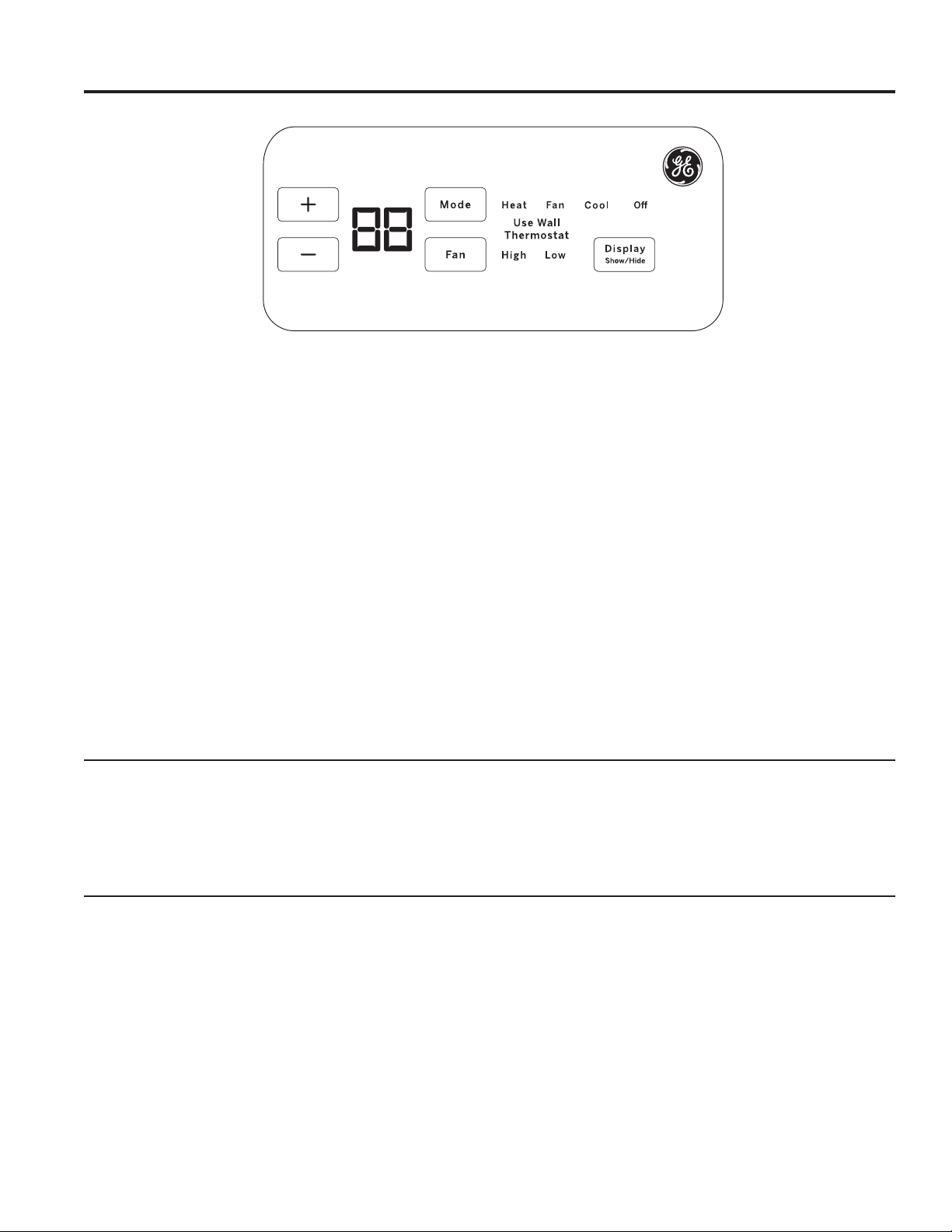
Fan, Mode and Operation Control
FAN—Sets the fan operation for HIGH or LOW.
MODE— COOL—For cooling
FAN—For fan-only operation
HEAT—For heating
OFF—7XUQVWKHXQLWRII3RZHUUHPDLQV
FRQQHFWHGWRWKH=RQHOLQH7KH)UHH]H+HDW
Sentinel features still function if active. See the
Freeze/Heat Sentinel section on page 8.
USE WALL THERMOSTAT—7KLV/('ZLOOOLJKWXSZKHQ
the unit is controlled by a wall thermostat. See page 9 for
details.
Control Lock Out
7KHFRQWUROSDQHOFDQEHORFNHGRXWWRSUHYHQWXVHUVIURP
changing the operation mode of the unit.
While the unit is in the desired operating mode, press and
KROGWKH',63/$<6+2:+,'(EXWWRQIRUVHFRQGVWR
lock the control and the desired setting. Any key press after
WKDWZLOOUHVXOWLQWKHPRGH/('DQGWHPSHUDWXUHWKDWZDV
locked to flash 5 times and then go dormant.
7RXQORFNWKHFRQWUROORFNRXWIHDWXUHSUHVVWKH',63/$<
6+2:+,'(EXWWRQIRUVHFRQGVWRXQORFNDQGUHVXPH
normal operation.
NOTE: The temperature display will flash if the control
panel is locked (see Control Lock Out section).
NOTE: When switching between modes, it may take
several minutes to completely change operation.
Quick Heat Recovery
Activates each time the thermostat is switched from OFF or
COOL mode to HEAT mode. Electric heaters are energized
until the thermostat set point is reached. On heat pump
PRGHOVWKHKHDWSXPSRSHUDWLRQZLOOUHVXPHDWWKHQH[W
call for heat.
49-7774 7
Using the Zoneline
USING THE ZONELINE
Ventilation Control*
NOTE: Two shipping screws must be removed from the
vent door before use. See the Installation Instructions in the
back of this manual. If you do not plan to use the ventilation
feature, leave the two screws in place.
7KHYHQWLODWLRQFRQWUROOHYHULVORFDWHGDWWKHORZHUOHIWVLGH
RIWKH=RQHOLQHXQLWEHKLQGWKHURRPFRYHU7KHSRVLWLRQ
RIWKHOHYHUFDQEHDGMXVWHGZLWKWKHZLQJQXW
When set at the closed position, only the air inside the
room is circulated and filtered.
When set in an open position, some outdoor air will be
GUDZQLQWRWKHURRP7KLVZLOOUHGXFHWKHKHDWLQJRUFRROLQJ
efficiency.
Energy Tip: Keep the vent control in the closed position to
prevent unconditioned air from entering the room.
* Not on Make Up Air Module
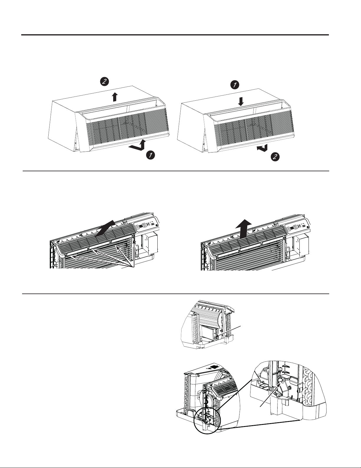
Air Direction
7RFKDQJHWKHDLUGLUHFWLRQUHPRYHWKHURRPFRYHU
5HPRYHWKHORXYHUVFUHZVWKDWKROGWKHORXYHULQVHUW
LQSODFH5RWDWHWKHORXYHUUHLQVWDOODQGUHSODFHWKH
screws and the room cover.
To Remove the Room Front
Additional controls are located behind the room cover.
To remove: Pull out at the bottom to release it from the
KROGLQJWDEVRQWKHVLGHV7KHQOLIWXS
To replace: Align and place the top rail of the room cover
RYHUWKHFKDVVLV3XVKLQZDUGDWWKHERWWRPXQWLOLW
VQDSVLQWRSODFH
Remove the
shipping screws
(if operation is
GHVLUHG
/RXYHUVFUHZV
)DFWRU\6KLSSHG/RXYHU2ULHQWDWLRQ
DLUIORZ#IURPKRUL]RQWDO
0RGLILHG/RXYHU2ULHQWDWLRQ
DLUIORZ#IURPKRUL]RQWDO
9HQW&RQWURO
8 49-7774
Auxiliary controls on your Zoneline
USING THE ZONELINE
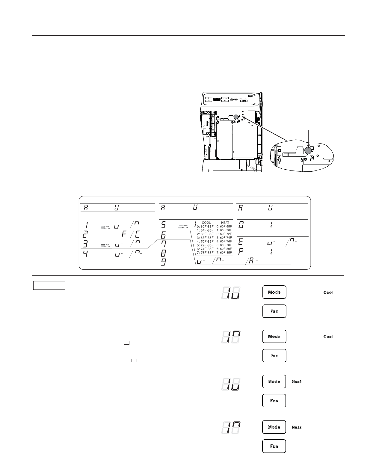
Auxiliary Controls - Aux Set Button
While the unit is preset to what most customers prefer, the
DX[LOLDU\FRQWUROVORFDWHGEHKLQGWKHURRPFRYHUEHORZWKH
control panel.
5HPRYHWKHURRPFRYHU6HHWKH7R5HPRYHWKH5RRP
Cover section.
,IWKHRZQHUPRGLILHVWKHDX[LOLDU\FRQWUROVLWLVWKHQWKH
RZQHULVUHVSRQVLEOHIRUHQVXULQJWKHDX[LOLDU\FRQWUROVDUH
VHWWRWKHGHVLUHGIXQFWLRQ7KHUHDUHGLIIHUHQWPRGHV
WKDWFDQEHVHWXVLQJWKHDX[LOLDU\VHWEXWWRQ
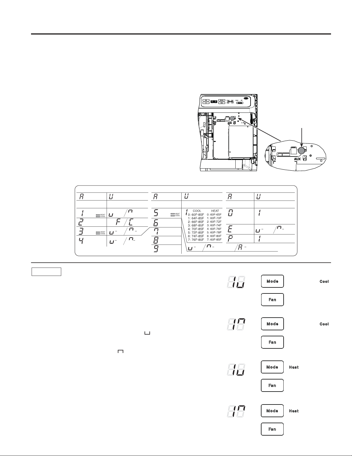
7RFKDQJHRSHUDWLQJRUVHWXSSDUDPHWHUVILUVWJRWRWKH
mode control and turn the unit off, then, press the red
AUX SETEXWWRQ³$8´DSSHDUVRQWKHGLVSOD\
Press the mode button on the control pad until the first digit
in the display shows the number corresponding to the mode
\RXDUHFKRRVLQJDQGWKHFRUUHFW+($7&22//('LVOLW
Press the +/- button to make the mode setting selection
ZKHUHDSSOLFDEOHVKRZQLQWKHVHFRQGGLJLWRIWKHGLVSOD\
Press the red AUX SET button to lock in the selection, and
H[LW$8;6(7PRGH
Red
$X[6HW
Button
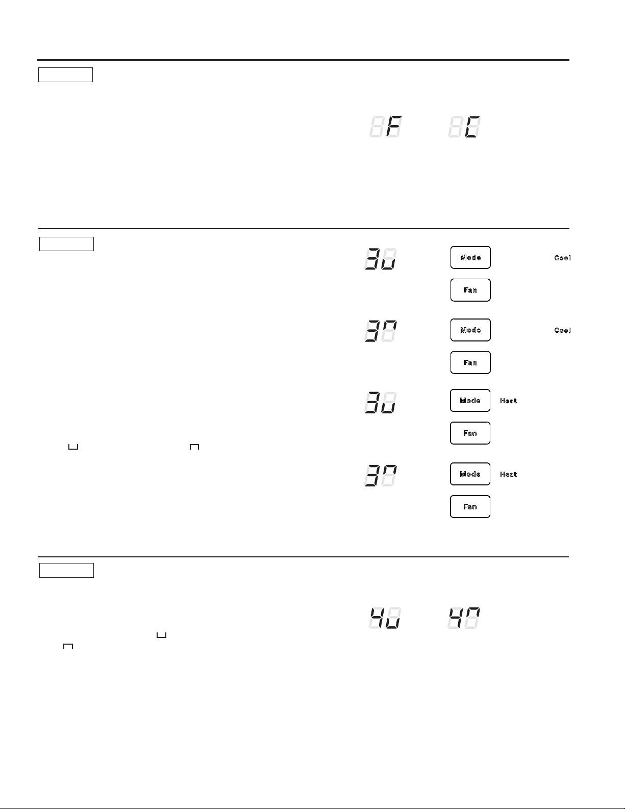
MODE 1
Smart Fan—Cooling/Heating
Press MODE XQWLODDSSHDUVLQWKHILUVWGLJLWRIWKHGLVSOD\
for Smart FanFRROPRGH7KHCOOL/('OLJKWRQWKH
PDLQFRQWUROZLOOEHRQ7RFKDQJHWRKHDWPRGHSUHVV
MODE DJDLQ7KHHEAT/('OLJKWRQWKHPDLQFRQWUROZLOO
be lit.
3UHVVWKHSDGWRVHWWKHLQGRRUIDQWRF\FOHRQRIILQWKH
heating or cooling mode selected “ ´
Press the + pad to set the indoor fan to run continuously in
the heating or cooling mode selected “ ´
Press AUX SETWRFRQILUP\RXUVHOHFWLRQDQGH[LWAUX
SET mode, or press MODE to continue setting other
functions.
7KHGHIDXOWVHWWLQJIRU0RGHLVDVIROORZV
&RROLQJ&RQWLQXRXV21
+HDWLQJ&\FOH2))
*Note:,QF\FOLFFRROLQJPRGHWKHLQGRRUIDQZLOODFWLYDWH
RFFDVLRQDOO\WRYHULI\DLUWHPSHUDWXUHLQWKHURRP,QF\FOLF
heating mode, the fan will continue to operate for several
seconds after the heating function has stopped in order to
increase unit efficiency.
(AZ65 Only)
(AZ65 Only)
Temperature
Limit
Class 2
Mode
Duct Mode *
All I2R Mode
Boost Heat
Press “Aux Set”
First Digit Second Digit
Press “Mode” Press +
/
-
Makeup Air
Mode *
Makeup Air
Occupancy *
Press “Aux Set”
First Digit Second Digit
Press “Mode” Press
0: OFF
1: 25CFM
2: 30CFM
3: 35CFM
Disable
293D2203P003
Enable
+
/
-
Off On
Press “Aux Set”
First Digit
Press “Mode”
Second Digit
Press
- Cycle - Continue
+
/
-
Smart Fan
Temperature
Display
Sentinel
Constant
Fan
Off On
4: 40CFM
5: 45CFM
6: 50CFM
Off On (Cool/Heat) On (Auto Change Over)
Engineering
Revision*
Press +/- to match last
digit of model number
* Not available on all models.
49-7774 9
Auxiliary controls on your Zoneline
USING THE ZONELINE
MODE 2
Fahrenheit / Celsius
7KLVIHDWXUHDOORZVWKHLQGLYLGXDOWRVZLWFKWKH
temperature units between Fahrenheit and Celsius on
the display.
Press MODE until a 2 appears in the first digit of the
GLVSOD\IRU)DKUHQKHLW&HOVLXVPRGH
Press the - pad to select Celsius or the + pad to select
)DKUHQKHLW7KHLQGLYLGXDOZLOOVHHDQ)IRU)DKUHQKHLWRU
a C for Celsius in the second digit of the display based
on the selection.
7KHGHIDXOWVHWWLQJIRU0RGHLV)DKUHQKHLW
° F
° C
MODE 3
Freeze Sentinel/Heat Sentinel
With power to the unit and Freeze Sentinel activated,
the unit automatically provides heat without user
LQWHUIDFH7KLVSUHYHQWVSRWHQWLDOSOXPELQJGDPDJHE\
WXUQLQJWKHKHDWHUDQGLQGRRUIDQ21DW)DQGWKHQ
2))RQFHWKHURRPWHPSHUDWXUHUHDFKHV)
When Heat Sentinel is activated, the unit automatically
SURYLGHVFRROLQJZLWKRXWXVHULQWHUIDFH7KLVSUHYHQWVDQ
H[FHVVLYHO\KRWURRPE\WXUQLQJWKHDLUFRQGLWLRQHU21DW
)DQGWKHQ2))RQFHWKHURRPWHPSHUDWXUHUHDFKHV
)
Press MODE until a 3 appears in the first digit of the
display for Freeze Sentinel PRGH7KHCOOL/('OLJKW
on the main control will be on. Press MODE again to
change to the Heat Sentinel7KHHEAT/('OLJKWRQ
the main control will be on. Press the - pad for
OFF “ “ or the + pad for ON “ ³7KLVLVVKRZQLQ
WKHVHFRQGGLJLWRIWKHGLVSOD\3UHVV$8;6(7WRORFN
LQ\RXUVHOHFWLRQDQGH[LW$8;6(7PRGHRUSUHVV
MODE to continue setting other functions.
,QWKHGHIDXOWVHWWLQJIRU0RGHHeat Sentinel is off,
Freeze Sentinel is on.
NOTE: 7KHVHIXQFWLRQVDUHDFWLYHZKHQHYHUWKHXQLWLV
plugged in, even if the unit is turned off.
MODE 4
Constant ON Fan
Press MODE XQWLODDSSHDUVLQWKHILUVWGLJLWRIWKH
display to set the fan to run continuously at high
speed - even if the unit is turned off.
Press the - pad for OFF “ “ or the + pad for
ON “ ´7KLVLVVKRZQLQWKHVHFRQGGLJLWRIWKH
display.
Press AUX SETWRORFNLQ\RXUVHOHFWLRQDQGH[LW
AUX SET mode, or press MODE to continue setting
other functions.
7KHGHIDXOWVHWWLQJIRU0RGHLV2))
Freeze Sentinel OFF
Freeze Sentinel ON
Heat Sentinel OFF
Heat Sentinel ON
Constant
Fan OFF
Constant
Fan ON
49-7774
Auxiliary controls on your Zoneline
USING THE ZONELINE
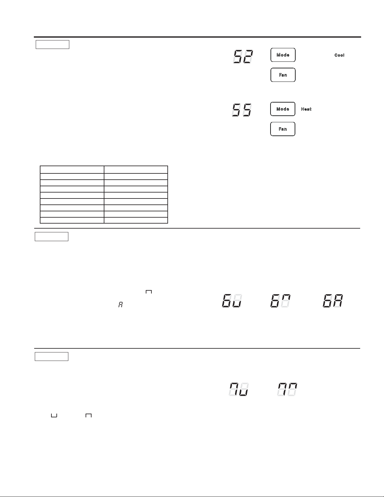
MODE 5
Temperature Limiting
7HPSHUDWXUHOLPLWLQJLVDIHDWXUHWKDWUHGXFHVHQHUJ\
costs by limiting the lowest temperature that can be
obtained in cooling and the highest temperature that can
be obtained in heating.
Press MODE until a 5 appears in the first digit of the
display for Temperature LimitingFRROPRGH7KH
COOL/('OLJKWRQWKHPDLQFRQWUROZLOOEHOLW7R
change to heat mode, press MODE again and the HEAT
/('OLJKWRQWKHPDLQFRQWUROZLOOEHOLW
7RVHWWKHWHPSHUDWXUHOLPLWVSUHVVWKHRUSDG
7KHVHFRQGGLJLWRIWKHGLVSOD\ZLOOEHEHWZHHQDQG
GHSHQGLQJRQWKHOLPLW\RXZDQWWRVHW7KHFKDUWVKRZV
the limits available. Press AUX SET to lock in your
VHOHFWLRQDQGH[LWAUX SET mode, or press MODE to
continue setting other functions.
MODE 6
Use Wall Thermostat
Setting this mode to ON will allow the unit to operate
ZLWKD&ODVV5HPRWH&RQWURO:DOO7KHUPRVWDW
Press MODE until a 6 appears in the first digit of the
display for Class 2 mode.
7KHGHIDXOWVHWWLQJIRU0RGHLV2))
Press the + pad to turn the option ON “ ´IRU
³VWDQGDUGFRROKHDW´WKHUPRVWDWV3UHVVWKH+ pad
again to turn the option ON “ “ for “auto change
RYHU´WKHUPRVWDW<RXPD\SUHVVWKHSDGWRUHWXUQ
to the previous setting. Press AUX SET to lock in your
VHOHFWLRQDQGH[LWAUX SET mode, or press MODE to
continue setting other functions.
:KHQWKLVPRGHLVDFWLYHWKHGLVSOD\ZLOOVKRZ³8VH
:DOO7KHUPRVWDW´ZKHQDQ\NH\LVSUHVVHG
MODE 7
Duct Mode
7KLVVHWWLQJLVXVHGZKHQWKHXQLWLVLQVWDOOHGZLWKDGXFW
DGDSWHUNLW,IWKHXQLWLVGXFWHGWKH'XFW0RGHQHHGV
WREHVHWWR217KLVLQFUHDVHVWKHIDQVSHHGWRHQVXUH
proper circulation.
Press MODE until a 7 appears in the first digit of the
display. Press the + or - pad to set this switch to
OFF “ “ or ON “ ´7KLVLVVKRZQLQWKHVHFRQGGLJLW
of the display. Press AUX SET to lock in your selection
DQGH[LWAUX SET mode.
)RU0RGHO$=SUHVVMODE to continue setting other
functions. Pressing MODE RQ0RGHO$=ZLOOUHWXUQ
you to AUX SETPRGHDQGDQ³$8´ZLOODSSHDULQWKH
display.
7KHGHIDXOWVHWWLQJIRU0RGHLV2))
7HPSHUDWXUHOLPLWV²&RRO 7HPSHUDWXUHOLPLWV²+HDW
)WR) )WR)
)WR) )WR)
)WR) )WR)
)WR) )WR)
)WR) )WR)
)WR) )WR)
)WR) )WR)
)WR) )WR)
7KHGHIDXOWVHWWLQJIRU0RGHLVDV
IROORZV
&RRO)WR)
+HDW)WR)
Temperature Limiting Cool – Limit 2
Temperature Limiting Heat – Limit 5
Duct Mode OFF
Duct Mode ON
Class 2 OFF
Class 2 ON
(Cool/Heat)
Class ON
(Auto Change Over)
49-7774
Auxiliary controls on your Zoneline
USING THE ZONELINE
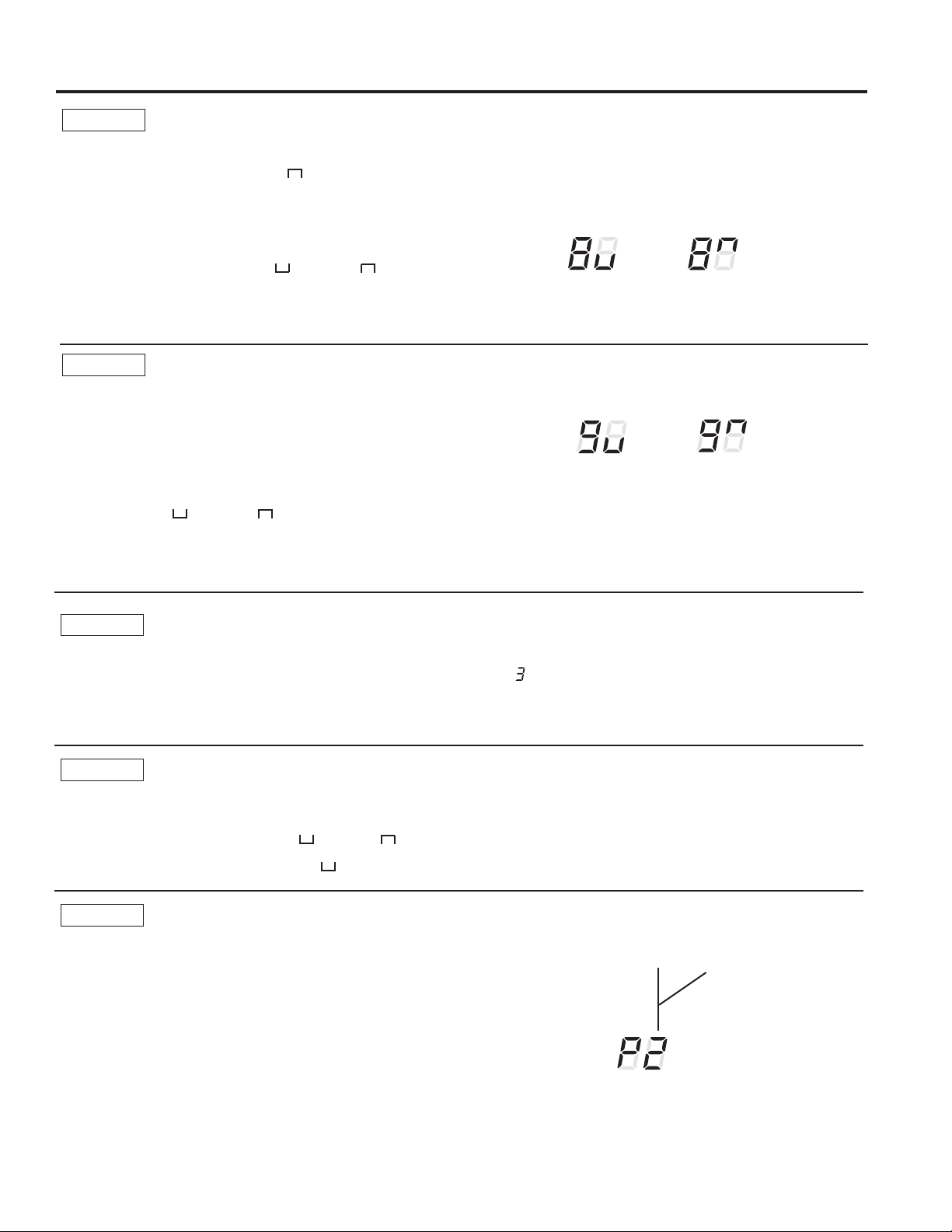
MODE 8
All-Electric Heat (AZ65 only)
7KLVHOHFWULFKHDWRSWLRQIXQFWLRQVRQO\RQWKH$=
model. When this option is ON “
´KHDWSXPS
operation is locked out, causing the unit to provide only
electric resistance heat.
7RVHWAll-Electric Heat option, press MODE until an 8
appears in the first digit of the display. Press the + or -
pad to set this switch to OFF “
“ or ON “ ´7KLVLV
shown in the second digit of the display.
Press AUX SETWRORFNLQ\RXUVHOHFWLRQDQGH[LWAUX
SET mode, or press MODE to continue setting other
functions.
7KHGHIDXOWVHWWLQJIRU0RGHLV2))
MODE 9
Heat Boost (AZ65 only)
When Heat Boost is ON and outside temperatures are
EHWZHHQ)DQG)VXSSOHPHQWDU\HOHFWULFKHDWWR
the heat pump operation to help maintain a consistent,
comfortable room temperature.
7RVHW+HDW%RRVWSUHVVMODE until a 9 appears in the
first digit of the display. Press the + or - pad to set this
switch to OFF “ “ or ON “ ´7KLVLVVKRZQLQWKH
second digit of the display. Press AUX SET to lock in
\RXUVHOHFWLRQDQGH[LWAUX SET mode.
7KHGHIDXOWVHWWLQJIRU0RGHLV2))
All-Electric
Heat OFF
All-Electric
Heat ON
Heat Boost OFF
Heat Boost ON
MODE 0
Digital Makeup Air Module Fan Speed
Press MODE XQWLODDSSHDUVLQWKHILUVWGLJLWRIWKHGLVSOD\
IRUWKH'LJLWDO0DNHXS$LUPRGH7RWXUQRIIWKHPRGXOHRU
FKDQJHWKHIDQVSHHGVSUHVVWKHRUSDGLQGLFDWHV
WKHPRGXOHLVRII PRGXOHRQZLWKIDQVVHWDWFIP
PRGXOHRQZLWKIDQVVHWDWFIPHWF
7KHGHIDXOWVHWWLQJIRU0RGHLV21ZLWKDIDQVSHHGRI
cfm “ “
MODE E
Digital Makeup Air Module Occupancy
7RHQDEOHRFFXSDQF\GHWHFWLRQSUHVV02'(XQWLODQ(
appears in the first digit of the display. Press the + or - pad
to set occupancy detection to OFF “
´RU21³ ´
7KHGHIDXOWVHWWLQJIRU0RGH(LV2))³
´
MODE P
Engineering Revision Setup
7KLVVHWWLQJLVXVHGWRFRQILJXUHWKHXQLWZKHQWKHFLUFXLW
board is replaced.
7KHILUVWWLPHWKHXQLWLVSRZHUHGDIWHUDVHUYLFHERDUGLV
LQVWDOOHGWKHXQLWZLOODXWRPDWLFDOO\HQWHUWKLVPRGH7KH8,
ZLOOUHDG³3´3UHVVWKH³´SDGXQWLOWKHQXPEHUPDWFKHV
WKHHQJLQHHULQJUHYLVLRQDVVKRZQ7KHHQJLQHHULQJUHYLVLRQ
LVWKHODVWQXPEHULQWKHPRGHOQXPEHU3UHVV³$X[´WR
VDYHDQGH[LW
7KHHQJLQHHULQJUHYLVLRQPD\EHDGMXVWHGDIWHUWKHILUVW
SRZHUF\FOHXVLQJ$8;6(73UHVV02'(XQWLO³3´
appears in the first digit, and follow the steps described
above.
Nomenclature Example
AZ45E09DABW2
Engineering Revision
49-7774
Auxiliary controls on your Zoneline
USING THE ZONELINE
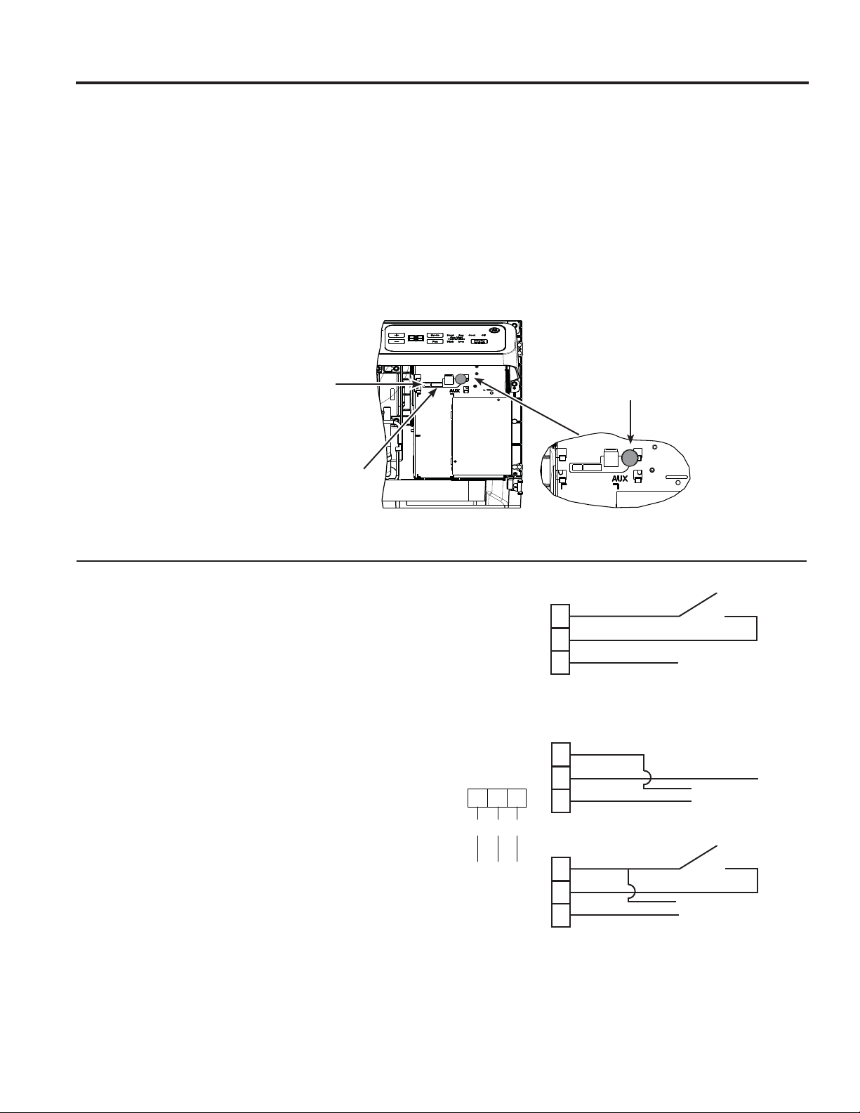
Auxiliary Controls - Terminal Connections
7KHDX[LOLDU\FRQWUROWHUPLQDOFRQQHFWVDUHORFDWHG
behind the room cover beneath the access cover.
7XUQRIIDQGXQSOXJWKHXQLW
5HPRYHWKHURRPFRYHU6HHWKH7R5HPRYHWKH
Room Cover section.
7RPDNHZLULQJFRQQHFWLRQVLQVHUWWKHFRQQHFWRUV
LQWRWKHDSSURSULDWHWHUPLQDOVRQWKHFRQWUROER[
$IWHUDOOGHVLUHGFRQQHFWLRQVKDYHEHHQPDGH
replace the access cover and room cover.
7KHRZQHULVUHVSRQVLEOHIRUPDNLQJDOOFRQQHFWLRQVDQG
setting the appropriate AUX SET mode.
NOTICE:
,PSURSHUZLULQJPD\GDPDJHWKH=RQHOLQHHOHFWURQLFV
No common busing is permitted. Damage or erratic
operation may result. A separate wire pair must be run
from each separate controlling switch to each individual
=RQHOLQH
Red
Aux Set
Button
:KHQFRQQHFWHGDQDX[LOLDU\RUH[WHUQDOIDQFDQEH
FRQWUROOHGZLWKWKHLQGRRUIDQPRWRURQWKH=RQHOLQH
&RQQHFWLRQVSURYLGH9$&WRHQHUJL]HDUHPRWH
relay.
7KH5$.&'&DFFHVVRU\PXVWEHXVHGZKHQXVLQJDQ
H[WHUQDOIDQ
External Fan (Field Installed)
7KH&HQWUDO'HVN&RQWUROLVDIHDWXUHWKDWDOORZVWKHXQLW
WREHPDGHRSHUDEOHLQRSHUDEOHIURPDUHPRWHORFDWLRQ
Operation of the feature requires that an ON-OFF switch
at the remote location be wired to the two CDC terminals
RQWKHFRQWUROSDQHORIWKH=RQHOLQH:KHQWKHUHPRWH
VZLWFKLV&/26('WKHXQLWFDQQRWEHRSHUDWHGLQWKH
)DQ&RRORU+HDWPRGHVE\WKHFRQWURO7KH)UHH]H
Sentinel and the Heat Sentinel features remain operable.
When the remote switch is Open, the unit is fully
operable by control.
7KH5$.&'&DFFHVVRU\PXVWEHXVHGZLWKDFHQWUDO
GHVNFRQWUROV\VWHP1R³&RPPRQ%XVLQJ´LVSHUPLWWHG
,WVKRXOGEHQRWHGWKDW&'&FDQQRWEHXVHGRQ'%0DQG
EBM models when occupancy is enabled.
Central Desk Control (Field Supplied)*
CDC Switch
CDC
CDC
R
R
E. Fan
E. Fan
Connect to external
fan relay
Connect to external
fan relay
CDC Switch
CDC
R
E. Fan
12
3
R
CDC
Ext Fan
RedCDC
Ext Fan
([WHUQDO)DQ&'&
Connector Socket
5HPRWH7KHUPRVWDW
Connector Socket
49-7774
Auxiliary controls on your Zoneline
USING THE ZONELINE
7KH5HPRWH7KHUPRVWDW&RQQHFWRUVDUHLQFOXGHGZLWK
HDFK=RQHOLQH
When connected to a remote thermostat, the indoor
air temperature sensing is shifted from the unit to
the remote thermostat. For this reason, the units will
operate slightly differently when connected to a remote
WKHUPRVWDW7KHIROORZLQJFKDUWVKRZVWKHXQLWRSHUDWLRQ
when connected to a remote thermostat.
IMPORTANT: 7KH=RQHOLQHWKHUPRVWDWFRQQHFWLRQV
SURYLGH9$&RQO\
,IXVLQJDGLJLWDOHOHFWURQLFZDOOWKHUPRVWDW\RXPXVWVHW
LWWRWKH9$&VHWWLQJ6HHWKH,QVWDOODWLRQ,QVWUXFWLRQV
for the wall thermostat.
NOTICE:
'DPDJHWRDZDOOWKHUPRVWDWRUWRWKH=RQHOLQH
electronics can result from improper connections.
Special care must be used in connecting the wires. No
line voltage connections should be made to any circuit.
,VRODWHDOOZLUHVLQEXLOGLQJIURPOLQHYROWDJH
Remote Thermostat
Feature Heat Pump Electric Heat
,QGRRU)URVW&RQWURO Yes Yes
Freeze Sentinel Yes Yes
(OHFWURQLF7HPSHUDWXUH/LPLWLQJ No No
Switch to Resistance Heat Based
RQ,QGRRU7HPSHUDWXUH
'HWHUPLQHGE\5HPRWH7KHUPRVWDW 1$
Switch to Resistance Heat Based
RQ2XWGRRU7HPSHUDWXUH
Yes 1$
Reverse Cycle Defrost Yes 1$
Simultaneous Partial Resistance Heat with
Heat Pump
Yes 1$
5HVLVWDQFH+HDW/RFNRXW Yes 1$
³6PDUW)DQ´)DQ&\FOH )DQ21$8726HW2Q5HPRWH7KHUPR-
stat
)DQ2Q$XWR6HW2Q
5HPRWH7KHUPRVWDW
Central Desk Control Yes Yes
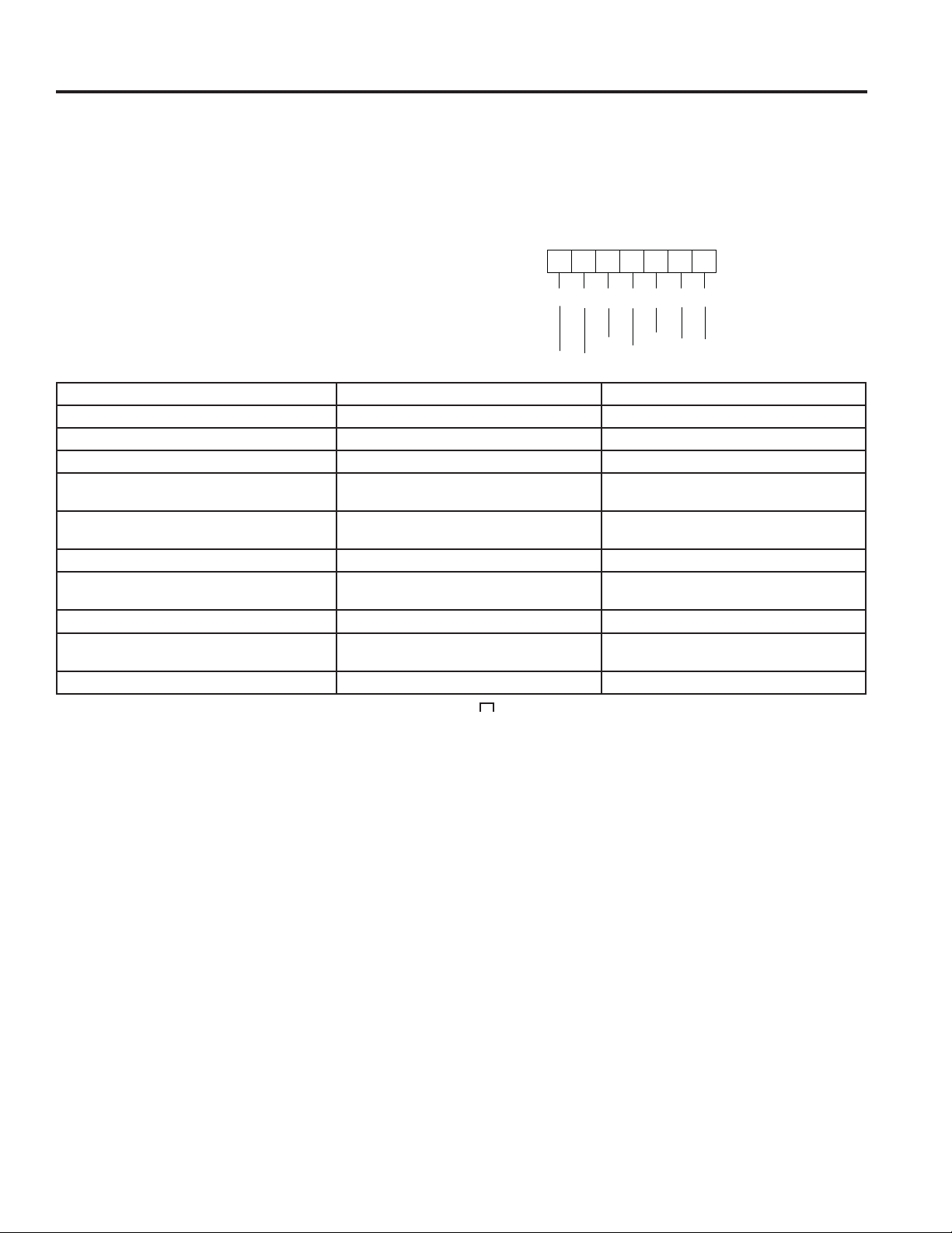
NOTE: 7KH&ODVV0RGHVHWWLQJ0RGHPXVWEHVHWWR21³ “ for the unit to operate with a Class 2 Remote Wall
7KHUPRVWDW6HHWKHLQVWDOODWLRQLQVWUXFWLRQVVXSSOLHGZLWKWKHUHPRWHWKHUPRVWDWDQGPRGHLQVWUXFWLRQVRQSDJH
123456
7
C
W
YB
GH
GL
R
yellow
black
white
blue
green
tan
red

49-7774
USING THE ZONELINE
Makeup Air Models (not on all units)
7KHPDNHXSDLUYHQWLODWLRQV\VWHPLVGHVLJQHGWR
provide continuous outdoor air through the vent door
DQGLQWRWKHURRP,QDGGLWLRQWRSURYLGLQJIUHVKDLULW
dehumidifies incoming air when it is above 55% relative
humidity.
7KHPDNHXSDLUYHQWLODWLRQV\VWHPLVRSHUDWHGE\D
switch located on the front of the electrical control cover
XQGHUWKH=RQHOLQHURRPIURQW7KHV\VWHPLVWXUQHG
RQDQGRIIE\GHSUHVVLQJWKHRQ,RURII2EXWWRQDV
shown in the illustration.
6KRXOGWKH=RQHOLQHQHHGWREHRSHUDWHGDVD37$&RU
37+3RQO\WKHIROORZLQJVWHSVVKRXOGEHIROORZHG
2UGHUVHUYLFH31:3;
8QSOXJWKH=RQHOLQH
3. Remove the room front.
7XUQRIIWKHYHQWLODWLRQV\VWHPE\GHSUHVVLQJWKH
RQRIIEXWWRQVRWKDWRII2LVVHOHFWHGVHHDERYH
LOOXVWUDWLRQIRUORFDWLRQ
3XOOWKH=RQHOLQHIURPWKHZDOOVOHHYHDQGLQVWDOO
VHUYLFH31:3;DVVKRZQLQWKH
illustration.
3XVKWKH=RQHOLQHEDFNLQWRWKHZDOOVOHHYHDQG
restore power to the unit.
*DAM Models
Service PN
:3;
2Q2II
7KHPDNHXSDLUYHQWLODWLRQV\VWHPLVRSHUDWHGWKURXJK
WKH=RQHOLQH¶VDX[LOLDU\PHQXVHH$X[LOLDU\&RQWUROV
VHFWLRQ7RWXUQWKHV\VWHPRQRURIIIROORZWKH
GLUHFWLRQVEHORZ
5HPRYHWKHURRPIURQW
2. Press the mode control button and turn off the unit
3UHVVWKHUHG$8;6(7EXWWRQ³$8´DSSHDUVRQWKH
GLVSOD\
7RWXUQRIIWKH08$0SUHVVWKHPRGHFRQWUROEXWWRQ
XQWLO³´DSSHDUVLQWKHILUVWGLJLW
3UHVVWKHPLQXVRQWKHFRQWUROSDQHOXQWLO³´LV
displayed to turn off the makeup air module.
7KHV\VWHPLVSUHVHWIURPWKHIDFWRU\DWFIP7R
change that value press the + or - for the fan speed
GHVLUHG FIP FIP FIP FIP
FIPDQG FIP
'HSUHVVWKHUHG$X[EXWWRQDJDLQWRUHWXUQWRQRUPDO
operation.
6KRXOGWKH=RQHOLQHQHHGWREHRSHUDWHGDVD37$&RU
37+3RQO\WKHIROORZLQJVWHSVVKRXOGEHIROORZHG
2UGHUVHUYLFH31:3;
8QSOXJWKH=RQHOLQH
3. Remove the room front.
7XUQRIIWKHPDNHXSDLUPRGXOHDVLQVWUXFWHGDERYH
3XOOWKH=RQHOLQHIURPWKHZDOOVOHHYHDQGLQVWDOO
VHUYLFH31:3;DVVKRZQLQWKH
illustration.
3XVKWKH=RQHOLQHEDFNLQWRWKHZDOOVOHHYHDQG
restore power to the unit.
NOTE: Digital makeup air units will perform a system
check upon power up, power cycle and once every
GD\VLIWKHXQLWLVLQRFFXSDQF\PRGH7KHV\VWHP
FKHFNODVWVDSSUR[LPDWHO\VHFRQGV'XULQJWKLVWLPH
the fans will speed up, slow down, and then go to the
set point.
*DBM and *EBM Models

49-7774
Care and Cleaning
CARE AND CLEANING
7XUQWKH=RQHOLQHRIIDQGGLVFRQQHFWWKHSRZHUVXSSO\ 7RFOHDQXVHZDWHUDQGDPLOGGHWHUJHQW
Do not use bleach or abrasives. Some commercial
cleaners may damage the plastic parts.
Room Cover and Case
7KHFRLOVRQWKHRXWGRRUVLGHRIWKH=RQHOLQHVKRXOGEH
FKHFNHGUHJXODUO\,IWKH\DUHFORJJHGZLWKGLUWRUVRRW
they should be cleaned by either low or no pressure
FOHDQLQJPHWKRGV(QVXUHWKDWHOHFWULFDODUHDGHYLFHV
are protected during cleaning. You will need to remove
WKHXQLWIURPWKHZDOOVOHHYHWRLQVSHFWWKHFRLOV7KHGLUW
buildup occurs on the fan side of the outdoor coil.
Outdoor Coils
Coils
Grille
Clean the outside coils regularly.
,QVRPHLQVWDOODWLRQVGLUWRURWKHUGHEULVPD\EHEORZQ
into the unit from the outside and settle in the base pan
WKHERWWRPRIWKHXQLW
,QVRPHDUHDVRIWKH8QLWHG6WDWHVDQDWXUDOO\RFFXUULQJ
³JHOOLNH´RU³VOLPHOLNH´VXEVWDQFHPD\EHVHHQLQWKH
base pan.
Check it periodically and clean, if necessary.
2Q6HULHVPRGHOVGRQRWUHPRYHWKHUXEEHUGUDLQ
SOXJIURPWKHEDVHSDQ,IUHPRYHGH[FHVVZDWHUPD\
drain to the outside.
Base Pan
,IWKHYHQWGRRULVRSHQFOHDQWKHYHQWILOWHUWZLFHD\HDU
or as required. Access requires the removal of the unit
from the wall sleeve.
7XUQWKH=RQHOLQHRIIDQGXQSOXJEHIRUHUHPRYLQJDQG
cleaning.
To clean the vent filter:
IMPORTANT: 7KLVILOWHULVQRWUHPRYDEOH7U\LQJWR
remove this filter will damage the unit.
Ŷ8VHDYDFXXPWRUHPRYHGHEULVIURPWKHILOWHU
Ŷ8VHDGDPSUDJWRZLSHGRZQWKHILOWHUDQG
surrounding area after vacuuming.
Ventilation Filter
Remove
the shipping
screws
(if operation is
GHVLUHG
49-7774
CARE AND CLEANING
Care and Cleaning
Turn the Zoneline off before cleaning.
7KHPRVWLPSRUWDQWWKLQJ\RXFDQGRWRPDLQWDLQWKH
=RQHOLQHLVWRFOHDQWKHILOWHUDWOHDVWHYHU\GD\V
Clogged filters reduce cooling, heating and air flow.
Keeping these filters clean will:
Ŷ'HFUHDVHFRVWRIRSHUDWLRQ
Ŷ6DYHHQHUJ\
Ŷ3UHYHQWFORJJHGKHDWH[FKDQJHUFRLOV
Ŷ5HGXFHWKHULVNRISUHPDWXUHFRPSRQHQWIDLOXUH
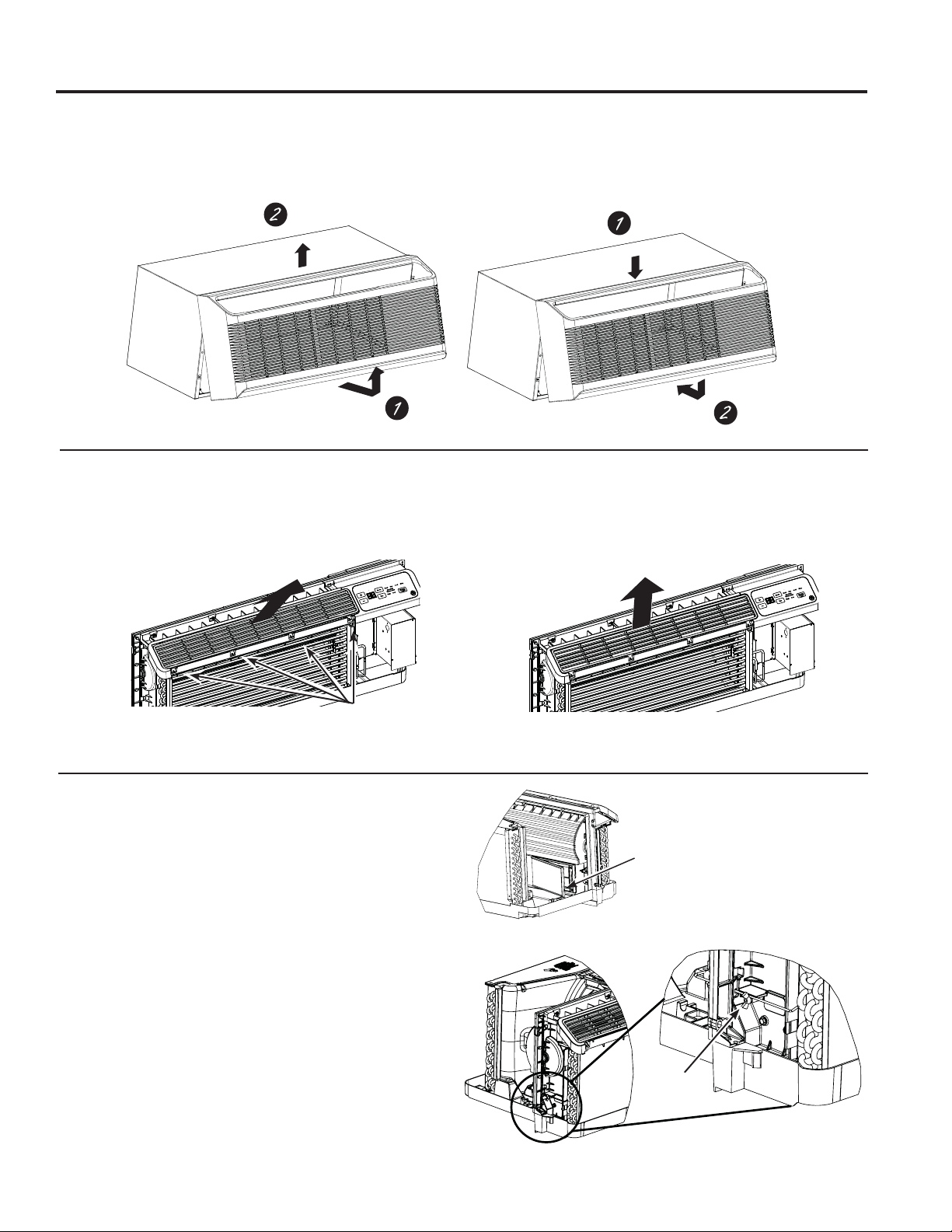
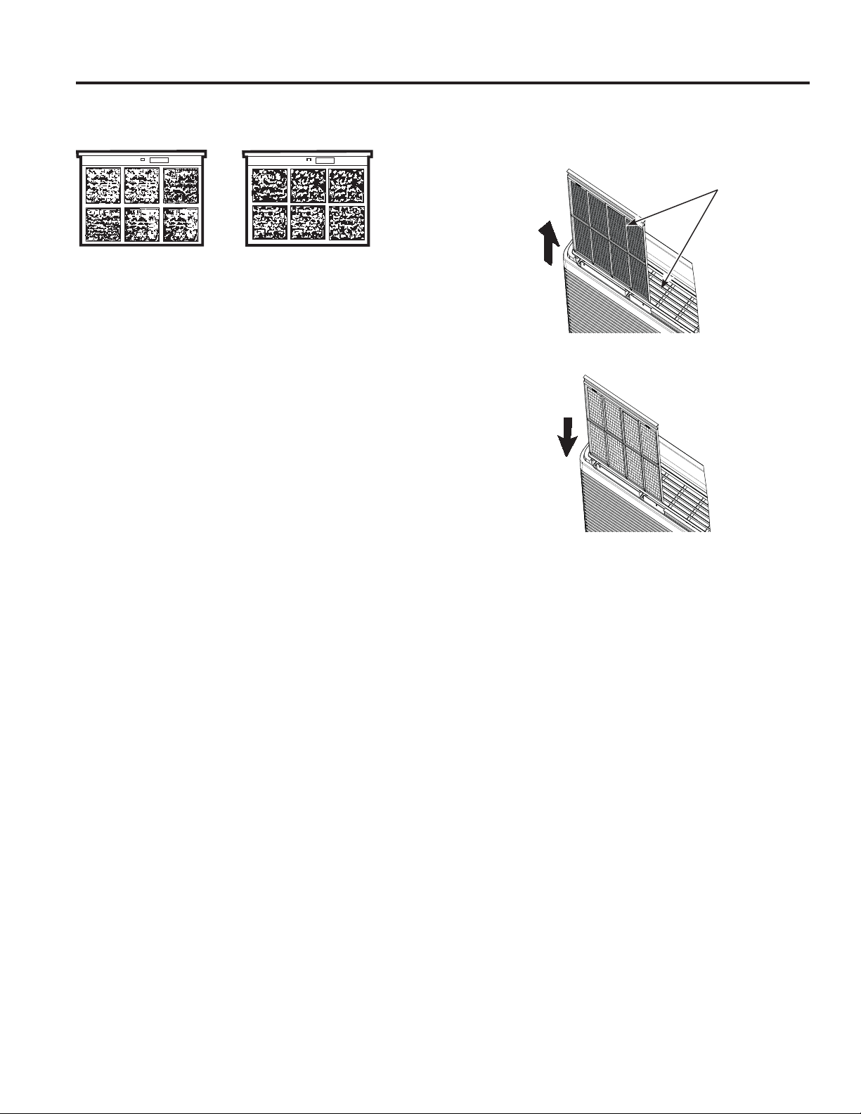
To clean the air filters:
Ŷ9DFXXPRIIWKHKHDY\VRLO
Ŷ5XQZDWHUWKURXJKWKHILOWHUVIURPWKH
back side.
Ŷ'U\WKRURXJKO\EHIRUHUHSODFLQJ
NOTE: 7KHDLUILOWHUVDUHLQWHUFKDQJHDEOHDQGZLOOILWLQ
either the right or left side.
To remove the air filters:
To replace the air filters:
NOTICE:
'RQRWRSHUDWHWKH=RQHOLQHZLWKRXWWKHILOWHUVLQSODFH,I
a filter becomes torn or damaged, it should be replaced
immediately.
Operating without the filters in place or with damaged
filters will allow dirt and dust to reach the indoor coil and
reduce the cooling, heating, airflow and efficiency of the
unit.
Replacement filters are available from your salesperson,
GE Appliances dealer, GE Appliances Service and Parts
Center or authorized Customer Care® servicers.
To maintain optimum performance, clean the filters at least every 30 days.
Air Filters
FRONT
FRONT
Dirty filter—
Needs cleaning
Clogged filter—
Greatly reduces cooling,
heating and airflow.
Pull up
Push down
49-7774
Installation Instructions
INSTALLATION INSTRUCTIONS
BEFORE YOU BEGIN
Read these instructions completely and carefully.
•
IMPORTANT – Save these
instructions for local inspector’s use.
•
IMPORTANT – Observe all
governing codes and ordinances.
• Note to Installer – Be sure to leave these
instructions with the owner.
• Note to Owner – Keep these instructions for
future reference.
• Proper installation is the responsibility of the
installer.
• Product failure due to improper installation is not
covered under the Warranty.
• You must use all supplied parts and use proper
installation procedures as described in these
instructions when installing this air conditioner.
Questions? Call 844-GE4-PTAC (or 844-434-7822 ) or Visit our Website at: GEAppliances.com
Phillips screwdriver
RU´1XWGULYHU
TOOLS YOU WILL NEED
NOTE – As with any mechanical device with moving
SDUWVWKLVXQLWZLOOKDYHDZHDULQSHULRG$)7(5
,167$//$7,21WKLVXQLWVKRXOGEHRSHUDWHGIRU
hours to achieve optimum efficiency.
AIR CONDITIONER BREAK-IN
PERIOD
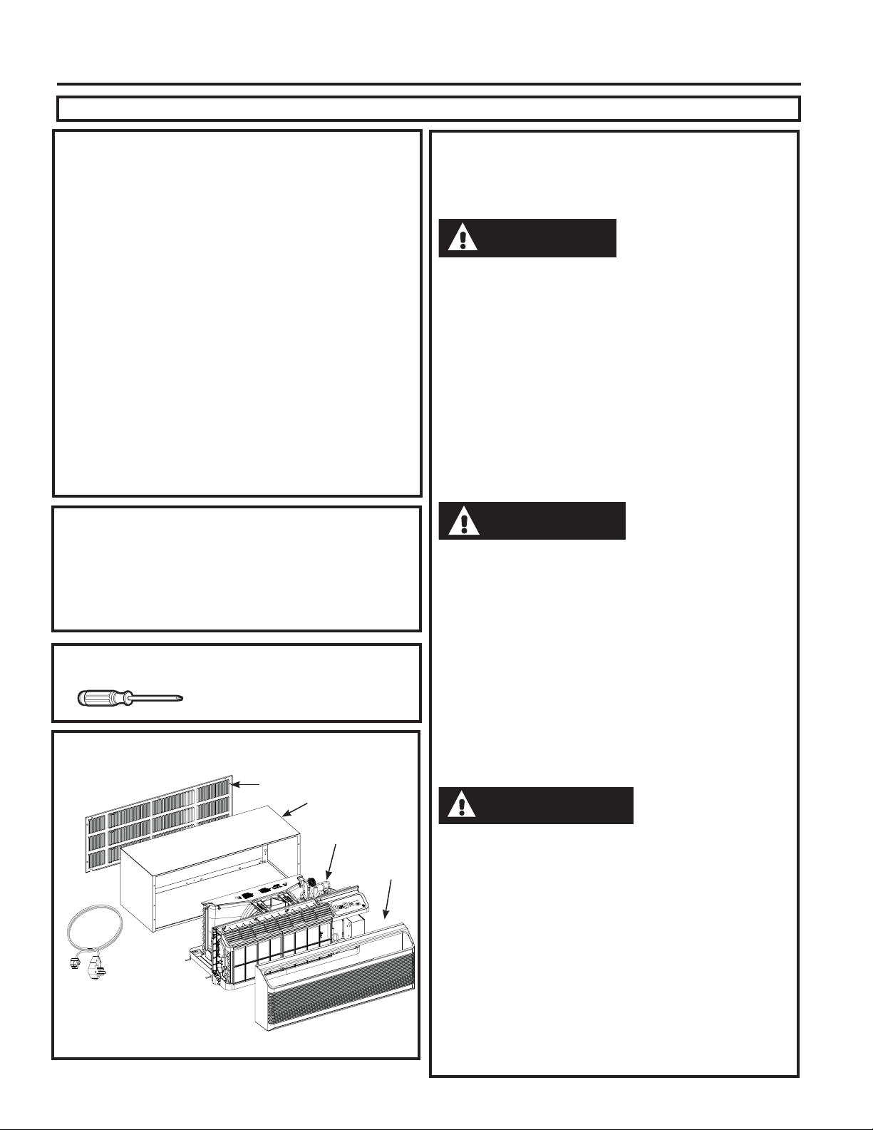
ZONELINE COMPONENTS
Appearance may vary.
*6KLSSHGZLWKWKH=RQHOLQHXQLW
&KHFNWKH³(VVHQWLDO(OHPHQWV´OLVW
on the unit located on front of the
base pan
([WHULRUJULOOHORXYHU
Wall case**
=RQHOLQHXQLW
Room
cover*
Power
supply kit**
IMPORTANT ELECTRICAL
SAFETY—
READ CAREFULLY
• Follow the National Electrical Code (NEC) or local codes
and ordinances.
• For personal safety, this Zoneline must be properly
grounded.
• Protective devices (fuses or circuit breakers) acceptable
for Zoneline installations are specified on the nameplate
of each unit.
• Do not use an extension cord with this unit.
• Aluminum building wiring may present special
problems—consult a qualified electrician.
• When the unit is in the OFF position, there is still voltage
to the electrical controls.
• Disconnect the power to the unit before servicing by:
1 Removing the power cord (if it has one) from the wall
receptacle. OR
2 Removing the branch circuit fuses or turning the
circuit breakers off at the panel.
• Suivez le Code national de l’électricité (CNE) ou vos
ordonnances et codes locaux.
• Pour votre sécurité personnelle, ce Zoneline doit être bien mis à la
terre.
• Les appareils protecteurs (fusibles ou disjoncteurs) acceptables
pour installer votre Zoneline sont indiqués sur la plaque signalé-
tique de chaque appar eil.
• N’utilisez jamais de rallonge électrique avec cet appareil.
/HV¿OVGHEkWLPHQWHQDOXPLQLXPSHXYHQWSRVHUGHVSUREOqPHV
SDUWLFXOLHUV²FRQVXOWH]XQpOHFWULFLHQTXDOL¿p
• Quand votre appareil est en position OFF (arrêt), il reste de la ten-
sion dans les commandes électriques.
• Débranchez le courant de votre appareil avant de l’entretenir ou
de le réparer en:
1. Enlevant le cordon d’alimentation (le cas échéant) de la prise
murale. OU
2. Enlevant les fusibles du circuit de dérivation ou en débran-
chant les disjoncteurs de dérivation au panneau.
• Siga las instrucciones del National Electrical Code (Código de
Electricidad Nacional) (NEC) o los códigos u ordenanzas locales.
•Para su seguridad personal, el acondicionador de aire Zoneline
debe tener una adecuada conexión a tierra.
• Los dispositivos de protección (fusibles o disyuntores) adecua-
GRVSDUDODVLQVWDODFLRQHVGH=RQHOLQHVHHQFXHQWUDQHVSHFL¿FD-
dos en la placa de cada unidad.
• No utilice un cable de extensión con esta unidad.
• El cableado de aluminio puede presentar problemas especiales:
FRQVXOWHDXQHOHFWULFLVWDFDOL¿FDGR
• Cuando la unidad se encuentra en la posición OFF (apagado),
todavía hay voltaje en los controles eléctricos.
• Antes de realizar reparaciones en la unidad, desconecte el sumi-
nistro de energía de la siguiente manera:
1 Retire el cable eléctrico (si posee uno) del receptáculo de la
pared. O
2 Retire los fusibles de la sección o apague el disyuntor desde el
panel.
CAUTION
ATTENTION
PRECAUCIÓN
49-7774
Installation Instructions
INSTALLATION INSTRUCTIONS
Use the correct wall case
7KLVXQLWis designed to be installed in a GE
$SSOLDQFHVSODVWLFRULQVXODWHGPHWDOZDOOFDVH7KLV
minimizes condensation from forming on the room side
of the case.
NOTE: 7KHUHDUHVHYHUDOH[WUDKROHVLQWKHXQLWVLGH
flanges for installation in wall cases other than GE
$SSOLDQFHV7RDYRLGGDPDJLQJWKHIODQJHLQVXODWLRQ
the installer should use an awl or other sharp tool to
puncture the insulation in the appropriate holes before
installing the attachment screws.
Use the correct outdoor grille
You should use the outdoor grilles shown on the
³(VVHQWLDO(OHPHQWV´ODEHORQWKHEDVHSDQ
•,IDQH[LVWLQJJULOOHLVQRWUHSODFHGFDSDFLW\DQG
efficiency will be reduced and the unit may fail to
operate properly or fail prematurely. A deflector
NLW5$.PD\EHXVHGZLWKJULOOHVWKDWZHUHQRW
GHVLJQHGIRU\RXUQHZ*($SSOLDQFHV=RQHOLQHV
7KH5$.FRQWDLQVDLUGHIOHFWRUVDQGJDVNHWV
WKDWPRXQWWRWKHXQLWWRGLUHFWWKHKRWH[KDXVWDLU
away from the air intake to allow the unit to function
properly. The grille must have a 65% minimum
free area (as calculated by ASHRAE). See the
Architects and Engineers Data Manual for more
detailed information.
• Any vertical deflectors in a non GE Appliances
H[LVWLQJUHDUJULOOHVKRXOGEHUHPRYHGWRGHFUHDVH
condenser air recirculation that can cause the unit
WR³VKRUWF\FOH´DQGOHDGWRSUHPDWXUHFRPSRQHQW
failure.
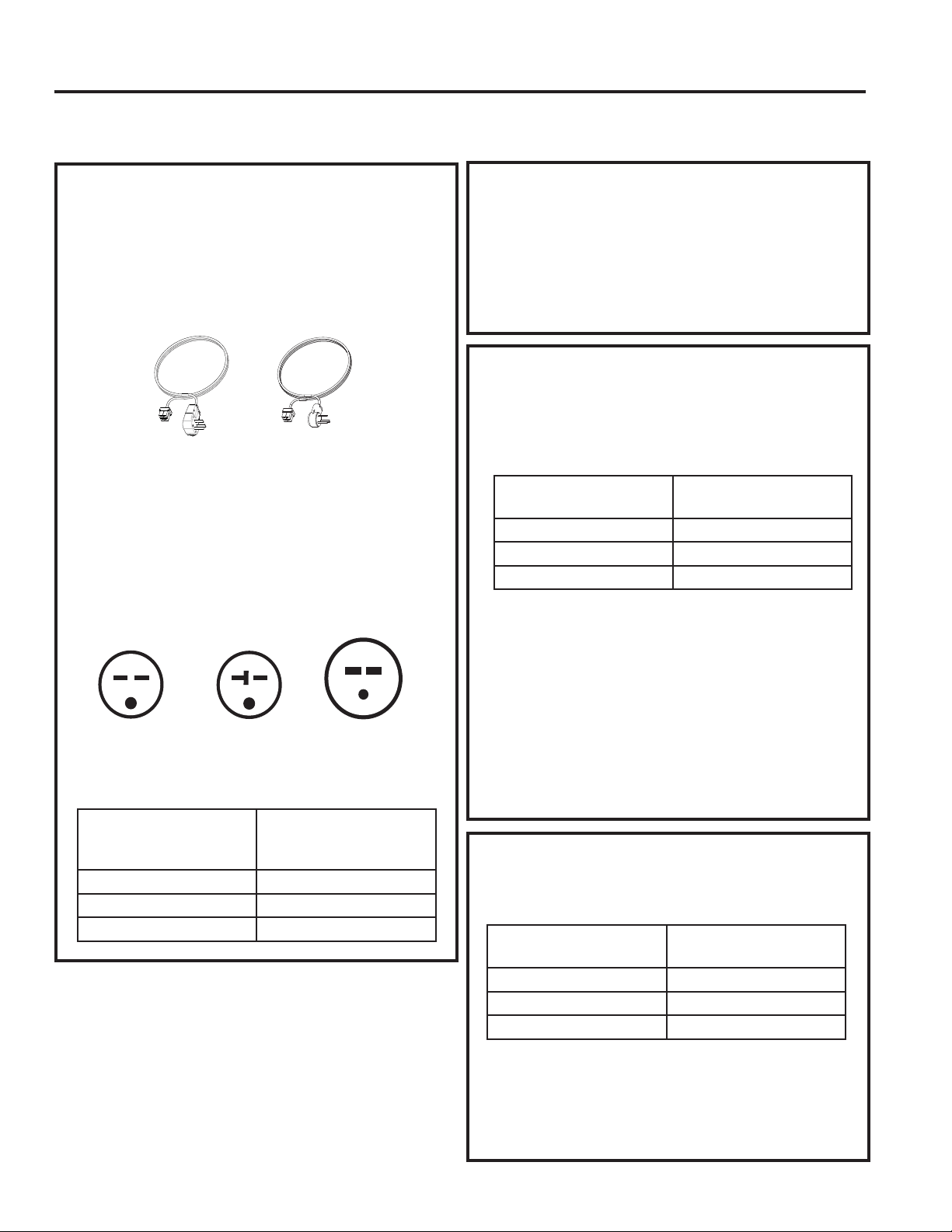
Use the correct power cord
/RFDOFRGHVPD\UHTXLUHWKHXVHRIDUFIDXOWRU
OHDNDJHFXUUHQWGHWHFWLRQGHYLFHVRQYROW
installations.
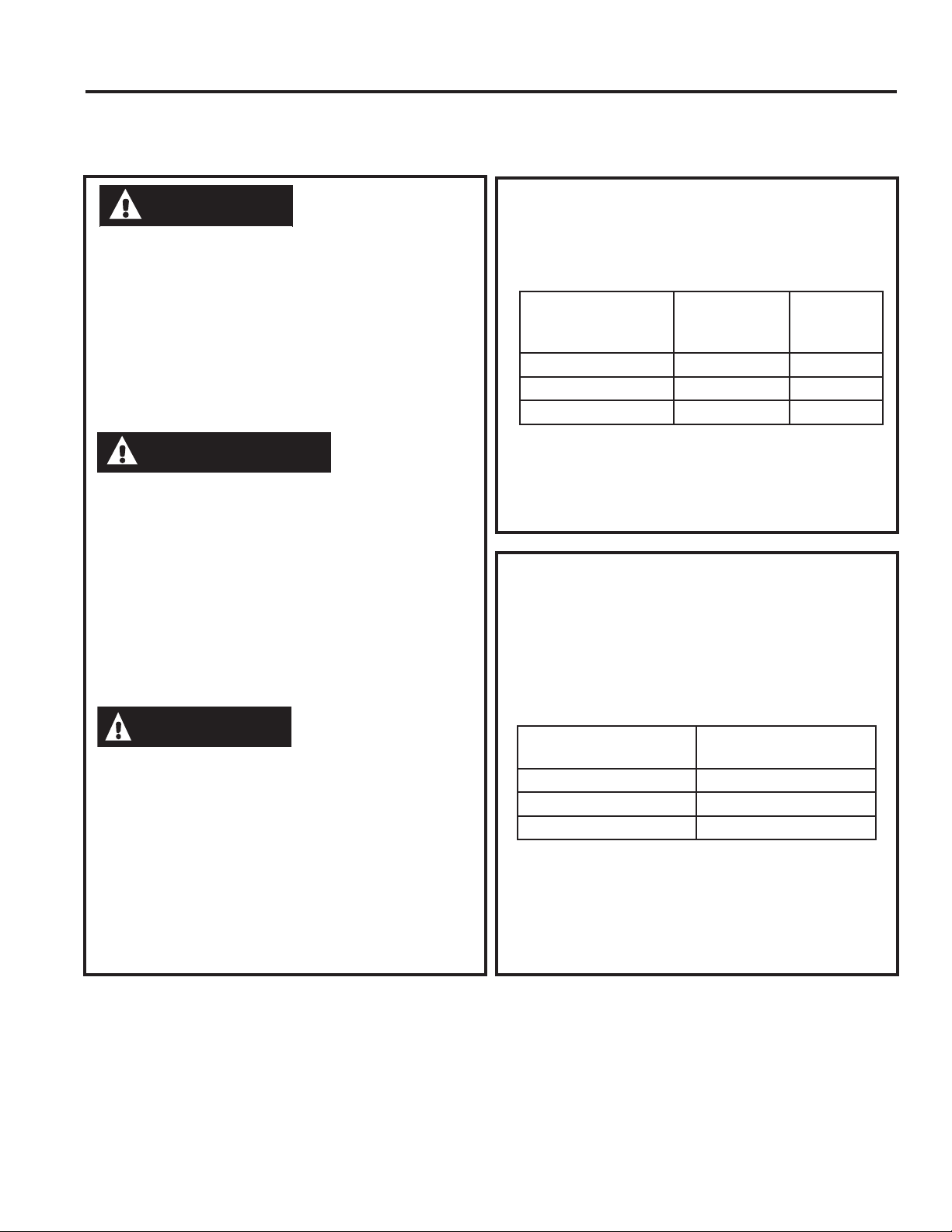
Replacing a ducted unit
New ducted installation:
,IWKLVXQLWLVWREHLQVWDOOHGLQDQHZGXFWHGDSSOLFDWLRQ
using a duct adapter kit, the kit must be installed before
WKHXQLWLVSODFHGLQWKHZDOOFDVH7KHLQVWDOODWLRQ
instructions are packed with the kit.
Duct kits available:
5$.
5$.%%
Existing ducted installation:
5HSODFHPHQWRIDQH[LVWLQJGXFWHGXQLWPD\UHTXLUH
different components. Request this information from
your sales representative. Duct seals on existing
unit need to be removed and added to the new
unit.
• Replacing 230/208 volt units:
6HHSDJH
• Replacing 265 volt units:
6HHSDJH
When using a duct kit, you must always turn Mode
7 to ON “ ”6HH0RGHLQVWUXFWLRQVRQSDJH
REPLACING AN EXISTING UNIT
Check the “Essential
(OHPHQWV´ODEHOIRU
important information.
Duct
Case
Mounting
plate
Duct Mode
Shown ON
49-7774
Installation Instructions
INSTALLATION INSTRUCTIONS
ELECTRICAL SUBBASE
CONNECTION
Power cords may include an arc fault
interruption or a leakage current detection
interruption device. A test and reset button is
provided on the plug case or the inline case.
The device should be tested on a periodic basis
by first pressing the TEST button and then the
RESET button. If the TEST button does not trip
or if the RESET button will not stay engaged,
discontinue use of the Zoneline and contact a
qualified service technician.
'HSHQGLQJRQDSSOLFDWLRQDSRZHUVXSSO\NLWZLWK/&',
PXVWEHXVHGWRVXSSO\SRZHUWRWKH=RQHOLQHXQLW7KH
appropriate kit is determined by the voltage, the means
of electrical connection and the amperage of the
branch circuit.
&RQQHFWLRQVRIRUYROWFLUFXLWVPD\EHZLWKD
SRZHUVXSSO\NLWRUDMXQFWLRQER[NLW
All wiring, including installation of the receptacle,
must be in accordance with the NEC and local
codes, ordinances and regulations. Codes require
the use of an arc fault or leakage current detection
GHYLFHRQWKHSRZHUFRUGH[FHSWGLUHFWFRQQHFW%H
sure to select the correct cord for your installation.
230/208 VOLT ELECTRICAL CONNECTION OPTIONS
POWER
CORD CONNECTION
DIRECT CONNECTION
2UGHUWKHIROORZLQJ.LWIRUYROWGLUHFW
FRQQHFWLRQDVUHTXLUHG
Review installation instructions provided with power
cord or direct connect kits for detailed assembly
instructions.
,IXVLQJDVXEEDVHFRQQHFWLRQWKH5$.&
-XQFWLRQ%R[LVDOVRQHFHVVDU\IRUDFRPSOHWH
installation.
Tandem
$PS
YROWUHFHSWDFOHFRQILJXUDWLRQ
Perpendicular
$PS
Large
Tandem
$PS
Power supply kit
(Appearance may vary)
YROWPRGHOVPD\EHLQVWDOOHGXVLQJRQHRI
WKHIROORZLQJHOHFWULFDOVXEEDVHV
Electrical subbases provide an enclosure for direct
FRQQHFWLRQRUHQFORVHGUHFHSWDFOHV7KHVXEEDVHNLW
includes the power cord.
7KHLQVWUXFWLRQVSURYLGHGZLWKWKHVHOHFWHGVXEEDVH
NLWPXVWEHFDUHIXOO\IROORZHG,WLVWKHUHVSRQVLELOLW\RI
the installer to ensure the connection of components
is done in accordance with these instructions and all
electrical codes.
,IXVLQJDVXEEDVHFRQQHFWLRQWKH5$.&
-XQFWLRQ%R[LVDOVRQHFHVVDU\IRUDFRPSOHWH
installation.
Branch Circuit and
Unit Amperage Rating
Proper GE Appliances
Power Cord
with LCDI Device
5$.3
5$.3
5$.3
Branch Circuit and
Unit Amperage Rating
Proper GE Appliances
Subbase Kit
5$.'3$
5$.'3$
5$.'3$
Branch Circuit and
Unit Amperage Rating
Power Supply Kit
5$.'
5$.'
5$.'
49-7774
Installation Instructions
INSTALLATION INSTRUCTIONS
265 VOLT ELECTRICAL CONNECTION OPTIONS
&RQQHFWLRQRIWKLV9$&SURGXFWWRDEUDQFKFLUFXLW
MUST be done by direct connection in accordance with
the National Electrical Code. Plugging this unit into a
EXLOGLQJPRXQWHGH[SRVHGUHFHSWDFOHLVQRW permitted by
code.
7KHVHPRGHOVPXVWEHLQVWDOOHGXVLQJWKHDSSURSULDWH
GE Appliances power supply kit for the branch circuit
amperage and the electrical resistance heater wattage
GHVLUHG8VHWKH32:(5&211(&7,21&+$57RQ
SDJHWRGHWHUPLQHWKHFRUUHFWNLWUHTXLUHG2QHRIWKH
IROORZLQJLQVWDOODWLRQPHWKRGVPXVWEHXVHG
9RXV'(9(=EUDQFKHUFHSURGXLWDOLPHQWpSDUFRXUUDQW
DOWHUQDWLIGHYROWVDXFLUFXLWGHGpULYDWLRQSDU
EUDQFKHPHQWGLUHFWFRQIRUPpPHQWDX&RGHQDWLRQDO
G¶pOHFWULFLWp/H&RGHQ¶DXWRULVHSDVOHEUDQFKHPHQ
WGHYRWUHDSSDUHLOjXQHSULVHH[SRVpHPRQWpHVXUOH
bâtiment.
9RXVGHYH]LQVWDOOHUFHVPRGqOHVjO¶DLGHGHODERQQH
WURXVVHG¶DOLPHQWDWLRQpOHFWULTXH*($SSOLDQFHVSRXU
O¶DPSpUDJHGXFLUFXLWGHGpULYDWLRQHWODSXLVVDQFHGX
FKDXIIDJHjUpVLVWDQFHpOHFWULTXHGpVLUpH8WLOLVH]OH
7DEOHDXGHFRQWDFWpOHFWULTXHSDJHSRXUGpWHUPLQHU
ODERQQHWURXVVHUHTXLVH9RXVGHYH]XWLOLVHUO¶XQHGHV
PpWKRGHVVXLYDQWHVG¶LQVWDOODWLRQ
/DFRQH[LyQGHHVWHSURGXFWRGHYROWLRVGH&$
a un circuito derivado DEBE realizarse mediante una
FRQH[LyQGLUHFWDGHDFXHUGRDODVLQGLFDFLRQHVGHO1(&
(OFyGLJRQRSHUPLWHHQFKXIDUHVWDXQLGDGDXQDFDMD
H[WHUQD
Estos modelos deben instalarse utilizando el kit de GE
Appliances de suministro de energía adecuado para el
DPSHUDMHGHFLUFXLWRGHULYDGR\HOYDWLDMHGHVHDGRSDUD
HOFDOHIDFWRUGHUHVLVWHQFLDHOpFWULFD8WLOLFHOD7$%/$
'(&21(;,21(6(/e&75,&$6HQODSiJLQDSDUD
determinar cuál es el kit necesario. Debe utilizarse uno
GHORVVLJXLHQWHVPpWRGRVGHLQVWDODFLyQ
A. FOR SUBBASE
INSTALLATION
(OHFWULFDOVXEEDVHNLWVDUHDYDLODEOHWRSURYLGHDIOH[LEOH
enclosure for direct connection.
7KHLQVWUXFWLRQVSURYLGHGZLWKWKHVHOHFWHGVXEEDVH
NLWPXVWEHFDUHIXOO\IROORZHG,WLVWKHUHVSRQVLELOLW\RI
the installer to ensure the connection of components
is done in accordance with these instructions and all
electrical codes.
B. FOR DIRECT CONNECT
INSTALLATION
,IDQHOHFWULFDOVXEEDVHLVQRWXVHGGLUHFWFRQQHFWLRQ
WREUDQFKFLUFXLWZLULQJLQVLGHWKHSURYLGHGMXQFWLRQER[
must be done in accordance with the following steps.
Order the following Kit for 265-volt direct connection
DVUHTXLUHG
Review installation instructions provided with power
cord or direct connect kits for detailed assembly
instructions.
WARNING
AVERTISSEMENT
ADVERTENCIA
Branch Circuit and
Unit Amperage Rating
Power Supply Kit
5$.'
5$.'
5$.'
Branch Circuit and
Unit Amperage
Rating
Proper GE
Appliances
Subbase Kit
Power
Supply Kit
5$.( 5$.3
5$.( 5$.3
5$.( 5$.3

49-7774
INSTALLATION INSTRUCTIONS
Installation Instructions
INSTALLATION INSTRUCTIONS
POWER CONNECTION CHART
Power Cord Connections
Direct Connections
230/208 Volt
Power Supply Kits
with Current Leakage
Detection Device (1)
Wall Plug
&RQ¿JHUDWLRQ Circuit Protective Device
Heater Wattage
@ 230/208 Volts
5$.363
5$.363
5$.363
7DQGHP
Perpendicular
/DUJH7DQGHP
$PS7LPH'HOD\)XVHRU%UHDNHU
$PS7LPH'HOD\)XVHRU%UHDNHU
$PS7LPH'HOD\)XVHRU%UHDNHU
.:
.:
.:+LJK)DQ
.:/RZ)DQ
230/208 Volt
Power Supply Kits (2)
Circuit Protective Device Heater Wattage
@ 230/208 Volts
5$.'
5$.'
5$.'
$PS7LPH'HOD\)XVHRU%UHDNHU
$PS7LPH'HOD\)XVHRU%UHDNHU
$PS7LPH'HOD\)XVHRU%UHDNHU
.:
.:
.:+LJK)DQ
.:/RZ)DQ
265 Volt
Power Supply Kits
Circuit Protective Device Heater Wattage
@ 265 Volts
5$.'
5$.'
5$.'
$PS7LPH'HOD\)XVHRU%UHDNHU
$PS7LPH'HOD\)XVHRU%UHDNHU
$PS7LPH'HOD\)XVHRU%UHDNHU
.:
.:
.:+LJK)DQ
.:/RZ)DQ
$MXQFWLRQER[LVLQFOXGHGZLWK63NLWV
$MXQFWLRQER[LVLQFOXGHGZLWKWKHVHNLWV
22 49-7774
INSTALLATION INSTRUCTIONS
Installation Instructions
1. INSTALL THE WALL
CASE AND EXTERIOR
GRILLE
7KH5$%$%VHULHVRU5$%$%ZDOOFDVH
must be properly installed per instructions packed
with the case.
• Remove the corrugated stiffener and the outdoor
SURWHFWLYHSDQHO8VHWKHVOLWLQWKHRXWGRRUSDQHO
as a hand hold and push out.
•,QVWDOOWKHH[WHULRUJULOOHIURPWKHURRPVLGH
following instructions packed with the grille.
NOTE: For installation with a subbase or duct
adapter, see the instructions packed with those kits.
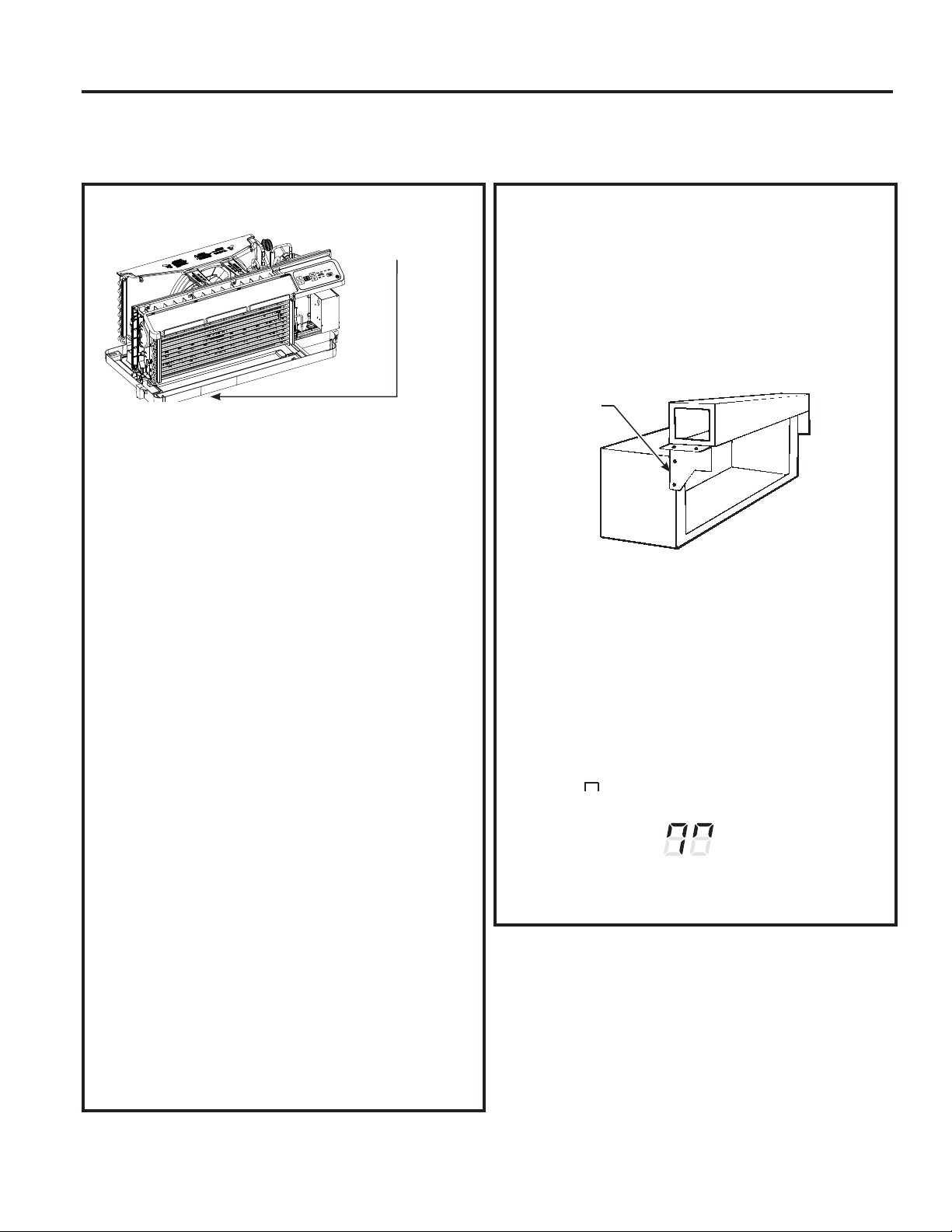
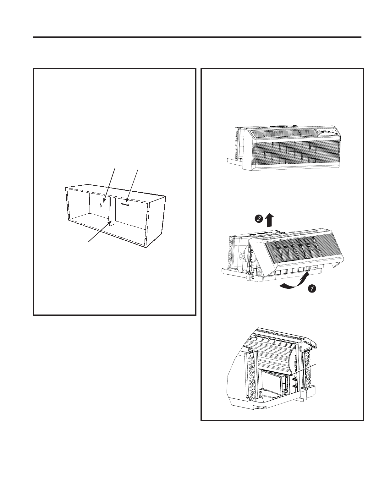
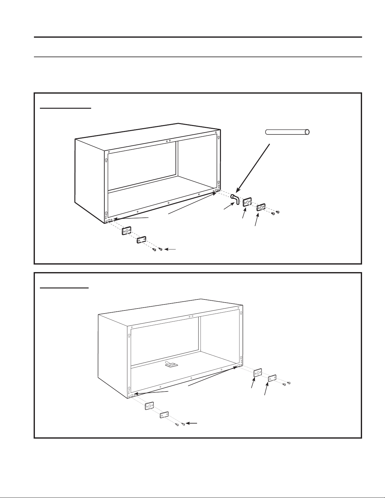
2. PREPARE THE UNIT
• Carefully remove the foam shipping blocks from
WKHURRPIURQWFRPSUHVVRUDQGRXWGRRUIDQ7KHUH
may be multiple blocks and pieces of shipping tape
that need to be removed.
• Remove the room cover by pulling it out at the
ERWWRPWRUHOHDVHLWWKHQOLIWLWXSWRFOHDUWKHUDLO
DORQJWKHXQLWWRS
•,IYHQWGRRULVWREHRSHUDWLRQDOUHPRYHVKLSSLQJ
screws from the front side of the vent door, if
present.
INSTALLING THE ZONELINE
Shipping tape
/RFDWLRQVPD\YDU\
Remove the
shipping screws
(if operation is
GHVLUHG
Stiffener
Protective
panel
Slit
49-7774 23
Installation Instructions
INSTALLATION INSTRUCTIONS
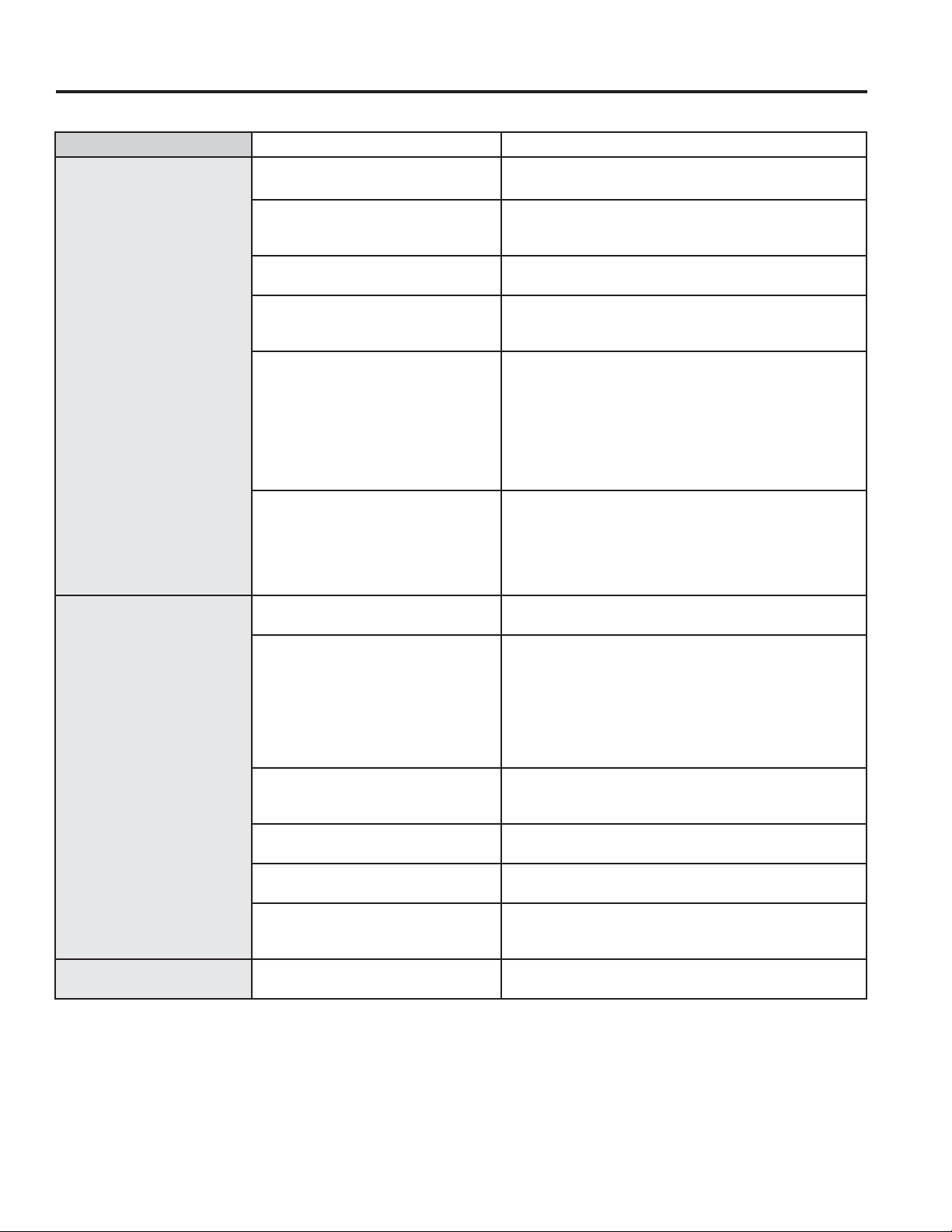
INSTALLING THE ZONELINE (cont.)
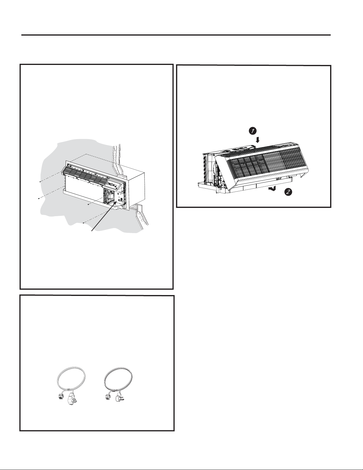
3. INSTALL THE UNIT
INTO THE WALL CASE
Slide the unit into the wall case and secure with four
screws through the unit flange holes.
7KHIRXUVFUHZVZLOOEHORFDWHGLQDVHDOHGEDJWKDW
sits under the control panel, sitting in the pocket in
the base pan.
5. REPLACE THE ROOM
FRONT
Reinstall the room cover by aligning and placing the
WRSUDLORIWKHURRPFRYHURYHUWKHFKDVVLVWKHQ
SXVKLQJLWLQDWWKHERWWRP
NOTE: 7KHUHDUHVHYHUDOH[WUDKROHVLQWKHXQLWVLGH
flanges for installation in wall cases other than GE
$SSOLDQFHV7RDYRLGGDPDJLQJWKHIODQJHLQVXODWLRQ
the installer should use an awl or other sharp tool
to puncture the insulation in the appropriate holes
before installing the attachment screws.
7KHIRXUZDOOFDVHVFUHZVZLOOEHWDSHG
WRWKHSRFNHWLQIURQWRIWKHFRQWUROER[
4.
CONNECT POWER
CORD OR DIRECT
CONNECT KIT
Review installation instructions provided with
power cord or direct connect kits for detailed
assembly instructions.
Power supply kit
(Appearance may vary)
49-7774
Installation Instructions
INSTALLATION INSTRUCTIONS
OPTIONAL—DRAIN KIT INSTALLATION
Dry Air 25 Series models are designed to improve dehumidification by 25%. Since more moisture will
be removed from the air, there is a greater possibility that water will drip from the wall case than with a
standard unit. To prevent this water from dripping onto external building walls, we recommend the use of
RAD10 Drain Kit.
External Drain
6HHWKH,QVWDOODWLRQ,QVWUXFWLRQV
LQWKH5$'NLW
Internal Drain
6HHWKH,QVWDOODWLRQ,QVWUXFWLRQV
LQWKH5$'NLW
7\SH³$´VFUHZIRUPHWDOFDVHRU
7\SH³%´VFUHZIRUPROGHGFDVH
Square
drain holes
Square
drain holes
Neoprene sponge gasket
Steel mounting plate
´2'GUDLQWXEH
Neoprene sponge gasket
Steel mounting plate
7\SH³$´VFUHZIRUPHWDOFDVHRU
7\SH³%´VFUHZIRUPROGHGFDVH
$OWHUQDWH
´ORQJ´2'
straight copper tube
7KHGUDLQLVORFDWHGXQGHUWKHFDELQHW
ORFDWLRQWREHGHWHUPLQHGLQWKHILHOG
49-7774 25
TROUBLESHOOTING TIPS
Troubleshooting Tips... Before you call for service
Save time and money! Review the charts on the following pages first and you may not need to call for service.
Problem Possible Cause What To Do
Zoneline does not start. The unit is unplugged. 0DNHVXUHWKH=RQHOLQHSOXJLVSXVKHGFRPSOHWHO\LQWR
the outlet.
The power cord is not firmly
attached.
Remove the room cover and make sure that the
black connector on the end of the ower cord is firmly
engaged.
The fuse is blown/circuit breaker
is tripped.
&KHFNWKHKRXVHIXVHFLUFXLWEUHDNHUER[DQGUHSODFH
the fuse or reset the breaker.
The unit is waiting for the
compressor overload protector to
reset.
7KLVLVQRUPDO7KH=RQHOLQHZLOOVWDUWDJDLQDIWHULW
resets.
Power Failure. ,ISRZHUIDLOXUHRFFXUVVHWWKHPRGHFRQWUROWROFF.
When power is restored, set the mode control to the
desired setting.
7KHUHLVDSURWHFWLYHWLPHGHOD\XSWRPLQXWHVWR
prevent tripping of the compressor overload. For this
reason, the unit may not start normal heating or cooling
for 3 minutes after it is turned back on.
The power cord current interrupter
devise is tripped.
3UHVVWKH5(6(7EXWWRQORFDWHGRQWKHSRZHUFRUG
SOXJRUWKHER[QHDUWKHSOXJ
,IWKH5(6(7EXWWRQZLOOQRWVWD\HQJDJHGGLVFRQWLQXH
XVHRIWKH=RQHOLQHDQGFRQWUDFWDTXDOLILHGVHUYLFH
technician.
Zoneline does not cool or
heat as it should.
Indoor airflow is restricted. Make sure there are not curtains, blinds or furniture
EORFNLQJWKHIURQWRIWKH=RQHOLQH
Outdoor airflow is restricted or
recirculated.
0DNHVXUHWKHUHDUJULOOHLVQRWUHVWULFWHG7KLVFDQ
cause the unit to cycle off due to the compressor
overload protector.
Outdoor grille must have a minimum of 65% free area.
Non-GE Appliances grills may be too restrictive for
proper performance. Consult your salesperson for
assistance.
The temp control may not be set
properly.
7XUQWKHFRQWUROWRWKHORZHURUKLJKHUVHWWLQJ
NOTE: 7KHWHPSHUDWXUHOLPLWHUPD\EHOLPLWLQJWKH
temperature range.
The air filter is dirty. &KDQJHWKHILOWHUDWOHDVWHYHU\GD\V6HHWKH&DUH
and Cleaning section
The room may have been hot or
cold.
:KHQWKH=RQHOLQHLVILUVWWXUQHGRQ\RXQHHGWRDOORZ
time for the room to cool down or warm up.
Outdoor air is entering the room. Set the vent control to the closed position.
127(8QLWVHTXLSSHGZLWKPDNHXSYHQWLODWLRQZLOO
continuously allow some outdoor air into the room.
Burning odor at the start
of heating operation.
Dust on the surface of the heating
elements.
7KLVFDQFDXVHD³EXUQLQJ´RGRUDWWKHEHJLQQLQJRIWKH
KHDWLQJRSHUDWLRQ7KLVVKRXOGTXLFNO\IDGH
26 49-7774
TROUBLESHOOTING TIPS
Troubleshooting Tips... Before you call for service
Save time and money! Review the charts on the following pages first and you may not need to call for service.
Problem Possible Cause What To Do
The air is not always cool
or hot during operation.
The heat pump is not producing
hot air.
7KLVLVQRUPDO7KHKHDWSXPSZLOOSURGXFHZDUPDLU
but not as hot as air produced when the higher-cost
electric heat is used.
The Smart Fan Auxiliary control
may be set to continuous fan.
7KLVFDXVHVWKHIDQWREORZURRPWHPSHUDWXUHDLU
HYHQZKHQWKHFRPSUHVVRURUKHDWHUF\FOHVRII7KH
continuous air movement provides better overall
temperature control in the cool mode. See Smart Fan-
&RROLQJ+HDWLQJVHFWLRQRQSDJH
The air does not feel warm
enough during heating
operation
The heat pump alone produces air
that feels cooler than desired.
8VHWKH(OHFWULF+HDW2SWLRQ7KLVWXUQVRIIWKHKHDW
pump and warms with electric heat only.
NOTE:8VHRIWKLVRSWLRQZLOOUHVXOWLQLQFUHDVHG
energy consumption.
The unit is not blowing
out air
The Smart Fan Auxiliary Controls
may be set to cycle.
6HH6PDUW)DQ&RROLQJ+HDWLQJVHFWLRQRQSDJH
The electric heating and
fan features do not work
The power cord is not firmly
attached.
Remove the room cover and make sure that the
black connector on the end of the power cord is firmly
engaged.
Temperature display
flashes
The compressor may have failed. Set the operation control to OFF and then restart the
XQLW,IWKHIODVKLQJOLJKWUHDSSHDUVZLWKLQPLQXWHV
call for service.
The unit does not function
after installing Remote
Wall Thermostat
Aux Mode 6 not set properly.
9HULI\ZLULQJIURP5HPRWH:DOO7KHUPRVWDWLVFRUUHFWWR
unit thermostat connector.
Unit thermostat connections are
incorrect.
&KHFN$X[0RGHWREHVXUHVZLWFKRQ³RQ´IRU
5HPRWH7KHUPRVWDWVHHSDJH
Transformer resets or opens with
short.
Wait 5 minutes to see if power resets.
Heat pump operates with
electric heat only during
heating.
Aux Mode 6 not set properly. &KHFN$X[0RGHLVVHWIRUWKHDSSURSULDWHUHPRWH
ZDOOWKHUPRVWDWHLWKHU³³IRU³FRROKHDW´RU³³IRU
³$XWR&KDQJH2YHU´VHHSDJH
Aux Mode 8 not set properly. &KHFN$X[0RGHWREHVXUHVZLWFKLV³RII´IRUKHDW
SXPSRSHUDWLRQVHHSDJH
49-7774 27
Things that are normal
TROUBLESHOOTING TIPS
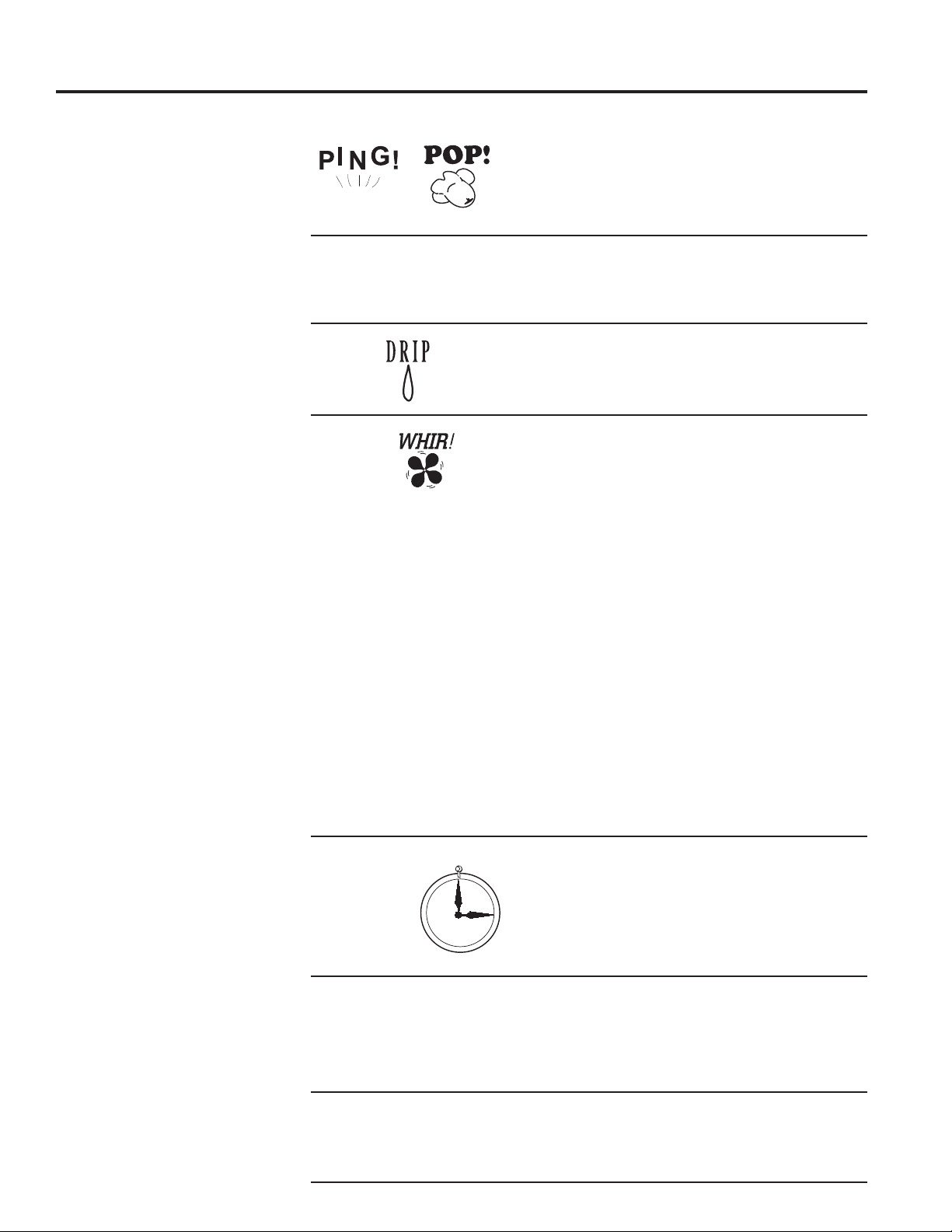
Normal Operating Sounds
You may hear a pinging noise caused by water
being picked up and thrown against the condenser
RQUDLQ\GD\VRUZKHQWKHKXPLGLW\LVKLJK7KLV
design feature helps remove moisture and improve
efficiency.
You may hear relays click when the controls cycle
RQDQGRIIRUDUHDGMXVWHGWRFKDQJHWKHURRP
temperature.
Water will collect in the base pan during high
KXPLGLW\RURQUDLQ\GD\V7KHZDWHUPD\RYHUIORZ
and drip from the outdoor side of the unit.
7KHLQGRRUIDQUXQVFRQWLQXRXVO\ZKHQWKHXQLWLV
operating in the cooling mode, unless the Smart
)DQ$X[LOLDU\&RQWUROLVVHWWRF\FOH7KLVZLOOFDXVH
the fan to cycle on and off with the compressor.
You may also hear a fan noise stop and start.
7KHUHDUHWLPHVZKHQWKHIDQRQWKHXQLWZLOOUXQ
HYHQZKHQWKHXQLWLVQRWKHDWLQJRUFRROLQJ,IWKH
system is set up to be in continuous fan the indoor
fan will run regardless if the unit may be cooling or
heating. Other times the fan will run longer than
WKHKHDWLQJFRROLQJF\FOHRUNLFNRQRFFDVLRQDOO\
7KLVLVQRUPDODQGLVGRQHWRLPSURYHURRPFRPIRUW
and balance.
,IWKHXQLWLVHTXLSSHGZLWKDPDNHXSDLUYHQWLODWLRQ
system, fans will run continuously.
Digital makeup air unit will perform a system check
upon power up, power cycle, and once every 7
GD\VLIWKHXQLWLVLQRFFXSDQF\PRGH7KHV\VWHP
FKHFNODVWVDSSUR[LPDWHO\VHFRQGV'XULQJWKLV
time the fans will speed up, slow down and then go
to the set point.
You may notice a few minutes delay in starting if
\RXWU\WRUHVWDUWWKH=RQHOLQHWRRVRRQDIWHUWXUQLQJ
LWRIIRULI\RXDGMXVWWKHWKHUPRVWDWULJKWDIWHUWKH
FRPSUHVVRUKDVVKXWRII7KLVLVGXHWRDEXLOWLQ
restart protector for the compressor that causes
a 3-minute delay.
During the defrost cycle, both indoor and outdoor
fans stop and the compressor will operate in the
cooling mode to remove frost from the outdoor coil.
After defrost, the unit will restart in electric heat to
quickly warm the room to the desired comfort level.
7RSURWHFWWKHFRPSUHVVRUDQGSUHYHQWVKRUW
cycling, the unit is designed to run for a minimum
of 3 minutes after the compressor starts at any
thermostat setting.
3-Minute
Delay
³&/,&.´
S,/ENCE
COMPRESSOR
3527(&7,21

28 49-7774
Notes
NOTES
49-7774 29
CONSUMER SUPPORT
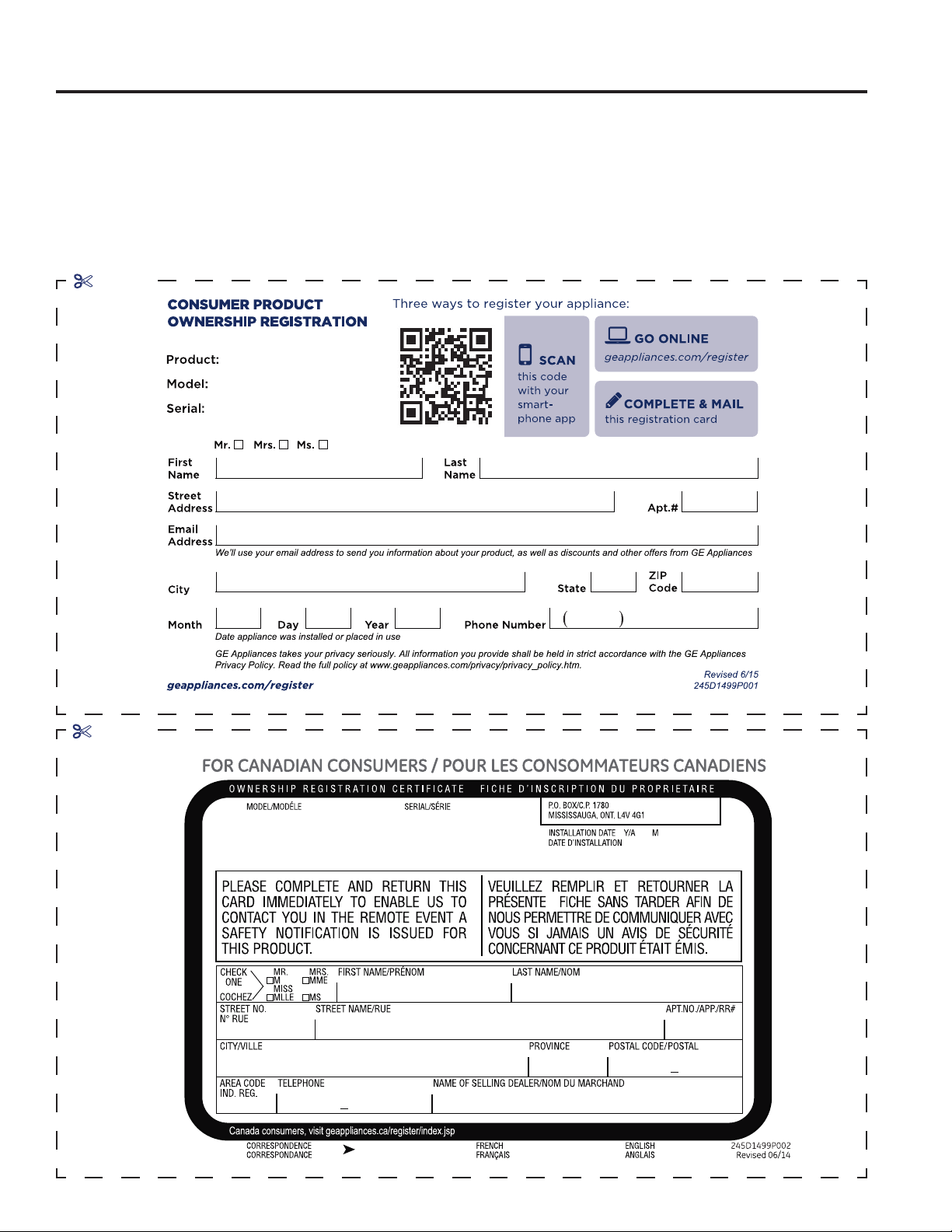
Product Registration
Complete and mail your
Consumer Production
Registration today. Have
the peace of mind of
knowing we can contact you
in the unlikely event of a
VDIHW\PRGL¿FDWLRQ
After mailing the registration
below, store this document in
DVDIHSODFH,WFRQWDLQVLQIRU-
mation you will need should
you require service. Our
service number is *(
37$&RU.
Read your Owner’s
0DQXDOFDUHIXOO\,WZLOO
help you operate your
new appliance properly.
Follow these three steps to protect your new appliance investment:
23
cut here
cut here
49-7774
CONSUMER SUPPORT
Product Registration
Please place in envelope and mail to:
Please place in envelope and mail to:
Veuillez mettre dans une enveloppe et envoyez à :
49-7774
ACCESSORIES
GE Appliances Zoneline Warranty
Ŷ Service trips to your site to teach you how to use
the product.
Ŷ Improper installation, delivery or maintenance.
n If you have an installation problem, or if the air
conditioner is of improper cooling capacity for the
intended use, contact your dealer or installer. You
are responsible for providing adequate electrical
connecting facilities.
Ŷ In commercial locations, labor necessary to move
the unit to a location where it is accessible for
service by an individual technician.
Ŷ Failure or damage resulting from corrosion due to
installation in an environment containing corrosive
chemicals.
Ŷ Replacement of fuses or resetting of circuit
breakers.
Ŷ Failure of the product resulting from modifications
to the product or due to unreasonable use,
including failure to provide reasonable and necessary
maintenance.
Ŷ Failure or damage resulting from corrosion due
to installation in a coastal environment, except
for models treated with special factory-applied
anti-corrosion protection as designated in
the model number.
Ŷ Damage to product caused by improper power
supply voltage, accident, fire, floods or acts of God.
Ŷ Incidental or consequential damage to personal
property caused by possible defects with this air
conditioner.
Ŷ Damage caused after delivery.
Ŷ Product not accessible to provide required service.
What GE Will Not Cover:
7KLVZDUUDQW\LVH[WHQGHGWRWKHRULJLQDOSXUFKDVHUDQGDQ\VXFFHHGLQJRZQHUIRUSURGXFWV
SXUFKDVHGIRUXVHZLWKLQWKH86$DQG&DQDGD,IWKHSURGXFWLVORFDWHGLQDQDUHDZKHUHVHUYLFH
by a GE Appliances Authorized Servicer is not available, you may be responsible for a trip charge
or you may be required to bring the product to an Authorized GE Appliances Service location for
VHUYLFH,Q$ODVNDWKHZDUUDQW\H[FOXGHVWKHFRVWRIVKLSSLQJRUVHUYLFHFDOOVWR\RXUVLWH
6RPHVWDWHVRUSURYLQFHVGRQRWDOORZWKHH[FOXVLRQRUOLPLWDWLRQRILQFLGHQWDORUFRQVHTXHQWLDO
GDPDJHV7KLVZDUUDQW\JLYHV\RXVSHFLILFOHJDOULJKWVDQG\RXPD\DOVRKDYHRWKHUULJKWVZKLFK
YDU\IURPVWDWHWRVWDWHRUSURYLQFHWRSURYLQFH7RNQRZZKDW\RXUOHJDOULJKWVDUHFRQVXOW\RXU
local, state or provincial consumer affairs office or your state’s Attorney General.
Warrantor: GE Appliances, a Haier company
All warranty service provided by our Factory Service Centers or an authorized Customer Care
®
WHFKQLFLDQ7R
schedule service, on-line, visit us at GEAppliances.com, or call *(37$&RU)RUVHUYLFH
LQ&DQDGDFRQWDFW*RUGRQ:LOOLDPV&RUSDW3OHDVHKDYHVHULDOQXPEHUDQGPRGHOQXPEHU
availa ble when calling for service.
EXCLUSION OF IMPLIED WARRANTIES—Your sole and exclusive remedy is product repair as provided
in this Limited Warranty. Any implied warranties, including the implied warranties of merchantability or
fitness for a particular purpose, are limited to one year or the shortest period allowed by law.
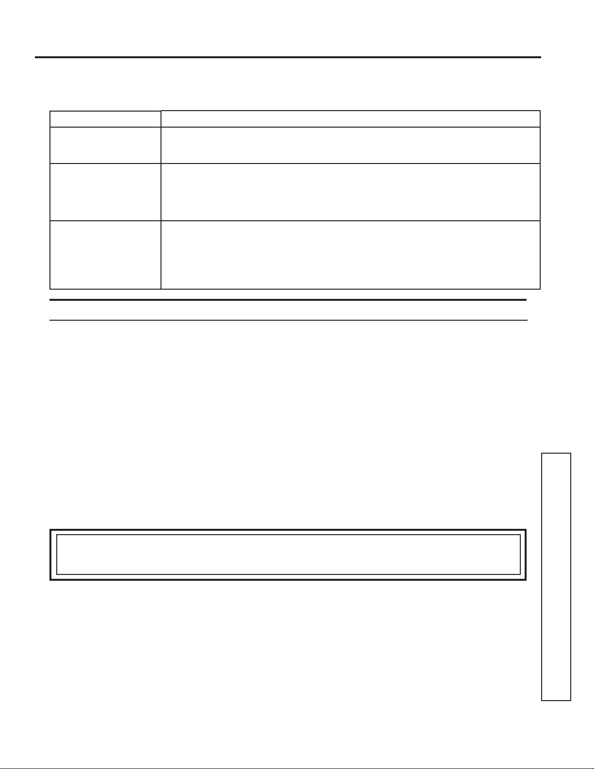
For The Period Of: GE Will Replace:
One Year
From the date of the
original purchase
Any part of the air conditioner which fails due to a defect in materials or workmanship.
During this limited one-year warranty, GE will provide, free of charge, all labor and
related service cost to replace the defective part.
Five Year
From the date of the
original purchase
Sealed Refrigerating System, if any part of the sealed refrigerating system (the
compressor, condenser, evaporator and all connecting tubing including the make up
DLUV\VWHPVKRXOGIDLOGXHWRDGHIHFWLQPDWHULDOVRUZRUNPDQVKLS'XULQJWKLVlim-
ited five-year warranty, GE will provide, free of charge, all labor and related service
cost to replace the defective part.
Second through
Fifth Year
From the date of the
original purchase
Fan Motors, Switches, Thermostat, Heater, Heater Protectors, Compressor
Overload, Solenoids, Circuit Boards, Auxiliary Controls, Thermistors, Freeze
Sentinel, Frost Controls, ICR Pump, Capacitors, Varistors and Indoor Blower
Bearings, if any of these parts should fail due to a defect in materials or workmanship.
During this additional four-year limited warranty, the customer will be responsible
for any labor and related service costs.
Staple your receipt here. Proof of the original purchase
date is needed to obtain service under the warranty.

32 49-7774
3ULQWHGLQWKH8QLWHG6WDWHV
Consumer Support
CONSUMER SUPPORT
GE Appliances Website
+DYHDTXHVWLRQRUQHHGDVVLVWDQFHZLWK\RXUDSSOLDQFH"7U\WKH*($SSOLDQFHV:HEVLWHKRXUVDGD\DQ\GD\
of the year! You can also shop for more great GE Appliances products and take advantage of all our on-line support
VHUYLFHVGHVLJQHGIRU\RXUFRQYHQLHQFH,QWKH86GEAppliances.com
Register Your Appliance
5HJLVWHU\RXUQHZDSSOLDQFHRQOLQHDW\RXUFRQYHQLHQFH7LPHO\SURGXFWUHJLVWUDWLRQZLOODOORZIRUHQKDQFHG
communication and prompt service under the terms of your warranty, should the need arise. You may also mail in
WKHSUHSULQWHGUHJLVWUDWLRQFDUGLQFOXGHGLQWKHSDFNLQJPDWHULDO,QWKH86GEAppliances.com/register
Schedule Service
([SHUW*($SSOLDQFHVUHSDLUVHUYLFHLVRQO\RQHVWHSDZD\IURP\RXUGRRU*HWRQOLQHDQGVFKHGXOH\RXUVHUYLFHDW
\RXUFRQYHQLHQFHDQ\GD\RIWKH\HDU,QWKH86GEAppliances.com/ge/service-and-support/service.htm
RUFDOOGXULQJQRUPDOEXVLQHVVKRXUV
Extended Warranties
3XUFKDVHD*($SSOLDQFHVH[WHQGHGZDUUDQW\DQGOHDUQDERXWVSHFLDOGLVFRXQWVWKDWDUHDYDLODEOHZKLOH\RXU
warranty is still in effect. You can purchase it on-line anytime. GE Appliances Services will still be there after your
ZDUUDQW\H[SLUHV,QWKH86GEAppliances.com/ge/service-and-support/shop-for-extended-service-plans.htm
RUFDOOGXULQJQRUPDOEXVLQHVVKRXUV
Remote Connectivity
)RUDVVLVWDQFHZLWKZLUHOHVVQHWZRUNFRQQHFWLYLW\IRUPRGHOVZLWKUHPRWHHQDEOH
visit our website at GEAppliances.com/ge/connected-appliances/RUFDOOLQWKH86
Parts and Accessories
,QGLYLGXDOVTXDOLILHGWRVHUYLFHWKHLURZQDSSOLDQFHVFDQKDYHSDUWVRUDFFHVVRULHVVHQWGLUHFWO\WRWKHLUKRPHV
9,6$0DVWHU&DUGDQG'LVFRYHUFDUGVDUHDFFHSWHG2UGHURQOLQHWRGD\KRXUVHYHU\GD\
,QWKH86GEApplianceparts.com or by phone at 877.959.8688 during normal business hours.
Instructions contained in this manual cover procedures to be performed by any user. Other servicing
generally should be referred to qualified service personnel. Caution must be exercised, since improper
servicing may cause unsafe operation.
Contact Us
,I\RXDUHQRWVDWLVILHGZLWKWKHVHUYLFH\RXUHFHLYHIURP*($SSOLDQFHVFRQWDFWXVRQRXU:HEVLWHZLWKDOOWKH
GHWDLOVLQFOXGLQJ\RXUSKRQHQXPEHURUZULWHWR
,QWKH86*HQHUDO0DQDJHU&XVWRPHU5HODWLRQV_*($SSOLDQFHV$SSOLDQFH3DUN_/RXLVYLOOH.<
GEAppliances.com/ge/service-and-support/contact.htm

Escriba los números de modelo y
de serie aquí:
Nº de Modelo ____________
Nº de Serie ______________
Encontrar estos números en una
etiqueta detrás de la cubierta en la
habitación bandeja de la base.
GE Appliances es una marca registrada de la Empresa General Electric. Fabricado bajo licencia de la marca registrada.
MANUAL DEL
PROPIETARIO
ACONDICIONADOR DE AIRE
Zoneline
®
49-7774 05-17 GEA
AZ45
AZ65
INFORMACIÓN DE SEGURIDAD ...3
USO DEL ZONELINE
Controles .............................4
Para Retirar la Tapa del Acondicionador
de Aire de Pared .....................5
Dirección del Aire .....................5
Control de la Ventilación ...............5
Controles Auxiliares ....................6
Termostato Remoto ...................10
Aire de Reposición .................... 11
CUIDADO Y LIMPIEZA
Tapa y Caja del Acondicionador
de Aire de Pared ....................12
Bobinas Externas .....................12
Bandeja de la Base ....................12
Filtro de la Ventilación ................13
Filtros de Aire ........................13
INSTRUCCIONES DE INSTALACIÓN
Preparación ..........................14
Reemplazo de una Unidad Existente ....15
Conexión Eléctrica ....................16
Instalación del Zoneline ...............19
Kit de Drenaje Opcional ...............21
CONSEJOS PARA LA SOLUCIÓN
DE PROBLEMAS .................22
Sonidos Normales de Funcionamiento . . 24
SOPORTE AL CLIENTE
Garantía .............................25
Soporte al Cliente ................... 26
2 49-7774
GRACIAS POR HACER QUE GE APPLIANCES SEA PARTE DE SU HOGAR.
Ya sea que haya crecido usando GE Appliances, o que ésta es su primera vez, nos complace
tenerlo en la familia.
Sentimos orgullo por el nivel de arte, innovación y diseño de cada uno de los electrodomésticos de
GE Appliances, y creemos que usted también. Entre otras cosas, el registro de su electrodoméstico
asegura que podamos entregarle información importante del producto y detalles de la garantía
cuando los necesite.
Registre su electrodoméstico GE ahora a través de Internet. Sitios Web y números telefónicos útiles
están disponibles en la sección de Soporte para el Consumidor de este Manual del Propietario.
También puede enviar una carta en la tarjeta de inscripción preimpresa que se incluye con
el material embalado.
49-7774 3
SAFETY INFORMATION
LEA Y GUARDE ESTAS INSTRUCCIONES
INFORMACIÓN IMPORTANTE DE SEGURIDAD
LEA TODAS LAS INSTRUCCIONES ANTES DE USAR
Para su seguridad, se debe seguir la información de este manual para minimizar el riesgo de incendio o
explosión, descargas eléctricas, o para evitar daños a la propiedad, lesiones personales o la muerte.
PRECAUCIONES DE SEGURIDAD
Ŷ$QWHVGHLQLFLDUVXXVRHODFRQGLFLRQDGRUGHDLUH=RQHOLQHGHEHLQVWDODUVHFRUUHFWDPHQWHVHJ~QODV
Instrucciones de instalación. Ver las Instrucciones de instalación en la parte trasera de este manual.
Ŷ5HHPSODFHLQPHGLDWDPHQWHWRGRVORVFDEOHVHOpFWULFRVTXHVHKD\DSHODGRRTXHVHKD\DQGDxDGR
de alguna otra manera. Un cable de corriente dañado no debe repararse, sino que debe ser
sustituido por uno nuevo que se adquiera del fabricante. No use un cable eléctrico que muestre
evidencias de deterioro o daños de abrasión en su superficie o en cualquiera de sus enchufes o
extremos.
Ŷ'HVHQFKXIHRGHVFRQHFWHHO=RQHOLQHGHVGHODFDMDGHIXVLEOHVRHOGLV\XQWRUDQWHVGHUHDOL]DU
cualquier tipo de reparación.
NOTA: Recomendamos enérgicamente que cualquier servicio llevado a cabo en este equipo lo realice
un individuo calificado.
Ŷ/RVVLVWHPDVGHDFRQGLFLRQDGRUGHDLUH5$UHTXLHUHQTXHORVFRQWUDWLVWDV\WpFQLFRVXWLOLFHQ
herramientas, equipamiento y normas de seguridad aprobadas para su uso con este refrigerante.
NO utilice equipamiento certificado sólo para refrigerante R22.
¿Desea reemplazar una unidad ya instalada?
Para más detalles, ver las Instrucciones de instalación en este manual.
ADVERTENCIA
49-7774
USO DEL ZONELINE
Controles
Acerca de la Bomba de Calor (AZ65 únicamente)
/DVERPEDVGHFDORUSXHGHQDKRUUDUOHGLQHURDOHOLPLQDUHOFDORU
del aire externo – incluso cuando la temperatura externa esté por
debajo de helada – y liberando ese calor hacia el área interna.
Para acceder al mejor rendimiento de la energía desde la bomba
de calor, no cambie el termostato del ambiente a más de un grado
por vez. Elevar la configuración de calor en 2 o 3 grados hará que
HO=RQHOLQHXVHVXVHOHPHQWRVGHFDOHIDFFLyQHOpFWULFDDILQGH
alcanzar la nueva configuración de temperatura rápidamente.
/RVHOHPHQWRVGHFDOHIDFFLyQHOpFWULFDXVDQPiVHOHFWULFLGDGTXH
las bombas de calor y tienen un mayor costo de funcionamiento.
Existe un tiempo de funcionamiento mínimo del compresor de 3
minutos en cualquier configuración para evitar ciclos cortos.
El ventilador se inicia antes que el compresor y se detiene una
vez que el compresor deja de realizar ciclos.
Cuando la temperatura externa sea inferior a 25ºF, el calor será
provisto por el calentador eléctrico y no por la bomba de calor.
Control de Temperatura
El control de temperatura se usa para mantener la temperatura
del ambiente. El sistema realizará el ciclo de encendido y apagado
para mantener la habitación al mismo nivel de confort.
Presione la tecla + para elevar la temperatura.
Presione la tecla - para reducir la temperatura.
NOTA: /DSDQWDOODPXHVWUDODWHPSHUDWXUDFRQILJXUDGD\QROD
temperatura ambiente.
Control del Ventilador, Modo y
Funcionamiento
VENTILADOR – Configura el funcionamiento del ventilador en
HIGH (Alto) o LOW (Bajo).
MODE (Modo)— COOL (Refrescar) – Para refrigerar
FAN (Ventilador) – Para el funcionamiento del
ventilador únicamente
HEAT (Calefaccionar) – Para calefaccionar
OFF (Apagar) – Apagar la unidad. El encendido
SHUPDQHFHFRQHFWDGRDO=RQHOLQH/DVIXQFLRQHV
de Freeze/Heat Sentinel (Centinela de Refrigeración/
Calefacción) aún funciona si está activo. Consulte
la sección de Freeze/Heat Sentinel (Centinela de
Refrigeración/ Calefacción) en la página 8.
USE EL TERMOSTATO DE PARED —(VWDOX]/('VHLOXPLQDUi
cuando la unidad sea controlada por un termostato de pared.
Para más detalles, consulte la página 9.
Bloqueo del Control
El panel de control puede ser bloqueado para evitar que los
usuarios cambien el modo de funcionamiento de la unidad.
Mientras la unidad esté en el modo de funcionamiento deseado,
PDQWHQJDSUHVLRQDGRHOERWyQ',63/$<6+2:+,'(0RVWUDU
2FXOWDUOD3DQWDOODGXUDQWHVHJXQGRVSDUDEORTXHDUHOFRQWURO\
la configuración deseada. Presionar cualquier tecla luego de esto
KDUiTXHHOPRGR/('\ODWHPSHUDWXUDTXHIXHEORTXHDGDWLWLOHQ
veces y que luego queden inactivos. Para desbloquear la función
GHEORTXHRGHOFRQWUROSUHVLRQHHOERWyQ',63/$<6+2:+,'(
0RVWUDU2FXOWDUHO&RQWUROGXUDQWHVHJXQGRVSDUDUHDOL]DUHO
desbloqueo y reiniciar el funcionamiento normal.
NOTA:/DSDQWDOODGHWHPSHUDWXUDWLWLODUiVLHOSDQHOGHFRQWURO
HVWiEORTXHDGRFRQVXOWHODVHFFLyQ&RQWURO/RFN2XW%ORTXHRGHO
Control)).
NOTA: Al cambiar entre modos, es posible que tome varios
minutos cambiar el funcionamiento completamente.
Recuperación Rápida del Calor
Se activa cada vez que el termostato es pasado del modo OFF
(Apagar) o COOL (Refrescar) al modo HEAT (Calefaccionar).
/RVFDOHIDFFLRQDGRUHVHOpFWULFRVVRQDOLPHQWDGRVKDVWDTXHHO
punto de configuración máxima del termostato es alcanzado.
En los modelos con bomba de calor, el funcionamiento de esta
última se reiniciará la próxima vez que se active la función de
calefacción.
49-7774 5
Uso del Zoneline
USO DEL ZONELINE
Control de Ventilación*
NOTA: Los dos tornillos enviados deben ser retirados de la puerta
de la ventilación antes del uso. Consulte las Instrucciones de
Instalación en el reverso de este manual. Si no planea usar la
función de ventilación, deje los dos tornillos en su posición.
/DSDODQFDGHOFRQWUROGHYHQWLODFLyQHVWiXELFDGDGHOODGR
LQIHULRUL]TXLHUGRGHODXQLGDGGHO=RQHOLQHGHWUiVGHODWDSDGHO
DFRQGLFLRQDGRUGHDLUHGHSDUHG/DSRVLFLyQGHODSDODQFD
puede ser ajustada con la tuerca mariposa.
Cuando se configure en la posición cerrada, sólo el aire dentro
de la habitación se hará circular y será filtrado.
Cuando esté configurado en una posición abierta, una parte del
aire externo será dirigida hacia adentro de la habitación. Esto
reducirá la eficiencia de la calefacción y refrigeración.
Consejo Energético: Mantenga el control de ventilación
en la posición cerrada, a fin de evitar la entrada de aire no
acondicionado a la habitación.
* No en el Módulo de Aire de Reposición
Dirección del Aire
A fin de cambiar la dirección del aire, retire la tapa del
DFRQGLFLRQDGRUGHDLUHGHSDUHG5HWLUHORVWRUQLOORVGHPRQWDMH
que sostienen la inserción del montaje en su posición. Rote el
PRQWDMHUHLQVWDOH\UHHPSODFHORVWRUQLOORV\ODWDSDGHO
acondicionador de aire de pared.
Para Retirar el Frente del Acondicionador de Aire de Pared
/RVFRQWUROHVDGLFLRQDOHVHVWiQXELFDGRVGHWUiVGHODWDSDGHO
acondicionador de aire de pared.
Para retirar: Empuje hacia usted desde la parte inferior para
OLEHUDUORGHODVOHQJHWDVGHVXMHFLyQODWHUDOHV/XHJROHYDQWH
Para reemplazar: Alinee y coloque el riel superior de la tapa del
DFRQGLFLRQDGRUGHDLUHGHSDUHGVREUHHOFKDVLV3UHVLRQHKDFLD
adentro en la parte inferior hasta que calce en su posición (2).
Retire los
tornillos enviados
(si se desea esta
operación)
2ULHQWDFLyQGHO0RQWDMH(QYLDGRGH
)iEULFDIOXMRGHDLUHDGHVGHOD
posición horizontal)
2ULHQWDFLyQGHO0RQWDMH0RGLILFDGD
IOXMRGHDLUHDGHVGHODSRVLFLyQ
horizontal)
Control
de la
Ventilación
Tornillos de montaje
6 49-7774
Controles auxiliares del Zoneline
USO DEL ZONELINE
Controles Auxiliares – Botón de Configuración Auxiliar
Mientras la unidad se encuentre preconfigurada como la mayoría
de los clientes lo prefieren, podrán ser ajustados a través del
botón de Configuraciones Auxiliares (Aux Set), ubicado detrás de
la tapa del acondicionador de aire de pared y debajo del panel de
control.
Retire la tapa del acondicionador de aire de pared. Consulte la
sección Para Retirar la Tapa del Acondicionador de Aire de Pared
El propietario es responsable de asegurar que los controles
auxiliares estén configurados en la función deseada. Existen 9
modos diferentes que pueden ser configurados usando el botón
de configuración auxiliar.
Para cambiar el funcionamiento o configurar parámetros, primero
vaya al control de modo y apague launidad, luego presione el
botón AUX SET (Configuración Auxiliar) (en la pantalla aparecerá
“AU”).
Presione el botón de modo en la tecla de control hasta que el
primer dígito en la pantalla muestre el número correspondiente
DOPRGRTXHHVWiHOLJLHQGR\TXHHO/('GH+($7&22/
(Calefaccionar/ Refrescar) correcto esté encendido.
Presione el botón +/- para realizar la selección de la configuración
del modo cuando corresponda (se muestra en el segundo dígito
de la pantalla).
Presione el botón AUX SET (Configuración Auxiliar) para bloquear
la selección, y salir del modo AUX SET (Configuración Auxiliar).
%RWyQGH
Configuración
Red Aux
(Auxiliar Rojo)
Refrescar/ Calefaccionar con Ventilador Inteligente
3UHVLRQH02'(0RGRKDVWDTXHDSDUH]FDXQHQHO
primer dígito de la pantalla para el modo refrescar Smart
)DQ9HQWLODGRU,QWHOLJHQWH/DOX]&22//('/('GH
Refrescar) del control principal estará encendida. Para
FDPELDUHOPRGRGHFDOHIDFFLyQSUHVLRQH02'(0RGR
QXHYDPHQWH/DOX]+($7/('/('GH&DOHIDFFLRQDU
del control principal estará encendida.
Presione la tecla – para configurar el ventilador interno
para que realice ciclos de encendido y apagado en el
modo para calefaccionar y refrescar seleccionado “ “.
Presione la tecla + para configurar el ventilador interno
para que funcione de forma continua en el modo para
calefaccionar y refrescar seleccionado “ “.
Presione AUX SET (Configuración Auxiliar) para
confirmar su selección y salida del modo AUX SET
&RQILJXUDFLyQ$X[LOLDURSUHVLRQH02'(0RGRSDUD
continuar configurando otras funciones.
/DFRQILJXUDFLyQSRURPLVLyQSDUDHO0RGRHVOD
siguiente: Refrescar: Calefacción Continua (Encendido):
Ciclo (Apagado)
MODO 1
*Nota: En el modo para refrescar cíclico, el ventilador interno se
activará de forma ocasional para verificar la temperatura del aire en
la habitación. En el modo para calefaccionar cíclico, el ventilador
continuará funcionando durante varios segundos luego de que la
función de calefacción se haya detenido
(AZ65 Only)
(AZ65 Only)
Temperature
Limit
Class 2
Mode
Duct Mode *
All I2R Mode
Boost Heat
Press “Aux Set”
First Digit Second Digit
Press “Mode” Press +
/
-
Makeup Air
Mode *
Makeup Air
Occupancy *
Press “Aux Set”
First Digit Second Digit
Press “Mode” Press
0: OFF
1: 25CFM
2: 30CFM
3: 35CFM
Disable
293D2203P003
Enable
+
/
-
Off On
Press “Aux Set”
First Digit
Press “Mode”
Second Digit
Press
- Cycle - Continue
+
/
-
Smart Fan
Temperature
Display
Sentinel
Constant
Fan
Off On
4: 40CFM
5: 45CFM
6: 50CFM
Off On (Cool/Heat) On (Auto Change Over)
Engineering
Revision*
Press +/- to match last
digit of model number
* Not available on all models.
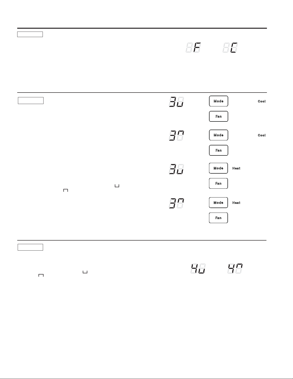
49-7774 7
Controles auxiliares del Zoneline
USO DEL ZONELINE
Fahrenheit / Celsius
Esta función le permite al individuo cambiar las unidades de
temperatura entre Fahrenheit y Celsius en la pantalla.
3UHVLRQH02'(0RGRKDVWDTXHDSDUH]FDXQHQHOSULPHUGtJLWR
de la pantalla para Fahrenheit/ Celsius en la pantalla.
Presione la tecla – para seleccionar Celsius o la tecla + para
seleccionar Fahrenheit. El individuo verá una F para Fahrenheit or
una C para Celsius en el segundo digito de la pantalla en base a la
selección.
/DFRQILJXUDFLyQSRURPLVLyQSDUDHO0RGRHVHQ)DKUHQKHLW
MODO 2
F
C
Ventilador Constante Encendido
3UHVLRQH02'(0RGRKDVWDTXHDSDUH]FDXQHQHOSULPHUGtJLWRGH
la pantalla para configurar el ventilador, a fin de que funcione de forma
continua en alta velocidad; incluso aunque la unidad esté apagada.
3UHVLRQHODWHFOD±SDUD2))$SDJDU³³RODWHFODSDUD21
(Encender) “ “. Esto se muestra en el segundo dígito de la pantalla.
Presione AUX SET (Configuración Auxiliar) para bloquear su selección
\VDOLGDGHOPRGR$8;6(7&RQILJXUDFLyQ$X[LOLDURSUHVLRQH02'(
(Modo) para continuar configurando otras funciones.
/DFRQILJXUDFLyQSRURPLVLyQSDUDHO0RGRHVWiHQ2))$SDJDGD
MODO 4
Centinela de Congelación/ Centinela
de Calefacción
Con la unidad encendida y Freeze Sentinel (Centinela de
Congelación) activado, la unidad brinda automáticamente calor
sin la interface de usuario. Esto evita posibles daños de plomería,
DOHQFHQGHUODFDOHIDFFLyQ\HOYHQWLODGRULQWHUQRHQ)\OXHJR
DSDJDUORXQDYH]TXHODWHPSHUDWXUDGHODPELHQWHDOFDQFHORV)
Cuando Heat Sentinel (Centinela de Calefacción) está activado, la
unidad brinda automáticamente frío sin la interface de usuario. Esto
evita que haya un calor excesivo en el ambiente, encendiendo el
acondicionador de aire en 85ºF y luego apagando el mismo una vez
TXHODWHPSHUDWXUDGHODPELHQWHDOFDQFHORV)
3UHVLRQH02'(0RGRKDVWDTXHDSDUH]FDXQHQHOSULPHU
dígito de la pantalla para el modo Freeze Sentinel (Centinela de
&RQJHODFLyQ/DOX]&22//('/('GH5HIUHVFDUGHOFRQWURO
SULQFLSDOHVWDUiHQFHQGLGR3UHVLRQH02'(0RGRQXHYDPHQWH
SDUDFDPELDUDO+HDW6HQWLQHO&HQWLQHODGH&DOHIDFFLyQ/DOX]
+($7/('/('GH&DOHIDFFLRQDUGHOFRQWUROSULQFLSDOHVWDUi
HQFHQGLGR3UHVLRQHODWHFOD±SDUD2))$SDJDU³³RODWHFOD
SDUD21(QFHQGHU³³(VWRVHPXHVWUDHQHOVHJXQGRGtJLWR
de la pantalla. Presione AUX SET (Configuración Auxiliar) para
bloquear su selección y salida del modo AUX SET (Configuración
$X[LOLDURSUHVLRQH02'(0RGRSDUDFRQWLQXDUFRQILJXUDQGR
otras funciones.
En la configuración por omisión para el Modo 3, el Heat Sentinel
(Centinela de Calefacción) está apagado, y el Freeze Sentinel
(Centinela de Congelación) está encendido.
NOTA: Estas funciones están activas cuando la unidad es
enchufada, incluso aunque la unidad esté apagada.
MODO 3
Centinela de
Congelación Apagado
Centinela de
Congelación
Encendido
Centinela de
Calefacción
Apagado
Centinela de
Calefacción
Encedido
Ventilador
Constante
Apagado
Ventilador
Constante
Encendido
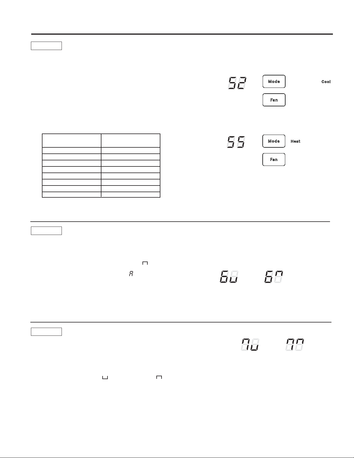
8 49-7774
Controles auxiliares del Zoneline
USO DEL ZONELINE
Modo de Conducto
Esta configuración es usada cuando la unidad es instalada
FRQXQNLWFRQDGDSWDGRUGHOFRQGXFWR6LODXQLGDGSRVHHXQ
FRQGXFWRVHGHEHUiFRQILJXUDU'XFW0RGH0RGRGH&RQGXFWR
HQ21(QFHQGHU(VWRLQFUHPHQWDODYHORFLGDGGHOYHQWLODGRU
asegurando una circulación adecuada.
3UHVLRQH02'(0RGRKDVWDTXHXQDSDUH]FDHQHOSULPHU
dígito de la pantalla. Presione la tecla + o - para configurar este
LQWHUUXSWRUHQ2))$SDJDGR³³X21(QFHQGLGR³³(VWR
se muestra en el segundo dígito de la pantalla. Presione AUX
SET (Configuración Auxiliar) para bloquear su selección y el
modo de salida AUX SET (Configuración Auxiliar).
3DUDHO0RGHOR$=SUHVLRQH02'(0RGRSDUDFRQWLQXDU
FRQILJXUDQGRRWUDVIXQFLRQHV3UHVLRQDU02'(0RGRHQHO
0RGHOR$=OHKDUiUHJUHVDUDOPRGR$8;6(7&RQILJXUDFLyQ
Auxiliar) y una “AU” aparecerá en la pantalla.
/DFRQILJXUDFLyQSRURPLVLyQSDUDHO0RGRHVWiHQ2))
(Apagada).
MODO 7
Limitación de Temperatura
/DOLPLWDFLyQGHWHPSHUDWXUDHVXQDIXQFLyQTXHUHGXFHORVFRVWRVGH
energía, limitando la temperatura más baja que se pueda obtener en
la refrigeración y la temperatura más alta que se pueda obtener en la
FDOHIDFFLyQ3UHVLRQH02'(0RGRKDVWDTXHDSDUH]FDXQHQHO
SULPHUGtJLWRGHODSDQWDOODSDUDSDUDHOPRGRIUtRGH7HPSHUDWXUH/LPLWLQJ
/LPLWDFLyQGH7HPSHUDWXUD/DOX]&22//('/('GH5HIUHVFDUGHO
control principal estará encendida. Para cambiar el modo de calefacción,
SUHVLRQH02'(0RGRQXHYDPHQWH\ODOX]+($7/('/('GH
Calefaccionar) del control principal se encenderá.
Para configurar los límites de temperatura, presione la tecla + o -. El
VHJXQGRGtJLWRGHODSDQWDOODVHUiHQWUH\GHSHQGLHQGRGHOOtPLWHTXH
desee configurar. El cuadro muestra los límites disponibles. Presione AUX
SET (Configuración Auxiliar) para bloquear su selección y salida del modo
$8;6(7&RQILJXUDFLyQ$X[LOLDURSUHVLRQH02'(0RGRSDUDFRQWLQXDU
configurando otras funciones.
/DFRQILJXUDFLyQSRURPLVLyQHVHQHO0RGR\HVODVLJXLHQWH
5HIUHVFDU)D)
&DOHIDFFLRQDU)D)
MODO 5
/tPLWHVGH7HPSHUDWXUD /tPLWHVGH7HPSHUDWXUD
Refrescar Calefaccionar
)WR) )WR)
)WR) )WR)
)WR) )WR)
)WR) )WR)
)WR) )WR)
)WR) )WR)
)WR) )WR)
)WR) )WR)
/LPLWDFLyQGH7HPSHUDWXUD)UHVFD±
/tPLWH
/LPLWDFLyQGH7HPSHUDWXUDGH&DOHIDFFLyQ±
/tPLWH
Use el Termostato de Pared
&RQILJXUDUHVWHPRGRHQ21(QFHQGLGRSHUPLWLUiTXHODXQLGDG
funcione con un Termostato de Pared a Control Remoto Clase 2.
3UHVLRQH02'(0RGRKDVWDTXHDSDUH]FDXQHQHOSULPHU
dígito de la pantalla para el modo Clase 2.
3UHVLRQHODWHFODSDUDDFWLYDUODRSFLyQ21³
” para
termostatos de “frío/calor estándar”. Presione la tecla +
QXHYDPHQWHSDUDDFWLYDUODRSFLyQ21³
“ para el
termostato de “cambio automático”. Puede presionar la tecla
– para regresar a la configuración anterior. Pre
ss AUX SET
WRORFNLQ\RXUVHOHFWLRQDQGH[LWAUXAppuyez sur AUX
Presione AUX SET (Configuración Auxiliar) para bloquear su
selección y salida del modo AUX SET (Configuración Auxiliar),
RSUHVLRQH02'(0RGRSDUDFRQWLQXDUFRQILJXUDQGRRWUDV
funciones.
/DFRQILJXUDFLyQSRURPLVLyQSDUDHO0RGRHVWiHQ2))
(Apagada). Cuando este modo esté activado, la pantalla
mostrará “Usar Termostato de Pared” cuando cualquier tecla sea
presionada.
MODO 6
Clase 2
Apagado
Clase 2
Encendido
Modo de
Conducto
Apagado
Modo de
Conducto
Encendido
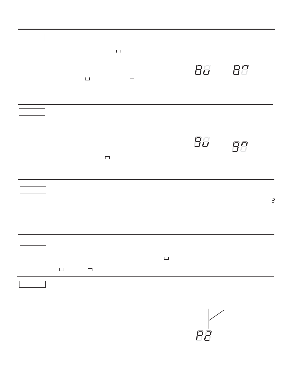
49-7774 9
Controles auxiliares del Zoneline
USO DEL ZONELINE
Esta opción de calefacción eléctrica funciona sólo con el modelo
$=&XDQGRHVWDRSFLyQHVWiHQ21(QFHQGLGD³³HO
funcionamiento de la bomba de calor está bloqueado, haciendo que
la unidad sólo brinde calefacción de resistencia eléctrica.
Para configurar la opción All-Electric Heat (Calefacción Sólo
(OpFWULFDSUHVLRQH02'(0RGRKDVWDTXHXQDSDUH]FDHQHO
primer dígito de la pantalla. Presione la tecla + o - para configurar
HVWHLQWHUUXSWRUHQ2))$SDJDGR³³X21(QFHQGLGR³³
Esto se muestra en el segundo dígito de la pantalla.
Presione AUX SET (Configuración Auxiliar) para bloquear su
selección y salida del modo AUX SET (Configuración Auxiliar),
RSUHVLRQH02'(0RGRSDUDFRQWLQXDUFRQILJXUDQGRRWUDV
funciones.
/DFRQILJXUDFLyQSRURPLVLyQSDUDHO0RGRHVWiHQ2))
(Apagada).
&XDQGR+HDW%RRVW$FHOHUDU&DOHIDFFLyQHVWiHQ21
(QFHQGLGR\ODVWHPSHUDWXUDVH[WHUQDVVRQGHHQWUH)
\)EULQGDFDOHIDFFLyQHOpFWULFDFRPSOHPHQWDULDDO
funcionamiento de la bomba de calor para ayudar a mantener
una temperatura ambiente consistente y confortable.
3DUDFRQILJXUDU+HDW%RRVW$FHOHUDU&DOHIDFFLyQSUHVLRQH
02'(0RGRKDVWDTXHXQDSDUH]FDHQHOSULPHUGtJLWRGHOD
pantalla. Presione la tecla + o - para configurar este interruptor
HQ2))$SDJDGR³³X21(QFHQGLGR³³(VWRVH
muestra en el segundo dígito de la pantalla. Presione AUX SET
(Configuración Auxiliar) para bloquear su selección y el modo de
salida AUX SET (Configuración Auxiliar).
/DFRQILJXUDFLyQSRURPLVLyQSDUDHO0RGRHVWiHQ2))
(Apagada).
Calefacción Sólo Eléctrica (AZ65 únicamente)
MODO 8
Acelerar Calefacción (AZ65 únicamente)
MODO 9
Calefacción
Sólo Eléctrica
Apagada
Calefacción
Sólo
Eléctrica
Encendida
Aceleración de
Calefacción
Apagada
Aceleración de
Calefacción
Encedida
MODE 0
Velocidad del Ventilador del Módulo de Aire de Reposición Digital
3UHVLRQHODWHFOD02'(0RGRKDVWDTXHDSDUH]FDHOHQHO
SULPHUGtJLWRGHODSDQWDOODSDUDDFWLYDUHOPRGR'LJLWDO0DNHXS
$LU$LUHGH5HSRVLFLyQ'LJLWDO3DUDDSDJDUHOPRGXORRFDPELDU
ODVYHORFLGDGHVGHOYHQWLODGRUSUHVLRQHODVWHFODVR
LQGLFDTXHHOPRGXORHVWiDSDJDGR PyGXORDFWLYDGRFRQ
YHQWLODGRUHVFRQILJXUDGRVDFIP PyGXORDFWLYDGRFRQ
YHQWLODGRUHVFRQILJXUDGRVDFIPHWF
/DFRQILJXUDFLyQSRURPLVLyQSDUDHOPyGXORHVWiHQ21³
“ con el ventilador en una velocidad de 35 cfm.
MODE E
Ocupación del Módulo de Aire de Reposición Digital
Para activar la detección de la ocupación, presione la tecla
02'(0RGRKDVWDTXHDSDUH]FDXQD(HQHOSULPHUGtJLWRGHOD
pantalla. Presione la tecla + o – para configurar la detección de la
RFXSDFLyQHQ2))³
´RHQ21³ ”.
/DFRQILJXUDFLyQSRURPLVLyQSDUDHO0RGR(HVWiHQ
2))³
”.
MODE P
Configuración de la Revisión de Ingeniería
Esta configuración es utilizada para configurar la unidad cuando el
tablero del circuito sea reemplazado.
Cuando la unidad sea encendida por primera vez luego de la
instalación del tablero de servicios, la unidad ingresará de forma
DXWRPiWLFDDHVWHPRGR(QHO8,VHOHHUi³3´3UHVLRQHODWHFOD
“+” hasta que el número coincida con la revisión de ingeniería,
FRPRVHPXHVWUD/DUHYLVLyQGHLQJHQLHUtDHVHO~OWLPRQ~PHUR
del número de modelo. Presione “Aux” para guardar y salir.
/DUHYLVLyQGHLQJHQLHUtDSRGUiVHUDMXVWDGDOXHJRGHOSULPHU
ciclo de energía donde se use AUX SET (Config. Aux.). Presione
02'(0RGRKDVWDTXHDSDUH]FD³3´HQHOSULPHUGtJLWR\VLJD
los pasos descriptos más arriba.
Ejemplo de Nomenclatura
AZ45E09DABW2
Revisión de Ingeniería
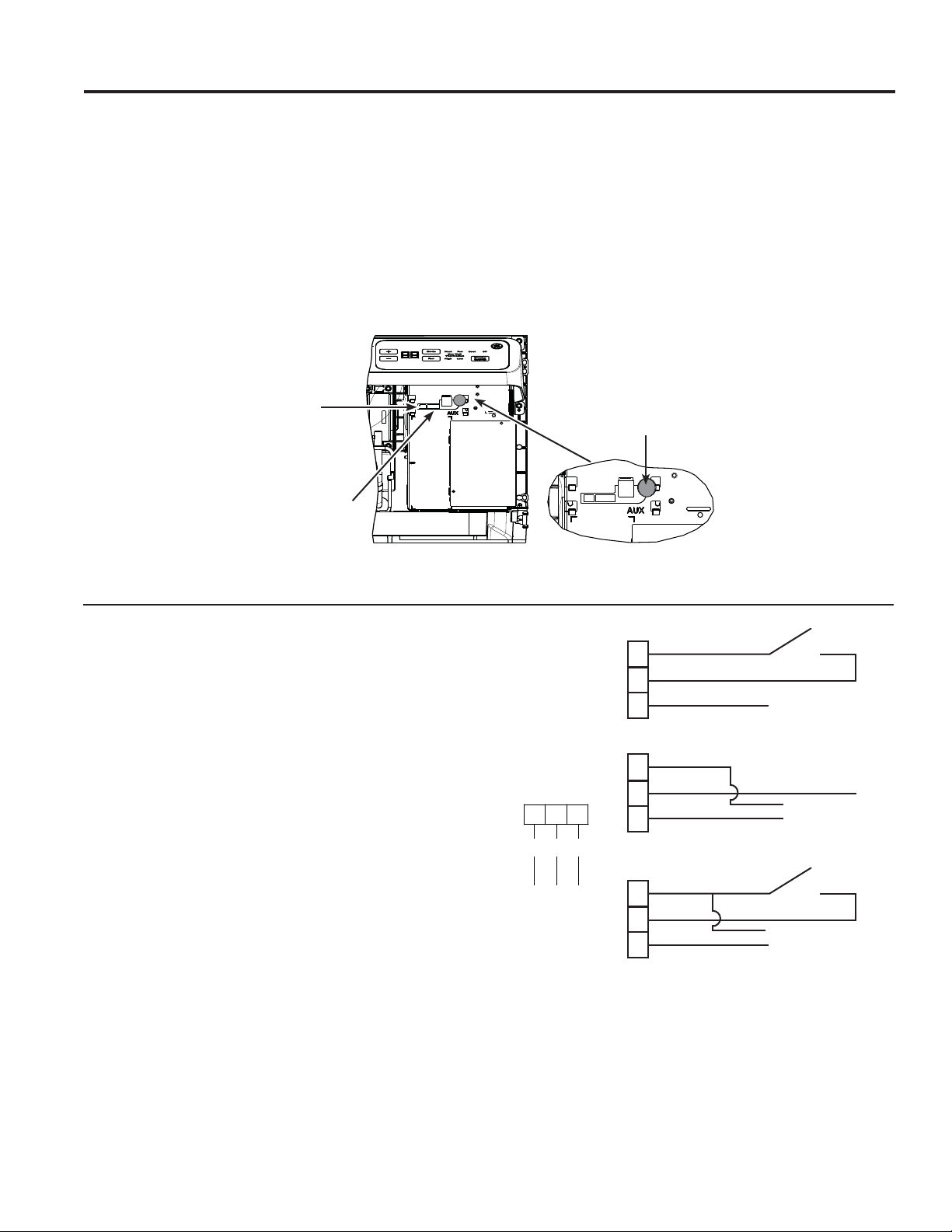
49-7774
Controles auxiliares del Zoneline
USO DEL ZONELINE
Ventilador Externo (Instalados en Campo)
Cuando esté conectado, un ventilador auxiliar o externo puede ser
FRQWURODGRFRQHOPRWRUGHOYHQWLODGRULQWHUQRGHO=RQHOLQH/DV
FRQH[LRQHVEULQGDQ9$&SDUDDOLPHQWDUXQUHOpUHPRWR
(ODFFHVRULR5$.&'&GHEHUiVHUXWLOL]DGRFXDQGRVHXVHXQ
ventilador externo.
Control desde la Mesa Central (Suministrado en Campo)
&HQWUDO'HVN&RQWURO&RQWUROGHVGHOD0HVD&HQWUDOHVXQD
función que permite que la unidad sea operable/ inoperable desde
una ubicación remota. El funcionamiento de la función requiere
TXHXQLQWHUUXSWRU212))HQFHQGLGRDSDJDGRHQODXELFDFLyQ
UHPRWDHVWpFRQHFWDGRSRUFDEOHDODVGRVWHUPLQDOHVGHOD&'&
HQHOSDQHOGHFRQWUROGHO=RQHOLQH&XDQGRHOLQWHUUXSWRUUHPRWR
HVWpHQ&/26('&HUUDGRODXQLGDGQRSRGUiVHURSHUDGD
desde el control en los modos Fan (Ventilador), Cool (Refrescar), o
+HDW&DOHIDFFLRQDU/DVIXQFLRQHVGH)UHH]H6HQWLQHO&HQWLQHOD
de Congelación) y Heat Sentinel (Centinela de Calefacción)
permanecen operables. Cuando el interruptor remoto está en
2SHQ$ELHUWRODXQLGDGSXHGHVHURSHUDGDFRPSOHWDPHQWH
desde el control.
'HEHVHUREVHUYDGRTXH&'&QRSXHGHVHUXVDGRHQORV
PRGHORV'%0\(%0FXDQGRODRFXSDFLyQHVWpDFWLYDGD
12
3
R
CDC
Ext Fan
RedCDC
Ext Fan
&'&6ZLWFK
&'&6ZLWFK
&'&
&'&
&'&
R
R
R
E. Fan
E. Fan
E. Fan
Connect to exter-
nal fan relay
Connect to external
fan relay
Controles Auxiliares – Conexiones de la Terminal
/DVILFKDVGHFRQH[LyQGHODWHUPLQDOGHFRQWURODX[LOLDUHVWiQ
ubicadas detrás de la tapa del acondicionador de aire de pared,
debajo de la tapa de acceso.
1. Apague y desenchufe la unidad.
2. Retire la tapa del acondicionador de aire de pared. Consulte
la sección Para Retirar la Tapa del Acondicionador de Aire de
Pared.
3. Para realizar conexiones de cables, inserte los conectores en
las terminales correspondientes de la caja de control.
4. Una vez realizadas todas las conexiones deseadas,
reemplace la tapa de acceso y la tapa del acondicionador de
aire de pared.
El propietario es responsable de realizar todas las conexiones
y de configurar el modo AUX SET (Configuración Auxiliar)
adecuado.
AVISO:
Un cableado incorrecto podrá dañar las piezas electrónicas del
=RQHOLQH1RVHSHUPLWHXQWUDQVSRUWHFRP~Q6HSRGUiQSURGXFLU
daños o un funcionamiento errático. Un par de cables aparte se
deberán instalar desde cada interruptor de control separado hasta
FDGD=RQHOLQHLQGLYLGXDO
%RWyQGH
Configuración
Auxiliar Rojo
Ventilador Externo/
)LFKDGHO&RQHFWRU&'&
Ficha del Conector del
Termostato Remoto
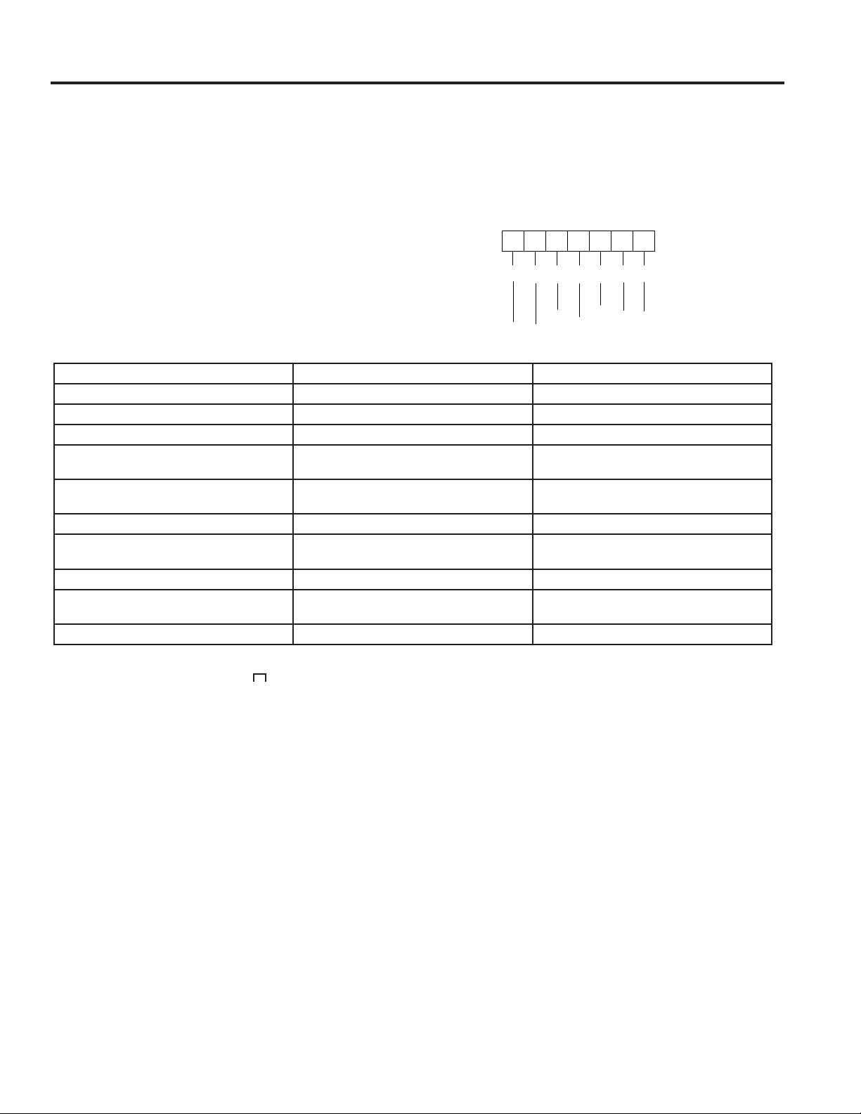
49-7774
USO DEL ZONELINE
Termostato Remoto
/RV&RQHFWRUHVGHO7HUPRVWDWR5HPRWRHVWiQLQFOXLGRVFRQFDGD
=RQHOLQH
Cuando se conecte a un termostato remoto, el sensor de temperatura
de aire interno se pasa desde la unidad al termostato remoto. Por esta
razón, las unidades funcionarán de forma levemente diferente cuando
se conecten a un termostato remoto. El siguiente cuadro muestra el
funcionamiento de la unidad cuando está conectada a un termostato
remoto.
IMPORTANTE: /DVFRQH[LRQHVGHOWHUPRVWDWRGHO
=RQHOLQHEULQGDQ9$&~QLFDPHQWH
Si usará un termostato de pared digital/ electrónico, deberá configurarlo
HQHODMXVWHGH9$&&RQVXOWHODV,QVWUXFFLRQHVGH,QVWDODFLyQSDUD
el termostato de pared.
AVISO:
'DxRVVREUHXQWHUPRVWDWRGHSDUHGRODVSLH]DVHOHFWUyQLFDVGHO
=RQHOLQHSXHGHQSURYRFDUFRQH[LRQHVLQDGHFXDGDV6HGHEHUi
tener especial cuidado al conectar los cables. No se deberán
realizar conexiones de la línea de voltaje en ningún circuito. Aisle
todos los cables del edificio de la línea de voltaje.
NOTA: /DFRQILJXUDFLyQGHO0RGRGH&ODVH0RGRGHEH
VHUFRQILJXUDGRHQ21(QFHQGLGR³³SDUDTXHODXQLGDG
funcione con un Termostato de Pared Remoto Clase 2. (Consulte
las Instrucciones de Instalación suministradas con el termostato
UHPRWR\ODVLQVWUXFFLRQHVGHOPRGRHQODSiJLQD
Función Bomba de Calor Calefacción Eléctrica
Control de Congelación Interna Sí Sí
Centinela de Congelación Sí Sí
/LPLWDFLyQGH7HPSHUDWXUD(OHFWUyQLFD No No
Interruptor del Calor de la Resistencia
%DVDGDHQOD7HPSHUDWXUD,QWHUQD
'HWHUPLQDGRSRUHO7HUPRVWDWR5HPRWR N/A
Interruptor del Calor de la Resistencia
%DVDGDHQOD7HPSHUDWXUD([WHUQD
Sí N/A
'HVFRQJHODFLyQSRU&LFORGH,QYHUVLyQ Sí N/A
Calor Parcial de la Resistencia en Si-
PXOWiQHRFRQOD%RPEDGH&DORU
Sí N/A
%ORTXHRGHO&DORUGHOD5HVLVWHQFLD Sí N/A
Ciclo de Ventilación del “Ventilador
Inteligente”
9HQWLODGRU(1&(1','2$8720È7,&2
Configurado en Termostato Remoto
Ventilador Encendido/Automático Con-
figurado en Termostato Remoto
&HQWUDO'HVN&RQWURO Sí Sí
Controles auxiliares del Zoneline
123456
7
C
W
YB
GH
GL
R
yellow
black
white
blue
green
tan
red
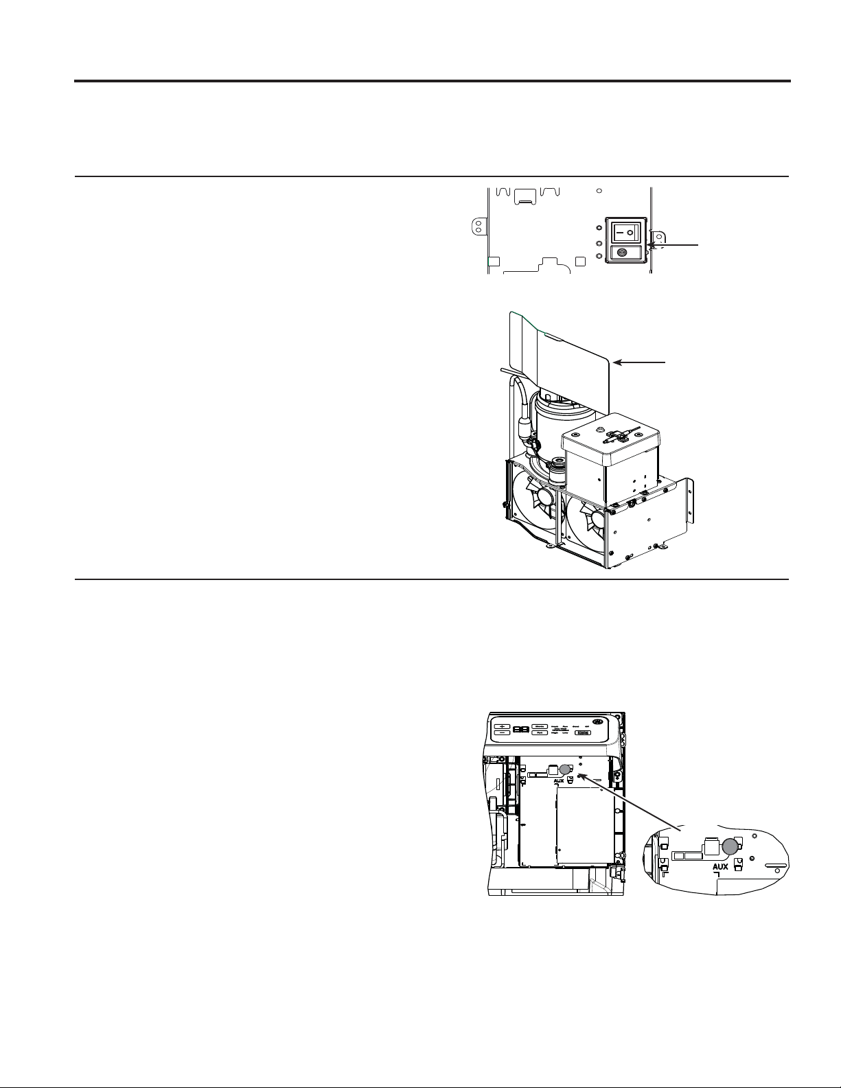
49-7774
USO DEL ZONELINE
Modelos con Aire de Reposición (no en todas las unidades)
El sistema de ventilación con aire de reposición fue
diseñado para brindar aire externo de forma continua, a
través de la puerta de ventilación y en la sala. Además
de brindar aire fresco, deshumidifica el aire entrante
cuando la humedad relativa es superior al 55%.
El sistema de ventilación de aire de reposición es
operado a través de una palanca ubicada en la parte
frontal de la tapa del control eléctrico, debajo del
IUHQWHGHOHVSDFLRGHO=RQHOLQH(OVLVWHPDHVDFWLYDGR
y desactivado pulsando el botón de encendido (I)
RHOERWyQGHDSDJDGR2FRPRVHPXHVWUDHQOD
ilustración.
6LHO=RQHOLQHGHEHVHURSHUDGRFRPR37$&R37+3
únicamente, se deberán seguir los siguientes pasos:
2UGHQHODSLH]DGHVHUYLFLR1:3;
'HVHQFKXIHHO=RQHOLQH
3. Retire el frente del espacio.
$SDJXHHOVLVWHPDGHYHQWLODFLyQSUHVLRQDQGRHO
botón on/off (encendido/ apagado), de modo que off
DSDJDGR2VHDVHOHFFLRQDGRFRQVXOWHODXELFDFLyQ
en la ilustración que aparece más arriba).
(PSXMHKDFLDXVWHGHO=RQHOLQHDWUDYpVGHOD
manga de la pared e instale la pieza de servicio Nº
:3;FRPRVHPXHVWUDHQODLOXVWUDFLyQ
9XHOYDDHPSXMDUHO=RQHOLQHVREUHODPDQJDGHOD
pared y vuelva a activar la corriente en la unidad.
*Modelos DAM
Service PN
:3;
2Q2II
El sistema de ventilación de aire de reposición es operado
DWUDYpVGHOPHQ~DX[LOLDUGHO=RQHOLQHFRQVXOWHODVHFFLyQ
de Controles Auxiliares). Para encender o apagar el
sistema, siga las siguientes instrucciones:
5HWLUHHOIUHQWHGHOHVSDFLR
2. Presione el botón de control de modo y apague la
unidad.
3. Presione el botón AUX SET (Config. Aux., “AU” es
visualizado en la pantalla).
3DUDDSDJDUHO08$0SUHVLRQHHOERWyQGHFRQWUROGH
PRGRKDVWDTXHVHYLVXDOLFH³´HQHOSULPHUGtJLWR
5. Presione la tecla menos en el panel de control, hasta
TXHVHYLVXDOLFH³´SDUDDSDJDUHOPyGXORGHDLUHGH
reposición.
6. El sistema está preconfigurado de fábrica en 35 cfm.
Para modificar dicho valor, presione las teclas + o –
hasta alcanzar la velocidad del ventilador deseada:
FIP FIP FIP FIP FIP\
FIP
7. Pulse el botón auxiliar rojo nuevamente para regresar al
funcionamiento normal.
6LHO=RQHOLQHGHEHVHURSHUDGRFRPR37$&R37+3
únicamente, se deberán seguir los siguientes pasos:
2UGHQHODSLH]DGHVHUYLFLR1:3;
'HVHQFKXIHHO=RQHOLQH
3. Retire el frente del espacio.
$SDJXHHOPyGXORGHODSLH]DGHDLUHGHUHSRVLFLyQ
como se indica más arriba
(PSXMHKDFLDXVWHGHO=RQHOLQHDWUDYpVGHODPDQJDGH
ODSDUHGHLQVWDOHODSLH]DGHVHUYLFLR1:3;
como se muestra en la ilustración.
9XHOYDDHPSXMDUHO=RQHOLQHVREUHODPDQJDGHOD
pared y vuelva a activar la corriente en la unidad.
NOTA: /DVXQLGDGGHDLUHGHUHSRVLFLyQGLJLWDOUHDOL]DUiQ
un control del sistema sobre el encendido, sobre el ciclo de
corriente, y una vez cada 7 días si la unidad se encuentra
en el modo de ocupación. El control del sistema dura
DSUR[LPDGDPHQWHVHJXQGRV'XUDQWHHVWHWLHPSRORV
ventiladores se acelerarán, reducirán su velocidad, y luego
irán al punto de configuración.
*Modelos *DBM y *EBM
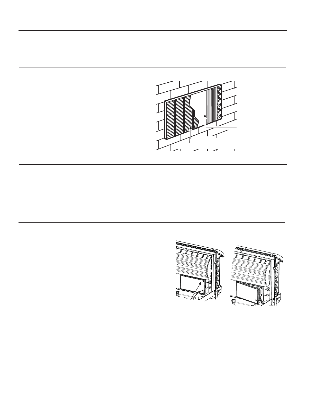
49-7774
Cuidado y Limpieza
La Bandeja de la Base
En algunas instalaciones, la tierra u otros desechos podrán
ingresar a la unidad desde el exterior y asentarse en la bandeja
de la base (la parte inferior de la unidad).
En algunas zonas de Estados Unidos, como naturalmente
sucede, se podrá visualizar una sustancia “similar al gel” o “similar
a la baba” en la bandeja de la base.
Controle la misma de forma periódica y límpiela si es necesario.
(QORVPRGHORVGHOD6HULHQRUHWLUHHOFDEOHGHJRPD
GHOGUHQDMHTXHVHHQFXHQWUDHQODEDQGHMDGHODEDVH'HVHU
retirado, se podrá drenar el exceso de agua hacia el exterior.
Bobinas Externas
/DVERELQDVGHOODGRH[WHUQRGHO=RQHOLQHVHGHEHUiQFRQWURODU
de forma regular. Si están atascadas con tierra u hollín, deberán
ser limpiadas a través de métodos con poca o sin presión.
Asegúrese de que el área/ dispositivos eléctricos estén protegidos
GXUDQWHODOLPSLH]D'HEHUiUHWLUDUODXQLGDGGHODPDQJDGHOD
SDUHGSDUDLQVSHFFLRQDUODVERELQDV/DDFXPXODFLyQGHVXFLHGDG
se produce del lado donde se encuentra el ventilador en la bobina
externa.
/LPSLHODVERELQDVH[WHUQDVGHIRUPDUHJXODU
Tapa y Caja del Acondicionador de Aire de Pared
$SDJXHHO=RQHOLQH\GHVFRQHFWHHOVXPLQLVWURGHFRUULHQWH Para limpiar, use agua y un detergente suave. No use
blanqueadores ni abrasivos. Algunos limpiadores comerciales
pueden dañar las partes plásticas.
%RELQDV
Rejilla
Filtro de la Ventilación
Si la puerta de la ventilación está abierta, limpie el filtro de la
ventilación dos veces al año o cuando sea necesario. El acceso
requiere el retiro de la unidad de la manga de la pared.
Apague el Zoneline y desenchufe el mismo antes de su retiro y
limpieza.
Para limpiar el filtro de ventilación:
IMPORTANTE: El filtro no puede ser retirado.
Intentar retirar este filtro dañará la unidad.
Ŷ8VHXQDDVSLUDGRUDSDUDHOLPLQDUORVGHVHFKRVGHOILOWUR
Ŷ8VHXQWUDSRK~PHGRSDUDOLPSLDUHOILOWUR\HOiUHDFLUFXQGDQWH
luego de usar la aspiradora.
Retire los
tornillos
enviados (si
se desea esta
operación)
CUIDADO Y LIMPIEZA
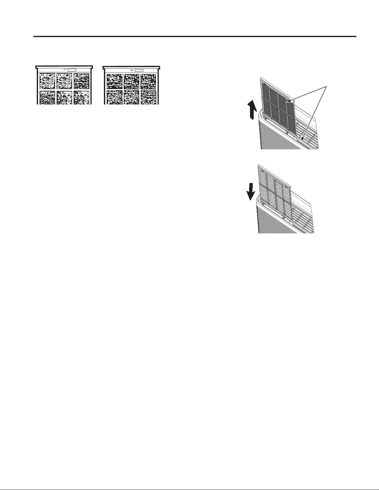
49-7774
Cuidado y Limpieza
CUIDADO Y LIMPIEZA
Para mantener un rendimiento óptimo, limpie los filtros por lo menos cada 30 días.
Filtros de Aire
FRONT
FRONT
Filtro sucio – Debe ser
limpiado
Filtro atascado – Gran
reducción de la refrigeración,
calefacción y flujo de aire.
Apague el Zoneline antes de limpiarlo.
/RPiVLPSRUWDQWHTXHSXHGHKDFHUSDUDPDQWHQHUHO=RQHOLQHHQ
EXHQDVFRQGLFLRQHVHVOLPSLDUHOILOWURSRUORPHQRVFDGDGtDV
/RVILOWURVDWDVFDGRVUHGXFHQODUHIULJHUDFLyQFDOHIDFFLyQ\IOXMR
de aire.
Mantener estos filtros limpios hará que:
Ŷ6HUHGX]FDHOFRVWRGHOIXQFLRQDPLHQWR
Ŷ6HDKRUUHHQHUJtD
Ŷ6HSUHYHQJDHODWDVFDPLHQWRGHODVERELQDVLQWHUFDPELDEOHVGH
calefacción.
Ŷ6HUHGX]FDHOULHVJRGHIDOODVSUHPDWXUDVGHORVFRPSRQHQWHV
Para limpiar los filtros de aire:
Ŷ$VSLUHODVXFLHGDGSHVDGD
Ŷ'HMHFRUUHUDJXDDWUDYpVGHORVILOWURVGHVGHODSDUWHWUDVHUD
Ŷ6HTXHWRWDOPHQWHDQWHVGHOUHHPSOD]R
NOTA: /RVILOWURVGHDLUHVRQLQWHUFDPELDEOHV\HQFDMDUiQWDQWR
del lado derecho como del izquierdo.
Para retirar los filtros de aire:
Para reemplazar los filtros de aire:
AVISO:
1RXWLOLFHHO=RQHOLQHVLORVILOWURVQRHVWiQHQVXVSRVLFLRQHV
correspondientes. Si un filtro se rasga o daña, deberá ser
reemplazado de inmediato.
Realizar el uso sin los filtros en sus posiciones correspondientes
o con daños permitirá que la tierra o el polvo lleguen a la bobina
interna y reduzcan el nivel de refrigeración, calefacción, flujo y de
aire y eficiencia de la unidad.
Filtros de reemplazo están disponibles a través de su vendedor,
minorista de GE Appliances, GE Appliances Service and Parts
Center (Centro de Servicio y Piezas de GE Appliances) o de
proveedores del servicio de Customer Care®.
Empuje hacia
arriba
Empuje hacia
abajo
2 filtros de
aire
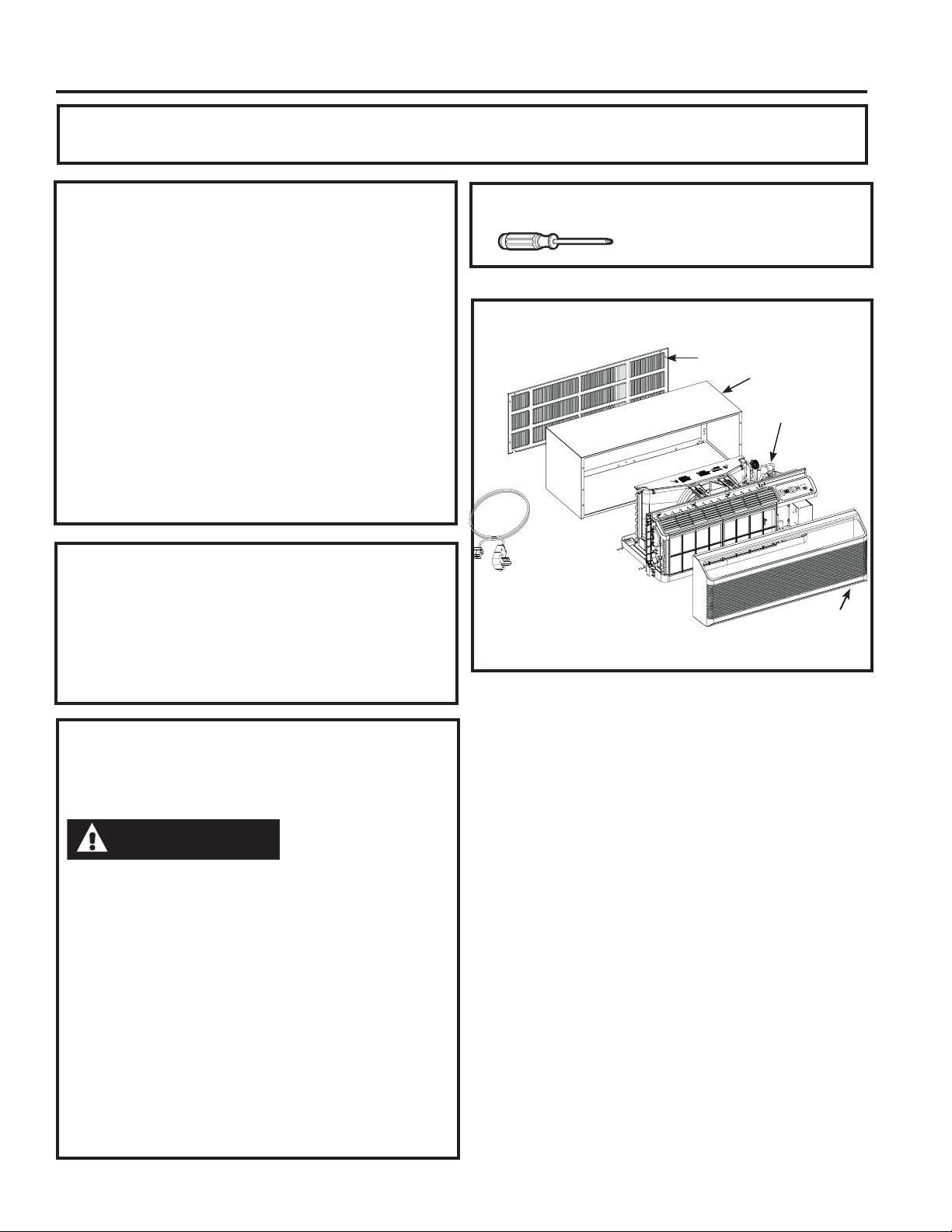
49-7774
Instrucciones de Instalación
INSTRUCCIONES DE INSTALACIÓN
ANTES DE COMENZAR
Lea estas instrucciones en su totalidad y atentamente.
•
IMPORTANTE – Conserve estas
instrucciones para uso del inspector local.
•
IMPORTANTE – Cumpla con todos
los códigos y ordenanzas gubernamentales. .
• Nota para el Instalador – Asegúrese de
que el propietario conserve estas instrucciones.
• Nota para el Propietario – Conserve
estas instrucciones para referencia futura.
• /DFRUUHFWDLQVWDODFLyQGHOSURGXFWRHV
responsabilidad del instalador.
• Si se producen fallas en el producto debido a una
instalación inadecuada, la Garantía no cubrirá las
mismas.
¿Preguntas? Llame al 844-GE4-PTAC (o al 844-434-7822 ) o Visite nuestro sitio Web en:
GEAppliances.com
SEGURIDAD ELÉCTRICA
IMPORTANTE - LEA
ATENTAMENTE
• Siga las instrucciones del National Electrical Code (Código
de Electricidad Nacional) (NEC) o los códigos u ordenanzas
locales.
•Para su seguridad personal, el acondicionador de aire Zoneline
debe tener una adecuada conexión a tierra.
• Los dispositivos de protección (fusibles o disyuntores)
adecuados para las instalaciones de Zoneline se encuentran
especificados en la placa de cada unidad.
• No utilice un cable de extensión con esta unidad.
• El cableado de aluminio puede presentar problemas especia-
les: consulte a un electricista calificado.
• Cuando la unidad se encuentra en la posición OFF (apagado),
todavía hay voltaje en los controles eléctricos.
• Antes de realizar reparaciones en la unidad, desconecte el
suministro de energía de la siguiente manera:
1
Retire el cable eléctrico (si posee uno) del receptáculo de la
pared. O
2
Retire los fusibles de la sección o apague el disyuntor desde
el panel.
'HVWRUQLOODGRU3KLOOLSV\OODYHGH
WXHUFDVGH´
HERRAMIENTAS NECESARIAS
NOTA – Al igual que con cualquier dispositivo mecánico
con partes móviles, esta unidad pasará por un período de
DFRVWXPEUDPLHQWR/8(*2'(/$,167$/$&,Ï1HVWD
XQLGDGGHEHUiVHUXVDGDGXUDQWHKRUDVSDUDORJUDUHO
nivel de eficiencia máximo.
PERÍODO DE PRUEBA
DEUNCIONAMIENTO DEL
ACONDICIONADOR DE AIRE
COMPONENTES DEL ZONELINE
El aspecto puede variar.
(QYLDGRFRQODXQLGDGGHO=RQHOLQH
** Controle la lista de “Elementos
Esenciales” en la unidad ubicada
en el frente de la bandeja de la
base.
Rejilla Externa/ Montaje**
Caja de pared**
Unidad del
=RQHOLQH
Tapa del
acondicionador
de aire de pared**
Kit de
suministro de
corriente**
PRECAUCIÓN
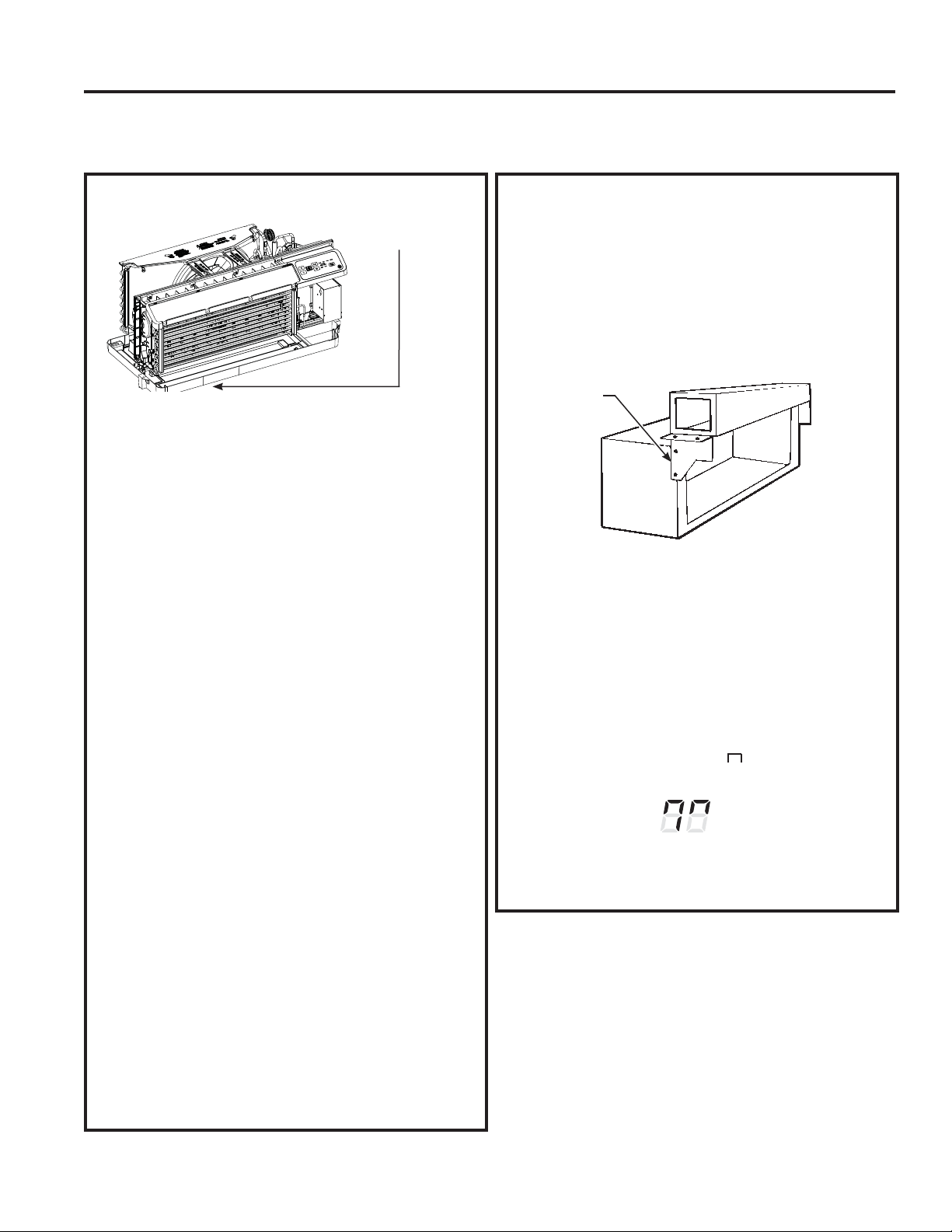
49-7774
Instrucciones de Instalación
INSTRUCCIONES DE INSTALACIÓN
Use la caja de pared correcta
Esta unidad fue diseñada para ser instalada en
la caja de la pared metálica de plástico o aislada
de GE Appliances. Esto minimiza la formación de
condensación del lado de la caja del acondicionador
de aire de pared.
NOTA: Existen varios agujeros adicionales en las
lengüetas laterales de la unidad para la instalación en
otras cajas de pared que no sean de GE Appliances.
A fin de evitar daños en la aislación de la pestaña, el
instalador deberá usar un punzón u otra herramienta
puntiaguda para perforar la aislación en los agujeros
apropiados antes de instalar los tornillos de adhesión.
Use la rejilla externa adecuada
'HEHUiXVDUODVUHMLOODVH[WHUQDVPRVWUDGDVHQOD
etiqueta de “Elementos Esenciales” de la bandeja
de la base.
• Si una rejilla existente no es reemplazada, la
capacidad y eficiencia se verán reducidas y la unidad
podrá no funcionar de forma adecuada o fallar de
IRUPDSUHPDWXUD8QNLWGHOGHIOHFWRU5$.SRGUi
ser usado con rejillas que no fueron diseñadas para
VXQXHYR=RQHOLQHGH*($SSOLDQFHV(O5$.
contiene deflectores de aire y juntas que se montan
a la unidad para alejar la salida del aire caliente de
la entrada de aire, y permitir que la unidad funcione
correctamente. La rejilla debe contar con un área
libre mínima de un 65 % (según lo calculado
por ASHRAE). Para acceder a información
PiVGHWDOODGDFRQVXOWHHO0DQXDOGH'DWRVGH
Arquitectos e Ingenieros (Architects and Engineers
'DWD0DQXDO
• Cualquier deflector vertical de una rejilla trasera
existente de GE deberá ser retirada a fin de reducir
la recirculación de aire del condensador que puede
hacer que la unidad realice un “ciclo corto” y conducir
a fallas prematuras de los componentes.
Use el cable de corriente adecuado
/RVFyGLJRVORFDOHVSXHGHQUHTXHULUHOXVRGH
dispositivos de fallas de arco o de detección de
SpUGLGDVGHFRUULHQWHHQLQVWDODFLRQHVGH
voltios.
Reemplazo de una unidad con conducto
Nueva instalación con conducto: Si esta unidad
será instalada en una nueva aplicación con conducto
XWLOL]DQGRXQNLWGHDGDSWDGRUGHFRQGXFWRHONLW
deberá ser instalado antes de que la unidad sea
ubicada en una caja de pared. Siga las instrucciones
GHLQVWDODFLyQLQFOXLGDVFRQHONLW
Kits de conductos disponibles:
5$.
5$.%%
Instalación con conducto existente:
El reemplazo de una unidad con conducto existente
podrá requerir diferentes componentes. Solicite esta
información a su representante de ventas. Los sellos
del conducto en la unidad existente deben ser
retirados y agregados a la nueva unidad.
• Reemplazo de las unidades de 230/208 voltios:
&RQVXOWHODSiJLQD
• Reemplazo de las unidades de 265 voltios:
&RQVXOWHODSiJLQD
Al usar un kit del conducto, siempre se debe usar
el Modo 7 en ON (Encender) “ “. Consulte las
LQVWUXFFLRQHVGH0RGRHQODSiJLQD
REEMPLAZO DE LA UNIDAD EXISTENTE
Controle la etiqueta de
“Elementos Esenciales”
para acceder a
información importante.
Conducto
Caja
Placa de
Montaje
Modo de Conducto
0RVWUDGRHQ21
(Encendido)
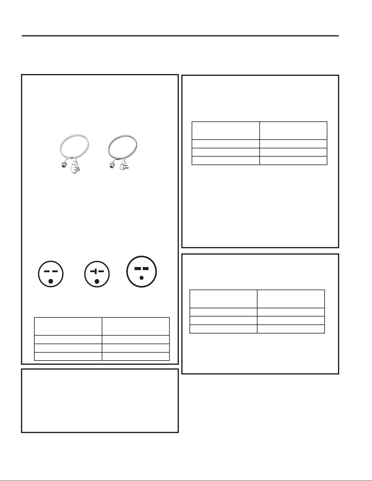
49-7774
Instrucciones de Instalación
INSTRUCCIONES DE INSTALACIÓN
CONEXIÓN ELÉCTRICA DE
SUB-BASE
Los cables de corriente pueden incluir un dispositivo
de interrupción de fallas de arco o de detección
de pérdidas de corriente. Se brinda un botón de
evaluación y reinicio en la caja del enchufe o en la
caja en línea. El dispositivo deberá ser evaluado de
forma periódica, presionando primero el botón TEST
(Evaluar) y luego RESET (Reinicio). Si el botón TEST
(Evaluar) no se activa o el botón RESET (Reinicio) no
permanece en su posición, deje de usar el Zoneline y
comuníquese con un técnico calificado del servicio.
'HSHQGLHQGRGHODDSOLFDFLyQXQNLWGHVXPLQLVWURGHFRUULHQWH
FRQ/&',GHEHUiVHUXVDGRSDUDVXPLQLVWUDUFRUULHQWHDOD
XQLGDGGHO=RQHOLQH(ONLWDSURSLDGRHVGHWHUPLQDGRSRUHO
voltaje, los medios de conexión eléctrica y el amperaje del
circuito de empalmes.
/DVFRQH[LRQHVGHORVFLUFXLWRVGHRYROWLRV
SXHGHQHVWDUFRQXQNLWGHVXPLQLVWURGHFRUULHQWHRXQNLW
de caja de empalmes.
Todo el cableado, incluyendo la instalación del
receptáculo, deberá cumplir con el NEC y los códigos,
RUGHQDQ]DV\UHJODPHQWDFLRQHVORFDOHV/RVFyGLJRV
requieren el uso de un dispositivo de detección de fallas
de arco o pérdidas de corriente en el cable de corriente,
excepto en contacto directo. Asegúrese de seleccionar el
cable correcto para su instalación.
OPCIONES DE CONEXIÓN ELÉCTRICA
DE 230/208 VOLTIOS
CONEXIÓN DEL CABLE DE
CORRIENTE
CONEXIÓN DIRECTA
2UGHQHHOVLJXLHQWH.LWSDUDODFRQH[LyQGLUHFWDGH
YROWLRVVHJ~QORUHTXHULGR
Revise las instrucciones de instalación provistas con el
FDEOHGHFRUULHQWHRFRQORVNLWVGHFRQH[LyQGLUHFWDSDUD
acceder a instrucciones detalladas sobre el ensamble.
Si usará una conexión de sub-base, la Caja de Empalmes
5$.&WDPELpQHVQHFHVDULDSDUDXQDLQVWDODFLyQ
completa.
Tándem
DPSHUHV
&RQILJXUDFLyQGHOUHFHSWiFXORGHYROWLRV
Perpendicular
DPSHUHV
Tándem
Grande
DPSHUHV
Kit de suministro de corriente
(El aspecto puede variar)
/RVPRGHORVSRGUiQVHULQVWDODGRVXVDQGRXQD
de las siguientes sub-bases eléctricas:
/DVVXEEDVHVHOpFWULFDVEULQGDQXQFHUUDPLHQWRSDUD
ODFRQH[LyQGLUHFWDRUHFHSWiFXORVFHUUDGRV(ONLWGH
sub-base incluye el cable de corriente.
/DVLQVWUXFFLRQHVSURYLVWDVFRQHONLWGHVXEEDVH
seleccionado se deben seguir de forma cuidadosa. Es
responsabilidad del instalador asegurar que la conexión
de los componentes sea realizada de acuerdo con
estas instrucciones y siguiendo todos los códigos de
electricidad.
Si usará una conexión de sub-base, la Caja de
(PSDOPHV5$.&WDPELpQHVQHFHVDULDSDUDXQD
instalación completa.
Calificación del Circuito de
Empalmes y del Amperaje
de la Unidad
Cable de Corriente de GE
Adecuado con Dispositivo
LCDI
5$.3
5$.3
5$.3
Calificación del Circuito de
Empalmes y del Amperaje
de la Unidad
Kit Adecuado de la Sub-
base de GE
5$.'&
5$.'&
5$.'&
Calificación del Circuito de
Empalmes y del Amperaje
de la Unidad
Kit de suministro de
corriente
5$.'
5$.'
5$.'
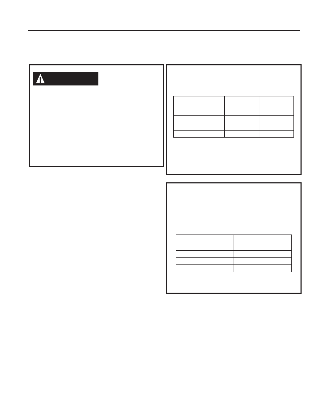
49-7774
Instrucciones de Instalación
INSTRUCCIONES DE INSTALACIÓN
OPCIONES DE CONEXIÓN ELÉCTRICA
DE 265 VOLTIOS
/DFRQH[LyQGHHVWHSURGXFWRGHYROWLRVGH&$
DXQFLUFXLWRGHULYDGR'(%(UHDOL]DUVHPHGLDQWHXQD
conexión directa de acuerdo a las indicaciones del NEC.
El código no permite enchufar esta unidad a una caja
externa.
(VWRVPRGHORVGHEHQLQVWDODUVHXWLOL]DQGRHONLWGH*(
de suministro de energía adecuado para el amperaje
de circuito derivado y el vatiaje deseado para el
FDOHIDFWRUGHUHVLVWHQFLDHOpFWULFD8WLOLFHOD7$%/$'(
&21(;,21(6(/e&75,&$6HQODSiJLQDSDUD
GHWHUPLQDUFXiOHVHONLWQHFHVDULR'HEHXWLOL]DUVHXQR
de los siguientes métodos de instalación.
A. PARA UNA INSTALACIÓN
SUB-BASE
Kits de sub-base eléctricos están disponibles para brindar un
cerramiento flexible para la conexión directa.
/DVLQVWUXFFLRQHVSURYLVWDVFRQHONLWGHVXEEDVH
seleccionado se deben seguir de forma cuidadosa. Es
responsabilidad del instalador asegurar que la conexión
de los componentes sea realizada de acuerdo con estas
instrucciones y siguiendo todos los códigos de electricidad.
B. PARA UNA INSTALACIÓN CON
CONEXIÓN DIRECTA
Si no se utilizará una sub-base eléctrica, la conexión directa
al cableado del circuito de empalmes dentro de la caja de
empalmes provista deberá ser realizada de acuerdo con los
siguientes pasos.
2UGHQHHOVLJXLHQWH.LWSDUDODFRQH[LyQGLUHFWDGH
voltios, según lo requerido:
Revise las instrucciones de instalación provistas con el
FDEOHGHFRUULHQWHRFRQORVNLWVGHFRQH[LyQGLUHFWDSDUD
acceder a instrucciones detalladas sobre el ensamble.
ADVERTENCIA
Calificación del Cir-
cuito de Empalmes
y del Amperaje de la
Unidad
Kit Adecuado
de la Sub-base
de GE
Kit de s
uministro de
corriente
5$.( 5$.3
5$.( 5$.3
5$.( 5$.3
Calificación del Circuito de
Empalmes y del Amperaje
de la Unidad
Kit de suministro de cor-
riente
5$.'
5$.'
5$.'
49-7774
Instrucciones de Instalación
INSTRUCCIONES DE INSTALACIÓN
CUADRO DE CONEXIÓN DE CORRIENTE
Conexiones del Cable de Corriente
Conexiones Directas
Kits de Suministro de
Corriente de 230/208
Voltios (2)
Dispositivo de Protección del Circuito Potencia Eléctrica del Calentador a
230/208 Voltios
5$.'
5$.'
5$.'
)XVLEOHR'LV\XQWRUFRQ7LHPSRGH5HWUDVRGH$PSHUHV
)XVLEOHR'LV\XQWRUFRQ7LHPSRGH5HWUDVRGH$PSHUHV
)XVLEOHR'LV\XQWRUFRQ7LHPSRGH5HWUDVRGH$PSHUHV
.:
.:
.:9HQWLODGRU$OWR
.:9HQWLODGRU%DMR
Kits de Suministro
de Corriente de 265
Voltios
Dispositivo de Protección del Circuito Potencia Eléctrica del Calentador a 265
Voltios
5$.'
5$.'
5$.'
)XVLEOHR'LV\XQWRUFRQ7LHPSRGH5HWUDVRGH$PSHUHV
)XVLEOHR'LV\XQWRUFRQ7LHPSRGH5HWUDVRGH$PSHUHV
)XVLEOHR'LV\XQWRUFRQ7LHPSRGH5HWUDVRGH$PSHUHV
.:
.:
.:9HQWLODGRU$OWR
.:9HQWLODGRU%DMR
8QDFDMDGHHPSDOPHVHVLQFOXLGDFRQORVNLWV63
8QDFDMDGHHPSDOPHVHVLQFOXLGDFRQHVWRVNLWV
3DUDXQD,QVWDODFLyQGH6XEEDVHGH9VLJDODUHIHUHQFLDGHOD&DMD$SiJLQDSDUDHOHPSDUHMDPLHQWRDGHFXDGRGHO
Kit de Suministro de Corriente de la Sub-base.
Kits de Suministro
de Corriente de
230/208 Voltios
con Dispositivo
de Detección de
Pérdida de Cor-
riente (1)
Configuración del
Enchufe de Pared
Dispositivo de Protección del Circuito Potencia Eléctrica del Calenta-
dor a 230/208 Voltios
5$.363
5$.363
5$.363
Tándem
Perpendicular
Tándem Grande
)XVLEOHR'LV\XQWRUFRQ7LHPSRGH5HWUDVRGH$PSHUHV
)XVLEOHR'LV\XQWRUFRQ7LHPSRGH5HWUDVRGH$PSHUHV
)XVLEOHR'LV\XQWRUFRQ7LHPSRGH5HWUDVRGH$PSHUHV
.:
.:
.:9HQWLODGRU$OWR
.:9HQWLODGRU%DMR
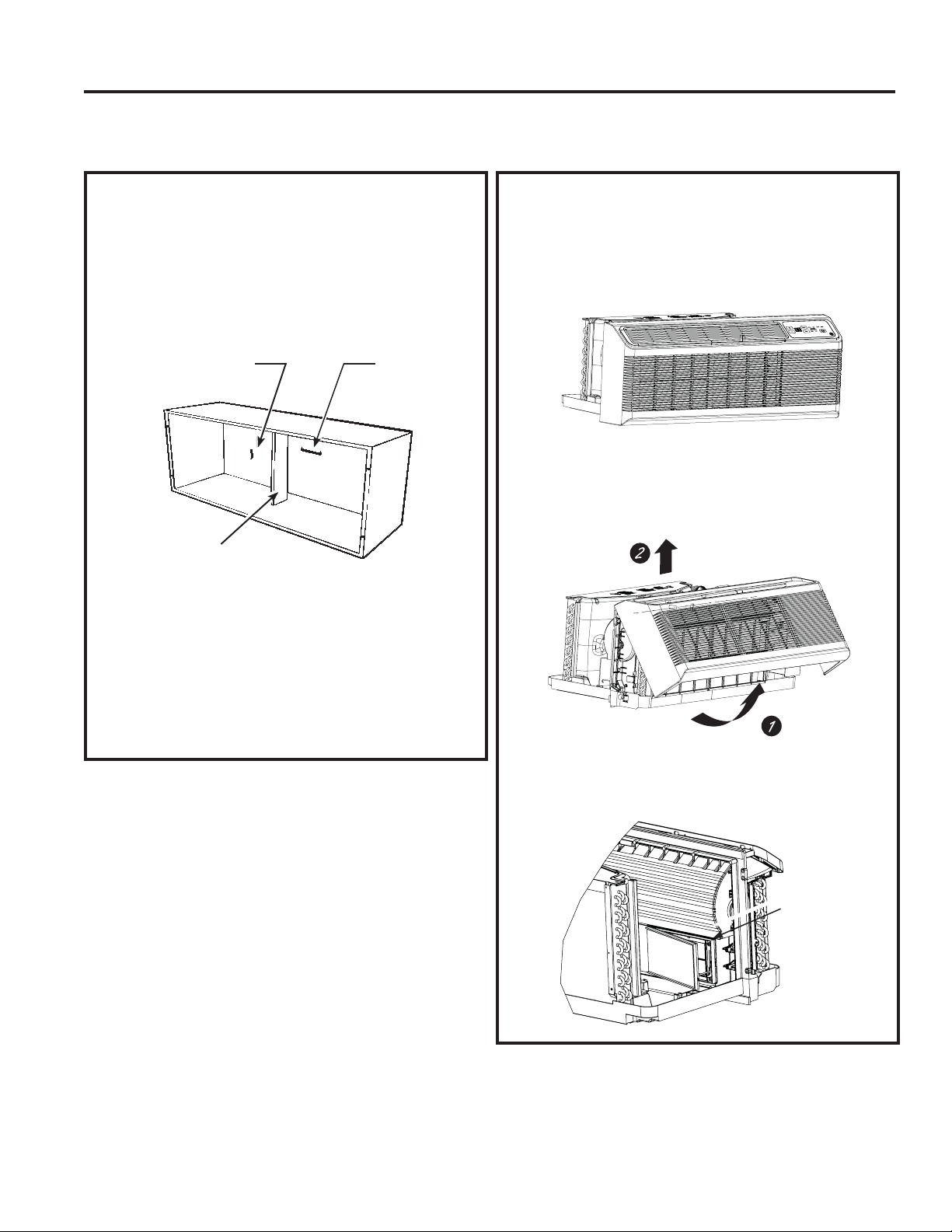
49-7774
Instrucciones de Instalación
INSTRUCCIONES DE INSTALACIÓN
1. INSTALE LA CAJA DE PARED
Y LA PARRILLA EXTERNA
/DFDMDGHSDUHGGHODVHULH5$%$%R5$%$%
debe ser correctamente instalada de acuerdo con las
instrucciones embaladas con la caja.
• Retire el refuerzo corrugado y el panel de protección
externa. Use la hendidura del panel externo como
sujeción y empuje hacia afuera.
• Instale la parrilla externa del costado del acondicionador
de aire de pared, siguiendo las instrucciones embaladas
con la parrilla.
NOTA: Para la instalación con una sub-base o un
adaptador de conducto, consulte las instrucciones
HPEDODGDVFRQHVWRVNLWV
2. PREPARE LA UNIDAD
• Con cuidado, retire la los bloques de gomaespuma
del embalaje que se encuentran en el frente del
acondicionador de aire de pared, del compresor y del
ventilador externo. Es posible que haya varios bloques y
cinta de piezas de embalaje que deban ser retiradas.
• Retire la tapa del acondicionador de aire de pared,
empujando hacia afuera en la parte inferior para liberarlo
OXHJROHYDQWHHOPLVPRSDUDGHVSHMDUHOULHODORODUJR
de la parte superior de la unidad (2).
• Si la puerta de la ventilación quedará funcional, retire
los tornillos enviados del lado frontal de la puerta de
ventilación, si está presente.
INSTALACIÓN DEL ZONELINE
Cinta de embalaje
(las ubicaciones
pueden variar)
Retire los
tornillos
enviados (si
se desea esta
operación)
Refuerzo
Panel
protector
Hendidura
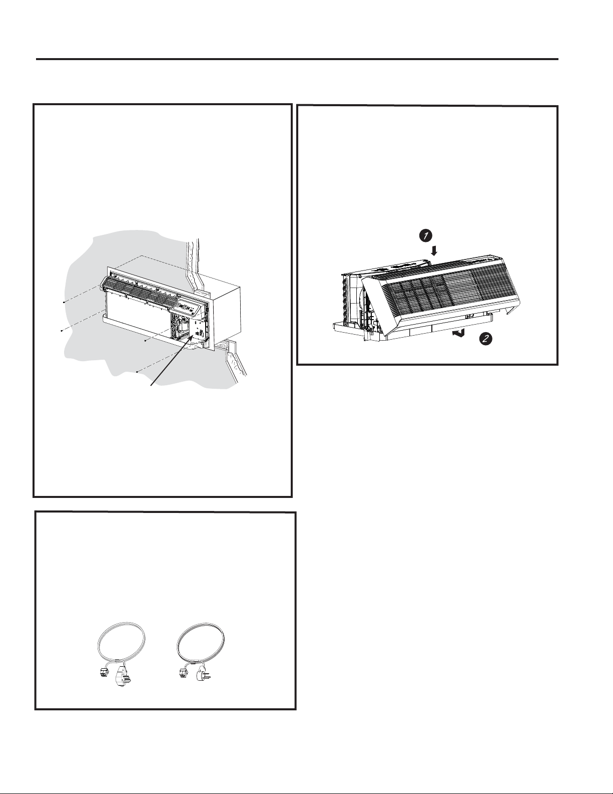
49-7774
INSTRUCCIONES DE INSTALACIÓN
INSTALACIÓN DEL ZONELINE (CONT.)
3. INSTALE LA UNIDAD EN LA
CAJA DE PARED
'HVOLFHODXQLGDGHQODFDMDGHSDUHG\DVHJXUHODPLVPD
con cuatro tornillos a través de los agujeros de la lengüeta
de la unidad.
/RVFXDWURWRUQLOORVHVWDUiQXELFDGRVHQXQDEROVDVHOODGD
que está apoyada debajo del panel de control, sobre el
bolsillo de la bandeja de la base.
5. REEMPLACE EL FRENTE
DEL ACONDICIONADOR
DE AIRE DE PARED
Reinstale la tapa del acondicionador de aire de pared,
alineando y colocando el riel superior de la tapa del
DFRQGLFLRQDGRUGHDLUHGHSDUHGVREUHHOFKDVLV\
luego empujando el mismo en la parte inferior (2).
NOTA: Existen varios agujeros adicionales en las
lengüetas laterales de la unidad para la instalación en
otras cajas de pared que no sean de GE Appliances. A fin
de evitar daños en la aislación de la pestaña, el instalador
deberá usar un punzón u otra herramienta puntiaguda para
perforar la aislación en los agujeros apropiados antes de
instalar los tornillos de adhesión.
/RVFXDWURWRUQLOORVGHODFDMDGHSDUHGHVWDUiQ
encintados al bolsillo, frente a la caja de control.
4
. CONECTE EL CABLE
DE CORRIENTE O EL KIT
DE CONEXIÓN DIRECTA
Revise las instrucciones de instalación provistas con
HOFDEOHGHFRUULHQWHRFRQORVNLWVGHFRQH[LyQGLUHFWD
para acceder a instrucciones detalladas sobre el
ensamble.
Kit de suministro de corriente (el aspecto puede variar)
Instrucciones de Instalación
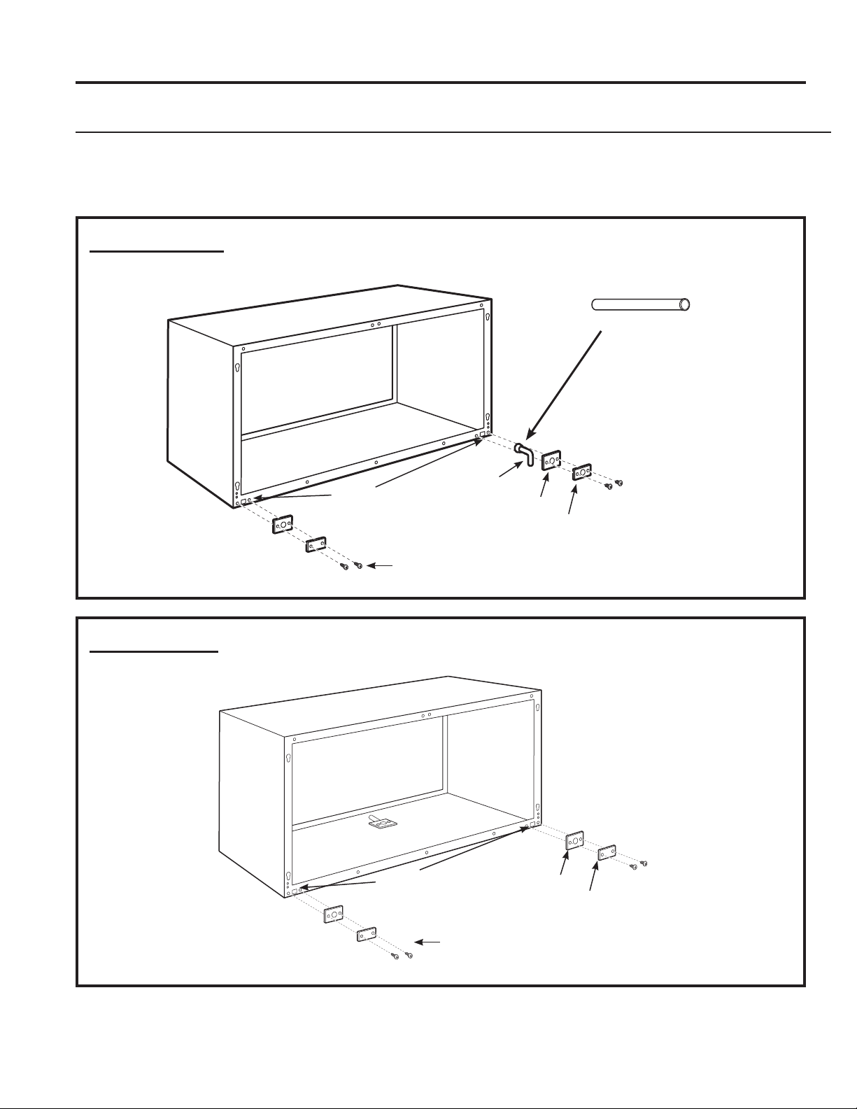
22 49-7774
Instrucciones de Instalación
INSTRUCCIONES DE INSTALACIÓN
OPCIONAL – INSTALACIÓN DEL KIT DE DRENAJE
Los modelos de la Serie Dry Air 25 fueron diseñados para mejorar la deshumidificación en un 25%. Debido
a que mayor cantidad de humedad será eliminada del aire, existe mayor posibilidad de que el agua gotee
desde la caja de la pared con relación a una unidad estándar. Para evitar que esta agua gotee sobre las
paredes externas del edificio, recomendamos el uso de un Kit de Drenaje RAD10.
Drenaje Externo
Consulte las Instrucciones de
,QVWDODFLyQHQHONLW5$'
Drenaje Interno
Consulte las Instrucciones de
,QVWDODFLyQHQHONLW5$'
7\SH³$´VFUHZIRUPHWDOFDVHRU
7\SH³%´VFUHZIRUPROGHGFDVH
Square
drain holes
Agujeros
cuadrados
de drenaje
1HRSUHQHVSRQJHJDVNHW
Steel mounting plate
´2'GUDLQWXEH
Junta de neopreno
Placa de montaje
de acero
Tornillo tipo “A” para caja metálica o
WRUQLOOR7LSR³%´SDUDFDMDPROGHDGD
Sustituto:
Tubo recto de cobre
de 6” de longitud, con
diámetro externo de 6”
(El drenaje está ubicado debajo del
gabinete; la ubicación será determinada
en el campo).
49-7774 23
Consejos para la Solución de Problemas… Antes de solicitar el servicio técnico
CONSEJOS PARA LA SOLUCIÓN DE PROBLEMAS
¡Ahorre tiempo y dinero! Primero revise los cuadros que aparecen en las siguientes páginas y es posible que no necesite solicitar
reparaciones.
Problema Causa Posible Qué Hacer
El Zoneline no se inicia. La unidad está desenchufada. $VHJ~UHVHGHTXHHOHQFKXIHGHO=RQHOLQHHVWp
completamente enchufado en el tomacorriente.
El cable de corriente no está
conectado de manera firme.
Retire la tapa del acondicionador de aire de pared y
asegúrese de que el conector negro del extremo del
cable de corriente esté conectado de manera firme.
Se quemó el fusible/ el disyuntor
está activado
Controle la caja de fusibles/ disyuntor de su hogar y
reemplace el fusible o reinicie el disyuntor.
La unidad está esperando a que
el protector de sobrecarga del
compresor se reinicie.
(VWRHVQRUPDO(O=RQHOLQHHPSH]DUiDIXQFLRQDU
nuevamente luego de reiniciarse.
Corte de Corriente. Si se produce un corte de corriente, configure el control
GHPRGRHQ2))$SDJDGR8QDYH]UHVWDEOHFLGD
la corriente, configure el control de modo en la
configuración deseada.
Hay un retraso de tiempo por protección
(aproximadamente 3 minutos) a fin de evitar
activaciones en la sobrecarga del compresor. Por
esta razón, es posible que la unidad no comience
a calefaccionar o refrigerar de forma normal por 3
minutos luego de haber sido conectada nuevamente.
El interruptor del cable de
corriente eléctrica está activado.
Presione el botón RESET (Reiniciar) ubicado en el
enchufe del cable de corriente o en la caja cerca del
enchufe.
Si el botón RESET (Reiniciar) no permanece
FRQHFWDGRLQWHUUXPSDHOXVRGHO=RQHOLQH\
comuníquese con un técnico calificado del servicio.
El Zoneline no enfría ni
calienta como debería.
El flujo de aire está obstruido. Asegúrese que no haya cortinas, persianas ni muebles
TXHEORTXHHQODSDUWHIURQWDOGHO=RQHOLQH
El flujo de aire externo está
restringido o se lo hace circular
nuevamente.
Asegúrese de que la parrilla trasera no esté restringida.
Esto puede hacer que la unidad deje de realizar ciclos,
debido al protector de sobrecarga del compresor.
/DUHMLOODH[WHUQDGHEHFRQWDUFRQXQiUHDOLEUHPtQLPD
GHO/DVUHMLOODVTXHQRVHDQGH*($SSOLDQFHV
podrán restringir el funcionamiento adecuado.
Consulte a su vendedor para solicitar asistencia.
Es posible que el control
de temperatura no esté
correctamente configurado.
Cambia el control a una configuración más baja o más
alta. NOTA: Es posible que el limitador de temperatura
esté limitando el rango de temperatura..
El filtro de aire está sucio. /LPSLHHOILOWURSRUORPHQRVFDGDGtDV&RQVXOWHOD
sección de Instrucciones de Funcionamiento.
Es posible que el ambiente haya
estado caliente o frío.
&XDQGRHO=RQHOLQHVHHQFLHQGDSRUSULPHUDYH]
deberá dejar transcurrir un período de tiempo para que
el ambiente se enfríe o caliente.
El aire externo está entrando a la
habitación.
Configure el control de ventilación en la posición
cerrada. NOTA:/DVXQLGDGHVHTXLSDGDVFRQ
ventilación de reposición permitirán la entrada de
cierta cantidad de aire externo de forma continua en la
habitación.
Olor a quemado al iniciar
el funcionamiento de la
calefacción.
Polvo en la superficie de los
elementos de calefacción.
Esto puede generar un olor “a quemado” cuando se
LQLFLHHOIXQFLRQDPLHQWRGHODFDOHIDFFLyQ'HEHUi
desaparecer rápidamente.
49-7774
Consejos para la Solución de Problemas… Antes de solicitar el servicio técnico
CONSEJOS PARA LA SOLUCIÓN DE PROBLEMAS
Problema Causa Posible Qué Hacer
El aire no siempre está
fresco o caliente durante
el funcionamiento.
La bomba de calor no está
produciendo aire caliente.
(VWRHVQRUPDO/DERPEDGHFDORUSURGXFLUiDLUH
caliente pero no tan caliente como el aire producido
cuando el calor eléctrico de más alto costo sea usado.
Los Controles Auxiliares del
Smart Fan (Ventilador Inteligente)
pueden ser configurados en
ventilación continua.
Esto hace que el ventilador produzca aire a
temperatura ambiente, incluso cuando el compresor
o el calentador dejen de realizar ciclos. El movimiento
continuo del aire brinda un mejor control general de
la temperatura en el modo para refrescar. Consulte
Refrescar/ Calefaccionar con el Smart Fan (Ventilador
Inteligente) en la página 8.
El aire no se siente lo
suficientemente caliente
durante el funcionamiento
de la calefacción.
La bomba de calor sola produce
aire que se siente más frío que lo
deseado.
8VHOD2SFLyQGH&DOHIDFFLyQ(OpFWULFD(VWRDSDJD
la bomba de calor y calienta con calefacción eléctrica
únicamente. NOTA: El uso de esta opción resultará en
un mayor consumo de energía.
La unidad no produce
aire.
El Control Auxiliar del Smart Fan
(Ventilador Inteligente) puede ser
configurado en ciclos.
Consulte Refrescar/ Calefaccionar con el Smart Fan
(Ventilador Inteligente) en la página 8.
Las funciones de
calefacción eléctrica y
ventilador no funcionan.
El cable de corriente no está
conectado de manera firme.
Retire la tapa del acondicionador de aire de pared y
asegúrese de que el conector negro del extremo del
cable de corriente esté conectado de manera firme.
La pantalla de temperatura
titila.
Es posible que el compresor haya
fallado.
&RQILJXUHHOFRQWUROGHIXQFLRQDPLHQWRHQ2))
(Apagado) y luego reinicie la unidad. Si la luz titilante
YXHOYHDDSDUHFHUGHQWURGHORVPLQXWRVOODPHDO
servicio técnico.
La unidad no funciona
luego de reinstalar el
Termostato de la Pared
Remota.
El modo 6 auxiliar no está
configurado correctamente.
Verifique que el cableado del TStat de la Pared
Remota sea el correcto al conector del termostato de
la unidad.
Las conexiones del termostato de
la unidad son incorrectos.
Controle el modo 6 auxiliar para asegurarse de que el
interruptor esté “activado” para el Termostato Remoto;
FRQVXOWHODSiJLQD
El transformador se desactiva o
activa de forma corta.
Espere 5 minutos para verificar si la corriente se
reinicia.
La bomba de calefacción
funciona con calor
electrónico sólo durante
la calefacción.
El Modo Aux. 6 no está
correctamente configurado.
El control del Modo Aux. 6 fue configurado para
el termostato de pared remoto apropiado, ya sea
“ “ para refrigeración/ calefacción “ “ Cambio
Automático”; consulte la página 8.
El Modo Aux. 8 no está
correctamente configurado.
Controle el Modo Aux. 8 y asegúrese de que la palanca
esté en “off” (apagada) para el funcionamiento de la
bomba de calor; consulte la página 9.
¡Ahorre tiempo y dinero! Primero revise los cuadros que aparecen en las siguientes páginas y es posible que no necesite solicitar
reparaciones.
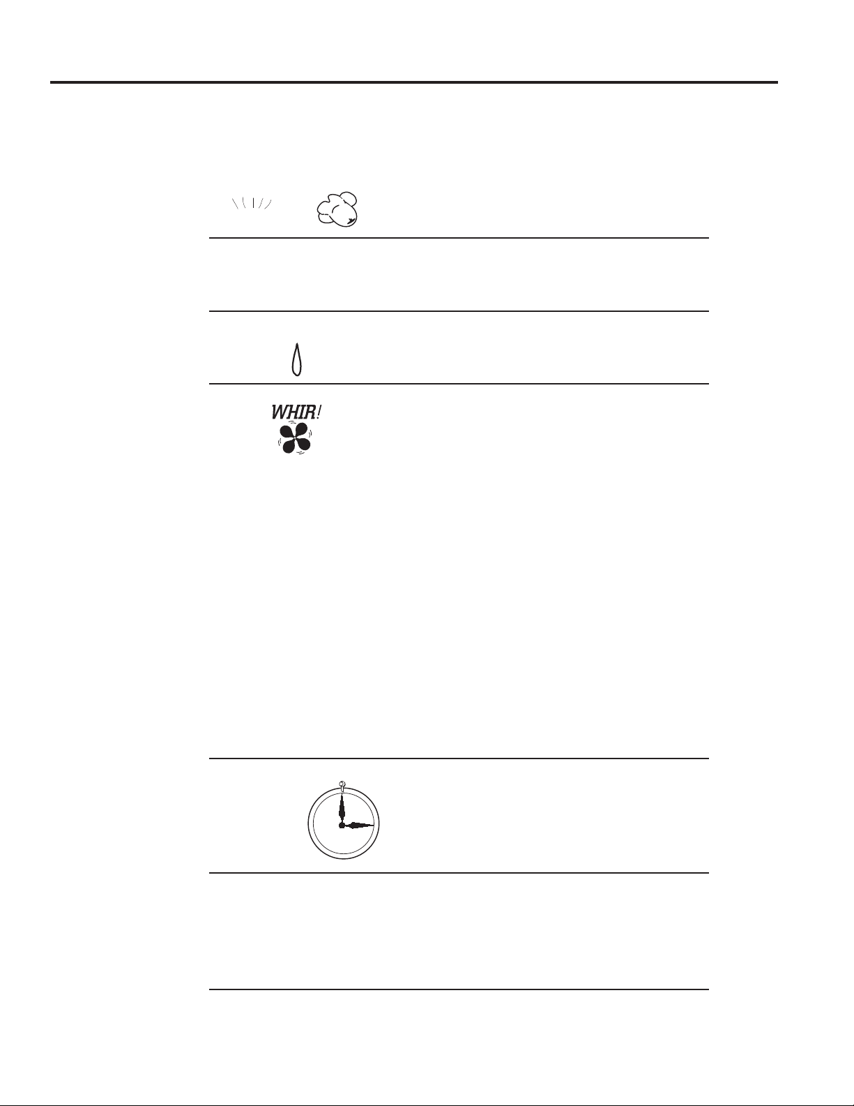
49-7774 25
Cosas que son normales
CONSEJOS PARA LA SOLUCIÓN DE PROBLEMAS
Sonidos de Funcionamiento Normal
Es posible que escuche un sonido de ¡ping! ocasionado
por el agua recogida y arrojada contra el condensador
en días lluviosos o cuando el nivel de humedad sea alto.
Esta función ayuda a eliminar la humedad y mejorar el
nivel de eficiencia.
Es posible que escuche sonidos de clic del relé cuando
se realice el ciclo de encendido y apagado de los
controles o cuando sean ajustados para cambiar la
temperatura del ambiente.
Se acumulará agua en la bandeja de la base cuando el
nivel de humedad sea alto o en días lluviosos. Es posible
que el agua se desborde y gotee desde el lado externo
de la unidad.
El ventilador interno funciona de forma continua cuando
la unidad está operando el modo para refrescar, a
menos que el Control Auxiliar del Smart Fan (Ventilador
Inteligente) esté configurado en la función de ciclos.
Esto hará que el ventilador se encienda y apague con
el compresor. También podrá escuchar el ruido de
detención o inicio de un ventilador.
Hay momentos en que el ventilador de la unidad
funcionará de forma pareja cuando la unidad no esté
calentando ni refrescando. Si el sistema es configurado
para funcionar con ventilador continuo, el ventilador
interno funcionará sin importar que la unidad esté
UHJUHVFDQGRRFDOHIDFFLRQDQGR2WUDVYHFHVHO
ventilador funcionará por más tiempo que el ciclo de
calefacción/ refrigeración o se iniciará ocasionalmente.
Esto es normal y es realizado para mejorar el confort y
balance del ambiente.
Si la unidad está equipada con un sistema de ventilación
de aire de reposición, los ventiladores funcionarán de
manera continua.
/DXQLGDGGHDLUHGHUHSRVLFLyQGLJLWDOUHDOL]DUiXQ
control del sistema sobre el encendido, sobre el ciclo
de corriente, y una vez cada 7 días si la unidad se
encuentra en el modo de ocupación. El control del
VLVWHPDGXUDDSUR[LPDGDPHQWHVHJXQGRV'XUDQWH
este tiempo, los ventiladores se acelerarán, reducirán su
velocidad, y luego irán al punto de configuración.
Es posible que note algunos minutos de retraso en el
LQLFLRVLLQWHQWDUHLQLFLDUHO=RQHOLQHGHPDVLDGRSURQWR
luego de apagarlo o si ajusta el termostato junto después
de apagar el compresor. Esto se debe a que un protector
de reinicio incorporado para el compresor genera un
retraso de 3 minutos.
'XUDQWHHOFLFORGHGHVFRQJHODFLyQWDQWRHOYHQWLODGRU
interno como el externo se detendrán y el compresor
funcionará en el modo de refrigeración para
HOLPLQDUHVFDUFKDGHODERELQDH[WHUQD/XHJRGHOD
descongelación, la unidad se reiniciará en el modo de
calefacción eléctrica para calentar de forma rápida la
habitación en el nivel de confort deseado.
Para proteger el compresor y evitar ciclos cortos, la
unidad fue diseñada para funcionar durante un mínimo
de 3 minutos luego de que el compresor se inicie en
cualquier configuración del termostato.
Retraso de
3 Minutos
³&/,&.´
6,/(1&,2
3527(&&,Ï1
'(/&2035(625
¡Ping!
*27(2
¡Pop!

26 49-7774
Nota
NOTA
49-7774 27
ACCESSORIOS
Garantía del Zoneline de GE Appliances
Ŷ9LDMHVGHOWpFQLFRGHOVHUYLFLRDVXKRJDUSDUDHQVHxDUOH
sobre el uso del producto.
Ŷ,QVWDODFLyQHQWUHJDRPDQWHQLPLHQWRLQDGHFXDGRV
Si tiene un problema de instalación o el aire
acondicionado no posee la capacidad de refrigeración
adecuada con relación al uso deseado, contacte a su
vendedor minorista o instalador. Usted es responsable de
brindar instalaciones de conexión eléctrica adecuadas.
Ŷ(QXELFDFLRQHVFRPHUFLDOHVHOWUDEDMRQHFHVDULRSDUD
trasladar la unidad a una ubicación donde esté accesible
para que un técnico pueda brindarle el servicio.
Ŷ)DOODVRGDxRVTXHUHVXOWHQGHODFRUURVLyQGHELGRD
la instalación en un ambiente donde haya químicos
corrosivos.
Ŷ5HHPSOD]RGHIXVLEOHVRUHLQLFLRGHGLV\XQWRUHV
Ŷ)DOODGHOSURGXFWRFRPRUHVXOWDGRGHPRGLILFDFLRQHVHQ
el mismo o debido a un uso irrazonable, incluyendo la
falta de mantenimiento razonable o necesario.
Ŷ)DOODVRGDxRVFRPRUHVXOWDGRGHODFRUURVLyQGHELGRD
instalaciones en ambientes costeros, excepto los modelos
tratados con protección anticorrosiva con aplicación
especial de fábrica, de acuerdo con lo designado en el
número de modelo.
Ŷ'DxRVVREUHHOSURGXFWRRFDVLRQDGRVSRUXQQLYHOGH
suministro de voltaje inadecuado, accidente, incendio,
inundaciones o catástrofes naturales.
Ŷ'DxRVFRQVHFXHQWHVRLQFLGHQWDOHVVREUHODSURSLHGDG
personal causados por posibles defectos del
acondicionador de aire.
Ŷ'DxRFDXVDGROXHJRGHODHQWUHJD
Ŷ3URGXFWRQRDFFHVLEOHSDUDEULQGDUHOVHUYLFLRUHTXHULGR
Qué No Cubrirá GE Appliances:
Esta garantía se extiende al comprador original y a cualquier dueño subsiguiente de productos comprados para uso
hogareño dentro de EE.UU y Canadá. Si el producto está ubicado en un área donde no se encuentra disponible un
Proveedor Autorizado del Servicio Técnico de GE Appliances, usted será responsable por el costo de un viaje o se podrá
requerir que traiga el producto a una ubicación del Servicio Técnico de GE Appliances Autorizado para recibir el servicio.
(Q$ODVNDODJDUDQWtDH[FOX\HHOFRVWRGHHQYtRROODPDGDVGHOVHUYLFLRDVXKRJDU
Algunos estados o provincias no permiten la exclusión o limitación de daños fortuitos o consecuentes. Esta garantía le da
derechos legales específicos, y es posible que tenga otros derechos legales que varían entre un estado y otro, o entre
una provincia y otra. Para conocer cuáles son sus derechos legales, consulte a la oficina de asuntos del consumidor local,
estatal o provincial o al Fiscal de su estado.
Garante : GE Appliances, a Haier company
Todo el servicio de garantía es provisto por nuestros Centros de Servicio de Fabricación, o un técnico autorizado del Servicio al
Cliente (Customer Care®). Para programar una visita del servicio técnico a través de Internet, visítenos en GEAppliances.com, o
OOiPHQRVDO*(37$&R3DUDDFFHGHUDOVHUYLFLRWpFQLFRHQ&DQDGiFRPXQtTXHVHFRQ*RUGRQ:LOOLDPV
&RUS$W&XDQGROODPHSDUDVROLFLWDUHOVHUYLFLRWHQJDORVQ~PHURVGHVHULH\PRGHORGLVSRQLEOHV
EXCLUSIÓN DE GARANTÍAS IMPLÍCITAS—Su única y exclusiva alternativa es la reparación del producto,
como se indica en la Garantía Limitada. Las garantías implícitas, incluyendo garantías implícitas de
comerciabilidad o conveniencia sobre un propósito particular, se limitan a un año o al período más corto
permitido por la ley.
Por el Período de: GE Appliances Reemplazará:
Un Año
Desde la fecha
de compra original
Cualquier parte del acondicionador de aire que falle debido a un defecto en los materiales o la
fabricación. Durante esta garantía limitada de un año, GE Appliances proveerá, sin costo,
todo el trabajo y los costos del servicio relacionados con el reemplazo de la pieza que presente
defectos.
Cinco Años
Desde la fecha
de compra original
El Sistema de Refrigeración Sellado, si cualquier pieza del sistema de refrigeración sellado
(el compresor, condensador, evaporador y todas las cañerías de conexión, incluyendo el siste-
ma de aire de reposición) falla debido a un defecto en los materiales o la fabricación. Durante
esta garantía limitada de cinco años, GE Appliances proveerá, sin costo, todo el trabajo y
los costos del servicio relacionados con el reemplazo de la pieza que presente defectos.
El Segundo al Quinto
Años
Desde la fecha
de compra original
Motores de Ventiladores, Interruptores, Termostato, Calentador, Protectores del Calen-
tador, Sobrecarga del Compresor, Solenoides, Tableros de Circuitos, Controles Auxili-
ares, Termistores, Centinela de Refrigeración, Controles de Congelamiento, Bomba ICR,
Capacitores, Varistores, Cojinetes del Ventilador Interno, si cualquiera de estas piezas falla
GHELGRDXQGHIHFWRHQORVPDWHULDOHVRODIDEULFDFLyQ'XUDQWHHVWDgarantía limitada adicio-
nal de cuatro años, el cliente será responsable por cualquier trabajo o costos relacionados con
el servicio técnico.

28 49-7774
Impreso en Estados Unidos
Soporte al Cliente
SOPORTE AL CLIENTE
GE Appliances Sitio Web
¢'HVHDUHDOL]DUXQDFRQVXOWDRQHFHVLWDD\XGDFRQVXHOHFWURGRPpVWLFR"£,QWHQWHDWUDYpVGHO6LWLR:HEGH(OHFWURGRPpVWLFRV
GH*($SSOLDQFHVODVKRUDVGHOGtDFXDOTXLHUGtDGHODxR8VWHGWDPELpQSXHGHFRPSUDUPiVJUDQGLRVRVSURGXFWRVGH
GE Appliances y sacar ventaja de todos nuestros servicios a través de Internet diseñados para su conveniencia. En EE.UU.:
GEAppliances.com
Registre su Electrodoméstico
¡Registre su electrodoméstico nuevo a través de Internet, según su conveniencia! Un registro puntual de su producto permitirá
una mejor comunicación y un servicio más puntual de acuerdo con los términos de su garantía, en caso de surgir la necesidad.
También puede enviar una carta en la tarjeta de inscripción pre-impresa que se incluye con el material embalado. En EE.UU.:
GEAppliances.com/register
Servicio Programado
El servicio de reparación de expertos de GE Appliances está a sólo un paso de su puerta. ¡Conéctese a través de Internet y
programe su servicio a su conveniencia cualquier día del año! En EE.UU.: GEAppliances.com/ge/service-and-support/service.
htmROODPHDOGXUDQWHHOKRUDULRFRPHUFLDOKDELWXDO
Garantías Extendidas
Adquiera una garantía extendida de GE Appliances y aprenda sobre descuentos especiales que están disponibles mientras su
JDUDQWtDD~QHVWiYLJHQWH/DSXHGHDGTXLULUHQFXDOTXLHUPRPHQWRDWUDYpVGH,QWHUQHW/RV6HUYLFLRVGH*($SSOLDQFHVD~Q
estarán allí cuando su garantía caduque. En EE.UU.: GEAppliances.com/ge/service-and-support/shop-for-extended-service-
plans.htmROODPHDOGXUDQWHHOKRUDULRFRPHUFLDOKDELWXDO
Conectividad Remota
Para solicitar asistencia con la conectividad de red inalámbrica (para modelos con activación remota), visite nuestro sitio Web en
GEAppliances.com/ge/connected-appliances/ROODPHDOHQ((88
Piezas y Accesorios
Individuos calificados para realizar el servicio técnico de sus propios electrodomésticos podrán solicitar el envío de piezas o
DFFHVRULRVGLUHFWDPHQWHDVXVKRJDUHVVHDFHSWDQODVWDUMHWDV9,6$0DVWHU&DUG\'LVFRYHU2UGHQHDWUDYpVGH,QWHUQHWKR\
GXUDQWHODVKRUDVGHOGtD(Q((88GEApplianceparts.com o por teléfono al 877.959.8688 durante el horario comercial
habitual.
Las instrucciones que figuran en este manual cubren los procedimientos que serán realizados por cualquier usuario.
Otros servicios técnicos generalmente deberían ser derivados a personal calificado del servicio. Se deberá tener
cuidado, ya que una reparación indebida podrá ocasionar que el funcionamiento no sea seguro.
Contáctenos
Si no se encuentra satisfecho con el servicio que recibió de GE Appliances, comuníquese con nosotros a través de nuestro sitio
Web con todos los detalles, incluyendo su número telefónico, o escriba a:
(Q((88*HQHUDO0DQDJHU&XVWRPHU5HODWLRQV_*($SSOLDQFHV$SSOLDQFH3DUN_/RXLVYLOOH.<5 GEAppliances.com/
ge/service-and-support/contact.htm

