
Owner's Manual
CRRFTSMRN°
j_]l I,
GARDEN TRACTOR
25.0 HE 48" Mower
Electric Start
Automatic Transmission
Model No.
917.276360
This product has a low emission engine which operates
[_ from built Before start the
differently previously engines. you
engine, read and understand this Owner's Manual.
IMPORTANT:
Read and follow all Safety
Rules and Instructions before
operating this equipment.
For answers to your questions
about this product, Call:
1-800-659-5917
Sears Craftsman Help Line
5 am - 5 pm, Mon - Sat
Sears, Roebuck and Co., Hoffman Estates, IL 60179 U.S.A.
Visit our Craftsman website:www.sears.com/craftsman
Warranty................................................2
SafetyRules..........................................3
ProductSpecifications...........................6
Assembly/Pre-Operation.......................7
Operation...............................................9
MaintenanceSchedule........................16
Maintenance........................................16
ServiceandAdjustments.....................21
Storage................................................29
Troubleshooting...................................30
RepairParts.........................................34
SearsService........................BackCover
LIMITEDWARRANTYONCRAFTSMANRIDINGEQUIPMENT
Fortwo (2)yearsfromthedate ofpurchase,if thisCraftsmanRidingEquipmentis
maintained,lubricatedandtuned upaccordingto theinstructionsin the owner'smanual,
Searswill repairorreplacefreeof chargeany partsthat arefoundto be defectivein
materialorworkmanshipaccordingto theguidelinesofcoveragelistedbelow.Searswill
alsoprovidefreelaborfortheseapplicablewarrantedpartsforthetwofullyears.During
thefirst 30 daysof purchase,therewill be nochargesto servicethe productatyour
homefor issuescoveredbythiswarranty.(Seeexclusionsbelow). Foryourconve-
nience, INHOMEwarrantyservicewill still be availableafterthe first 30 daysof pur-
chase,butatrip chargewillapply.Thischargewill bewaivedifthe Craftsmanproductis
droppedoffat an authorizedSearslocation.ForthenearestauthorizedSearslocation,
pleasecall 1-800-4-MY-HOME®.Thiswarrantyappliesonlywhile thisproductiswithin
the UnitedStates.
ThisWarrantydoesnotcover:
• Expendableitemswhichbecomewornduring normaluse,includingbutnotlimitedto
blades,spark plugs,air cleaners,belts,andoilfilters.
• StandardMaintenanceServicing,oil changes, ortune-ups.
• Tirereplacementorrepaircausedbypuncturesfromoutsideobjects,suchasnails,
thorns,stumps,orglass.
• Repairsnecessarybecauseof operatorabuse,includingbutnotlimitedto, damage
causedbytowingobjectsbeyondthecapabilityofthe ridingequipment,impacting
objectsthat bendtheframeorcrankshaft,or over-speedingthe engine.
• Repairsnecessarybecauseof operatornegligence,includingbutnotlimitedto,elec-
tricaland mechanicaldamagecausedbyimproperstorage,failureto usetheproper
gradeandamountofengineoil,failureto keepthe deckclearof flammabledebris,
orfailureto maintaintheequipmentaccordingtothe instructionscontainedinthe
owner'smanual.
• Engine(fuelsystem)cleaningor repairscausedbyfueldeterminedto becontami-
natedoroxidized(stale). In general,fuelshould beusedwithin30 daysof itspur-
chasedate.
• Normaldeteriorationandwearoftheexteriorfinishes,or productlabelreplacement.
• Ridingequipmentusedfor commercialor rentalpurposes.
LIMITEDWARRANTYON BATTERY
Forninety(90) daysfromdate ofpurchase,if anybatteryincludedwith thisridingequip-
mentprovesdefectivein materialorworkmanshipandourtestingdeterminesthebattery
will notholdacharge,Searswill replacethebatteryatno charge. Duringthe first30
daysofpurchase,therewillbe no chargesto replacethebatteryatyour HOME. After
thefirst 30 days,foryour convenience,IN-HOMEwarrantyservicewill stillbe avail-
ablebutatripchargewillapply. This chargewill bewaivedifthe Craftsmanproductis
droppedoff atan authorizedSearslocation.ForthenearestauthorizedSearslocation,
pleasecall 1-800-4-MY-HOME®.
Thisbatterywarrantyappliesonlywhile thisproductiswithinthe UnitedStates.
Thiswarrantygivesyou specificlegalrights,andyou mayalsohaveotherrights,which
vary,fromstateto state.
Sears,RoebuckandCo.,Dept.817WA,HoffmanEstates,IL 60179
IMPORTANT:Thiscuttingmachineiscapableofamputatinghandsandfeetandthrow-
ingobjects.Failureto observethefollowingsafetyinstructionscould resultin serious
injuryor death.
WARNING: Inorderto preventac-
cidentalstartingwhensetting up,trans-
porting,adjustingor makingrepairs,
alwaysdisconnectsparkplugwireand
placewirewhereitcannotcontactspark
plug.
WARNING: Donotcoastdowna
hillin neutral,you maylosecontrolofthe
tractor.
WARNING: Towonlytheattachments
that are recommendedbyand complywith
specificationsof themanufacturerofyour
tractor.Usecommonsensewhentowing.
Operateonlyat thelowestpossiblespeed
whenon aslope. Tooheavyofa load,
while on aslope,isdangerous.Tirescan
losetractionwiththe groundandcause
you to losecontrolofyour tractor.
WARNING:Engineexhaust, some
of its constituents, and certain vehicle
components contain or emit chemicals
known to the State of California to cause
cancer and birth defects or other reproduc-
tive harm.
WARNING: Battery posts, terminals
and related accessories contain lead and
lead compounds, chemicals known to the
State of California to cause cancer and
birth defects or other reproductive harm.
Wash hands after handling.
I. GENERAL OPERATION
• Read, understand, and follow all
instructions on the machine and in the
manual before starting.
• Do not put hands or feet near rotating
parts or under the machine. Keep clear
of the discharge opening at all times.
• Only allow responsible adults, who are
familiar with the instructions, to operate
the machine.
• Clear the area of objects such as
rocks, toys, wire, etc., which could be
picked up and thrown by the blades.
• Be sure the area is clear of bystand-
ers before operating. Stop machine if
anyone enters the area.
• Never carry passengers.
• Do not mow in reverse unless abso-
lutely necessary. Always look down
and behind before and while backing.
• Never direct discharged material
toward anyone. Avoid discharging
material against a wall or obstruction.
Material may ricochet back toward the
operator. Stop the blades when cross-
ing gravel surfaces.
• Do not operate machine without the
entire grass catcher, discharge guard,
or other safety devices in place and
working.
• Slow down before turning.
• Never leave a running machine
unattended. Always turn off blades,
set parking brake, stop engine, and
remove keys before dismounting.
• Disengage blades when not mowing.
Shut off engine and wait for all parts to
come to a complete stop before clean-
ing the machine, removing the grass
catcher, or unclogging the discharge
guard.
• Operate machine only in daylight or
good artificial light.
• Do not operate the machine while
under the influence of alcohol or drugs.
• Watch for traffic when operating near
or crossing roadways.
• Use extra care when loading or unload-
ing the machine into a trailer or truck.
• Always wear eye protection when oper-
ating machine.
• Data indicates that operators, age 60
years and above, are involved in a
large percentage of riding mower-re-
lated injuries. These operators should
evaluate their ability to operate the
riding mower safely enough to protect
themselves and others from serious
injury.
• Follow the manufacturer's recommen-
dation for wheel weights or counter-
weights.
• Keep machine free of grass, leaves or
other debris build-up which can touch
hot exhaust / engine parts and burn.
Do not allow the mower deck to plow
leaves or other debris which can cause
build-up to occur. Clean any oil or fuel
spillage before operating or storing the
machine. Allow machine to cool before
storage.
3
I1. SLOPE OPERATION
Slopes are a major factor related to loss of
control and tip-over accidents, which can
result in severe injury or death. Opera-
tion on all slopes requires extra caution. If
you cannot back up the slope or if you feel
uneasy on it, do not mow it.
• Mow up and down slopes, not across.
• Watch for holes, ruts, bumps, rocks, or
other hidden objects. Uneven terrain
could overturn the machine. Tall grass
can hide obstacles.
• Choose a low ground speed so that
you will not have to stop or shift while
on the slope.
• Do not mow on wet grass. Tires may
lose traction.
Always keep the machine in gear when
going down slopes. Do not shift to
neutral and coast downhill.
• Avoid starting, stopping, or turning on
a slope. If the tires lose traction, dis-
engage the blades and proceed slowly
straight down the slope.
• Keep all movement on the slopes slow
and gradual. Do not make sudden
changes in speed or direction, which
could cause the machine to roll over.
• Use extra care while operating ma-
chine with grass catchers or other at-
tachments; they can affect the stability
of the machine. Do no use on steep
slopes.
• Do not try to stabilize the machine by
putting your foot on the ground.
• Do not mow near drop-offs, ditches,
or embankments. The machine could
suddenly roll over if a wheel is over the
edge or if the edge caves in.
III, CHILDREN
Tragic accidents can occur if the operator
is not alert to the presence of children.
Children are often attracted to the machine
and the mowing activity. Never assume
that children will remain where you last
saw them.
• Keep children out of the mowing area
and in the watchful care of a respon-
sible adult other than the operator.
• Be alert and turn machine off if a child
enters the area.
• Before and while backing, look behind
and down for small children.
• Never carry children, even with the
blades shut off. They may fall off and
be seriously injured or interfere with
safe machine operation. Children who
have been given rides in the past may
suddenly appear in the mowing area
for another ride and be run over or
backed over by the machine.
• Never allow children to operate the
machine.
• Use extra care when approaching blind
corners, shrubs, trees, or other objects
that may block your view of a child.
IV. TOWING
• Tow only with a machine that has a
hitch designed for towing. Do not at-
tach towed equipment except at the
hitch point.
• Follow the manufacturer's recommen-
dation for weight limits for towed equip-
ment and towing on slopes.
• Never allow children or others in or on
towed equipment.
• On slopes, the weight of the towed
equipment may cause loss of traction
and loss of control.
• Travel slowly and allow extra distance
to stop.
V. SERVICE
SAFE HANDLING OF GASOLINE
To avoid personal injury or property
damage, use extreme care in handling
gasoline. Gasoline is extremely flammable
and the vapors are explosive.
• Extinguish all cigarettes, cigars, pipes,
and other sources of ignition.
• Use only approved gasoline container.
• Never remove gas cap or add fuel with
the engine running. Allow engine to
cool before refueling.
• Never fuel the machine indoors.
• Never store the machine or fuel con-
tainer where there is an open flame,
spark, or pilot light such as on a water
heater or other appliances.
• Never fill containers inside a vehicle
or on a truck or trailer bed with plastic
liner. Always place containers on the
ground away from your vehicle when
filling.
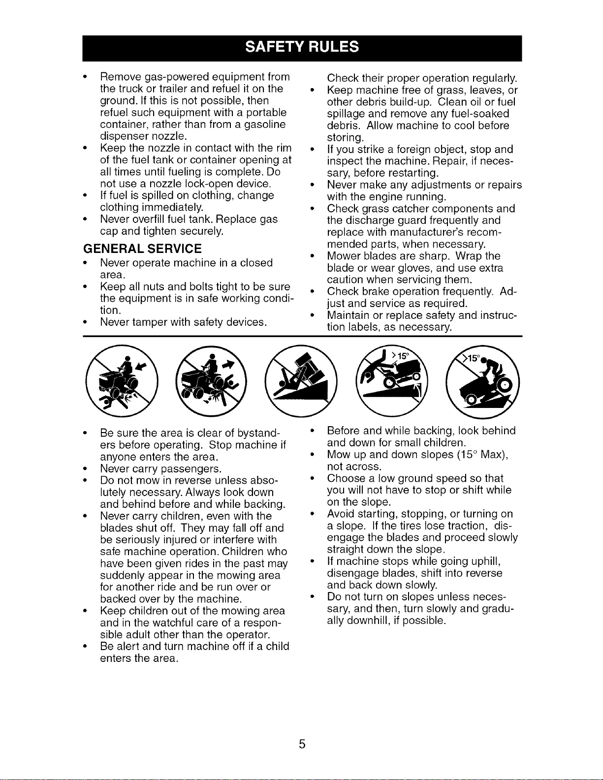
• Removegas-poweredequipmentfrom
thetruckortrailerandrefuelit onthe
ground.Ifthisisnotpossible,then
refuelsuchequipment with a portable
container, rather than from a gasoline
dispenser nozzle.
• Keep the nozzle in contact with the rim
of the fuel tank or container opening at
all times until fueling is complete. Do
not use a nozzle lock-open device.
• If fuel is spilled on clothing, change
clothing immediately.
• Never overfill fuel tank. Replace gas
cap and tighten securely.
GENERAL SERVICE
• Never operate machine in a closed
area.
• Keep all nuts and bolts tight to be sure
the equipment is in safe working condi-
tion.
• Never tamper with safety devices.
Check their proper operation regularly.
• Keep machine free of grass, leaves, or
other debris build-up. Clean oil or fuel
spillage and remove any fuel-soaked
debris. Allow machine to cool before
storing.
• If you strike a foreign object, stop and
inspect the machine. Repair, if neces-
sary, before restarting.
• Never make any adjustments or repairs
with the engine running.
• Check grass catcher components and
the discharge guard frequently and
replace with manufacturer's recom-
mended parts, when necessary.
• Mower blades are sharp. Wrap the
blade or wear gloves, and use extra
caution when servicing them.
• Check brake operation frequently. Ad-
just and service as required.
• Maintain or replace safety and instruc-
tion labels, as necessary.
• Be sure the area is clear of bystand-
ers before operating. Stop machine if
anyone enters the area.
• Never carry passengers.
• Do not mow in reverse unless abso-
lutely necessary. Always look down
and behind before and while backing.
• Never carry children, even with the
blades shut off. They may fall off and
be seriously injured or interfere with
safe machine operation. Children who
have been given rides in the past may
suddenly appear in the mowing area
for another ride and be run over or
backed over by the machine.
• Keep children out of the mowing area
and in the watchful care of a respon-
sible adult other than the operator.
• Be alert and turn machine off if a child
enters the area.
• Before and while backing, look behind
and down for small children.
• Mow up and down slopes (15 ° Max),
not across.
• Choose a low ground speed so that
you will not have to stop or shift while
on the slope.
• Avoid starting, stopping, or turning on
a slope. If the tires lose traction, dis-
engage the blades and proceed slowly
straight down the slope.
• If machine stops while going uphill,
disengage blades, shift into reverse
and back down slowly.
• Do not turn on slopes unless neces-
sary, and then, turn slowly and gradu-
ally downhill, if possible.
5
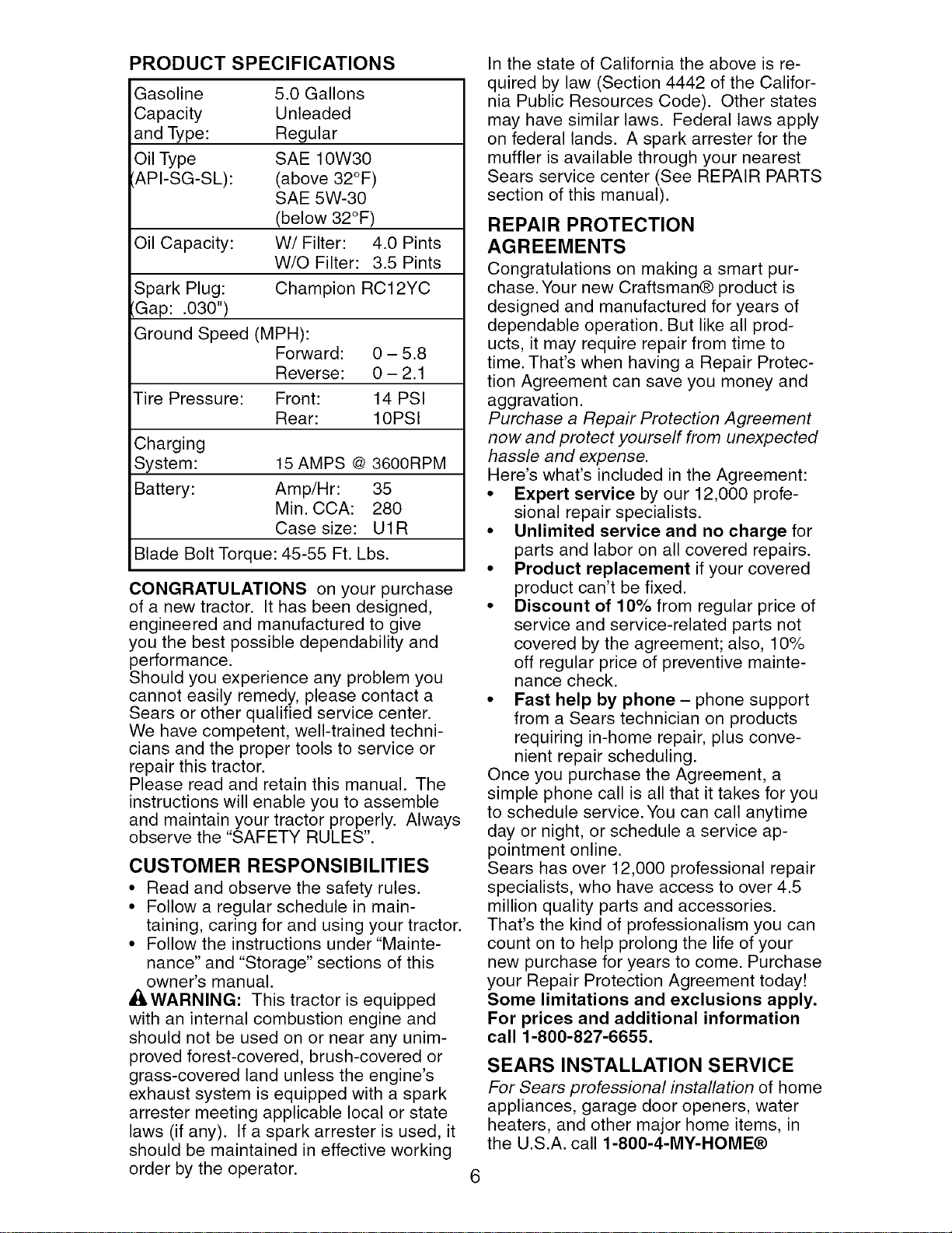
PRODUCT SPECIFICATIONS
Gasoline 5.0 Gallons
Capacity Unleaded
and Type: Regular
Oil Type SAE 10W30
'API-SG-SL): (above 32°F)
SAE 5W-30
(below 32°F)
Oil Capacity: W/Filter: 4.0 Pints
W/O Filter: 3.5 Pints
Spark Plug: Champion RC12YC
'Gap: .030")
Ground Speed (MPH):
Forward: 0 - 5.8
Reverse: 0 - 2.1
Tire Pressure: Front: 14 PSI
Rear: 10PSI
Charging
System: 15 AMPS @ 3600RPM
Battery: Amp/Hr: 35
Min. CCA: 280
Case size: U1R
Blade Bolt Torque: 45-55 Ft. Lbs.
CONGRATULATIONS on your purchase
of a new tractor. It has been designed,
engineered and manufactured to give
you the best possible dependability and
performance.
Should you experience any problem you
cannot easily remedy, please contact a
Sears or other qualified service center.
We have competent, well-trained techni-
cians and the proper tools to service or
repair this tractor.
Please read and retain this manual. The
instructions will enable you to assemble
and maintain your tractor properly. Always
observe the "SAFETY RULES".
CUSTOMER RESPONSIBILITIES
• Read and observe the safety rules.
• Follow a regular schedule in main-
taining, caring for and using your tractor.
• Follow the instructions under "Mainte-
nance" and "Storage" sections of this
owner's manual.
_,WARNING: This tractor is equipped
with an internal combustion engine and
should not be used on or near any unim-
proved forest-covered, brush-covered or
grass-covered land unless the engine's
exhaust system is equipped with a spark
arrester meeting applicable local or state
laws (if any). If a spark arrester is used, it
should be maintained in effective working
order by the operator.
In the state of California the above is re-
quired by law (Section 4442 of the Califor-
nia Public Resources Code). Other states
may have similar laws. Federal laws apply
on federal lands. A spark arrester for the
muffler is available through your nearest
Sears service center (See REPAIR PARTS
section of this manual).
REPAIR PROTECTION
AGREEMENTS
Congratulations on making a smart pur-
chase. Your new Craftsman® product is
designed and manufactured for years of
dependable operation. But like all prod-
ucts, it may require repair from time to
time. That's when having a Repair Protec-
tion Agreement can save you money and
aggravation.
Purchase a Repair Protection Agreement
now and protect yourself from unexpected
hassle and expense.
Here's what's included in the Agreement:
• Expert service by our 12,000 profe-
sional repair specialists.
• Unlimited service and no charge for
parts and labor on all covered repairs.
• Product replacement if your covered
product can't be fixed.
• Discount of 10% from regular price of
service and service-related parts not
covered by the agreement; also, 10%
off regular price of preventive mainte-
nance check.
• Fast help by phone- phone support
from a Sears technician on products
requiring in-home repair, plus conve-
nient repair scheduling.
Once you purchase the Agreement, a
simple phone call is all that it takes for you
to schedule service. You can call anytime
day or night, or schedule a service ap-
pointment online.
Sears has over 12,000 professional repair
specialists, who have access to over 4.5
million quality parts and accessories.
That's the kind of professionalism you can
count on to help prolong the life of your
new purchase for years to come. Purchase
your Repair Protection Agreement today!
Some limitations and exclusions apply.
For prices and additional information
call 1-800-827-6655.
SEARS INSTALLATION SERVICE
For Sears professional installation of home
appliances, garage door openers, water
heaters, and other major home items, in
the U.S.A. call 1-800-4-MY-HOME®
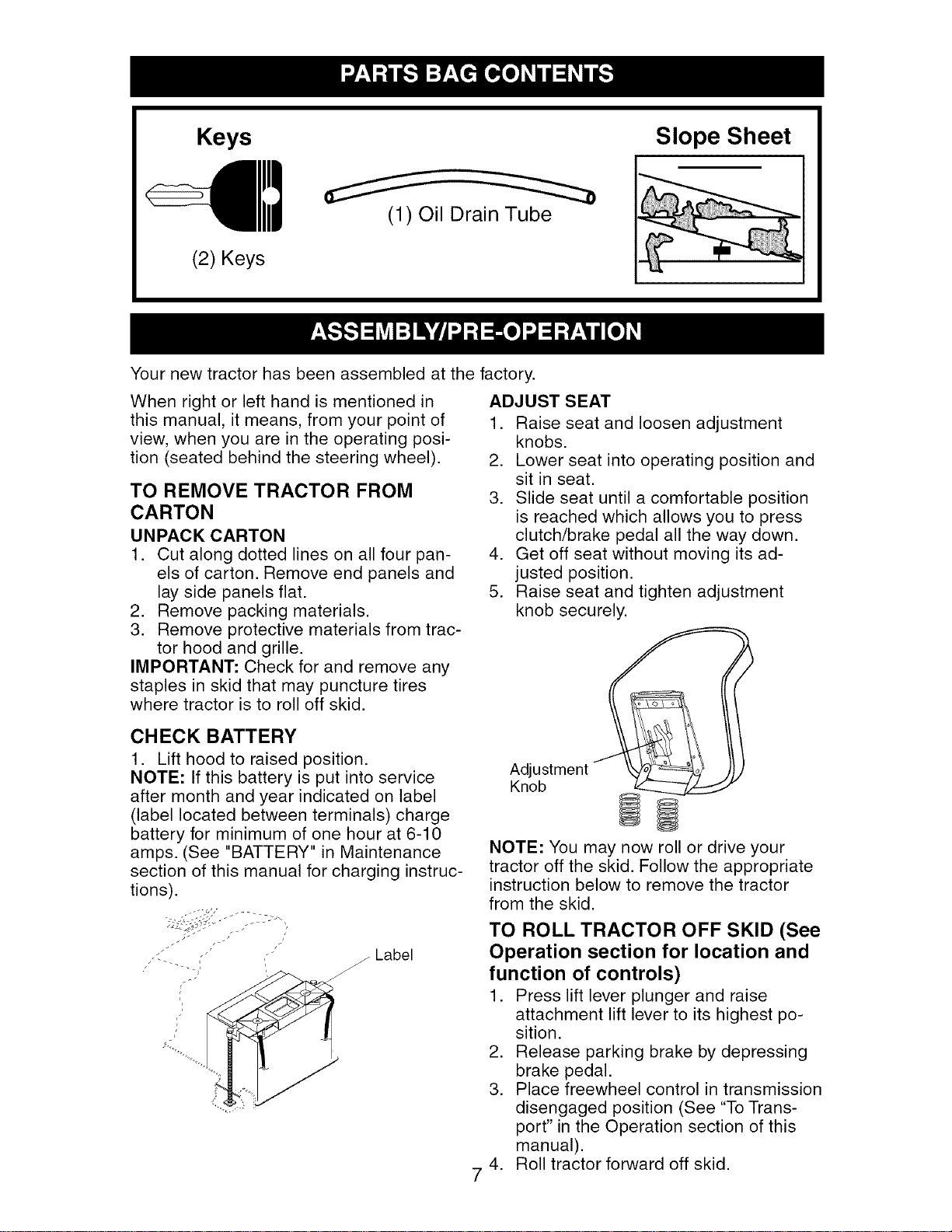
Keys Slope Sheet
(1) Oil Drain Tube
(2) Keys
Your new tractor has been assembled at the factory.
When right or left hand is mentioned in
this manual, it means, from your point of
view, when you are in the operating posi-
tion (seated behind the steering wheel).
TO REMOVE TRACTOR FROM
CARTON
UNPACK CARTON
1. Cut along dotted lines on all four pan-
els of carton. Remove end panels and
lay side panels flat.
2. Remove packing materials.
3. Remove protective materials from trac-
tor hood and grille.
IMPORTANT: Check for and remove any
staples in skid that may puncture tires
where tractor is to roll off skid.
CHECK BATTERY
1. Lift hood to raised position.
NOTE: If this battery is put into service
after month and year indicated on label
(label located between terminals) charge
battery for minimum of one hour at 6-10
amps. (See "BATTERY" in Maintenance
section of this manual for charging instruc-
tions).
. , _ Label
ADJUST SEAT
1. Raise seat and loosen adjustment
knobs.
2. Lower seat into operating position and
sit in seat.
3. Slide seat until a comfortable position
is reached which allows you to press
clutch/brake pedal all the way down.
4. Get off seat without moving its ad-
justed position.
5. Raise seat and tighten adjustment
knob securely.
7
Adjustment
Knob
NOTE: You may now roll or drive your
tractor off the skid. Follow the appropriate
instruction below to remove the tractor
from the skid.
TO ROLL TRACTOR OFF SKID (See
Operation section for location and
function of controls)
1. Press lift lever plunger and raise
attachment lift lever to its highest po-
sition.
2. Release parking brake by depressing
brake pedal.
3. Place freewheel control in transmission
disengaged position (See "To Trans-
port" in the Operation section of this
manual).
4. Roll tractor forward off skid.

TO DRIVE TRACTOR OFF SKID (See
Operation section for location and
_nction of controls)
WARNING: Before starting, read, un-
derstand and follow all instructions in the
Operation section of this manual. Be sure
tractor is in a well-ventilated area. Be sure
the area in front of tractor is clear of other
people and objects.
1. Be sure all the above assembly steps
have been completed.
2. Check engine oil level and fill fuel tank
with gasoline.
3. Place freewheel control in "trans-
mission engaged" position (See "To
Transport" in the Operation section of
this manual).
4. Sit on seat in operating position, de-
press brake pedal and set the parking
brake.
5. Press lift lever plunger and raise
attachment lift lever to its highest posi-
tion.
6. Start the engine. After engine has
started, move throttle control to idle
position.
7. Release parking brake.
8. Slowly move the motion control lever
forward and slowly drive tractor off
skid.
9. Apply brake to stop tractor and set
parking brake.
10.Turn ignition key to "STOP" position.
Continue with the instructions that follow.
CHECK TIRE PRESSURE
The tires on your tractor were overinflated
at the factory for shipping purposes. Cor-
rect tire pressure is important for best
cutting performance.
• Reduce tire pressure to PSI shown in
"PRODUCT SPECIFICATIONS" section
of this manual.
CHECK DECK LEVELNESS
For best cutting results, mower hous-
ing should be properly leveled. See "TO
LEVEL MOWER HOUSING" in the Service
and Adjustments section of this manual.
CHECK FOR PROPER POSITION
OF ALL BELTS
See the figures that are shown for replac-
ing motion and mower blade drive belts
in the Service and Adjustments section
of this manual. Verify that the belts are
routed correctly.
CHECK BRAKE SYSTEM
After you learn how to operate your trac-
tor, check to see that the brake is properly
adjusted. See "TO ADJUST BRAKE" in
the Service and Adjustments section of
this manual.
,/CHECKLIST
Before you operate your new tractor, we
wish to assure that you receive the best
performance and satisfaction from this
Quality Product.
Please review the following checklist:
,/All assembly instructions have been
completed.
,/No remaining loose parts in carton.
,/Battery is properly prepared and
charged. (Minimum 1 hour at 6 amps).
,/Seat is adjusted comfortably and tight-
ened securely.
,/All tires are properly inflated. (For ship-
ping purposes, the tires were overin-
flated at the factory).
,/Be sure mower deck is properly leveled
side-to-side/front-to-rear for best cutting
results. (Tires must be properly inflated
for leveling).
,/Check mower and drive belts. Be sure
they are routed properly around pulleys
and inside all belt keepers.
,/Check wiring. See that all connections
are still secure and wires are properly
clamped.
,/Before driving tractor, be sure freewheel
control is in "transmission engaged"
position (see "TO TRANSPORT" in the
Operation section of this manual).
While learning how to use your tractor, pay
extra attention to the following important
items:
,/Engine oil is at proper level.
,/Fuel tank is filled with fresh, clean, regu-
lar unleaded gasoline.
,/Become familiar with all controls, their
location and function. Operate them
before you start the engine.
,/Be sure brake system is in safe operat-
ing condition.
,/Be sure Operator Presence System
and Reverse Operation System (ROS)
are working properly (See the Opera-
tion and Maintenance sections in this
manual).
,/It is important to purge the transmission
before operating your tractor for the first
time. Follow proper starting and trans-
mission purging instructions (See "TO
START ENGINE" and "PURGE TRANS-
MISSION" in the Operation section of
this manual).
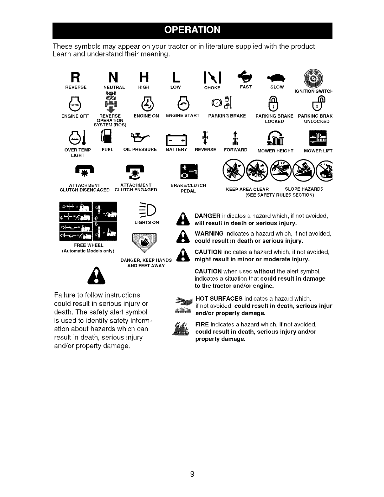
Thesesymbolsmayappearon yourtractoror inliteraturesuppliedwiththe product.
Learnand understandtheirmeaning.
R N H L I',,I
REVERSE NEUTRAL HIGH LOW CHOKE FAST
G G
ENGINE OFF REVERSE ENGINE ON ENGINE START PARKING BRAKE
OPERATION
SYSTEM (ROS)
ol
OVER TEMP
LIGHT
FUEL OIL PRESSURE BATTERY REVERSE
ATTACHMENT ATTACHMENT
CLUTCH DISENGAGED CLUTCH ENGAGED
FREE WHEEL
(Automatic Models only)
SLOW
IGNITION SWITCF
PARKING BRAKE PARKING BRAN
LOCKED UNLOCKED
BRAK_CLUTCH
PEDAL
t
FORWARD MOWER HEIGHT MOWER LIFT
KEEP AREA CLEAR SLOPE HAZARDS
(SEE SAFETY RULES SECTION)
LIGHTS ON
&
&
DANGER indicates a hazard which, if not avoided,
will result in death or serious injury.
WARNING indicates a hazard which, if not avoided,
could result in death or serious injury.
&
DANGER, KEEP HANDS
AND FEET AWAY
Failure to follow instructions
could result in serious injury or
death. The safety alert symbol
is used to identify safety inform-
ation about hazards which can
result in death, serious injury
and/or property damage.
CAUTION indicatesa hazard which, if not avoided,
might result in minor or moderate injury.
CAUTION when used without the alert symbol,
indicates a situation that could result in damage
to the tractor and/or engine.
HOT SURFACES indicatesa hazard which,
if not avoided, could result in death, serious injur
and/or property damage.
FIRE indicates a hazard which, if not avoided,
could result in death, serious injury and/or
property damage.
9
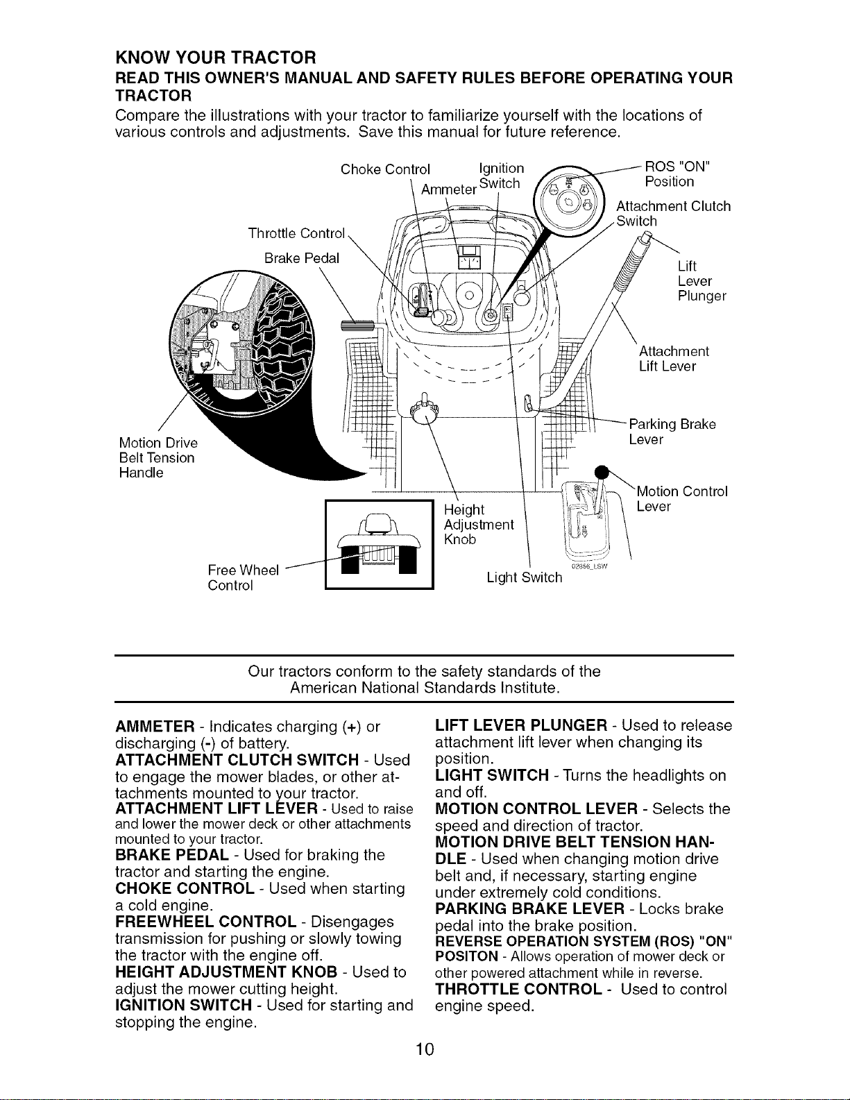
KNOW YOUR TRACTOR
READ THIS OWNER'S MANUAL AND SAFETY RULES BEFORE OPERATING YOUR
TRACTOR
Compare the illustrations with your tractor to familiarize yourself with the locations of
various controls and adjustments. Save this manual for future reference.
Choke Control Ignition "ON"
Ammeter Switch Position
Attachment Clutch
Brake Pedal
Lift
Lever
Plunger
Attachment
Lift Lever
Motion Drive
Belt Tension
Handle
Free Wheel
Control
Height
Adjustment
Knob
Light Switch
g Brake
Lever
Control
Lever
Our tractors conform to the safety standards of the
American National Standards Institute.
AMMETER - Indicates charging (+) or
discharging (-) of battery.
ATTACHMENT CLUTCH SWITCH - Used
to engage the mower blades, or other at-
tachments mounted to your tractor.
ATTACHMENT LIFT LEVER - Used to raise
and lower the mower deck or other attachments
mounted to your tractor.
BRAKE PEDAL - Used for braking the
tractor and starting the engine.
CHOKE CONTROL - Used when starting
a cold engine.
FREEWHEEL CONTROL - Disengages
transmission for pushing or slowly towing
the tractor with the engine off.
HEIGHT ADJUSTMENT KNOB - Used to
adjust the mower cutting height.
IGNITION SWITCH - Used for starting and
stopping the engine.
LIFT LEVER PLUNGER - Used to release
attachment lift lever when changing its
position.
LIGHT SWITCH - Turns the headlights on
and off.
MOTION CONTROL LEVER - Selects the
speed and direction of tractor.
MOTION DRIVE BELT TENSION HAN-
DLE - Used when changing motion drive
belt and, if necessary, starting engine
under extremely cold conditions.
PARKING BRAKE LEVER - Locks brake
pedal into the brake position.
REVERSE OPERATION SYSTEM (ROS) "ON"
POSlTON - Allows operation of mower deck or
other powered attachment while in reverse.
THROTTLE CONTROL - Used to control
engine speed.
10
SAFETYGLASSES
The operation of any tractor can result in foreign objects thrown into
the eyes, which can result in severe eye damage. Always wear safety
glasses or eye shields while operating your tractor or performing any
adjustments or repairs. We recommend standard safety glasses or a
wide vision safety mask worn over spectacles.
HOW TO USE YOUR TRACTOR
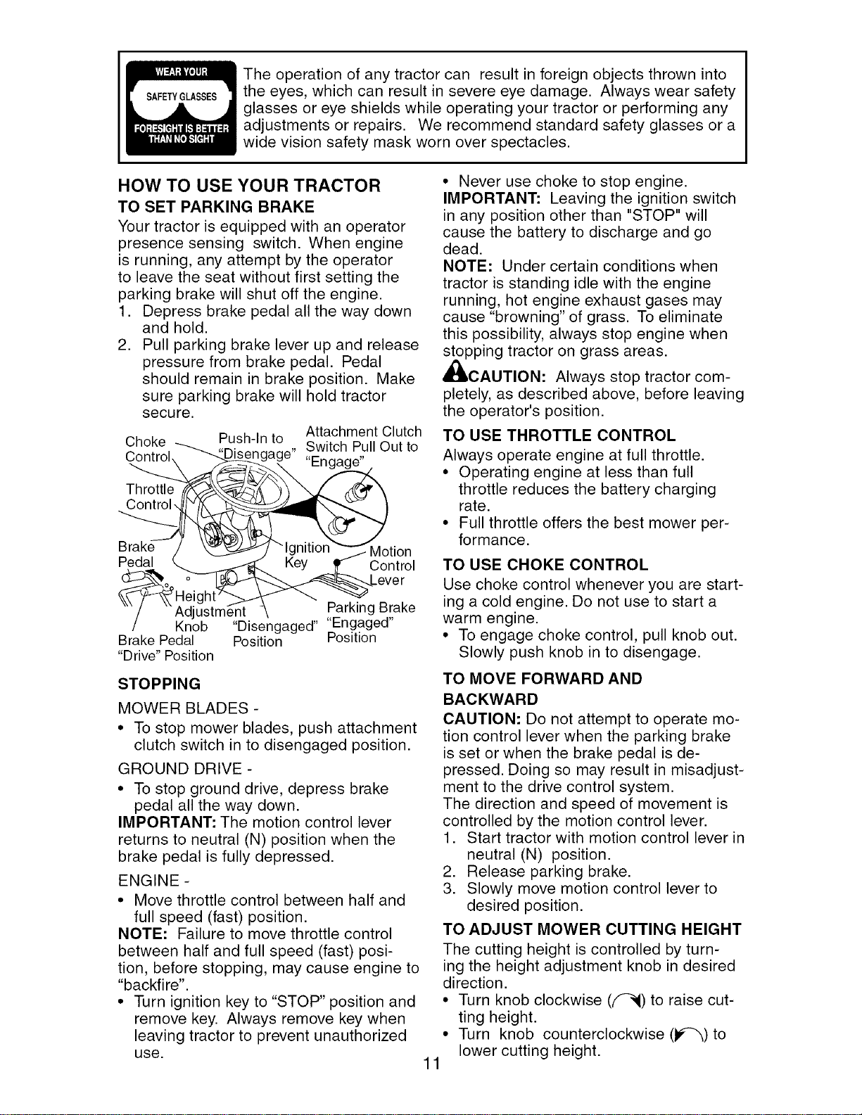
TO SET PARKING BRAKE
Your tractor is equipped with an operator
presence sensing switch. When engine
is running, any attempt by the operator
to leave the seat without first setting the
parking brake will shut off the engine.
1. Depress brake pedal all the way down
and hold.
2. Pull parking brake lever up and release
pressure from brake pedal. Pedal
should remain in brake position. Make
sure parking brake will hold tractor
secure.
Choke Push-In to Attachment Clutch
Control ngage" Switch Pull Out to
"Engage"
Throttle
Control
Pedal
Motion
Control
_ever
Adjustment Parking Brake
Knob "Disengaged" "Engaged"
Brake Pedal Position Position
"Drive" Position
STOPPING
MOWER BLADES -
• To stop mower blades, push attachment
clutch switch in to disengaged position.
GROUND DRIVE -
• To stop ground drive, depress brake
pedal all the way down.
IMPORTANT: The motion control lever
returns to neutral (N) position when the
brake pedal is fully depressed.
ENGINE -
• Move throttle control between half and
full speed (fast) position.
NOTE: Failure to move throttle control
between half and full speed (fast) posi-
tion, before stopping, may cause engine to
"backfire".
• Turn ignition key to "STOP" position and
remove key. Always remove key when
leaving tractor to prevent unauthorized
use.
11
• Never use choke to stop engine.
IMPORTANT: Leaving the ignition switch
in any position other than "STOP" will
cause the battery to discharge and go
dead.
NOTE: Under certain conditions when
tractor is standing idle with the engine
running, hot engine exhaust gases may
cause "browning" of grass. To eliminate
this possibility, always stop engine when
stopping tractor on grass areas.
_CAUTION: Always stop tractor com-
pletely, as described above, before leaving
the operator's position.
TO USE THROTTLE CONTROL
Always operate engine at full throttle.
• Operating engine at less than full
throttle reduces the battery charging
rate.
• Full throttle offers the best mower per-
formance.
TO USE CHOKE CONTROL
Use choke control whenever you are start-
ing a cold engine. Do not use to start a
warm engine.
• To engage choke control, pull knob out.
Slowly push knob in to disengage.
TO MOVE FORWARD AND
BACKWARD
CAUTION: Do not attempt to operate mo-
tion control lever when the parking brake
is set or when the brake pedal is de-
pressed. Doing so may result in misadjust-
ment to the drive control system.
The direction and speed of movement is
controlled by the motion control lever.
1. Start tractor with motion control lever in
neutral (N) position.
2. Release parking brake.
3. Slowly move motion control lever to
desired position.
TO ADJUST MOWER CUTTING HEIGHT
The cutting height is controlled by turn-
ing the height adjustment knob in desired
direction.
• Turn knob clockwise (_) to raise cut-
ting height.
• Turn knob counterclockwise (p_) to
lower cutting height.
Thecuttingheightrangeisapproximately
1-1/2"to4-1/2". Theheightsaremea-
suredfromthegroundtothe bladetipwith
theenginenotrunning.
These heightsare approximateandmay
varydependinguponsoilconditions,
heightof grassandtypesof grassbeing
mowed.
• Theaveragelawnshouldbecut to
approximately2-1/2 inchesduringthe
coolseasonandto over3 inchesduring
hotmonths. Forhealthierandbetter
lookinglawns,mowoftenandafter
moderategrowth.
• Forbestcutting performance,grassover
6 inchesin heightshouldbe mowed
twice. Makethefirst cut relativelyhigh;
thesecondto desiredheight.
TO ADJUST GAUGE WHEELS
Gauge wheels are properly adjusted
when they are slightly off the ground when
mower is at the desired cutting height in
operating position. Gauge wheels then
keep the deck in proper position to help
prevent scalping in most terrain conditions.
NOTE: Be sure tractor is on a flat level
surface.
1. Lower mower and adjust mower to
desired cutting height.
2. Remove retainer spring and clevis pin
which secure each gauge wheel bar.
3. Lower gauge wheels to ground. Raise
gauge wheels slightly to align holes
in bracket and gauge wheel bar and
insert clevis pin. Gauge wheels should
be slightly off the ground.
4. Replace retainer spring into clevis pin.
5. Be sure all gauge wheels are in the
same setting.
IMPORTANT: Be sure to readjust gauge
wheels if you change the cutting height
of the mower deck.
Retainer
Spring
C_vis
//
Pin
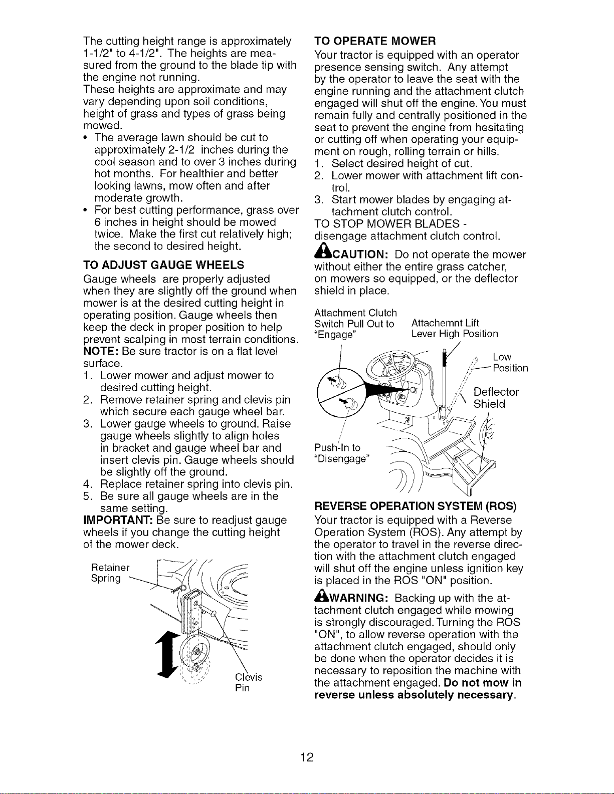
TO OPERATE MOWER
Your tractor is equipped with an operator
presence sensing switch. Any attempt
by the operator to leave the seat with the
engine running and the attachment clutch
engaged will shut off the engine. You must
remain fully and centrally positioned in the
seat to prevent the engine from hesitating
or cutting off when operating your equip-
ment on rough, rolling terrain or hills.
1. Select desired height of cut.
2. Lower mower with attachment lift con-
trol.
3. Start mower blades by engaging at-
tachment clutch control.
TO STOP MOWER BLADES -
disengage attachment clutch control.
CAUTION: Do not operate the mower
without either the entire grass catcher,
on mowers so equipped, or the deflector
shield in place.
Attachment Clutch
Switch Pull Out to Attachemnt Lift
"Engage" Lever High Position
/
/
/
/
Push:In to
"Disengage"
Deflector
Shield
REVERSE OPERATION SYSTEM (ROS)
Your tractor is equipped with a Reverse
Operation System (ROS). Any attempt by
the operator to travel in the reverse direc-
tion with the attachment clutch engaged
will shut off the engine unless ignition key
is placed in the ROS "ON" position.
,4_WARNING: Backing up with the at-
tachment clutch engaged while mowing
is strongly discouraged. Turning the ROS
"ON", to allow reverse operation with the
attachment clutch engaged, should only
be done when the operator decides it is
necessary to reposition the machine with
the attachment engaged. Do not mow in
reverse unless absolutely necessary.
12
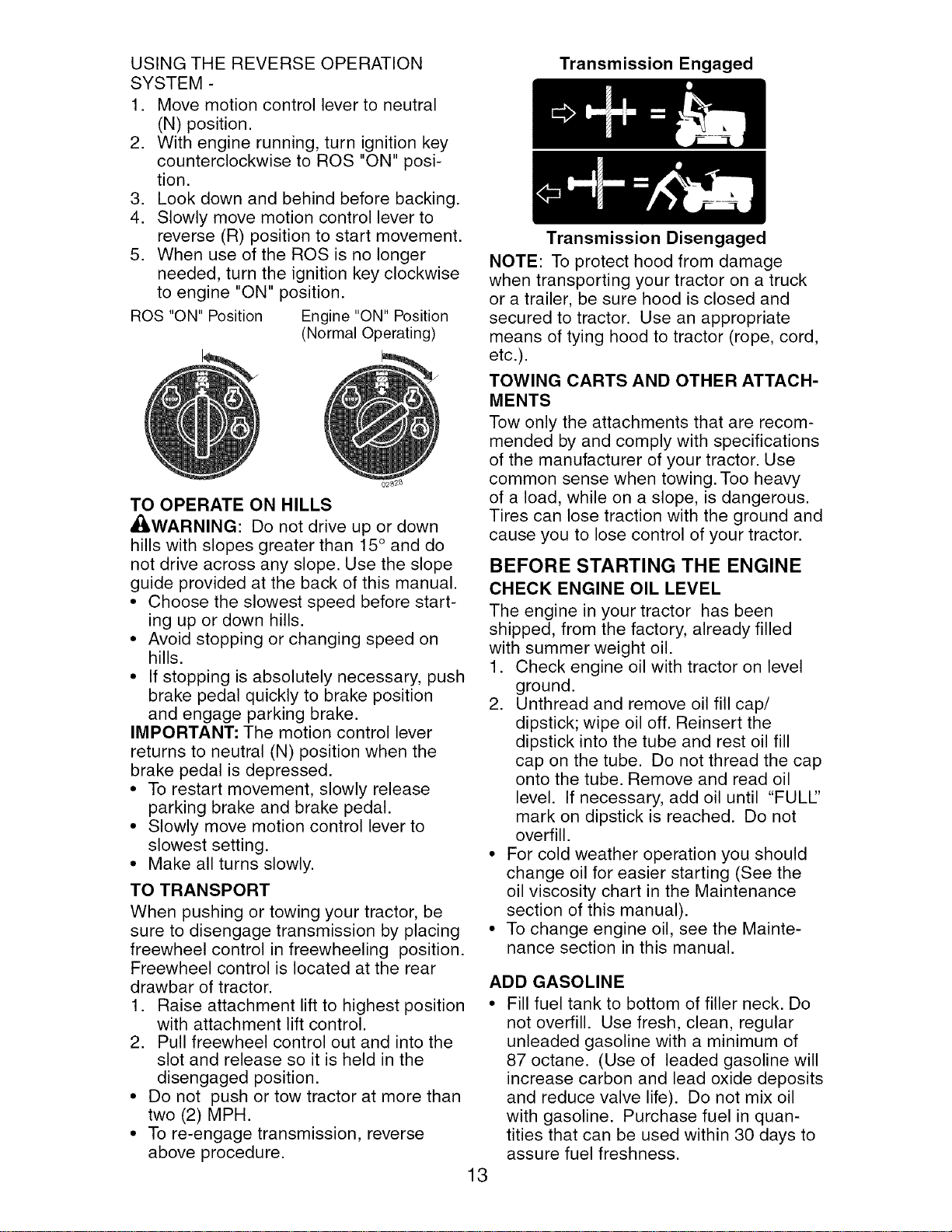
USING THE REVERSE OPERATION
SYSTEM -
1. Move motion control lever to neutral
(N) position.
2. With engine running, turn ignition key
counterclockwise to ROS "ON" posi-
tion.
3. Look down and behind before backing.
4. Slowly move motion control lever to
reverse (R) position to start movement.
5. When use of the ROS is no longer
needed, turn the ignition key clockwise
to engine "ON" position.
ROS "ON" Position Engine "ON" Position
(Normal Operating)
TO OPERATE ON HILLS
AI_,WARNING: Do not drive up or down
hills with slopes greater than 15 ° and do
not drive across any slope. Use the slope
guide provided at the back of this manual.
• Choose the slowest speed before start-
ing up or down hills.
• Avoid stopping or changing speed on
hills.
• If stopping is absolutely necessary, push
brake pedal quickly to brake position
and engage parking brake.
IMPORTANT: The motion control lever
returns to neutral (N) position when the
brake pedal is depressed.
• To restart movement, slowly release
parking brake and brake pedal.
• Slowly move motion control lever to
slowest setting.
• Make all turns slowly.
TO TRANSPORT
When pushing or towing your tractor, be
sure to disengage transmission by placing
freewheel control in freewheeling position.
Freewheel control is located at the rear
drawbar of tractor.
1. Raise attachment lift to highest position
with attachment lift control.
2. Pull freewheel control out and into the
slot and release so it is held in the
disengaged position.
• Do not push or tow tractor at more than
two (2) MPH.
• To re-engage transmission, reverse
above procedure.
13
Transmission Engaged
Transmission Disengaged
NOTE: To protect hood from damage
when transporting your tractor on a truck
or a trailer, be sure hood is closed and
secured to tractor. Use an appropriate
means of tying hood to tractor (rope, cord,
etc.).
TOWING CARTS AND OTHER ATTACH-
MENTS
Tow only the attachments that are recom-
mended by and comply with specifications
of the manufacturer of your tractor. Use
common sense when towing. Too heavy
of a load, while on a slope, is dangerous.
Tires can lose traction with the ground and
cause you to lose control of your tractor.
BEFORE STARTING THE ENGINE
CHECK ENGINE OIL LEVEL
The engine in your tractor has been
shipped, from the factory, already filled
with summer weight oil.
1. Check engine oil with tractor on level
ground.
2. Unthread and remove oil fill cap/
dipstick; wipe oil off. Reinsert the
dipstick into the tube and rest oil fill
cap on the tube. Do not thread the cap
onto the tube. Remove and read oil
level. If necessary, add oil until "FULl"
mark on dipstick is reached. Do not
overfill.
• For cold weather operation you should
change oil for easier starting (See the
oil viscosity chart in the Maintenance
section of this manual).
• To change engine oil, see the Mainte-
nance section in this manual.
ADD GASOLINE
• Fill fuel tank to bottom of filler neck. Do
not overfill. Use fresh, clean, regular
unleaded gasoline with a minimum of
87 octane. (Use of leaded gasoline will
increase carbon and lead oxide deposits
and reduce valve life). Do not mix oil
with gasoline. Purchase fuel in quan-
tities that can be used within 30 days to
assure fuel freshness.
_,CAUTION: Wipeoff anyspilledoilor
fuel. Do notstore,spilloruse gasoline
nearanopenflame.
IMPORTANT:Whenoperatingin temper-
aturesbelow32°F(0°C),use fresh,clean
wintergradegasolineto helpinsuregood
coldweatherstarting.
CAUTION: Alcoholblendedfuels (called
gasoholorusingethanolormethanol)can
attractmoisturewhichleadsto separa-
tion andformationof acidsduringstorage.
Acidicgascan damagethefuel system
ofan enginewhile in storage.Toavoid
engineproblems,thefuelsystemshould
beemptiedbeforestorageof 30 days
orlonger. Drainthegas tank,start the
engineand letit rununtilthefuel lines
andcarburetorareempty. Usefreshfuel
nextseason. SeeStorageInstructionsfor
additionalinformation.Neveruseengine
orcarburetorcleaner productsin thefuel
tankor permanentdamagemayoccur.
TO START ENGINE
When starting the engine for the first time
or if the engine has run out of fuel, it will
take extra cranking time to move fuel from
the tank to the engine.
1. Be sure freewheel control is in the
transmission engaged position.
2. Sit on seat in operating position,
depress brake pedal and set parking
brake.
3. Move attachment clutch to disengaged
position.
4. Move throttle control to fast position
5. Pull choke control out for a cold engine
start attempt. For a warm engine start
attempt the choke control may not be
needed.
NOTE: Before starting, read the warm and
cold starting procedures below.
6. Insert key into ignition and turn key
clockwise to start position and release
key as soon as engine starts. Do
not run starter continuously for more
than fifteen seconds per minute. If the
engine does not start after several
attempts, push choke control in, wait
a few minutes and try again. If engine
still does not start, pull the choke con-
trol out and retry.
WARM WEATHER STARTING (50 ° F and
above)
7. When engine starts, slowly push choke
control in until the engine begins to
run smoothly. If the engine starts to
run roughly, pull the choke control out
slightly for a few seconds and then
continue to push the control in slowly.
The attachments and ground drive can
now be used. If the engine does not
accept the load, restart the engine and
allow it to warm up for one minute using
the choke as described above.
COLD WEATHER STARTING (50 ° F and
below)
7. When engine starts, slowly push choke
control in until the engine begins to run
smoothly. Continue to push the choke
control in small steps allowing the en-
gine to accept small changes in speed
and load, until the choke control is fully
in. If the engine starts to run roughly,
pull the choke control out slightly for a
few seconds and then continue to push
the control in slowly. This may require
an engine warm-up period from several
seconds to several minutes, depending
on the temperature.
NOTE: In extreme cold conditions, if
engine will not start you may need to dis-
engage the motion drive belt as follows:
1. Be sure parking brake is engaged.
2. Remove retainer spring from the drive
belt tension handle to relieve belt ten-
sion.
3. Start engine and allow it to warm up for
three (3) minutes.
4. Shut-off engine and engage parking
brake.
5. Engage drive belt tension handle and
replace the retainer spring.
AUTOMATIC TRANSMISSION WARM UP
Before driving the unit in cold weather,
the transmission should be warmed up as
follows:
1. Be sure the tractor is on level ground.
2. Place the motion control lever in
neutral. Release the parking brake and
let the brake slowly return to operating
position.
3. Allow one minute for transmission to
warm up. This can be done during the
engine warm up period.
• The attachments can be used during
the engine warm-up period after the
transmission has been warmed up and
may require the choke control be pulled
out slightly.
NOTE: If at a high altitude (above 3000
feet) or in cold temperatures (below 32 F)
the carburetor fuel mixture may need to
be adjusted for best engine performance
(see "TO ADJUST CARBURETOR" in the
Service and Adjustments section of this
manual).
14
PURGE TRANSMISSION
,_CAUTION: Never engage or dis-
engage freewheel lever while the engine
is running.
To ensure proper operation and per-
formance, it is recommended that the
transmission be purged before operating
tractor for the first time. This procedure will
remove any trapped air inside the trans-
mission which may have developed during
shipping of your tractor.
IMPORTANT: Should your transmission
require removal for service or replace-
ment, it should be purged after reinstall-
ation before operating the tractor.
1. Place tractor safely on level surface
with engine off and parking brake set.
2. Disengage transmission by plac-
ing freewheel control in disengaged
position (See "TO TRANSPORT" in this
section of manual).
3. Sitting in the tractor seat, start engine.
After the engine is running, move
throttle control to slow position. Disen-
gage parking brake.
4. Move motion control lever to full
forward position and hold for five (5)
seconds. Move lever to full reverse
position and hold for five (5) seconds.
Repeat this procedure three (3) times.
NOTE: During this step there will be no
movement of drive wheels. The air is being
removed from hydraulic drive system.
5. Move motion control lever to neutral
(N) position. Shutoff engine and set
parking brake.
6. Engage transmission by placing free-
wheel control in engaged position (See
"TO TRANSPORT" in this section of
manual).
7. Sitting in the tractor seat, start engine.
After the engine is running, move
throttle control to half (1/2) speed.
Disengage parking brake.
8. Slowly move motion control lever for-
ward, after the tractor moves approxi-
mately five (5) feet, slowly move motion
control lever to reverse position. After
the tractor moves approximately five
(5) feet return the motion control lever
to the neutral (N) position. Repeat this
procedure with the motion control lever
three (3) times.
Your transmission is now purged and now
ready for normal operation.
MOWING TIPS
• Tire chains cannot be used when the
mower housing is attached to tractor.
• Mower should be properly leveled for
best mowing performance. See "TO
LEVEL MOWER HOUSING" in the
Service and Adjustments section of this
manual.
• The left hand side of mower should be
used for trimming.
• Drive so that clippings are discharged
onto the area that has already been
cut. Have the cut area to the right of
the tractor. This will result in a more
even distribution of clippings and more
uniform cutting.
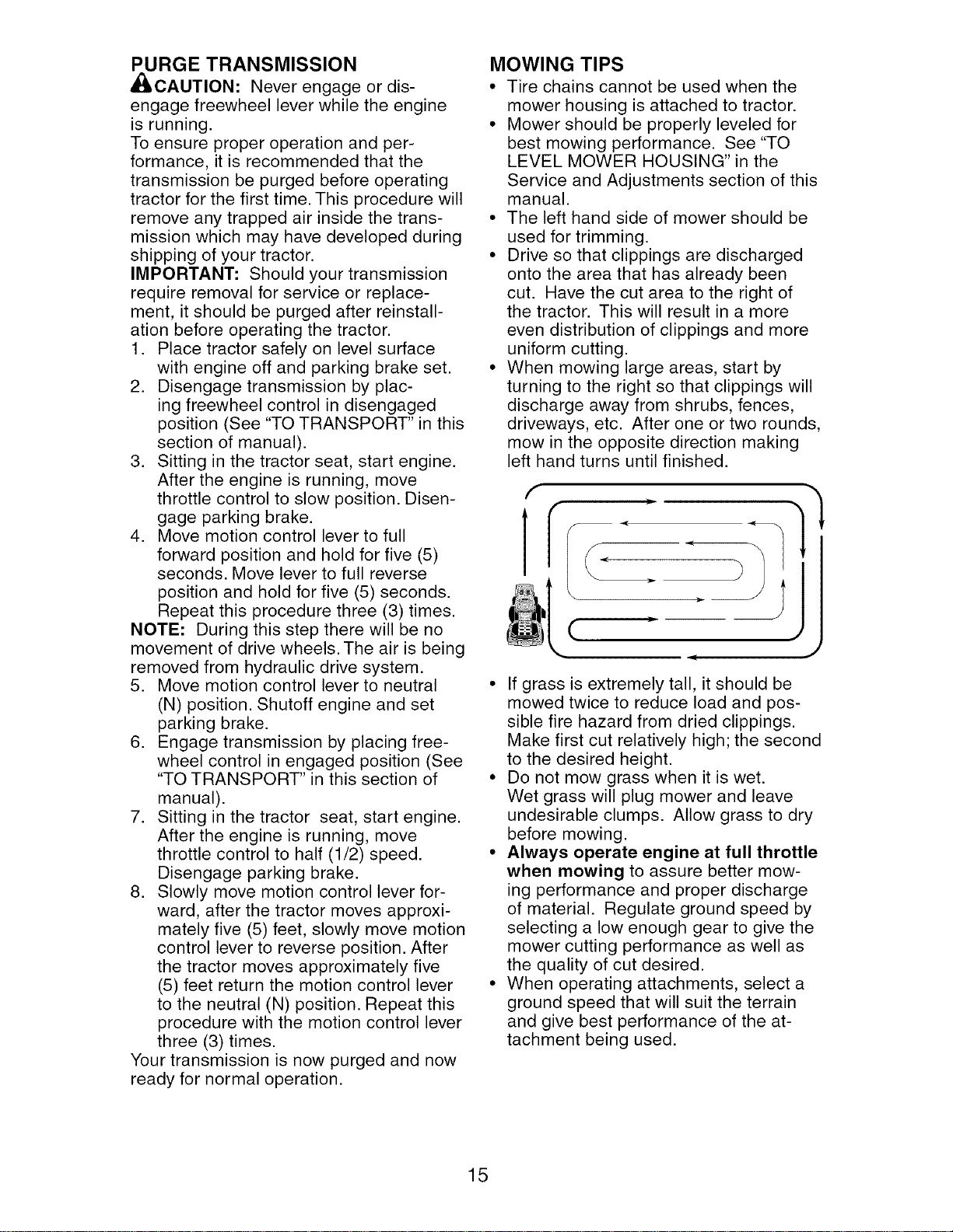
• When mowing large areas, start by
turning to the right so that clippings will
discharge away from shrubs, fences,
driveways, etc. After one or two rounds,
mow in the opposite direction making
left hand turns until finished.
J=
(
J
• If grass is extremely tall, it should be
mowed twice to reduce load and pos-
sible fire hazard from dried clippings.
Make first cut relatively high; the second
to the desired height.
• Do not mow grass when it is wet.
Wet grass will plug mower and leave
undesirable clumps. Allow grass to dry
before mowing.
• Always operate engine at full throttle
when mowing to assure better mow-
ing performance and proper discharge
of material. Regulate ground speed by
selecting a low enough gear to give the
mower cutting performance as well as
the quality of cut desired.
• When operating attachments, select a
ground speed that will suit the terrain
and give best performance of the at-
tachment being used.
15
MA,.TE.A.OESO.EOULE
AS YOU COMPLETE
RE OL RSERV,CE VICED ATES
Chh__ Biraek; iOsPe_;i ° n _
Check Operator Presence and
T ROS Systems If
R Check for Loose Fasteners tf I_s I_
A Sharpen/Replace Mower Blades 1_3
TC Lubrication Chart If If
0 Check Battery Level 1_4
R Clean Battery and Terminals If
Check Transaxle Cooling
Check V-Belts If
Check Engine Oil Level I_ If
Change Engine Oil (with oil filter) 1_1,2 I_
i= Change Engine Oil (without oil filter) I_1,_ I_
N Clean Air Filter _llf 2
G Clean Air Screen _111_2
Inspect Muffler/Spark Arrester I_
E Replace Oil Filter (If equipped) _1_,2
Clean Engine Cooling Fins If 2
Replace Spark Plug If I_
Replace Air Filter Paper Cartridge V'2
Replace Fuel Filter
1 - Change more often when operating under a heavy load or
in high ambient temperatures.
2 - Service more often when operating in dirty or dusty conditions.
3 - Replace blades more often when mowing in sandy soil.
4 - Not required if equipped with maintenance-free battery.
5 - Tighten front axle pivot bolt to 35 ft.-Ibs, maximum.
Do not overtighten.
GENERAL RECOMMENDATIONS
The warranty on this tractor does not
cover items that have been subjected to
operator abuse or negligence. To receive
full value from the warranty, operator
must maintain tractor as instructed in this
manual.
Some adjustments will need to be made
periodically to properly maintain your
tractor.
At least once a season, check to see if
you should make any of the adjustments
described in the Service and Adjustments
section of this manual.
• At least once a year you should replace
the spark plug, clean or replace air filter,
and check blades and belts for wear.
A new spark plug and clean air filter
assure proper air-fuel mixture and help
your engine run better and last longer.
BEFORE EACH USE
1. Check engine oil level.
2. Check brake operation.
3. Check tire pressure.
4. Check operator presence and
ROS systems for proper operation.
5. Check for loose fasteners.
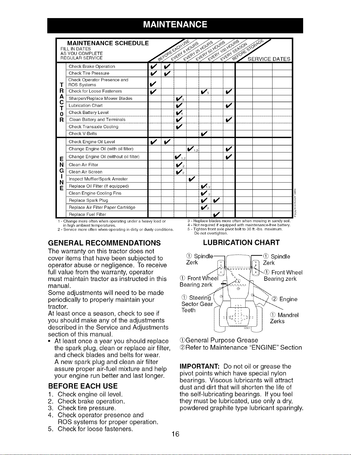
LUBRICATION CHART
S_ Spindle
Zerk Zerk
Front Wheel
Bearing zerk
Front Wheel
Bearing zerk
Engine
Sector Gear
Teeth
Mandrel
Zerks
(l_bGeneral Purpose Grease
(2bRefer to Maintenance "ENGINE" Section
IMPORTANT: Do not oil or grease the
pivot points which have special nylon
bearings. Viscous lubricants will attract
dust and dirt that will shorten the life of
the self-lubricating bearings. If you feel
they must be lubricated, use only a dry,
powdered graphite type lubricant sparingly.
16
TRACTOR
Always observe safety rules when per-
forming any maintenance.
BRAKE OPERATION
If tractor requires more than five (5) feet to
stop at highest speed in highest gear on a
level, dry concrete or paved surface, then
brake must be checked and adjusted. (See
"TO ADJUST BRAKE" in the Service and
Adjustments section of this manual).
TIRES
• Maintain proper air pressure in all tires
(See "PRODUCT SPECIFICATIONS"
section of this manual).
• Keep tires free of gasoline, oil, or insect
control chemicals which can harm rub-
ber.
• Avoid stumps, stones, deep ruts, sharp
objects and other hazards that may
cause tire damage.
NOTE: To seal tire punctures and prevent
flat tires due to slow leaks, tire sealant
may be purchased from your local parts
dealer. Tire sealant also prevents tire dry
rot and corrosion.
OPERATOR PRESENCE SYSTEM AND
REVERSE OPERATION SYSTEM (ROS)
Be sure operator presence and reverse
operation systems are working properly. If
your tractor does not function as de-
scribed, repair the problem immediately.
• The engine should not start unless the
brake pedal is fully depressed, and the
attachment clutch control is in the disen-
gaged position.
CHECK OPERATOR PRESENCE
SYSTEM
• When the engine is running, any at-
tempt by the operator to leave the seat
without first setting the parking brake
should shut off the engine.
• When the engine is running and the
attachment clutch is engaged, any at-
tempt by the operator to leave the seat
should shut off the engine.
• The attachment clutch should never op-
erate unless the operator is in the seat.
ROS "ON" Position Engine "ON" Position
(Normal Operating)
CHECK REVERSE OPERATION (ROS)
SYSTEM
• When the engine is running with the
ignition switch in the engine "ON" posi-
tion and the attachment clutch engaged,
any attempt by the operator to shift into
reverse should shut off the engine.
• When the engine is running with the
ignition switch in the ROS "ON" position
and the attachment clutch engaged,
any attempt by the operator to shift into
reverse should NOT shut off the engine.
BLADE CARE
For best results mower blades must be
kept sharp. Replace bent or damaged
blades.
_, CAUTION: Use only a replacement
blade approved by the manufacturer of
your tractor. Using a blade not approved
by the manufacturer of your tractor is
hazardous, could damage your tractor and
void your warranty.
BLADE REMOVAL
1. Raise mower to highest position to al-
low access to blades.
NOTE: Protect your hands with gloves
and/or wrap blade with heavy cloth.
2. Remove blade bolt by turning counter-
clockwise.
3. Install new or resharpened blade with
stamped "THIS SIDE UP" facing deck
and mandrel assembly.
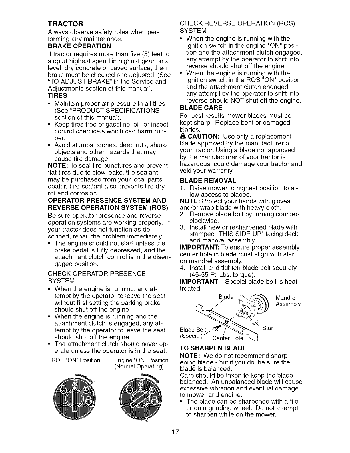
IMPORTANT: To ensure proper assembly,
center hole in blade must align with star
on mandrel assembly.
4. Install and tighten blade bolt securely
(45-55 Ft. Lbs. torque).
IMPORTANT: Special blade bolt is heat
treated.
___ _ Mandrel
)) Assembly
Blade Bolt/J_ _ _'_'_"Star
(Special)" Cen{er Hole"_
TO SHARPEN BLADE
NOTE: We do not recommend sharp-
ening blade - but if you do, be sure the
blade is balanced.
Care should be taken to keep the blade
balanced. An unbalanced blade will cause
excessive vibration and eventual damage
to mower and engine.
• The blade can be sharpened with a file
or on a grinding wheel. Do not attempt
to sharpen while on the mower.
17
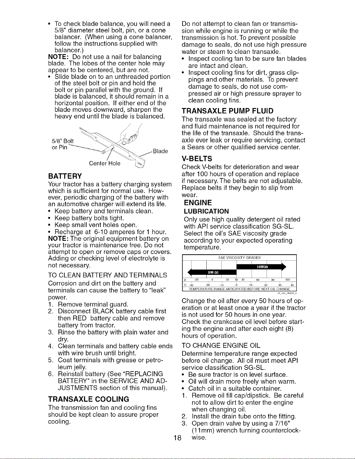
• To check blade balance, you will need a
5/8" diameter steel bolt, pin, or a cone
balancer. (When using a cone balancer,
follow the instructions supplied with
balancer.)
NOTE: Do not use a nail for balancing
blade. The lobes of the center hole may
appear to be centered, but are not.
• Slide blade on to an unthreaded portion
of the steel bolt or pin and hold the
bolt or pin parallel with the ground. If
blade is balanced, it should remain in a
horizontal position. If either end of the
blade moves downward, sharpen the
heavy end until the blade is balanced.
/
/
/,
5/8" Bolt
or Pin
Center Hole
BATTERY
Your tractor has a battery charging system
which is sufficient for normal use. How-
ever, periodic charging of the battery with
an automotive charger will extend its life.
• Keep battery and terminals clean.
• Keep battery bolts tight.
• Keep small vent holes open.
• Recharge at 6-10 amperes for 1 hour.
NOTE: The original equipment battery on
your tractor is maintenance free. Do not
attempt to open or remove caps or covers.
Adding or checking level of electrolyte is
not necessary.
TO CLEAN BATTERY AND TERMINALS
Corrosion and dirt on the battery and
terminals can cause the battery to "leak"
power.
1. Remove terminal guard.
2. Disconnect BLACK battery cable first
then RED battery cable and remove
battery from tractor.
3. Rinse the battery with plain water and
dry.
4. Clean terminals and battery cable ends
with wire brush until bright.
5. Coat terminals with grease or petro-
leum jelly.
6. Reinstall battery (See "REPLACING
BATTERY" in the SERVICE AND AD-
JUSTMENTS section of this manual).
TRANSAXLE COOLING
The transmission fan and cooling fins
should be kept clean to assure proper
cooling.
Do not attempt to clean fan or transmis-
sion while engine is running or while the
transmission is hot. To prevent possible
damage to seals, do not use high pressure
water or steam to clean transaxle.
• Inspect cooling fan to be sure fan blades
are intact and clean.
• Inspect cooling fins for dirt, grass clip-
pings and other materials. To prevent
damage to seals, do not use com-
pressed air or high pressure sprayer to
clean cooling fins.
TRANSAXLE PUMP FLUID
The transaxle was sealed at the factory
and fluid maintenance is not required for
the life of the transaxle. Should the trans-
axle ever leak or require servicing, contact
a Sears or other qualified service center.
V-BELTS
Check V-belts for deterioration and wear
after 100 hours of operation and replace
if necessary. The belts are not adjustable.
Replace belts if they begin to slip from
wear.
ENGINE
LUBRICATION
Only use high quality detergent oil rated
with API service classification SG-SL.
Select the oil's SAE viscosity grade
according to your expected operating
temperature.
SAE VISCOSITY GRADES
F
TEMPERATURE RANGE ANTICIPATED BEFORE NEXT OIL CHANGE
oilviscchart4 e
Change the oil after every 50 hours of op-
eration or at least once a year if the tractor
is not used for 50 hours in one year.
Check the crankcase oil level before start-
ing the engine and after each eight (8)
hours of operation.
TO CHANGE ENGINE OIL
Determine temperature range expected
before oil change. All oil must meet API
service classification SG-SL.
• Be sure tractor is on level surface.
• Oil will drain more freely when warm.
• Catch oil in a suitable container.
1. Remove oil fill cap/dipstick. Be careful
not to allow dirt to enter the engine
when changing oil.
2. Install the drain tube onto the fitting.
3. Open drain valve by using a 7/16"
(11 mm) wrench turning counterclock-
wise.
18
Oil Drain Valve
To Open
To Close
Drain Tube
4. After oil has drained completely, close
the drain valve turning clockwise. Use
the 7/16" (11 mm) wrench to apply
a small amount of torque to keep it
closed. Do not over tighten.
5. Remove the drain tube and store in a
safe place.
6. Refill engine with oil through oil fill dip-
stick tube. Pour slowly. Do not overfill.
For approximate capacity see "PROD-
UCT SPECIFICATIONS" section of this
manual.
7. Use gauge on oil fill cap/dipstick for
checking level. Insert dipstick into
the tube and rest the oil fill cap on the
tube. Do not thread the cap onto the
tube when taking reading. Keep oil
at "FULl" line on dipstick. Tighten cap
onto the tube securely when finished.
ENGINE OIL FILTER
Replace the engine oil filter every season
or every other oil change if the tractor is
used more than 100 hours in one year.
AIR FILTER
Your engine will not run properly using a
dirty air filter. Clean the foam pre-cleaner
after every 25 hours of operation or every
season. Service paper cartridge every
100 hours of operation or every season,
whichever occurs first.
Service air cleaner more often under dusty
conditions.
1. Loosen knob and remove cover.
TO SERVICE PRE-CLEANER
2. Slide foam pre-cleaner off cartridge.
3. Wash it in liquid detergent and water.
4. Squeeze it dry in a clean cloth. Allow it
to dry.
5. Saturate it in engine oil. Wrap it in
clean, absorbent cloth and squeeze to
remove excess oil.
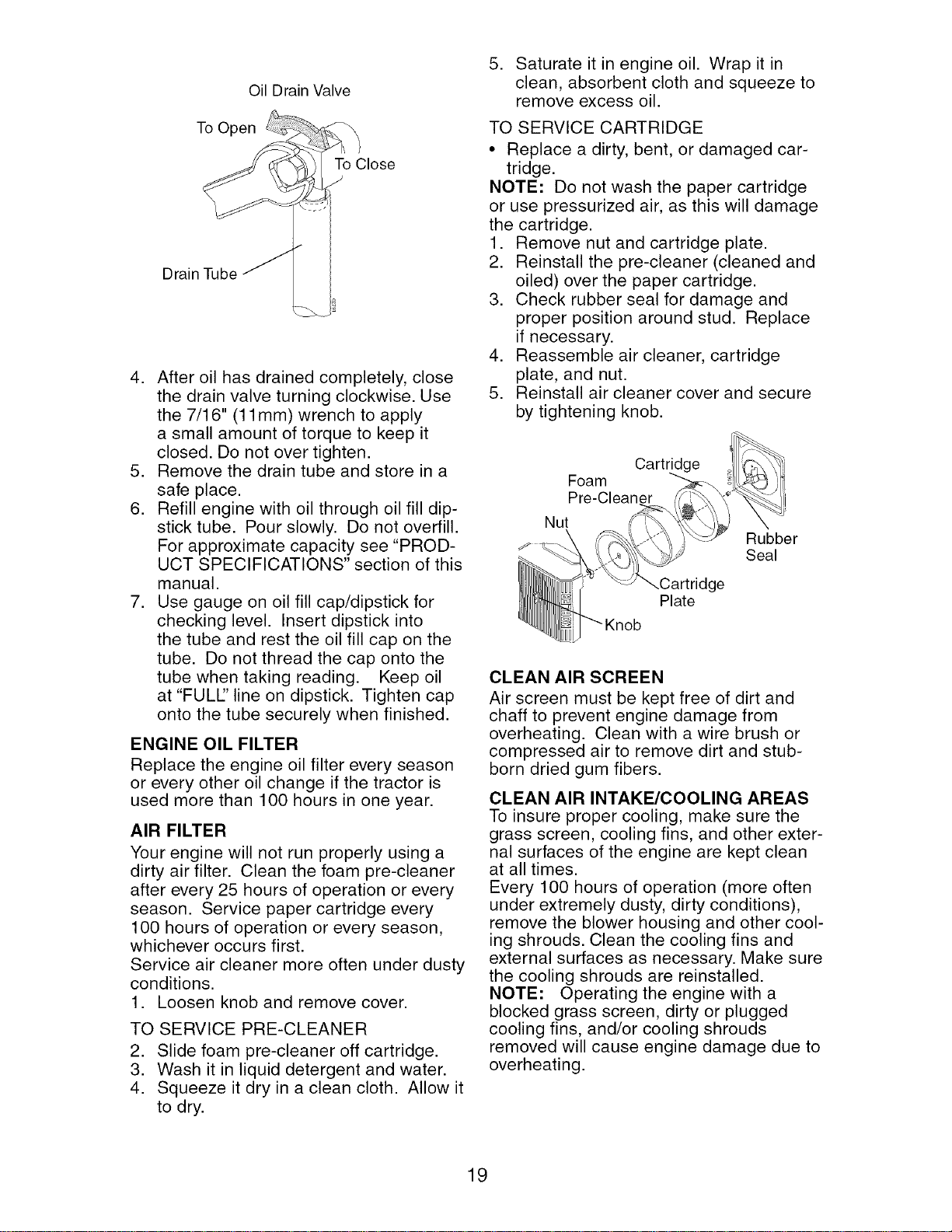
TO SERVICE CARTRIDGE
• Replace a dirty, bent, or damaged car-
tridge.
NOTE: Do not wash the paper cartridge
or use pressurized air, as this will damage
the cartridge.
1. Remove nut and cartridge plate.
2. Reinstall the pre-cleaner (cleaned and
oiled) over the paper cartridge.
3. Check rubber seal for damage and
proper position around stud. Replace
if necessary.
4. Reassemble air cleaner, cartridge
plate, and nut.
5. Reinstall air cleaner cover and secure
by tightening knob.
Cartridge
Foam
Pre-Cleaner
Nut
--.Cartridge
Plate
Rubber
Seal
CLEAN AIR SCREEN
Air screen must be kept free of dirt and
chaff to prevent engine damage from
overheating. Clean with a wire brush or
compressed air to remove dirt and stub-
born dried gum fibers.
CLEAN AIR INTAKE/COOLING AREAS
To insure proper cooling, make sure the
grass screen, cooling fins, and other exter-
nal surfaces of the engine are kept clean
at all times.
Every 100 hours of operation (more often
under extremely dusty, dirty conditions),
remove the blower housing and other cool-
ing shrouds. Clean the cooling fins and
external surfaces as necessary. Make sure
the cooling shrouds are reinstalled.
NOTE: Operating the engine with a
blocked grass screen, dirty or plugged
cooling fins, and/or cooling shrouds
removed will cause engine damage due to
overheating.
19
MUFFLER
Inspect and replace corroded muffler and
spark arrester (if equipped) as it could cre-
ate a fire hazard and/or damage.
SPARK PLUG(S)
Replace spark plug(s) at the beginning
of each mowing season or after every
100 hours of operation, whichever occurs
first. Spark plug type and gap setting are
shown in "PRODUCT SPECIFICATIONS"
section of this manual.
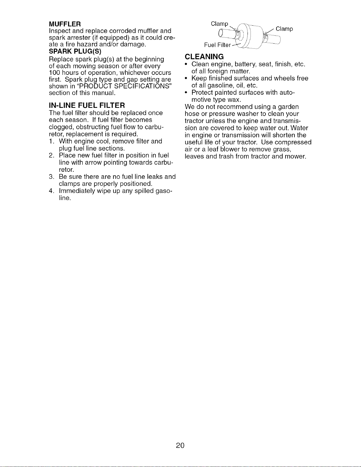
IN-LINE FUEL FILTER
The fuel filter should be replaced once
each season. If fuel filter becomes
clogged, obstructing fuel flow to carbu-
retor, replacement is required.
1. With engine cool, remove filter and
plug fuel line sections.
2. Place new fuel filter in position in fuel
line with arrow pointing towards carbu-
retor.
3. Be sure there are no fuel line leaks and
clamps are properly positioned.
4. Immediately wipe up any spilled gaso-
line.
Clamp
Clamp
Fuel Filter-
CLEANING
• Clean engine, battery, seat, finish, etc.
of all foreign matter.
• Keep finished surfaces and wheels free
of all gasoline, oil, etc.
• Protect painted surfaces with auto-
motive type wax.
We do not recommend using a garden
hose or pressure washer to clean your
tractor unless the engine and transmis-
sion are covered to keep water out. Water
in engine or transmission will shorten the
useful life of your tractor. Use compressed
air or a leaf blower to remove grass,
leaves and trash from tractor and mower.
20

WARNING: TO AVOID SERIOUS INJURY, BEFORE PERFORMING ANY SER-
VICE OR ADJUSTMENTS:
1. Depress brake pedal fully and set parking brake.
2. Place attachment clutch in "DISENGAGED" position.
3. Turn ignition key to "STOP" and remove key.
4. Make sure the blades and all moving parts have completely stopped.
5. Disconnect spark plug wire from spark plug and place wire where it cannot
come in contact with plug.
TRACTOR
TO REMOVE MOWER
1. Place attachment clutch in "DISEN-
GAGED" position.
2. If equipped, turn height adjustment
knob to lowest setting.
3. Lower mower to its lowest position.
4. Disengage belt tension rod from lock
bracket.
_, CAUTION: Rod is spring loaded. Have
a tight grip on rod and release slowly.
5. Remove retainer spring holding
anti-swaybar to chassis bracket and
disengage anti-sway bar from bracket.
6. Remove four retainer springs from front
plate assembly and remove plate.
7. Remove retainer springs from suspen-
sion arms at deck and disengage arms
from deck.
8. Raise attachment lift to its highest posi-
tion.
9. Slide mower forward and remove belt
from electric clutch pulley.
10. Slide mower out from under right side
of tractor.
TO INSTALL MOWER
Be sure tractor is on level surface and
mower suspension arms are raised with
attachment lift control. Engage parking
brake.
1. Swing anti-sway bar to left side of
mower deck.
2. Slide mower under tractor with deflec-
tor shield to right side of tractor.
IMPORTANT: Check belt for proper rout-
ing in all mower pulley grooves.
3. If equipped, turn height adjustment
knob counterclockwise until it stops.
4. Lower mower linkage with attachment
lift control.
5. Be sure belt tension rod is in disen-
gaged position.
6. Install belt into electric clutch pulley
groove.
7. Place the suspension arms on outward
pointing deck pins. Retain with double
loop retainer spring with loops up as
shown.
8. Install front plate assembly to tractor
suspension brackets and retain with
single loop retainer springs as shown.
Lock Bracket
Belt Tension Rod _;
(Disengaged _.._.--_,;'
Position) _
Chassis
Bmcket
Front Mower
Bracket Electric Clutch Double Loop
Pulley Retainer Springs
Plate
Assembly
Retainer
Spring
Anti-Sway
Bar
USE PLIERS FOR
RETAINER SPRINGS
Suspension Arm
Double Loop
Retainer Springs
(Outward pointing
deck pins)
1 02565
Single Loop
Retainer Springs
Flanged Pins
Front Mower
Bracket
Deflector Shield
9. Position front plate assembly between
front mower brackets. Raise deck and
plate assembly to align holes and
insert flanged pins. Secure pins with
double loop retainer springs between
the plate assembly and mower brack-
ets.
NOTE: To assist in locating hole in flanged
pin, the hole in pin is inline with notch on
head of pin. If necessary, move mower
side-to-side to give space between plate
and mower brackets.
IMPORTANT: Check belt for proper rout-
ing in all mower pulley grooves.
10. Engage belt tension rod by pushing rod
into locking bracket.
CAUTION: Belt tension rod is spring
loaded. Have a tight grip on rod and en-
gage slowly.
11. Connect anti-sway bar to chassis
bracket under left footrest and retain
with double loop retainer spring.
12. If equipped, turn height adjustment
knob clockwise to remove slack from
mower suspension.
13. Raise deck to highest position.
TO LEVEL MOWER HOUSING
Adjust the mower while tractor is parked
on level ground or driveway. Make sure
tires are properly inflated (See "PROD-
UCT SPECIFICATIONS" section of this
manual). If tires are over or underinflated,
you will not properly adjust your mower.
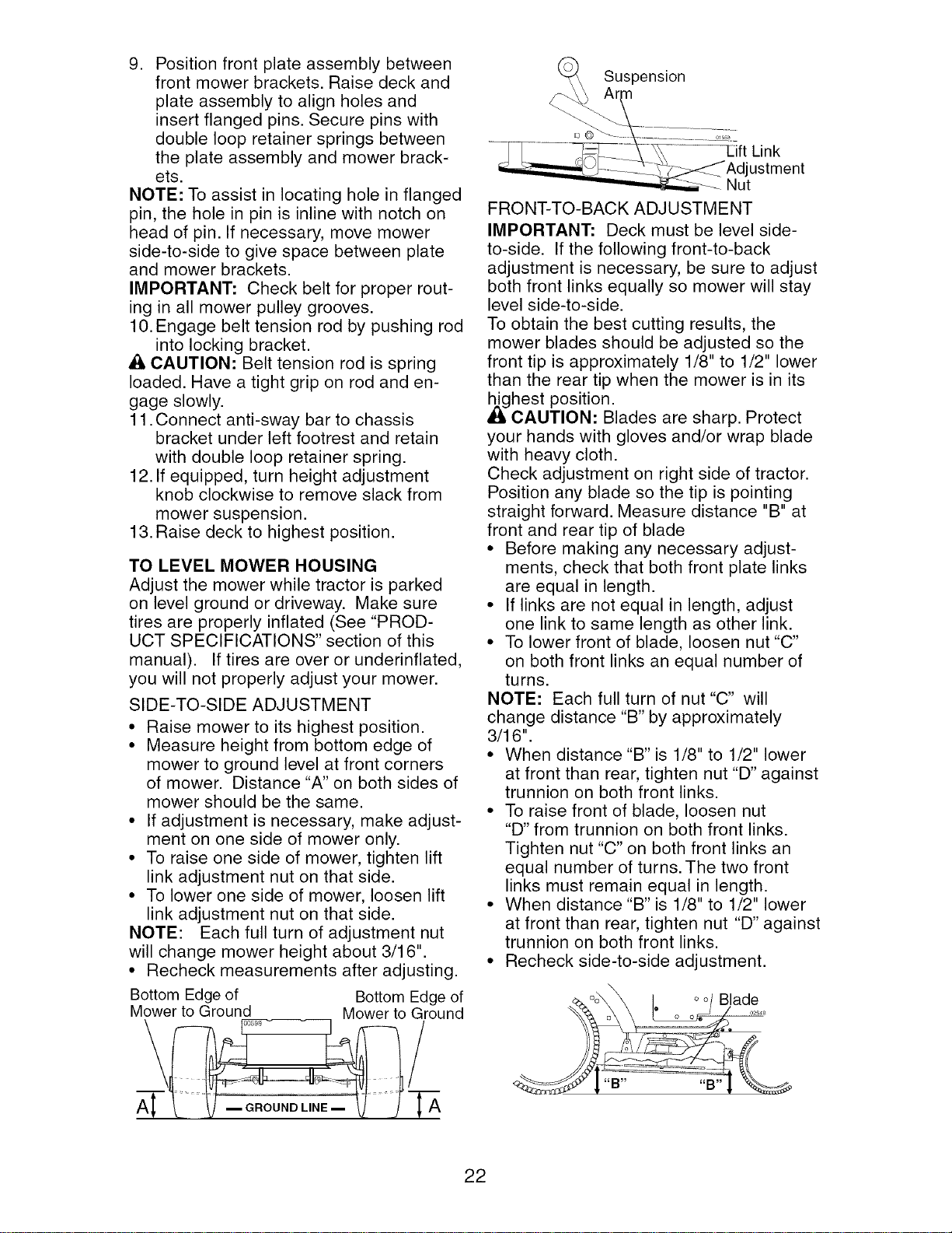
SIDE-TO-SIDE ADJUSTMENT
• Raise mower to its highest position.
• Measure height from bottom edge of
mower to ground level at front corners
of mower. Distance "A" on both sides of
mower should be the same.
• If adjustment is necessary, make adjust-
ment on one side of mower only.
• To raise one side of mower, tighten lift
link adjustment nut on that side.
• To lower one side of mower, loosen lift
link adjustment nut on that side.
NOTE: Each full turn of adjustment nut
will change mower height about 3/16".
• Recheck measurements after adjusting.
Bottom Edge of Bottom Edge of
Mower to Ground Mower to Ground
(_A Suspensi°n
i.,ink
Adjustment
........_ Nut
FRONT-TO-BACK ADJUSTMENT
IMPORTANT: Deck must be level side-
to-side. If the following front-to-back
adjustment is necessary, be sure to adjust
both front links equally so mower will stay
level side-to-side.
To obtain the best cutting results, the
mower blades should be adjusted so the
front tip is approximately 1/8" to 1/2" lower
than the rear tip when the mower is in its
,_ghest position.
CAUTION: Blades are sharp. Protect
your hands with gloves and/or wrap blade
with heavy cloth.
Check adjustment on right side of tractor.
Position any blade so the tip is pointing
straight forward. Measure distance "B" at
front and rear tip of blade
• Before making any necessary adjust-
ments, check that both front plate links
are equal in length.
• If links are not equal in length, adjust
one link to same length as other link.
• To lower front of blade, loosen nut "C"
on both front links an equal number of
turns.
NOTE: Each full turn of nut "C" will
change distance "B" by approximately
3/16".
• When distance "B" is 1/8" to 1/2" lower
at front than rear, tighten nut "D" against
trunnion on both front links.
• To raise front of blade, loosen nut
"D" from trunnion on both front links.
Tighten nut "C" on both front links an
equal number of turns. The two front
links must remain equal in length.
• When distance "B" is 1/8" to 1/2" lower
at front than rear, tighten nut "D" against
trunnion on both front links.
• Recheck side-to-side adjustment.
q_.°o\_ I oo/Blade
22
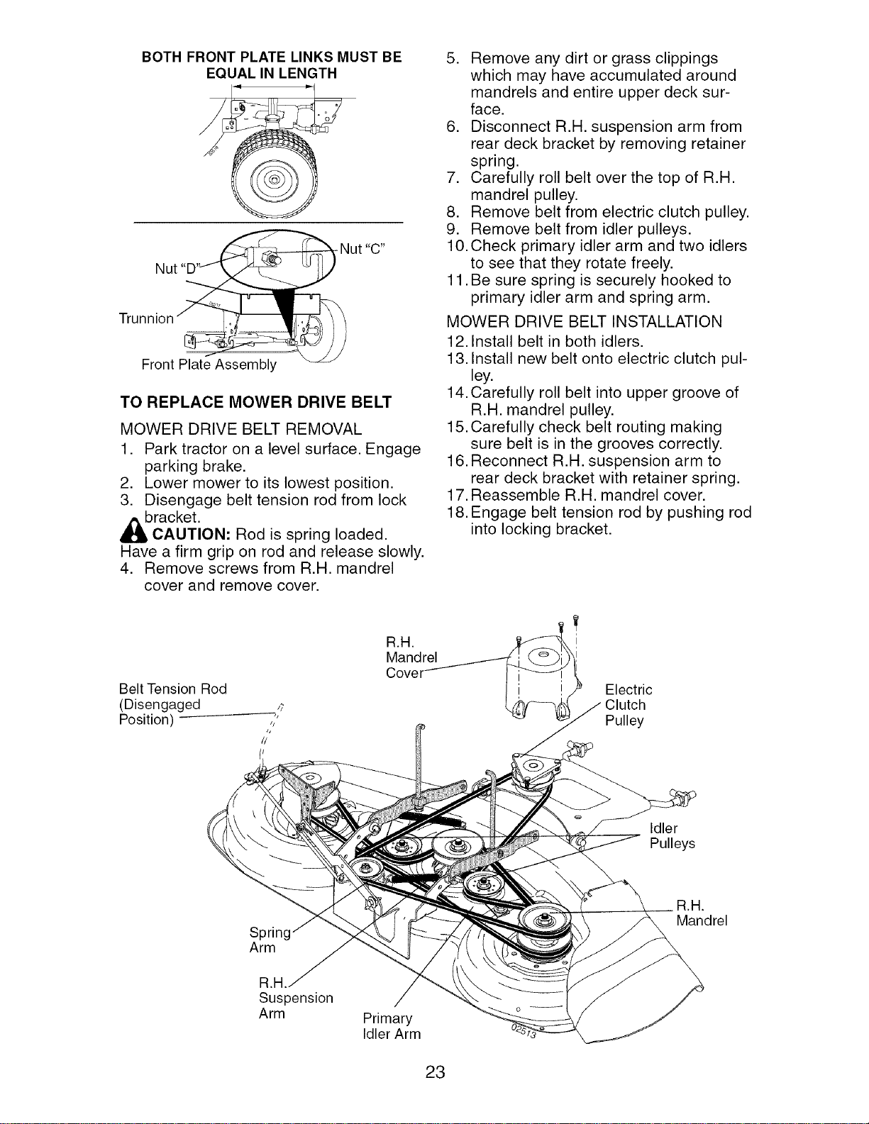
BOTH FRONT PLATE LINKS MUST BE
EQUAL IN LENGTH
Nut
Trunnion
/
Front Plate Assembly
TO REPLACE MOWER DRIVE BELT
MOWER DRIVE BELT REMOVAL
1. Park tractor on a level surface. Engage
parking brake.
2. Lower mower to its lowest position.
3. Disengage belt tension rod from lock
bracket.
CAUTION: Rod is spring loaded.
Have a firm grip on rod and release slowly.
4. Remove screws from R.H. mandrel
cover and remove cover.
R,a.
Mandrel
5. Remove any dirt or grass clippings
which may have accumulated around
mandrels and entire upper deck sur-
face.
6. Disconnect R.H. suspension arm from
rear deck bracket by removing retainer
spring.
7. Carefully roll belt over the top of R.H.
mandrel pulley.
8. Remove belt from electric clutch pulley.
9. Remove belt from idler pulleys.
10. Check primary idler arm and two idlers
to see that they rotate freely.
11. Be sure spring is securely hooked to
primary idler arm and spring arm.
MOWER DRIVE BELT INSTALLATION
12. Install belt in both idlers.
13. Install new belt onto electric clutch pul-
ley.
14. Carefully roll belt into upper groove of
R.H. mandrel pulley.
15. Carefully check belt routing making
sure belt is in the grooves correctly.
16. Reconnect R.H. suspension arm to
rear deck bracket with retainer spring.
17. Reassemble R.H. mandrel cover.
18. Engage belt tension rod by pushing rod
into locking bracket.
I
Electric
Clutch
Pulley
Idler
Pulleys
Spring
Arm
R,a.
Mandrel
Suspension
Arm
Primary
Idler Arm
23
TO REPLACE MOWER BLADE (SEC-
ONDARY) DRIVE BELT
Park the tractor on level surface. Engage
parking brake.
1. Remove mower (See "TO REMOVE
MOWER" in this section of manual).
2. Remove screws from R.H. and L.H.
mandrel covers and remove covers.
REMOVE MOWER DRIVE BELT
(Refer to "TO REMOVE MOWER DRIVE
BELT" illustration in this section of
manual).
3. Carefully roll belt over the top of R.H.
mandrel pulley.
4. Remove belt from idler pulleys.
5. Check primary idler arm and two idlers
to see that they rotate freely.
6. Be sure spring is securely hooked to
primary idler arm and spring arm.
REMOVE MOWER BLADE
(SECONDARY) DRIVE BELT
7. Carefully roll belt off L.H. mandrel pul-
ley.
8. Remove belt from center mandrel
pulley, idler pulley, and R.H. mandrel
pulley.
9. Remove any dirt or grass which may
have accumulated around mandrels
and entire upper deck surface.
10. Check secondary idler arm and idler
pulley to see that they rotate freely.
11. Be sure spring is hooked in secondary
idler arm and secondary spring arm.
INSTALL NEW MOWER BLADE
(SECONDARY) DRIVE BELT
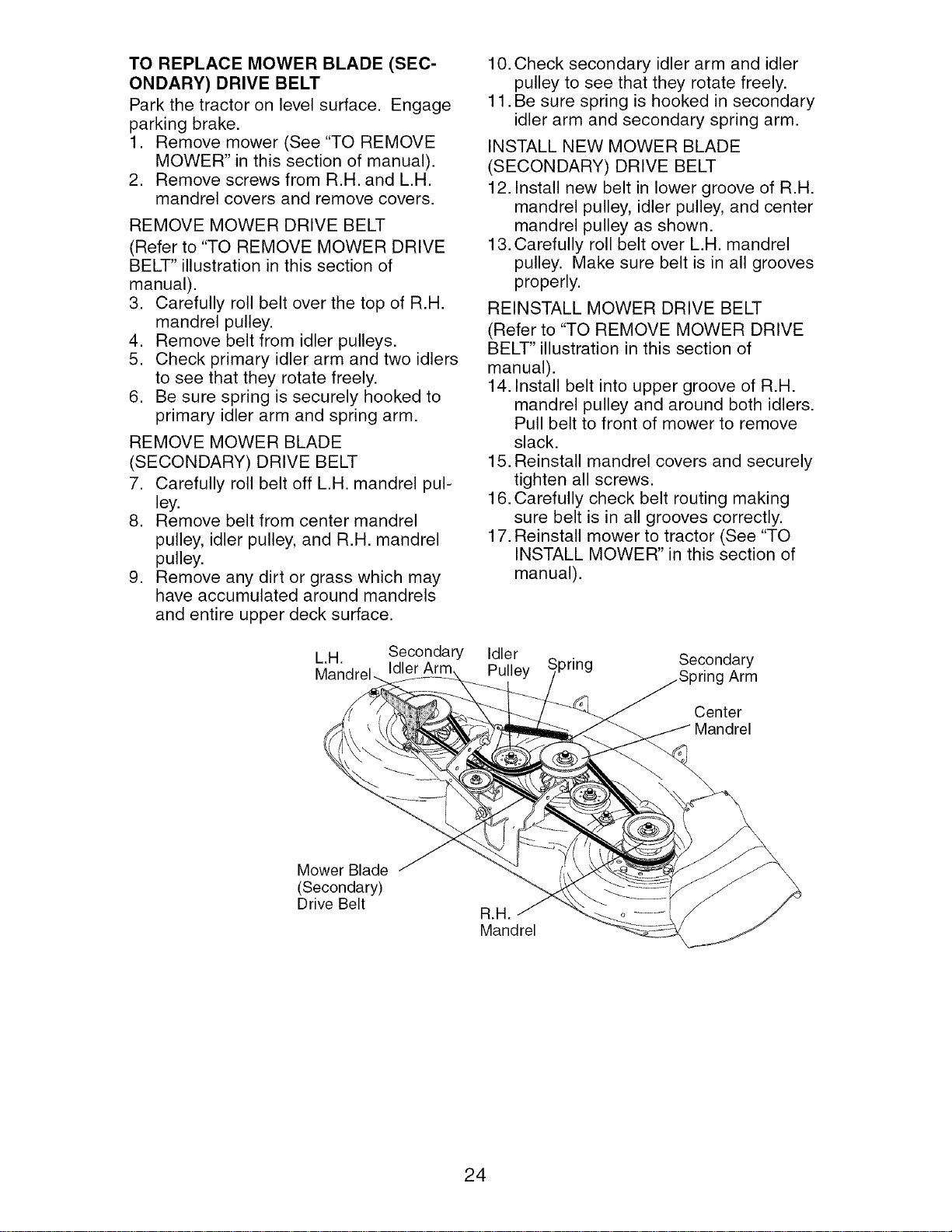
12. Install new belt in lower groove of R.H.
mandrel pulley, idler pulley, and center
mandrel pulley as shown.
13. Carefully roll belt over L.H. mandrel
pulley. Make sure belt is in all grooves
properly.
REINSTALL MOWER DRIVE BELT
(Refer to "TO REMOVE MOWER DRIVE
BELT" illustration in this section of
manual).
14. Install belt into upper groove of R.H.
mandrel pulley and around both idlers.
Pull belt to front of mower to remove
slack.
15. Reinstall mandrel covers and securely
tighten all screws.
16. Carefully check belt routing making
sure belt is in all grooves correctly.
17. Reinstall mower to tractor (See "TO
INSTALL MOWER" in this section of
manual).
L.H. Secondary Idler
Idler Arm Pulley
',pring Secondary
Arm
Center
Mandrel
Mower Blade
(Secondary)
Drive Belt
B.a.
Mandrel
24
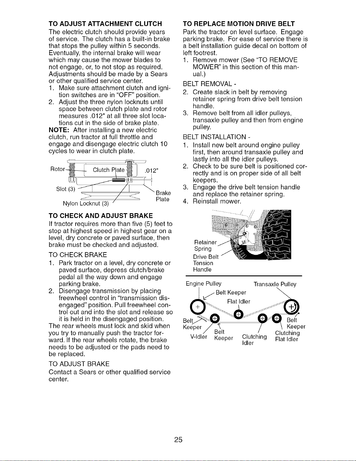
TO ADJUST ATTACHMENT CLUTCH
The electric clutch should provide years
of service. The clutch has a built-in brake
that stops the pulley within 5 seconds.
Eventually, the internal brake will wear
which may cause the mower blades to
not engage, or, to not stop as required.
Adjustments should be made by a Sears
or other qualified service center.
1. Make sure attachment clutch and igni-
tion switches are in "OFF" position.
2. Adjust the three nylon Iocknuts until
space between clutch plate and rotor
measures .012" at all three slot loca-
tions cut in the side of brake plate.
NOTE: After installing a new electric
clutch, run tractor at full throttle and
engage and disengage electric clutch 10
cycles to wear in clutch plate.
Rotor-
Slot (3)
Nylon Locknut (3)
Plate
TO CHECK AND ADJUST BRAKE
If tractor requires more than five (5) feet to
stop at highest speed in highest gear on a
level, dry concrete or paved surface, then
brake must be checked and adjusted.
TO CHECK BRAKE
1. Park tractor on a level, dry concrete or
paved surface, depress clutch/brake
pedal all the way down and engage
parking brake.
2. Disengage transmission by placing
freewheel control in "transmission dis-
engaged" position. Pull freewheel con-
trol out and into the slot and release so
it is held in the disengaged position.
The rear wheels must lock and skid when
you try to manually push the tractor for-
ward. If the rear wheels rotate, the brake
needs to be adjusted or the pads need to
be replaced.
TO ADJUST BRAKE
Contact a Sears or other qualified service
center.
TO REPLACE MOTION DRIVE BELT
Park the tractor on level surface. Engage
parking brake. For ease of service there is
a belt installation guide decal on bottom of
left footrest.
1. Remove mower (See "TO REMOVE
MOWER" in this section of this man-
ual.)
BELT REMOVAL -
2. Create slack in belt by removing
retainer spring from drive belt tension
handle.
3. Remove belt from all idler pulleys,
transaxle pulley and then from engine
pulley.
BELT INSTALLATION -
1. Install new belt around engine pulley
first, then around transaxle pulley and
lastly into all the idler pulleys.
2. Check to be sure belt is positioned cor-
rectly and is on proper side of all belt
keepers.
3. Engage the drive belt tension handle
and replace the retainer spring.
4. Reinstall mower.
Retainer
Spring
Drive Belt
Tension
Handle
Engine Pulley Transaxle Pulley
_ Belt Keeper
Flat Idler
Belt Belt
Keeper "_ Keeper
Belt Clutching
V-Idler Keeper Clutching Flat Idler
Idler
25
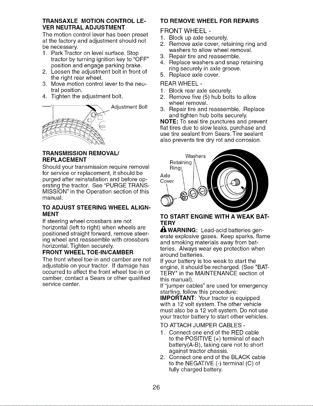
TRANSAXLE MOTION CONTROL LE-
VER NEUTRAL ADJUSTMENT
The motion control lever has been preset
at the factory and adjustment should not
be necessary.
1. Park Tractor on level surface. Stop
tractor by turning ignition key to "OFF"
position and engage parking brake.
2. Loosen the adjustment bolt in front of
the right rear wheel.
3. Move motion control lever to the neu-
tral position.
4. Tighten the adjustment bolt.
Adjustment Bolt
TRANSMISSION REMOVAL/
REPLACEMENT
Should your transmission require removal
for service or replacement, it should be
purged after reinstallation and before op-
erating the tractor. See "PURGE TRANS-
MISSION" in the Operation section of this
manual.
TO ADJUST STEERING WHEEL ALIGN-
MENT
If steering wheel crossbars are not
horizontal (left to right) when wheels are
positioned straight forward, remove steer-
ing wheel and reassemble with crossbars
horizontal. Tighten securely.
FRONT WHEEL TOE-IN/CAMBER
The front wheel toe-in and camber are not
adjustable on your tractor. If damage has
occurred to affect the front wheel toe-in or
camber, contact a Sears or other qualified
service center.
TO REMOVE WHEEL FOR REPAIRS
FRONT WHEEL -
1. Block up axle securely.
2. Remove axle cover, retaining ring and
washers to allow wheel removal.
3. Repair tire and reassemble.
4. Replace washers and snap retaining
ring securely in axle groove.
5. Replace axle cover.
REAR WHEEL -
1. Block rear axle securely.
2. Remove five (5) hub bolts to allow
wheel removal.
3. Repair tire and reassemble. Replace
and tighten hub bolts securely.
NOTE: To seal tire punctures and prevent
flat tires due to slow leaks, purchase and
use tire sealant from Sears. Tire sealant
also prevents tire dry rot and corrosion.
Washers
Retaining
Rinc
Axle
Cover
TO START ENGINE WITH A WEAK BAT-
TERY
AI_WARNING: Lead-acid batteries gen-
erate explosive gases. Keep sparks, flame
and smoking materials away from bat-
teries. Always wear eye protection when
around batteries.
If your battery is too weak to start the
engine, it should be recharged. (See "BAT-
TERY" in the MAINTENANCE section of
this manual).
If "jumper cables" are used for emergency
starting, follow this procedure:
IMPORTANT: Your tractor is equipped
with a 12 volt system. The other vehicle
must also be a 12 volt system. Do not use
your tractor battery to start other vehicles.
TO ATTACH JUMPER CABLES -
1. Connect one end of the RED cable
to the POSITIVE (+) terminal of each
battery(A-B), taking care not to short
against tractor chassis.
2. Connect one end of the BLACK cable
to the NEGATIVE (-) terminal (C) of
fully charged battery.
26
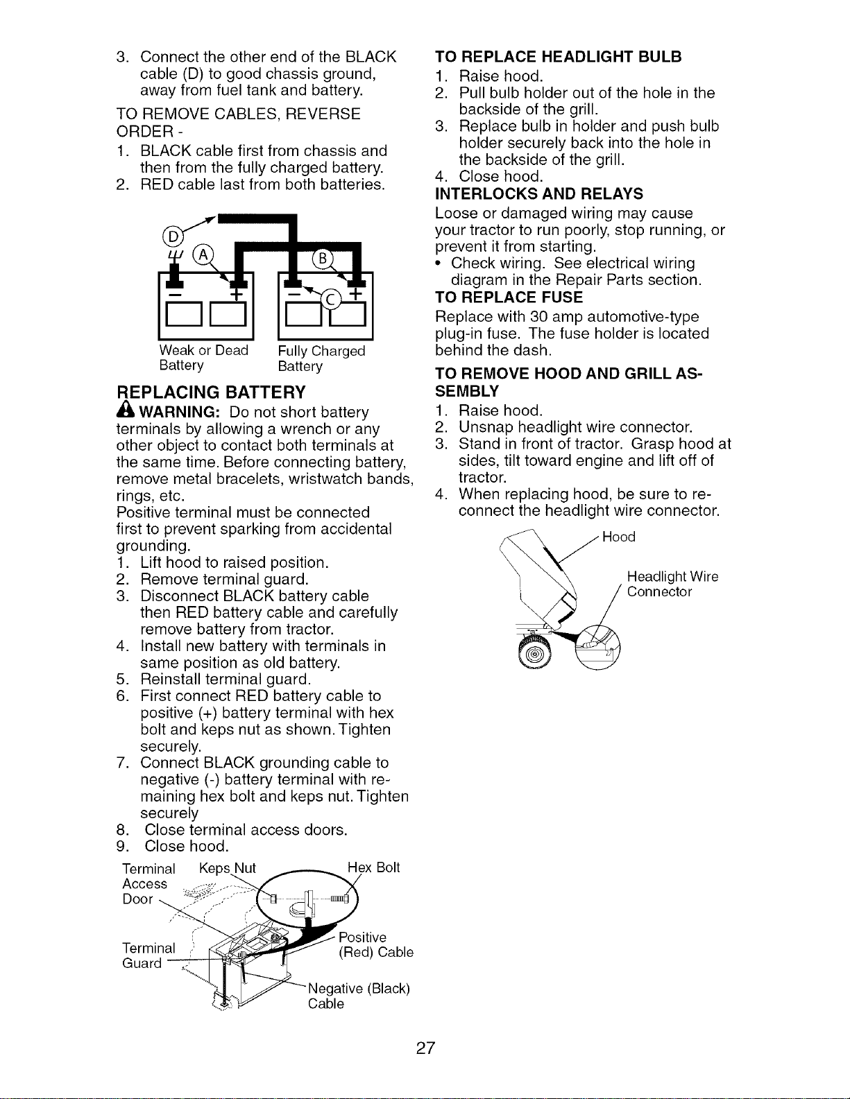
3. Connect the other end of the BLACK
cable (D) to good chassis ground,
away from fuel tank and battery.
TO REMOVE CABLES, REVERSE
ORDER -
1. BLACK cable first from chassis and
then from the fully charged battery.
2. RED cable last from both batteries.
Weak or Dead Fully Charged
Battery Battery
REPLACING BATTERY
WARNING: Do not short battery
terminals by allowing a wrench or any
other object to contact both terminals at
the same time. Before connecting battery,
remove metal bracelets, wristwatch bands,
rings, etc.
Positive terminal must be connected
first to prevent sparking from accidental
grounding.
1. Lift hood to raised position.
2. Remove terminal guard.
3. Disconnect BLACK battery cable
then RED battery cable and carefully
remove battery from tractor.
4. Install new battery with terminals in
same position as old battery.
5. Reinstall terminal guard.
6. First connect RED battery cable to
positive (+) battery terminal with hex
bolt and keps nut as shown. Tighten
securely.
7. Connect BLACK grounding cable to
negative (-) battery terminal with re-
maining hex bolt and keps nut. Tighten
securely
8. Close terminal access doors.
9. Close hood.
Terminal Keps Nut Hex Bolt
Access
Door
itive
Ter in , u rd
,=:) (Red) Cable
........ _._ -"-Negative (Black)
..... Cable
TO REPLACE HEADLIGHT BULB
1. Raise hood.
2. Pull bulb holder out of the hole in the
backside of the grill.
3. Replace bulb in holder and push bulb
holder securely back into the hole in
the backside of the grill.
4. Close hood.
INTERLOCKS AND RELAYS
Loose or damaged wiring may cause
your tractor to run poorly, stop running, or
prevent it from starting.
• Check wiring. See electrical wiring
diagram in the Repair Parts section.
TO REPLACE FUSE
Replace with 30 amp automotive-type
plug-in fuse. The fuse holder is located
behind the dash.
TO REMOVE HOOD AND GRILL AS-
SEMBLY
1. Raise hood.
2. Unsnap headlight wire connector.
3. Stand in front of tractor. Grasp hood at
sides, tilt toward engine and lift off of
tractor.
4. When replacing hood, be sure to re-
connect the headlight wire connector.
Headlight Wire
Connector
27
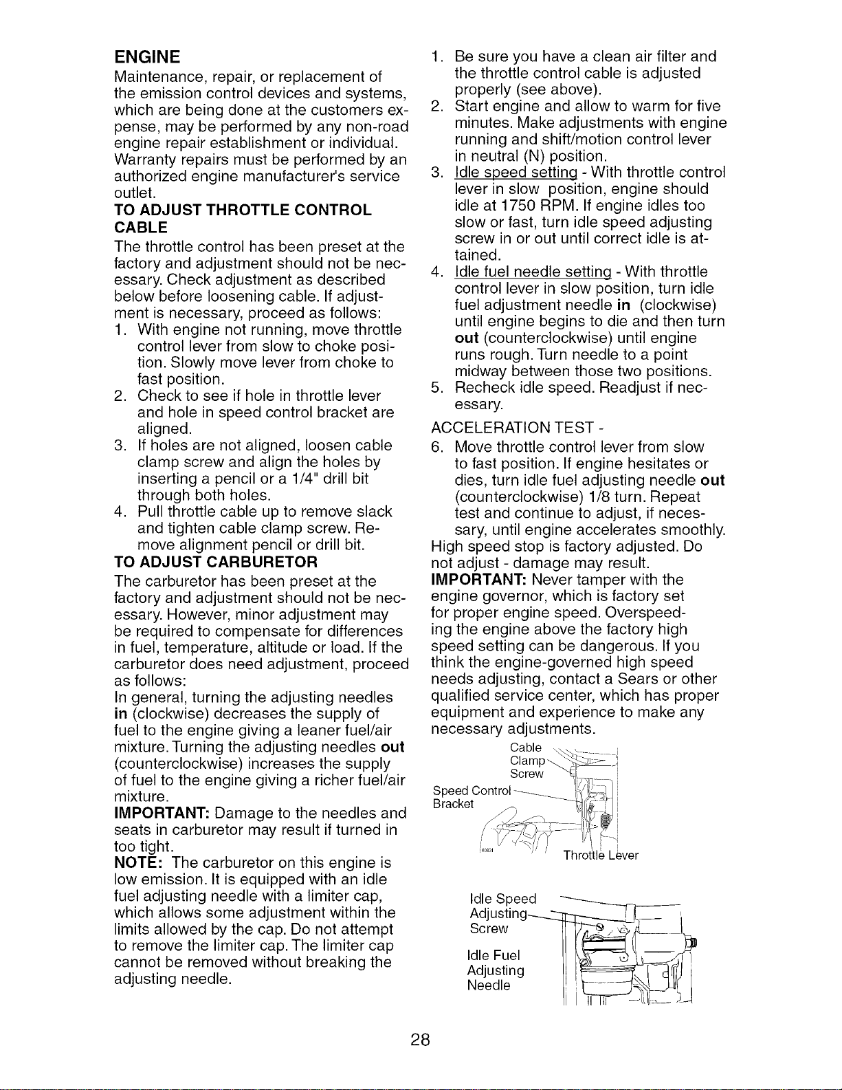
ENGINE
Maintenance, repair, or replacement of
the emission control devices and systems,
which are being done at the customers ex-
pense, may be performed by any non-road
engine repair establishment or individual.
Warranty repairs must be performed by an
authorized engine manufacturer's service
outlet.
TO ADJUST THROTTLE CONTROL
CABLE
The throttle control has been preset at the
factory and adjustment should not be nec-
essary. Check adjustment as described
below before loosening cable. If adjust-
ment is necessary, proceed as follows:
1. With engine not running, move throttle
control lever from slow to choke posi-
tion. Slowly move lever from choke to
fast position.
2. Check to see if hole in throttle lever
and hole in speed control bracket are
aligned.
3. If holes are not aligned, loosen cable
clamp screw and align the holes by
inserting a pencil or a 1/4" drill bit
through both holes.
4. Pull throttle cable up to remove slack
and tighten cable clamp screw. Re-
move alignment pencil or drill bit.
TO ADJUST CARBURETOR
The carburetor has been preset at the
factory and adjustment should not be nec-
essary. However, minor adjustment may
be required to compensate for differences
in fuel, temperature, altitude or load. If the
carburetor does need adjustment, proceed
as follows:
In general, turning the adjusting needles
in (clockwise) decreases the supply of
fuel to the engine giving a leaner fuel/air
mixture. Turning the adjusting needles out
(counterclockwise) increases the supply
of fuel to the engine giving a richer fuel/air
mixture.
IMPORTANT: Damage to the needles and
seats in carburetor may result if turned in
too tight.
NOTE: The carburetor on this engine is
low emission. It is equipped with an idle
fuel adjusting needle with a limiter cap,
which allows some adjustment within the
limits allowed by the cap. Do not attempt
to remove the limiter cap. The limiter cap
cannot be removed without breaking the
adjusting needle.
1. Be sure you have a clean air filter and
the throttle control cable is adjusted
properly (see above).
2. Start engine and allow to warm for five
minutes. Make adjustments with engine
running and shift/motion control lever
in neutral (N) position.
3. Idle speed setting - With throttle control
lever in slow position, engine should
idle at 1750 RPM. If engine idles too
slow or fast, turn idle speed adjusting
screw in or out until correct idle is at-
tained.
4. Idle fuel needle setting - With throttle
control lever in slow position, turn idle
fuel adjustment needle in (clockwise)
until engine begins to die and then turn
out (counterclockwise) until engine
runs rough. Turn needle to a point
midway between those two positions.
5. Recheck idle speed. Readjust if nec-
essary.
ACCELERATION TEST -
6. Move throttle control lever from slow
to fast position. If engine hesitates or
dies, turn idle fuel adjusting needle out
(counterclockwise) 1/8 turn. Repeat
test and continue to adjust, if neces-
sary, until engine accelerates smoothly.
High speed stop is factory adjusted. Do
not adjust - damage may result.
IMPORTANT: Never tamper with the
engine governor, which is factory set
for proper engine speed. Overspeed-
ing the engine above the factory high
speed setting can be dangerous. If you
think the engine-governed high speed
needs adjusting, contact a Sears or other
qualified service center, which has proper
equipment and experience to make any
necessary adjustments.
Cable
Clam
Screw
Speed Control
Bracket
Idle Speed
Adjusting__ I
Screw II _, _ ,d I
, ,eFue,
Adjusting II drrfJi
Needle L'"F - --_,,,_L[_I L
28
Immediately prepare your tractor for stor-
age at the end of the season or if the trac-
tor will not be used for 30 days or more.
WARNING: Never store the tractor
with gasoline in the tank inside a building
where fumes may reach an open flame
or spark. Allow the engine to cool before
storing in any enclosure.
TRACTOR
Remove mower from tractor for winter
storage. When mower is to be stored for a
period of time, clean it thoroughly, remove
all dirt, grease, leaves, etc. Store in a
clean, dry area.
1. Clean entire tractor (See "CLEANING"
in the Maintenance section of this
manual).
2. Inspect and replace belts, if necessary
(See belt replacement instructions in
the Service and Adjustments section of
this manual).
3. Lubricate as shown in the Maintenance
section of this manual.
4. Be sure that all nuts, bolts and screws
are securely fastened. Inspect moving
parts for damage, breakage and wear.
Replace if necessary.
5. Touch up all rusted or chipped paint
surfaces; sand lightly before painting.
BATTERY
• Fully charge the battery for storage.
• After a period of time in storage, battery
may require recharging.
• To help prevent corrosion and power
leakage during long periods of storage,
battery cables should be disconnected
and battery cleaned thoroughly (see "TO
CLEAN BATTERY AND TERMINALS" in
the Maintenance section of this manual).
• After cleaning, leave cables discon-
nected and place cables where they
cannot come in contact with battery
terminals.
• If battery is removed from tractor for
storage, do not store battery directly on
concrete or damp surfaces.
ENGINE
FUEL SYSTEM
IMPORTANT: It is important to prevent
gum deposites from forming in essential
fuel system parts such as carburetor, fuel
hose, or tank during storage. Also, experi-
ance indicates that alcohol blended fuels
(called gasohol or using ethanol or metha-
nol) can attract moisture which leads to
separation and formation of acids during
storage. Acidic gas can damage the fuel
system of an engine while in storage.
• Empty the fuel tank by starting the en-
gine and letting it run until the fuel lines
and carburetor are empty.
• Never use engine or carburetor cleaner
products in the fuel tank or permanent
damage may occur.
• Use fresh fuel next season.
NOTE: Fuel stabilizer is an acceptable
alternative in minimizing the formation of
fuel gum deposits during storage. Add
stabilizer to gasoline in fuel tank or stor-
age container. Always follow the mix ratio
found on stabilizer container. Run engine
at least 10 minutes after adding stabilizer
to allow the stabilizer to reach the car-
buretor. Do not empty the gas tank and
carburetor if using fuel stabilizer.
ENGINE OIL
Drain oil (with engine warm) and replace
with clean engine oil. (See "ENGINE" in
the Maintenance section of this manual).
CYLINDER(S)
1. Remove spark plug(s).
2. Pour one ounce of oil through spark
plug hole(s) into cylinder(s).
3. Turn ignition key to "START" position
for a few seconds to distribute oil.
4. Replace with new spark plug(s).
OTHER
• Do not store gasoline from one season
to another.
• Replace your gasoline can if your can
starts to rust. Rust and/or dirt in your
gasoline will cause problems.
• If possible, store your tractor indoors
and cover it to give protection from dust
and dirt.
• Cover your tractor with a suitable pro-
tective cover that does not retain mois-
ture. Do not use plastic. Plastic cannot
breathe which allows condensation to
form and will cause your tractor to rust.
IMPORTANT: Never cover tractor while
engine and exhaust areas are still warm.
29
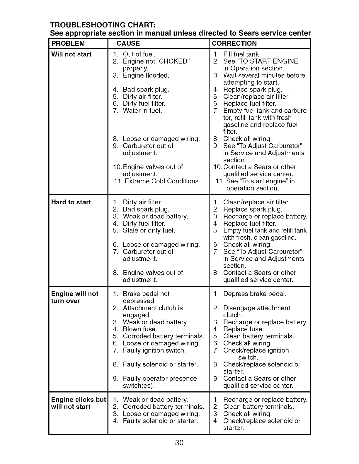
TROUBLESHOOTING CHART:
See appropriate section in manual unless directed to Sears service center
PROBLEM CAUSE CORRECTION
Will not start
Hard to start
Engine will not
turn over
1. Out of fuel.
2. Engine not "CHOKED"
properly.
3. Engine flooded.
Engine clicks but
will not start
4. Bad spark plug.
5. Dirty air filter.
6. Dirty fuel filter.
7. Water in fuel.
8. Loose or damaged wiring.
9. Carburetor out of
adjustment.
10. Engine valves out of
adjustment.
11. Extreme Cold Conditions
1. Dirty air filter.
2. Bad spark plug.
3. Weak or dead battery.
4. Dirty fuel filter.
5. Stale or dirty fuel.
6. Loose or damaged wiring.
7. Carburetor out of
adjustment.
8. Engine valves out of
adjustment.
1. Brake pedal not
depressed
2. Attachment clutch is
engaged.
3. Weak or dead battery.
4. Blown fuse.
5. Corroded battery terminals.
6. Loose or damaged wiring.
7. Faulty ignition switch.
8. Faulty solenoid or starter.
9. Faulty operator presence
switch(es).
1. Weak or dead battery.
2. Corroded battery terminals.
3. Loose or damaged wiring.
4. Faulty solenoid or starter.
1. Fill fuel tank.
2. See "TO START ENGINE"
in Operation section.
3. Wait several minutes before
attempting to start.
4. Replace spark plug.
5. Clean/replace air filter.
6. Replace fuel filter.
7. Empty fuel tank and carbure-
tor, refill tank with fresh
gasoline and replace fuel
filter.
8. Check all wiring.
9. See "To Adjust Carburetor"
in Service and Adjustments
section.
10. Contact a Sears or other
qualified service center.
11. See "To start engine" in
operation section.
1. Clean/replace air filter.
2. Replace spark plug.
3. Recharge or replace battery.
4. Replace fuel filter.
5. Empty fuel tank and refill tank
with fresh, clean gasoline.
6. Check all wiring.
7. See "To Adjust Carburetor"
in Service and Adjustments
section.
8. Contact a Sears or other
qualified service center.
1. Depress brake pedal.
2. Disengage attachment
clutch.
3. Recharge or replace battery.
4. Replace fuse.
5. Clean battery terminals.
6. Check all wiring.
7. Check/replace ignition
switch.
8. Check/replace solenoid or
starter.
9. Contact a Sears or other
qualified service center.
1. Recharge or replace battery.
2. Clean battery terminals.
3. Check all wiring.
4. Check/replace solenoid or
starter.
30
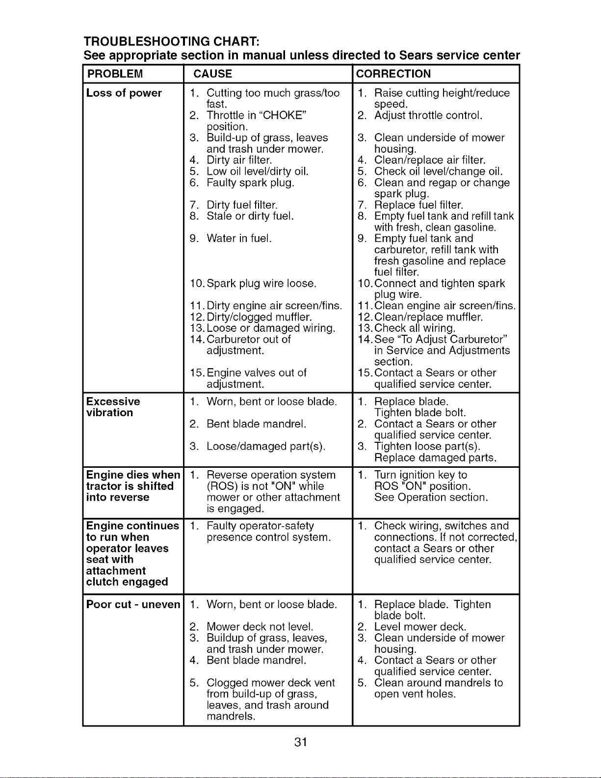
TROUBLESHOOTING CHART:
See appropriate section in manual unless directed to Sears service center
PROBLEM CAUSE CORRECTION
Loss of power 1. Cutting too much grass/too
fast.
2. Throttle in "CHOKE"
position.
3. Build-up of grass, leaves
and trash under mower.
4. Dirty air filter.
5. Low oil level/dirty oil.
6. Faulty spark plug.
7. Dirty fuel filter.
8. Stale or dirty fuel.
9. Water in fuel.
1. Raise cutting height/reduce
speed.
2. Adjust throttle control.
3. Clean underside of mower
housing.
4. Clean/replace air filter.
5. Check oil level/change oil.
6. Clean and regap or change
spark plug.
7. Replace fuel filter.
8. Empty fuel tank and refill tank
with fresh, clean gasoline.
9. Empty fuel tank and
carburetor, refill tank with
fresh gasoline and replace
fuel filter.
Excessive
vibration
Engine dies when
tractor is shifted
into reverse
Engine continues
to run when
operator leaves
seat with
attach ment
clutch engaged
Poor cut - uneven
10.Spark plug wire loose.
11. Dirty engine air screen/fins.
12. Dirty/clogged muffler.
13. Loose or damaged wiring.
14. Carburetor out of
adjustment.
15. Engine valves out of
adjustment.
1. Worn, bent or loose blade.
2. Bent blade mandrel.
3. Loose/damaged part(s).
,
Reverse operation system
(ROS) is not "ON" while
mower or other attachment
is engaged.
1. Faulty operator-safety
presence control system.
,
2.
3.
4.
5.
Worn, bent or loose blade.
Mower deck not level.
Buildup of grass, leaves,
and trash under mower.
Bent blade mandrel.
Clogged mower deck vent
from build-up of grass,
leaves, and trash around
mandrels.
10. Connect and tighten spark
plug wire.
11. Clean engine air screen/fins.
12. Clean/replace muffler.
13. Check all wiring.
14. See "To Adjust Carburetor"
in Service and Adjustments
section.
15. Contact a Sears or other
qualified service center.
1. Replace blade.
Tighten blade bolt.
2. Contact a Sears or other
qualified service center.
3. Tighten loose part(s).
Replace damaged parts.
1. Turn ignition key to
ROS "ON" position.
See Operation section.
,
Check wiring, switches and
connections. If not corrected,
contact a Sears or other
qualified service center.
1. Replace blade. Tighten
blade bolt.
2. Level mower deck.
3. Clean underside of mower
housing.
4. Contact a Sears or other
qualified service center.
5. Clean around mandrels to
open vent holes.
31
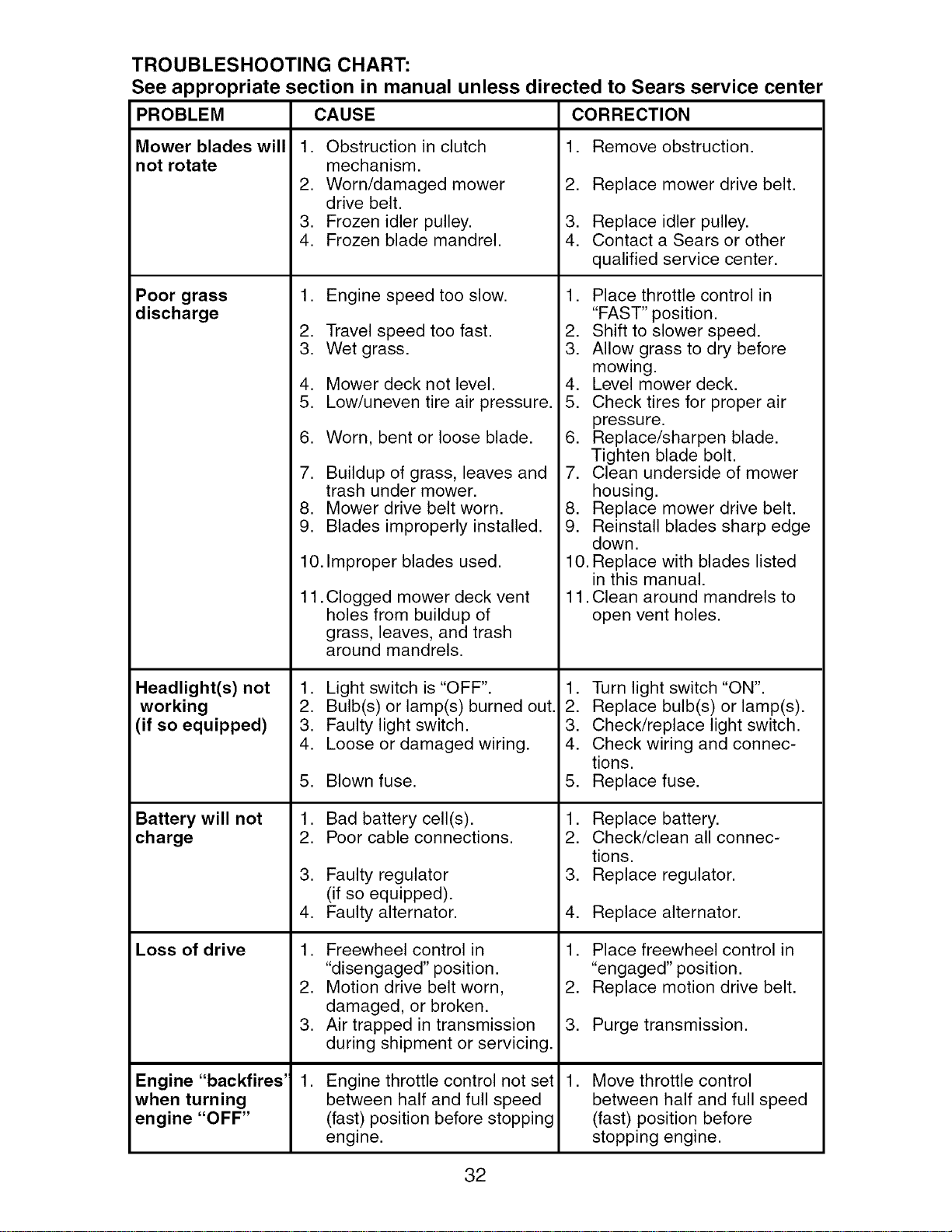
TROUBLESHOOTING CHART:
See appropriate section in manual unless directed to Sears service center
PROBLEM CAUSE
Mower blades will
not rotate
Poor grass
discharge
Headlight(s) not
working
(if so equipped)
Battery will not
charge
Loss of drive
Engine "backfires'
when turning
engine "OFF"
1. Obstruction in clutch
mechanism.
2. Worn/damaged mower
drive belt.
3. Frozen idler pulley.
4. Frozen blade mandrel.
1. Engine speed too slow.
2. Travel speed too fast.
3. Wet grass.
4. Mower deck not level.
5. Low/uneven tire air pressure.
6. Worn, bent or loose blade.
7. Buildup of grass, leaves and
trash under mower.
8. Mower drive belt worn.
9. Blades improperly installed.
10. Improper blades used.
11. Clogged mower deck vent
holes from buildup of
grass, leaves, and trash
around mandrels.
1. Light switch is "OFF".
2. Bulb(s) or lamp(s) burned out.
3. Faulty light switch.
4. Loose or damaged wiring.
5. Blown fuse.
1. Bad battery cell(s).
2. Poor cable connections.
3. Faulty regulator
(if so equipped).
4. Faulty alternator.
1. Freewheel control in
"disengaged" position.
2. Motion drive belt worn,
damaged, or broken.
3. Air trapped in transmission
during shipment or servicing.
,
Engine throttle control not set
between half and full speed
(fast) position before stopping
engine.
CORRECTION
1. Remove obstruction.
2. Replace mower drive belt.
3. Replace idler pulley.
4. Contact a Sears or other
qualified service center.
1. Place throttle control in
"FAST" position.
2. Shift to slower speed.
3. Allow grass to dry before
mowing.
4. Level mower deck.
5. Check tires for proper air
pressure.
6. Replace/sharpen blade.
Tighten blade bolt.
7. Clean underside of mower
housing.
8. Replace mower drive belt.
9. Reinstall blades sharp edge
down.
10. Replace with blades listed
in this manual.
11. Clean around mandrels to
open vent holes.
1. Turn light switch "ON".
2. Replace bulb(s) or lamp(s).
3. Check/replace light switch.
4. Check wiring and connec-
tions.
5. Replace fuse.
1. Replace battery.
2. Check/clean all connec-
tions.
3. Replace regulator.
4. Replace alternator.
1. Place freewheel control in
"engaged" position.
2. Replace motion drive belt.
3. Purge transmission.
, Move throttle control
between half and full speed
(fast) position before
stopping engine.
32
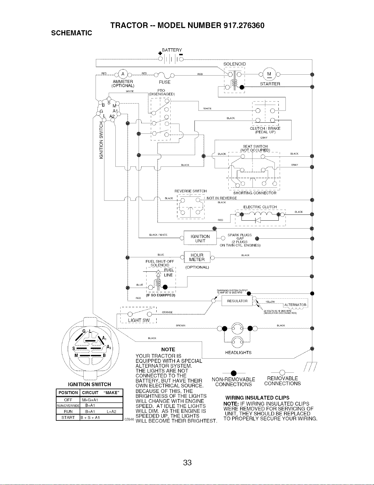
SCHEMATIC
TRACTOR -- MODEL NUMBER 917.276360
BATTERY
SOLENOID
IGNITION SWITCH
POSITION CIRCUIT "MAKE"
OFF M+G+A1
RUN/OVERRIDE B+A1
RUN B+A1 L+A2
START B + S + A1
O
q
SPARK PLUGS
IGNITION
GAP O
UNIT / (2PLUGS
ON TWIN CYL. ENGINES)
i
I ORANGE
LIGHT SW I
NOTE
YOUR TRACTOR IS
EQUIPPED WITH A SPECIAL
ALTERNATOR SYSTEM.
THE LIGHTS ARE NOT
23VOLTSAC @3600£PM
(aEGU_TOR O_SCON_ECTEO)
BLACK
HEADLIGHTS
CONNECTED TO THE
BATTERY, BUT HAVE THEIR
OWN ELECTRICAL SOURCE.
BECAUSE OF THIS, THE
BRIGHTNESS OF THE LIGHTS
WILL CHANGE WITH ENGINE
SPEED. AT IDLE THE LIGHTS
WILL DIM. AS THE ENGINE IS
SPEEDED UP, THE LIGHTS
0284_iWILL BECOME THEIR BRIGHTEST.
• O
NON-REMOVABLE REMOVABLE
CONNECTIONS CONNECTIONS
WIRING INSULATED CLIPS
NOTE: IF WIRING INSULATED CLIPS
WERE REMOVED FOR SERVICING OF
UNIT, THEY SHOULD BE REPLACED
TO PROPERLY SECURE YOUR WIRING.
33

ELECTRICAL
TRACTOR -- MODEL NUMBER 917.276360
/
26
33
34
I
I I I
29
I
I
// i
I
/I
193391-A ROS E
E
34
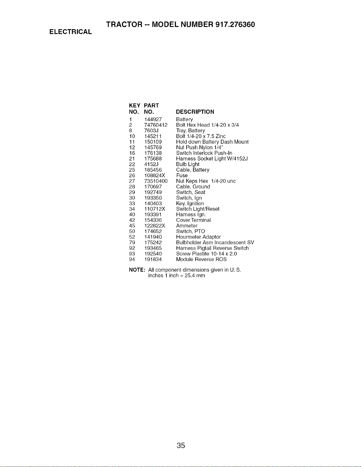
ELECTRICAL
TRACTOR -- MODEL NUMBER 917.276360
KEY PART
NO. NO. DESCRIPTION
1 144927 Battery
2 74760412 Bolt Hex Head 1/4-20 x 3/4
8 7603J Tray, Battery
10 145211 Bolt 1/4-20 x 7.5 Zinc
11 150109 Hold down Battery Dash Mount
12 145769 Nut Push Nylon 1/4"
16 176138 Switch Interlock Push-In
21 175688 Harness Socket Light W/4152J
22 4152J Bulb Light
25 185456 Cable, Battery
26 108824X Fuse
27 73510400 Nut Keps Hex 1/4-20 uric
28 170697 Cable, Ground
29 192749 Switch, Seat
30 193350 Switch, Ign
33 140403 Key, Ignition
34 110712X Switch Light/Reset
40 193391 Harness Ign.
42 154336 Cover Terminal
45 122822X Ammeter
50 174652 Switch, PTO
52 141940 Hourmeter Adaptor
79 175242 Bulbholder Asm Incandescent SV
92 193465 Harness Pigtail Reverse Switch
93 192540 Screw Plastite 10-14 x 2.0
94 191834 Module Reverse ROS
NOTE: All component dimensions given in U. S.
inches 1 inch = 25.4 mm
35

TRACTOR -- MODEL NUMBER 917.276360
CHASSIS AND ENCLOSURES
138
161
158
37
58
21
_a4
_20
19
17 _ 16
56
99
153
158
122
chassis-stealth 43-vgt
36

TRACTOR -- MODEL NUMBER 917.276360
CHASSIS AND ENCLOSURES
KEY PART KEY PART
NO. NO. DESCRIPTION NO. NO. DESCRIPTION
1 180375 Rail, Frame RH 47
2 175282 Drawbar, Gt 50
4 73680700 Nut 7/16-14 56
5 193636X428 Dash 58
6 157882 Dash, Lower Vgt One Piece 68
7 17720408 Screw, Thd Cut 1/4-20 x 1/2 86
8 184668 Support, Battery 91
14 175260X428 Hood Asm 99
16 121794X Cover, Access 122
17 17000612 Screw 3/8-16 x .75 130
18 174515X428 Grille 138
19 19131312 Washer 13/32x13/16 x 12 Ga. 139
20 STD523710 Bolt, Fin Hex 3/8-16 x 1 Gr. 5 142
21 STD541437 Nut Crownlock 3/8-16 unc 144
24 179717X428 Footrest, RH 148
28 179716X428 Footrest, LH 150
30 145052 Saddle, Hydro 152
31 161419 Brace, Supt 1-pc VGT 153
32 161327 Bracket, Pivot Chassis Lh
33 161326 Bracket, Pivot Chassis Rh 156
34 177018 Plate Asm Engine 157
35 19111116 Washer 11/32 x 11/16 x 16 Ga. 158
36 17060512 Screw 5/16-18 x 3/4 161
37 192397X428 Fender Pnt 162
39 175278 Bracket, Axle Front 165
43 136939 Bracket, Spnsn Front Lh 172
44 136940 Bracket, Spnsn Front Rh
45 176018 Bracket Asm., Susp Chas.Rh
17490608
175476
176016
183569
17490508
74780716
180374
177143
192512
191611
Screw Thdrol. 3/8-16 x 1/2
Bracket, Chassis Front
Bracket Asm., Susp Chas. Lh
Bracket Asm., Fender
Screw Thdrol. 5/16-18 x 1/2
Bolt Fin Hex 7/16-14 unc x 1 Gr. 5
Rail, Frame Lh
Rod By Pass
Screw Wshd Hex 10-32 x 5/8
Screw 10 x 3/4 Single Lead Hex
191121X428 Cup Holder
171873 Bolt Shoulder 5/16-18 TT
161897 Bracket Dash Rh
161900 Bracket Dash Lh
164655 Extrusion Bumpers
175352 Duct Heat Hood
177956 Shield Browning
179761 Lightbox Asm W/Lens (Includes
key no. 157)
17000512 Screw 5/16-18 x 3/4
161840 Lens Bar
17670608 Screw Thdrol 3/8-16 x 1/2
179612X428 Console Fuel Window
142432 Screw Hex 1/4-1/2 unc
183554 Bracket Support Tank
17120614 Screw 3/8-16 x .875
NOTE: All component dimensions given in U. S.
inches 1 inch = 25.4 mm
37

TRACTOR -- MODEL NUMBER 917.276360
GROUND DRIVE
9
69
33
drive 6-vgt
42
77
127 120
36
35
6
46
68
34
.145
38

TRACTOR -- MODEL NUMBER 917.276360
GROUND DRIVE
KEY PART KEY PART
NO. NO. DESCRIPTION NO. NO.
1 Transaxle Hydro Gear 94 133835
331-3000 (See Breakdown) 98 141004
2 7070E Key 1/4 x 2.5 106 142918
3 7563R Washer Thrust 107 154739
6 STD561210 Pin, Cotter 108 142917
7 140507 Wheel, Hub Assembly 111 156240
9 140080 Bolt, Hub 112 178558
20 73940800 Nut 114 73800500
22 180235 Lever Asm Shift Lower 117 73900600
23 130564 Knob 120 17000612
29 176600 Brake, Rod 121 175611
33 12000053 Ring E 122 72010520
34 71673 Cap, Parking Brake
35 137648 Rod, Parking Brake 123 192438
36 149412 Spring, Drive Ground 124 165492
37 121749X Washer 25/32 x 1-1/4 x 16 Ga. 126 166002
38 150035 Nyliner
39 74321016 Screw, Fin. #10-24 x 1 127 177362
40 178575 Actuator, Interlock Switch 128 176624
41 73931000 Nut Centerlock 10-24 unc 129 179473
42 8883R Cover, Pedal 130 19131016
46 145170 Retainer, Spring 131 76020312
48 72110614 Bolt, 3/8-16 x 1-3/4 Gr. 5 132 175467
50 131494 Pulley, Idler, Flat 133 175468
52 127783 Pulley, Idler, Grooved 135 177364
55 105706X Bearing, Idler 137 1685H
56 161597 V-Belt 138 1370H
58 74760724 Bolt Fin Hex 7/16-14 x 1-1/2 142 175469
61 143995 Pulley, Transaxle 143 17000512
64 176601 Shaft, Clutch/Brake Pedal 145 163168
65 179613 Bolt, Shoulder 146 140462
68 STD571812 Pin, Roll 147 141322
69 123800X Washer 151 74760514
70 192390X428 Console Shift 152 178705
73 74490548 Bolt Hex FIghd 5/16-18 x 3 Gr.5 153 4497H
74 142432 Screw Hex Wsh. Hi-Lo 1/4-1/2
77 74780716 Bolt Hex 7/16-14 x 1-1/4 Gr. 5
89 73680700 Nut Crownlock 7/16-14 unc
DESCRIPTION
Fastener Christmas Tree
Bracket Shift
O-Ring Asm Hydro Gear
Line Fuel Hydro 15"VGT
Cap Asm Vent Hydro Gear 70109
Spacer Shift Lever VGTH
Washer Nylon High Temp
Nut Lock Hx W/Ins 5/16-18 unc
Nut, Lock Fig. 3/8-16
Screw 3/8-16 x .75
Bracket Strap Torque
Bolt RDHD SQ
5/16-18 unc x 2-1/2
Rod Shift
Bolt Shoulder 5/16-18 x .561
Washer SRRTD
5/16 ID x 1.0 x .125
Link Control Clutch
Spring Drive GRND
Bracket Asm Idler Tensioning
Washer 13/32 x 5/8 x 16 Ga.
Pin Cotter 3/32 x 3/4
Bracket Mtg Hydro 3500 LH VGT
Bracket Mtg Hydro 3500 RH VGT
Link Asm Control Hydro 3500
Nut Lock 5/16-18 NC Thd
Washer Thrust 5/8 x 1.10 x 1/32
Strap Torque HG-3500
Screw Thdrol 5/16-18 x 3/4
Washer Axle Flange HG-3000
Fan 7" Hydro
Washer
Bolt Fin Hex 5/16-18 x 7/8
Bolt hex 5/16-18 x 1
Retainer Spring
NOTE: All component dimensions given in U. S.
inches 1 inch = 25.4 mm
39
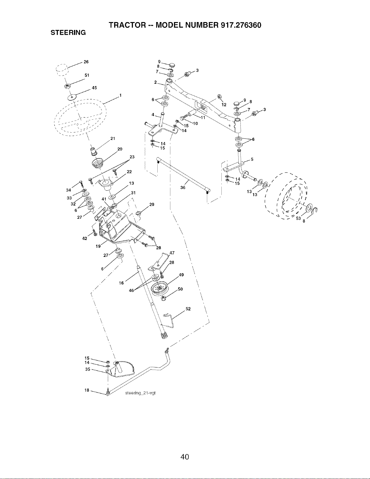
STEERING
TRACTOR -- MODEL NUMBER 917.276360
26
J
_--" 51
20
34
33
32
6
42
23
22
13
,31
29
28
36
\
1313 / / i I I
I I / II
\ I
J
J
18 _ steering 21-vgt
52
4O
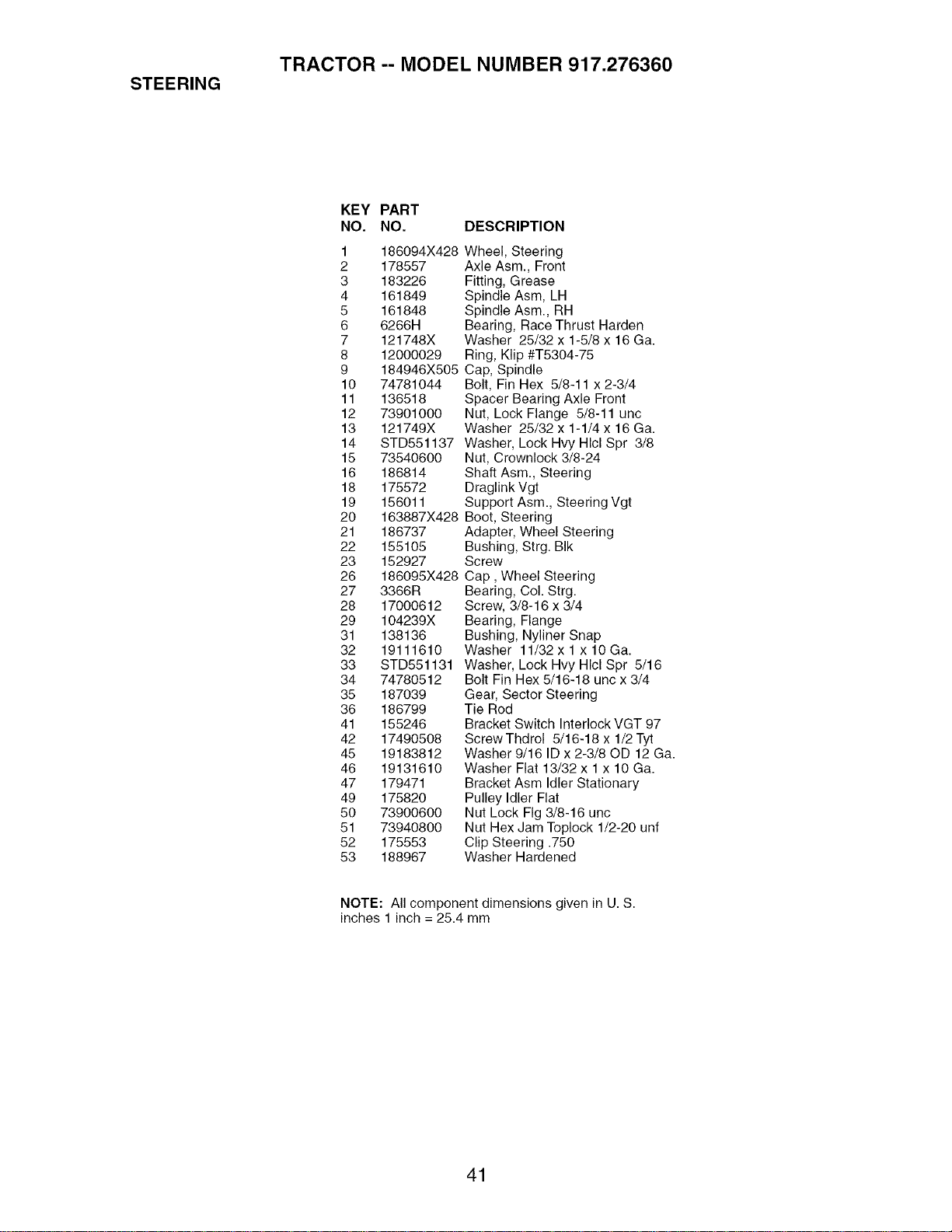
STEERING
TRACTOR -- MODEL NUMBER 917.276360
KEY PART
NO. NO. DESCRIPTION
1 186094X428
2 178557
3 183226
4 161849
5 161848
6 6266H
7 121748X
8 12000029
9 184946X505
10 74781044
11 136518
12 73901000
13 121749X
14 STD551137
15 73540600
16 186814
18 175572
19 156011
20 163887X428
21 186737
22 155105
23 152927
26 186095X428
27 3366R
28 17000612
29 104239X
31 138136
32 19111610
33 STD551131
34 74780512
35 187039
36 186799
41 155246
42 17490508
45 19183812
46 19131610
47 179471
49 175820
50 73900600
51 73940800
52 175553
53 188967
Wheel, Steering
Axle Asm., Front
Fitting, Grease
Spindle Asm, LH
Spindle Asm., RH
Bearing, Race Thrust Harden
Washer 25/32 x 1-5/8 x 16 Ga.
Ring, Klip #T5304-75
Cap, Spindle
Bolt, Fin Hex 5/8-11 x 2-3/4
Spacer Bearing Axle Front
Nut, Lock Flange 5/8-11 unc
Washer 25/32 x 1-1/4 x 16 Ga.
Washer, Lock Hvy HIcl Spr 3/8
Nut, Crownlock 3/8-24
Shaft Asm., Steering
Draglink Vgt
Support Asm., Steering Vgt
Boot, Steering
Adapter, Wheel Steering
Bushing, Strg. BIk
Screw
Cap, Wheel Steering
Bearing, Col. Strg.
Screw, 3/8-16 x 3/4
Bearing, Flange
Bushing, Nyliner Snap
Washer 11/32xlx10Ga.
Washer, Lock Hvy Hlcl Spr 5/16
Bolt Fin Hex 5/16-18 unc x 3/4
Gear, Sector Steering
Tie Rod
Bracket Switch Interlock VGT 97
Screw Thdrol 5/16-18 x 1/2 Tyt
Washer 9/16 ID x 2-3/80D 12 Ga.
Washer Flat 13/32 x 1x 10 Ga.
Bracket Asm Idler Stationary
Pulley Idler Flat
Nut Lock Fig 3/8-16 unc
Nut Hex Jam Toplock 1/2-20 unf
Clip Steering .750
Washer Hardened
NOTE: All component dimensions given in U. S.
inches 1 inch = 25.4 mm
41
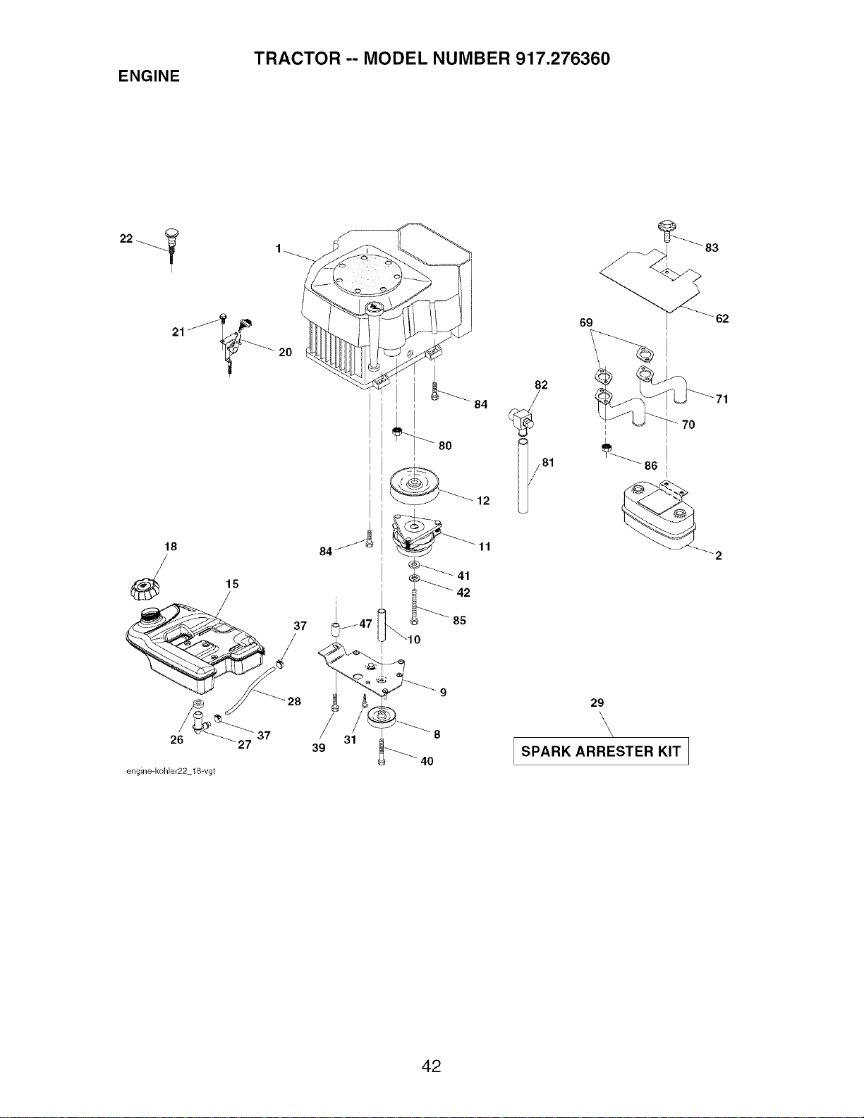
ENGINE
TRACTOR -- MODEL NUMBER 917.276360
18
37
26 27
engine-kohler22 18-vgt
84
39
i
85
3
31 _ 40
84
12
11
82
69 _62
29
\\
\
/
SPARK ARRESTER KIT I
J
42

ENGINE
TRACTOR -- MODEL NUMBER 917.276360
KEY PART
NO. NO. DESCRIPTION
1 Engine (See Breakdown) Kohl
Model No. CV730-0044
2 149723 Muffler
8 121361X Pulley V-Idler
9 177748 Keeper Asm. Belt Engine
10 175288 Bushing
11 179335 Clutch Electric
12 143996 Pulley Engine VGT Elect Clutch
15 179115 Tank Fuel Rear 5.0 Yt/Gt 96
18 179124X428 Cap Asm Fuel W/Gauge
20 177328X505 Control Throttle
21 191611 Screw 10 x 3/4 Single Lead Hex
22 187768X505 Control Choke
26 3645J Bushing
27 139277 Stem Tank Fuel
28 7834R Fuel Line
29 137180 Spark Arrester Kit
31 145006 Clip Push-In Hinged
37 123487X Clamp Hose
39 17490636 Screw TT 3/8-16 x 2-1/4 uric
40 17490664 Screw TT 3/8-16 x 4 unc
41 126197X Washer 1-1/20D x15/32 ID x .250
42 STD551143 Washer Lock 7/16
47 175287 Spacer Engine
62 146629 Shield Heat Muffler
69 Gasket (Order from engine mfgr.)
70 175545 Tube Exhaust LH
71 175546 Tube Exhaust RH
80 M73030800 Nut Flange M8-1.25
81 188800 Tube Drain Oil
82 188799 Drain Oil Valve
83 171877 Bolt 5/16-18 unc x 3/4
84 17060624 Screw 3/8-16 x 1-1/2
85 179953 Bolt Hex 7/16 - 20 x 3.75 Gr. 5
86 184362 Nut hex Flange Toplock M8-1.25
NOTE: All component dimensions given in U. S.
inches 1 inch = 25.4 mm
43
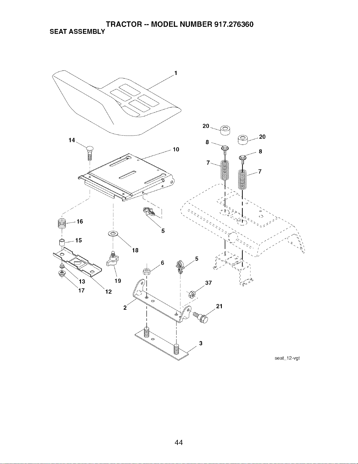
TRACTOR -- MODEL NUMBER 917.276360
SEAT ASSEMBLY
17
18
19
12
10
I
I
I
seat 12-vgt
44

TRACTOR -- MODEL NUMBER 917.276360
SEAT ASSEMBLY
KEY PART
NO. NO. DESCRIPTION
1 180598 Seat
2 180166 Bracket, Pivot Seat
3 140675 Strap, Fender Assembly
5 145006 Clip, Push In, Hinged
6 STD541437 Nut 3/8-16 uric
7 124181X Spring, Seat Cprsn
8 171877 Bolt 5/16-18Uric x 3/4 w/Sems
10 180186 Pan, Seat
12 174648 Bracket, Mounting Switch
13 121248X Bushing, Snap
14 72050412 Bolt, Carriage 1/4-20 x 1-1/2
15 121249X Spacer, Split
16 123740X Spring, Cprsn
17 123976X Nut, Lock 1/4 Lge Fig Gr. 5
18 19171912 Washer 17/32 x 1-3/16 x 12 Ga.
19 166369 Knob, Seat
20 124238X Cap, Spring Seat
21 171852 Bolt, Shoulder 5/16-18
37 73800500 Nut, Lock Hx w/Ins. 5/16-18
NOTE: All component dimensions given in U. S.
inches 1 inch = 25.4 mm
45
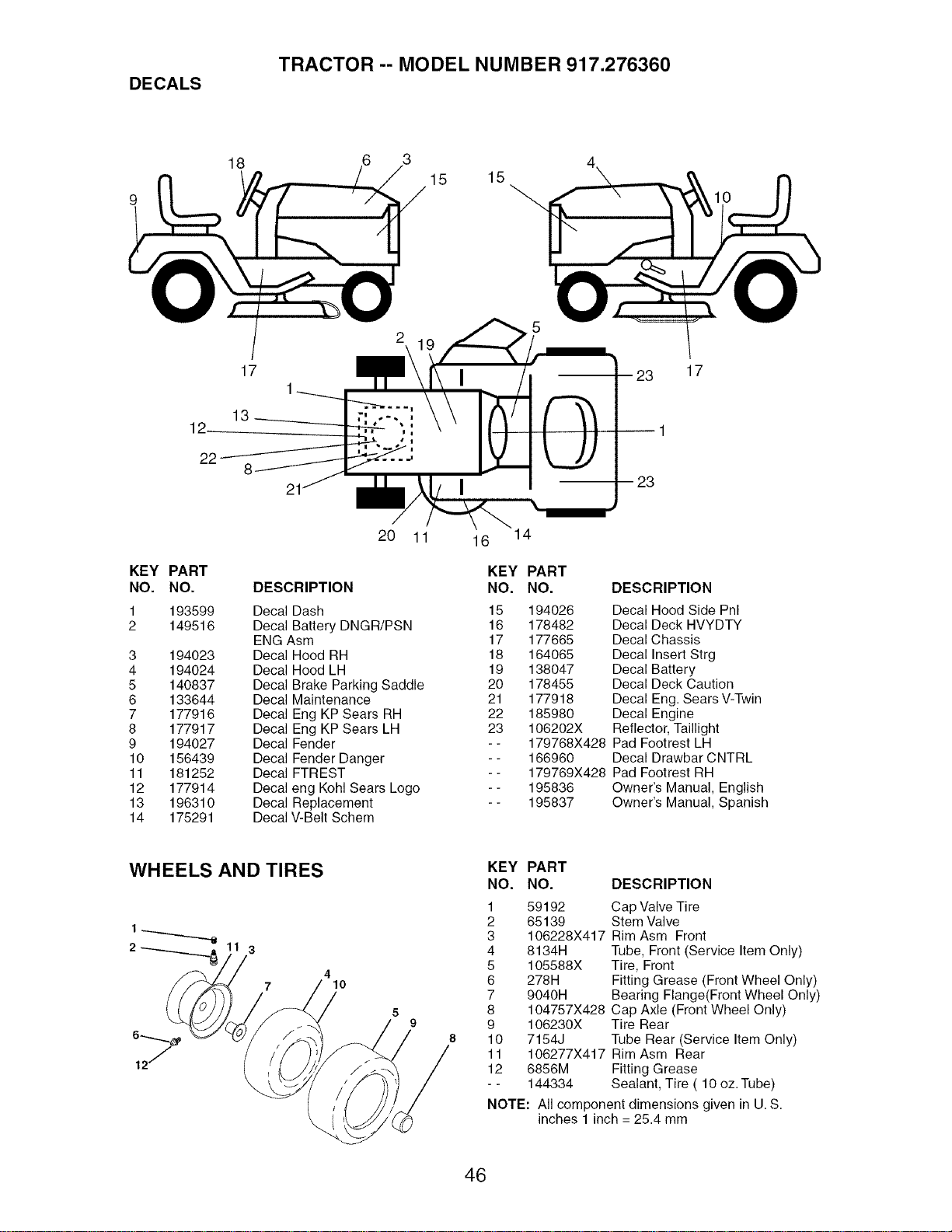
DECALS
TRACTOR -- MODEL NUMBER 917.276360
18
3
15
15
10
17 17
12_
22
8
20 11
KEY PART
NO. NO. DESCRIPTION
1 193599 Decal Dash
2 149516 Decal Battery DNGR/PSN
ENG Asm
3 194023 Decal Hood RH
4 194024 Decal Hood LH
5 140837 Decal Brake Parking Saddle
6 133644 Decal Maintenance
7 177916 Decal Eng KP Sears RH
8 177917 Decal Eng KP Sears LH
9 194027 Decal Fender
10 156439 Decal Fender Danger
11 181252 Decal FTREST
12 177914 Decal eng Kohl Sears Logo
13 196310 Decal Replacement
14 175291 Decal V-Belt Schem
16 14
KEY PART
NO. NO. DESCRIPTION
15 194026 Decal Hood Side Pnl
16 178482 Decal Deck HVYDTY
17 177665 Decal Chassis
18 164065 Decal Insert Strg
19 138047 Decal Battery
20 178455 Decal Deck Caution
21 177918 Decal Eng. Sears V-Twin
22 185980 Decal Engine
23 106202X Reflector, Taillight
- - 179768X428 Pad Footrest LH
- - 166960 Decal Drawbar CNTRL
- - 179769X428 Pad Footrest RH
- - 195836 Owner's Manual, English
- - 195837 Owner's Manual, Spanish
WHEELS AND TIRES
2 3
4
10
5
9
KEY PART
NO. NO. DESCRIPTION
1 59192 Cap Valve Tire
2 65139 Stem Valve
3 106228X417 Rim Asm Front
4 8134H Tube, Front (Service Item Only)
5 105588X Tire, Front
6 27814 Fitting Grease (Front Wheel Only)
7 904014 Bearing Flange(Front Wheel Only)
8 104757X428 Cap Axle (Front Wheel Only)
9 106230X Tire Rear
10 7154J Tube Rear (Service Item Only)
11 106277X417 Rim Asm Rear
12 6856M Fitting Grease
- - 144334 Sealant, Tire ( 10 oz. Tube)
NOTE: All component dimensions given in U. S.
inches 1 inch = 25.4 mm
46
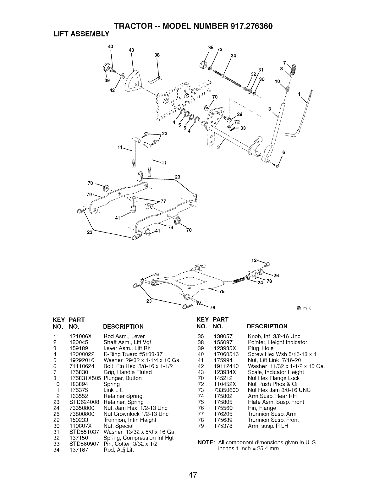
TRACTOR -- MODEL NUMBER 917.276360
LIFT ASSEMBLY
40 43 35 73
31
32
39 30
I I
i
29
8
10
\
3\
}
23
23
7O
KEY PART
NO. NO.
1 121006X
2 180045
3 159189
4 12000022
5 19292016
6 71110624
7 175830
8 175831X505
10 183894
11 175375
12 163552
23 STD624008
24 73350800
26 73800800
29 150233
30 110807X
31 STD551037
32 137150
33 STD560907
34 137167
78
lift rh 8
DESCRIPTION
Rod Asm., Lever 35 138057
Shaft Asm., Lift Vgt 38 155097
Lever Asm., Lift Rh 39 123935X
E-Ring Truarc #5133-87 40 17060516
Washer 29/32 x 1-1/4 x 16 Ga. 41 175994
Bolt, Fin Hex 3/8-16 x 1-1/2 42 19112410
Grip, Handle Fluted 43 123934X
Plunger, Button 70 145212
Spring 72 110452X
Link Lift 73 73350600
Retainer Spring 74 175802
Retainer, Spring 75 175805
Nut, Jam Hex 1/2-13 Unc 76 175560
Nut Crownlock 1/2-13 Unc 77 176205
Trunnion, Infin Height 78 175689
Nut, Special 79 175378
Washer 13/32 x 5/8 x 16 Ga.
Spring, Compression Inf Hgt
Pin, Cotter 3/32 x 1/2
Rod, Adj Lift
KEY PART
NO. NO. DESCRIPTION
Knob, Inf 3/8-16 Unc
Pointer, Height Indicator
Plug, Hole
Screw Hex Wsh 5/16-18 x 1
Nut, Lift Link 7/16-20
Washer 11/32 x 1-1/2 x 10 Ga.
Scale, Indicator Height
Nut Hex Flange Lock
Nut Push Phos & Oil
Nut Hex Jam 3/8-16 UNC
Arm Susp. Rear RH
Plate Asm. Susp. Front
Pin, Flange
Trunnion Susp. Arm
Trunnion Susp. Front
Arm, susp. R LH
NOTE: All component dimensions given in U. S.
inches 1 inch = 25.4 mm
47
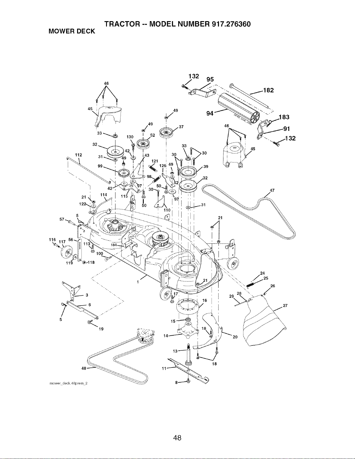
TRACTOR -- MODEL NUMBER 917.276360
MOWER DECK
46
132
95
112
21
122.
j49
I 52
130
®
121
33
,30
46
1
47
116 4
26
mower deck.48prem 2
48

TRACTOR -- MODEL NUMBER 917.276360
MOWER DECK
KEY PART KEY PART
NO. NO. DESCRIPTION NO. NO. DESCRIPTION
1 180358 Deck Weldment Mower 48 49 73900600
3 178915 Bracket Asm., Sway Bar 50 72110612
5 4939M Retainer Spring 52 175820
6 178024 Sway Bar 56 155986
8 174365 Bolt 7/16 Asm. Blade 57 156941
(The following blades are 91 180535
available) 94 176066
11 180054 Blade, 48" Hi-Lift 95 180534
13 174360 Shaft Asm. w/Lower Bearing 97 178515
14 174358 Mandrel Asm. 98 179479
15 110485X Bearing, Ball, Mandrel 99 189993
16 174493 Stripper Mandrel Deck 100 72110616
17 72110610 Bolt RDHD Sq Neck3/8-16x1.25 110 175016
18 72140505 Bolt, Carriage 5/16-18 x 5/8 112 174387
19 132827 Bolt, Hex Hd, Shoulder 5/16-18 113 72110506
20 174378 Baffle, Vortex Mower 114 174384
21 73680500 Nut, Crownlock 5/16-18 Unc 115 174609
24 105304X Cap, Sleeve 116 193406
25 178102 Spring, Torsion 117 174873
26 110452X Nut, Push 118 73930600
27 180655X428 Deflector Shield 119 19121414
28 19111016 Washer 11/32 x 5/8 x 16 Ga. 121 174371
29 131491 Rod, Hinge 122 174606
30 173984 Screw, Thdroll Washer Head 126 174372
31 187690 Washer, Spacer 130 17000616
32 153535 Pulley, Mandrel 132 17000612
33 178342 Nut, Fig. Top Lock Cntr. 9/16 180 73800500
37 177968 Pulley, Idler, Flat 182 179127
39 174375 Pulley, Idler, Driven 183 163552
42 165723 Spacer, Retainer 184 173979
43 174373 Arm, Idler Secondary - - 174356
45 180806 Cover, Mandrel Deck
46 137729 Screw, Thdroll. 1/4-20 x 5/8 - - 181579
47 180808 V-Belt, Mower, Secondary
48 174368 V-Belt, Mower, Primary
Nut, Lock 3/8-16 Unc
Bolt, Carr. 3/8-16 x 1-1/2 Gr. 5
Pulley Idler Flat
Bar Pnt Adj.
Pin Head Rivet
Bracket, Asm Noseroller, RH
Noseroller
Bracket, Asm Noseroller, LH
Washer Hardened
Spring Primary Drive
Pulley Idler"V"
Bolt RDHD Sqnk 3/8-16 Unc x 2
Arm Spring Secondary
Link Tension Relief Lever
Bolt 5/16-18 x 3/4
Tension Asm. Relief Lever
Arm Spring Tension Relief
Bolt, Shoulder
Gauge Wheel
Nut, Centerlock 3/8-16 Unc
Washer 3/8 x 7/8 x 14 Ga.
Spring Secondary Drive
Bushing Pivot Tension Relief
Arm, Idler, Primary Deck
Screw 3/8-16 x 1.0
Screw 3/8-16 x .75
Nut Lock Hex W/Inc. 5/16-18 Unc
Rod Roller Nose
Retainer Spring
Keeper Belt Idler
Mandrel Assembly
(Includes Key Nos. 13-15 and 33)
Replacement Mower, Complete
NOTE: All component dimensions given in U. S.
inches 1 inch = 25.4 mm
49
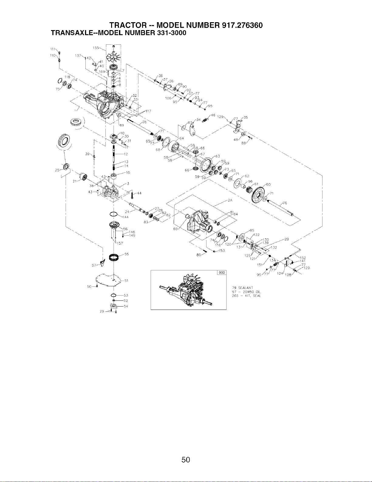
TRACTOR -- MODEL NUMBER 917.276360
TRANSAXLE--MODEL NUMBER 331-3000
111X
\
157
_o_-_
85
_1 41
95
79 SEAl ANT
97 - 20W50 O}L
20,3 K}T, SEA
50
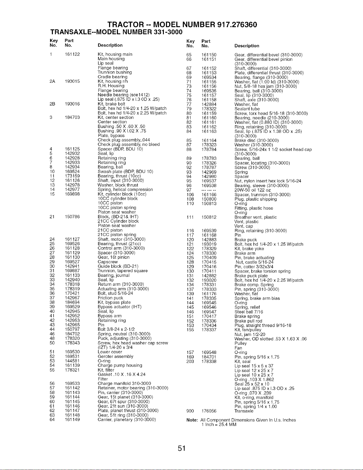
TRACTOR -- MODEL NUMBER 917.276360
TRANSAXLE--MODEL NUMBER 331-3000
Key Part Key Part
No. No. Description No. No. Description
1 161122 Kit, housing main 65 161150
Main housing 66 161151
Lip seal
Flange bearing 67 161152
Trunnion bushing 68 161153
Cradle bearing 69 169534
2A 193016 Kit, housing r/h 71 161155
R.H. Housing 73 161156
Flange bearing 74 169535
Needle bearing (sce1412) 75 161157
Lip seal (.875 ID x 1.30D x .25) 76 161158
2B 193016 Kit, brake bolt 77 142884
Bolt, hex hd 1/4-20 x 1.25W/patch 79 178322
Bolt, hex hd 1/4-20 x 2.25 W/patch 80 161159
3 184703 Kit, center section 81 161160
Center section 82 161161
Bushing .50X .60X .50 83 161162
Bushing .90 X 1.02X .75 84 161163
Plate, bypass
Check plug assembly..044 85 161164
Check plug assembly, no bleed 87 178323
4 161125 Spacer (BDE BDU 10) 88 178784
5 142932 Seal, lip
6 142928 Retaining ring 89 178783
7 142933 Retaining ring 90 178326
8 142934 Bearing, ball 92 178787
10 169524 Swash plate (BDP, BDU 10) 93 142969
11 173159 Bearing, thrust (10cc) 94 142980
12 161126 Shaft, input (310-3000) 95 169537
13 142978 Washer, block thrust 96 169538
14 142977 Spring, helical compression 97
15 169898 Kit, cylinder block (10cc) 106 161166
10CC cylinder block 108 150800
10CC piston 110 150813
10CC piston spring
Piston seat washer
21 150786 Block, (BD-21& IHT) 111 150812
21CC Cylinder block
Piston seat washer
21CC piston 116 169539
21CC piston spring 117 161168
24 161127 Shaft, motor (310-3000) 120 142883
25 169526 Bearing, thrust (21cc) 121 193019
26 161128 Control arm (310-3000) 122 178329
27 161129 Spacer (310-3000) 124 178330
28 161130 Gear, 16t pinion 125 170409
29 169527 Capscrew 128 170415
30 142941 Guide block (BD-21) 129 170416
31 169887 Trunnion, tapered square 130 170411
32 161133 Bearing, journal 131 142882
33 142940 Seal, lip 132 193020
34 178318 Return arm (310-3000) 134 178331
35 178319 Actuating arm (310-3000) 137 178333
36 170421 Bolt, stud 5/16-24 139 161176
37 142967 Friction puck 141 178335
38 184694 Kit, bypass plate 144 169545
39 169529 Bypass actuator (IHT) 145 169546
40 142945 Seal, lip 146 169547
41 142952 Bypass arm 151 170417
42 142953 Retaining ring 152 178336
43 142965 Pin 153 170434
44 150797 Bolt 3/8-24 x 2-1/2 155 178337
46 184702 Spring, neutral (310-3000)
48 178320 Puck, adjusting (310-3000)
50 178343 Screw, hex head washer cap screw
(IZT) 1/4-20 x 3/4
51 169530 Lower cover 157 169548
52 169531 Geroter assembly 169 184701
53 144581 O-ring 203 178338
54 161139 Charge pump housing
55 178321 Kit, filter
Gasket .10 X .16 X 4.24
Filter
56 169533 Charge manifold 310-3000
57 161142 Retainer, motor bearing (310-3000)
58 161143 Pin, carrier (310-3000)
59 161144 Gear, 15t planet (310-3000)
60 161145 Gear, 67t spur (310-3000)
61 161146 Gear, 21t sun (310-3000)
62 161147 Plate, planet thrust (310-3000) 900 176056
63 161148 Gear, 51t ring (310-3000)
64 161149 Carrier, planetary (310-3000)
Gear, differential bevel (310-3000)
Gear, differential bevel pinion
(310-3000)
Shaft, differential (310-3000)
Plate, differential thrust (310-3000)
Bearing, flange (310-3000)
Washer, flat (1.00 Id) (310-3000)
Nut, 5/8-18 hex jam (310-3000)
Bearing, ball (310-3000)
Seal, lip (310-3000)
Shaft, axle (310-3000)
Washer, flat
Sealant tube
Screw, torx head 5/16-18 (310-3000)
Bearing, needle (210-3000)
Washer, flat (0.880 ID) (310-3000)
Ring, retaining (310-3000)
Seal, lip (.875 ID x 1.38 OD x .25)
(310-3000)
Brake disc (310-3000)
Washer (310-3000)
Screw, 5/16-24x 1 1/2 socket head cap
(310-3000)
Bearing, ball
Spacer, locating (310-3000)
Screw (310-3000)
Spring
Spacer
Nut, nylon insert hex lock 5/16-24
Bearing, sleeve (310-3000)
20W-50 oil 122 oz
Spacer, trunnion (310-3000)
Plug, plastic shipping
O-ring
Fitting, plastic hose
O-ring
Breather vent, plastic
Vent, plastic
Vent, cap
Ring, retaining (310-3000)
Pin
Brake puck
Bolt, hex hd 1/4-20 x 1.25 W/patch
Kit, brake yoke
Brake arm
Pin, brake actuating
Nut, castle 5/16-24
Pin, cotter 3/32x3/4
Spacer, brake torsion spring
Brake puck plate
Bolt, hex hd 1/4-20 x 2.25 W/patch
Brake comp. Spring
Pin, spring (310-3000)
Washer. flat
Spring, brake arm bias
O-ring
Spring, relief
Steel ball 7/16
Brake spring
Brake pull rod
Plug, straight thread 9/16-18
Kit, fan/pulley
Nut, jam 1/2-20
Washer, OD slotted .53 X 1.63 X .06
Pulley
Fan
O-ring
Pin, spring 5/16 x 1.75
Kit, seal
Lip seal 15x5x37
Lip seal 12x25x7
Lip seal 10x25x7
O-ring .103 X 1.862
Seal 25 x 52 x 10
Lip seal .875 ID x 1.30D x .25
O-ring .070 X .239
Kit, o-ring, manifold
Pin, spring 5/16 x 1.75
Pin, spring 1/4 x 1.00
Transaxle
Note: All Component Dimensions Given In U.s. Inches
1 Inch = 25.4 MM
51
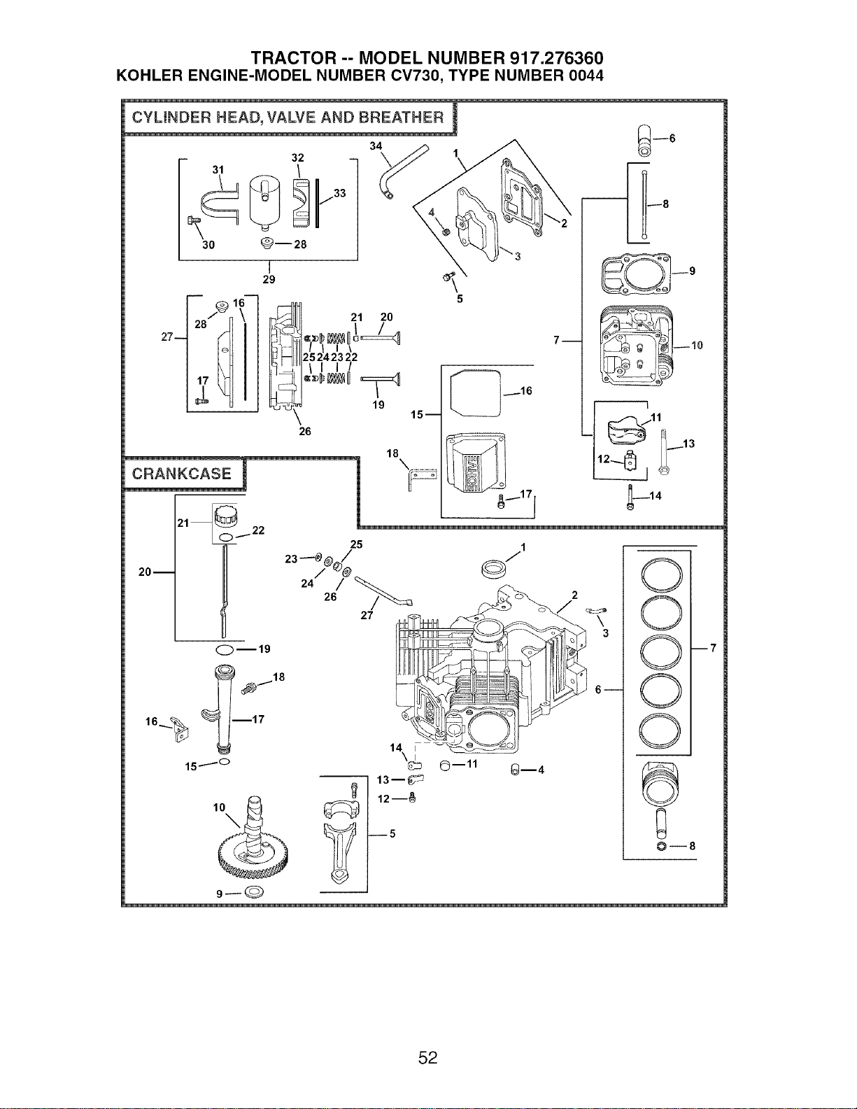
TRACTOR -- MODEL NUMBER 917.276360
KOHLER ENGINE-MODEL NUMBER CV730, TYPE NUMBER 0044
CYLINDER HEAD, VALVE
27--
- 32
31 /
30 _--28
AND BREATHER
W
_33 _
I
29
2-_1_- _
o ii-
17_ iIF,_
CRANKCASE
21 2O
/ l I\
25 24 23 22
II I/
19
15--
18
1
5
7--
_8
L
--_11! ._.._13
20--
21 _i.. 22
25
1°_
1510
--I 13--_
12--_
5
©--11 _--4
14
0
0
0
0
0
9_
--7
52

TRACTOR -- MODEL NUMBER 917.276360
KOHLER ENGINE-MODEL NUMBER 0V730, TYPE NUMBER 0044
HEAD/VALVE/BREATHER
CRANKCASE
KEY PART KEY PART
NO. NO. DESCRIPTION NO. NO.
1. 24-033-03-S
2. 24-041-51 -S
3. 24-096-87-S
4. M-645020-S
5. 25 139 60-S
6. 25-351-01 -S
7. 24-755-66-S
8. 24-411-05-S
9. 24-841-03-S
10. 24-318-72-S
11. 25-186-01-S
12. 24-599-01-S
13. 12 086 16-S
14. 66-086-07-S
15. 24-755-141-S
16. 24-153-28-S
17. M-651030-S
18. 24-445-01 -S
19. 24-016-01-S
24-016-02-S
20. 24-017-01-S
24-017-02-S
21. 66-032-05-S
22. 235011-S
23. 24-089-02-S
24. 12-173-01-S
25. 12-755-03-S
26. 24-318-69-S
27. 24-755-142-S
28. 25-313-03-S
29. 24-755-57-S
30. M-545016-S
Kit, breather cover w/gasket 1.
(Includes 2, 3) 2.
Gasket, breather
Cover, breather 3.
Screw, hex. flange 4.
M6x1.0x20 (4) 5.
Plug, hex. ctsk. 1/8"
Lifter, valve (4) 6.
Kit, valve train (Includes 8,
11,12)
Rod, push (4)
Kit, cylinder head gasket (2)
(Includes 13) 7.
Head assembly, #2 cylinder
Arm, rocker (4)
Pivot, rocker arm (4) 8.
Screw, hex. flange 9.
M10x1.5x90 (8)
Screw, hex. flange
M6x1.0x34 (4)
Kit, valve cover - plain
(Includes 16,17)
O-Ring
Screw, hex. flange 10.
M6x1.0x30 (4) 11,
Strap, lifting 12.
Valve, exhaust (Std.) (2)
Valve, exhaust (.25) (2) 13.
Valve, intake (Std.) (2) 14.
Valve, intake (.25) (2) 15.
Seal, valve stem (2) 16.
Retainer, spring (4) 17.
Spring, valve (4) 18.
Cap, valve spring (4)
Kit, retainer (4) 19.
Head assembly, #1 cylinder 20.
Kit, valve cover - breather
(Includes 16,17,29) 21.
Grommet, rubber 22.
Kit, breather separator 23.
(Includes 29,31-34) 24.
Screw, hex. flange 25.
M5x0.8x16 (2) 26.
Strap, breather 27.
Bracket, breather separator
Spacer
Hose, breather
Kit, cylinder head hardware
31. 24-445-02-S
32. 24-126-44-S
33. 24-112-12-S
34. 24-326-74-S
NOT ILLUSTRATED
24 755 147-S
DESCRIPTION
24-032-01-S
24-294-13-S
24-380-13-S
24-067-13-S
24-067-14-S
24-874-08-S
24-874-16-S
24-874-20-S
24-874-21-S
24-108-05-S
24-108-06-S
24-108-07-S
24-018-01-S
12-422-09-S
12-422-13-S
12-422-07-S
12-422-08-S
12-422-10-S
12-422-11-S
12-422-12-S
24-012-16-S
52-139-09-S
M-545010-S
24-018-04-S
24-402-05-S
12-153-01-S
24-126-19-S
12-123-04-S
M-545016-S
12-153-02-S
24-038-04-S
24-755-46-S
25 153 02-S
24-018-09-S
M-931010-S
28-032-09-S
24-468-15-S
24-144-38-S
Seal, front oil
Crankcase (USE: Miniblock
24 782 14)
Fitting
Pin, locating (6)
Connecting Rod (Std.) (2)
Connecting Rod (,25) (2)
Piston w/Ring Set (Std,) (2)
(Includes 7, 8)
Piston w/Ring Set (.08)
Piston w/Ring Set (.25)
Piston w/Ring Set (.50)
Ring Set (Std. & .08) (2)
Ring Set (.25)
Ring Set (.50)
Retainer, piston pin (4)
Shim, camshaft (A.R.)
Shim, camshaft (A.R.)
Shim, camshaft (A.R.)
Shim, camshaft (A.R.)
Shim, camshaft
Shim, camshaft (A.R.)
Shim, camshaft (A.R.)
Camshaft
Plug, cup
Screw, hex. flange
M5x0.8xl 0 (2)
Retainer, reed (2)
Reed, breather (2)
O-Ring, lower oil fill tube
Bracket, oil fill tube
Tube, oil fill
Screw, hex. flange
M5x0.8x 16
O-Ring, upper oil fill tube
Dipstick assembly (Includes
21,22)
Kit, oil fill cap (Includes 22)
O-Ring, dipstick
Ring, retainer
Washer, nylon (top)
Seal, governor cross shaft
Washer (bottom)
Shaft, governor cross
NOTE: All component dimensions given in U.S.
inches 1 inch = 25.4 mm
53
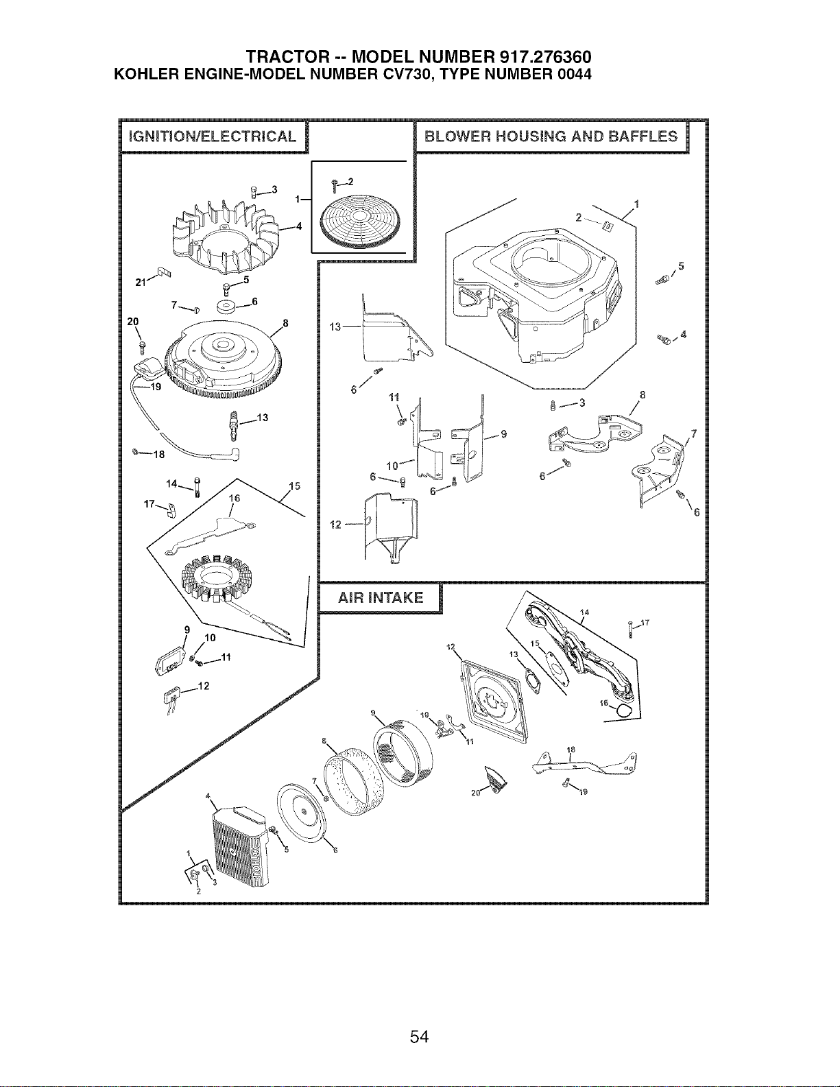
TRACTOR -- MODEL NUMBER 917.276360
KOHLER ENGINE-MODEL NUMBER CV730, TYPE NUMBER 0044
IGNITION/ELECTRICAL
_/3 1--
i13
BLOWER HOUSING AND BAFFLES F
_/5
6/
%/4
2
54
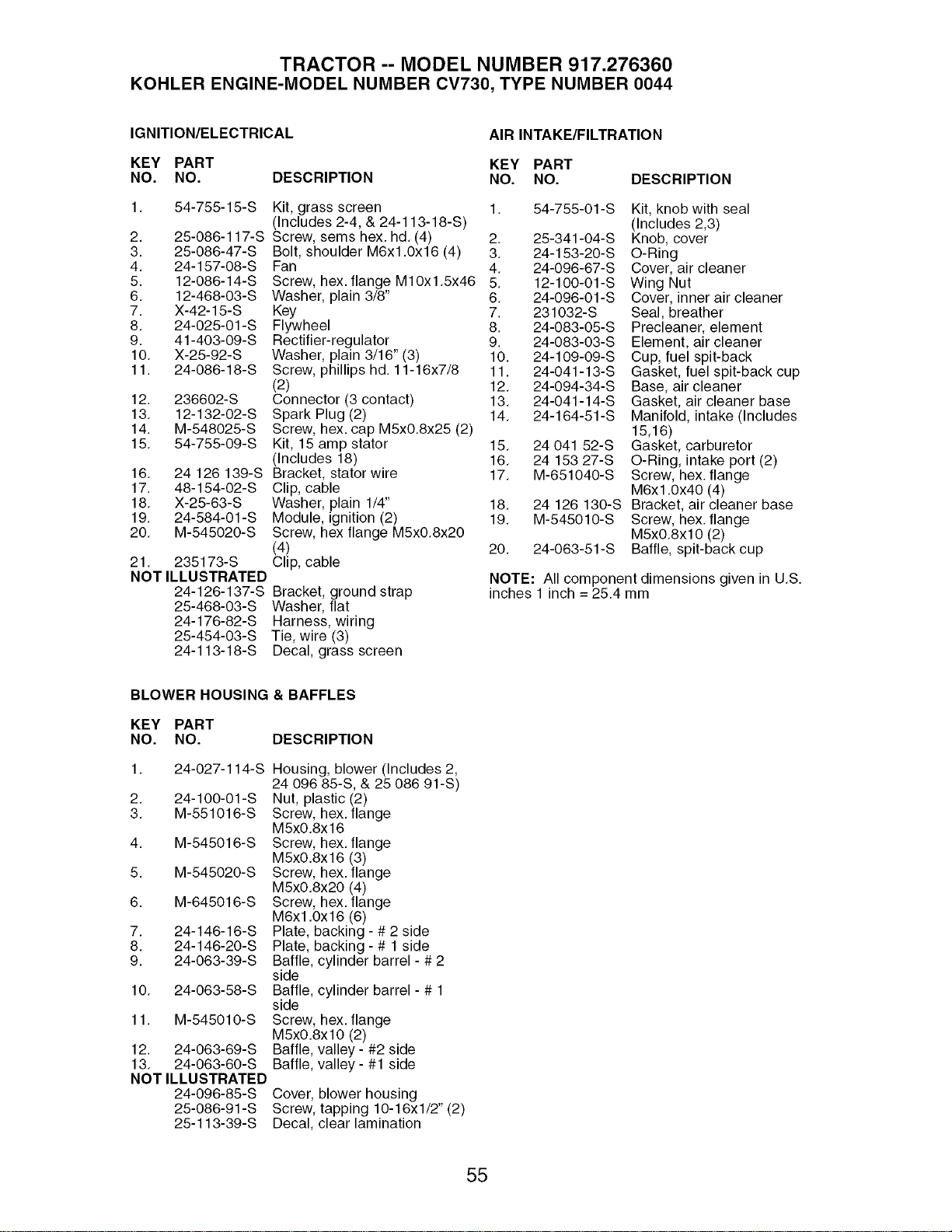
TRACTOR -- MODEL NUMBER 917.276360
KOHLER ENGINE-MODEL NUMBER CV730, TYPE NUMBER 0044
IGNITION/ELECTRICAL
AIR INTAKE/FILTRATION
KEY PART KEY PART
NO. NO. DESCRIPTION NO. NO.
1. 54-755-15-S Kit, grass screen 1. 54o755-01 -S
(includes 2-4, & 24-113-18-S)
2. 25-086-117-S Screw, sems hex. hd. (4) 2. 25-341-04-S
3. 25-086-47-S Bolt, shoulder M6x1.0x16 (4) 3. 24-153-20-S
4. 24-157-08-S Fan 4. 24-096-67-S
5. 12-086-14-S Screw, hex. flange M10x1.5x46 5. 12-100-01-S
6. 12-468-03-S Washer, plain 3/8" 6. 24-096-01-S
7. X-42-15-S Key 7. 231032-S
8. 24-025-01-S Flywheel 8. 24-083-05-S
9. 41-403-09-S Rectifier-regulator 9. 24-083-03-S
10. X-25-92-S Washer, plain 3/16" (3) 10. 24-109-09-S
11. 24-086-18-S Screw, phillips hd. 11-16x7/8 11. 24-041-13-S
(2) 12. 24-094-34-S
12. 236602-S Connector (3 contact) 13. 24-041-14oS
13. 12-132-02-S Spark Plug (2) 14. 24-164-51-S
14. M-548025-S Screw, hex. cap M5x0.8x25 (2)
15. 54-755-09-S Kit, 15 amp stator 15. 24 041 52-S
(Includes 18) 16. 24 153 27-S
16. 24 126 139-S Bracket, stator wire 17. M-651040-S
17. 48-154-02-S Clip, cable
18. X-25-63-S Washer, plain 1/4" 18. 24 126 130-S
19. 24-584-01 -S Module, ignition (2) 19. M-545010-S
20. M-545020-S Screw, hex flange M5x0.8x20
(4) 20. 24-063-51-S
21. 235173-S Clip, cable
NOT ILLUSTRATED
24-126-137-S Bracket, ground strap
25-468-03-S Washer, flat
24-176-82-S Harness, wiring
25-454-03-S Tie, wire (3)
24-113-18-S Decal, grass screen
DESCRIPTION
Kit, knob with seal
(Includes 2,3)
Knob, cover
O-Ring
Cover, air cleaner
Wing Nut
Cover, inner air cleaner
Seal, breather
Precleaner, element
Element, air cleaner
Cup, fuel spit-back
Gasket, fuel spit-back cup
Base, air cleaner
Gasket, air cleaner base
Manifold, intake (includes
15,16)
Gasket, carburetor
O-Ring, intake port (2)
Screw, hex. flange
M6x1.0x40 (4)
Bracket, air cleaner base
Screw, hex. flange
M5x0.8x10 (2)
Baffle, spit-back cup
NOTE: All component dimensions given in U.S.
inches 1 inch = 25.4 mm
BLOWER HOUSING & BAFFLES
KEY PART
NO. NO. DESCRIPTION
1. 24-027-114-S Housing, blower (Includes 2,
24 096 85-S, & 25 086 91-S)
2. 24-100-01-S Nut, plastic (2)
3. M-551016-S Screw, hex.flange
M5xO.8x 16
4. M-545016-S Screw, hex.flange
M5xO.8x16 (3)
5. M-545020-S Screw, hex. flange
M5xO.8x20 (4)
6. M-645016-S Screw, hex. flange
M6x1.0x16 (6)
7. 24-146-16-S Plate, backing - # 2 side
8. 24-146-20-S Plate, backing- # 1 side
9. 24-063-39-S Baffle, cylinder barrel - # 2
side
10. 24-063-58-S Baffle, cylinder barrel - # 1
side
11. M-545010-S Screw, hex. flange
M5xO.8xlO (2)
12. 24-063-69-S Baffle, valley- #2 side
13. 24-063-60-S Baffle, valley- #1 side
NOT ILLUSTRATED
24-096-85-S Cover, blower housing
25-086-91-S Screw, tapping 10-16xl/2" (2)
25-113-39-S Decal, clear lamination
55
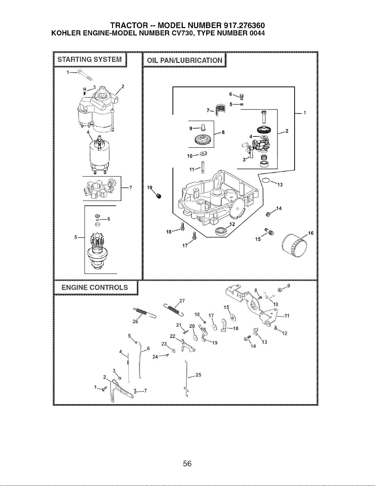
TRACTOR -- MODEL NUMBER 917.276360
KOHLER ENGINE-MODEL NUMBER CV730, TYPE NUMBER 0044
STARTING SYSTEM I
2
c@___6
OiL PAN/LUBRICATION !
16
_NTROLS q
26
24_
56

TRACTOR -- MODEL NUMBER 917.276360
KOHLER ENGINE-MODEL NUMBER CV730, TYPE NUMBER 0044
STARTING SYSTEM
KEY PART
NO. NO. DESCRIPTION
1. M-839080-S
2. 25-098-09-S
3. 25 086 113-S
4. 25-435-05-S
5. 25-755-33-S
6. 25-141-05-S
7. 25-221-01-S
OIL PAN/LUBRICATION
ENGINE CONTROLS
KEY PART
NO. NO.
KEY PART
NO. NO.
Screw, hex. flange 1.
M8x1.25x80 (2)
Starter, solenoid shift 2.
(includes 3-7)
Screw, external torx hd. (3) 3.
Kit, solenoid (includes 3) 4.
Kit, pinion drive (Includes 6) 5.
Ring 6.
Kit, brush
7.
8.
DESCRIPTION
1. 24 211 03-S Bolt, round head square neck
2. 24-090-33-S Lever, governor
3. M-641060-S Nut, hex. flange M6xl.0
4. 24-089-01-S Spring, linkage
5. 25-158-08-S Bushing, linkage retaining
6. 24-079-04-S Linkage, throttle
7. 25-158-11-S Bushing, throttle linkage
8. M-545016-S Screw, hex. flange
M5xO.Sx16
9. M-547050-S Nut, hex. lock M5xO.8
10. 24-089-03-S Spring, choke return
11. 24-126-56-S Bracket, control
12. M-645016-S Screw, hex. flange
M6x1.0x16 (4)
13. 12-237-01-S Clamp, cable (2)
14. 24-086-43-S Screw, hex. flange
M5xO.8x16 (2)
15. 24-112-27-S Spacer
16. 24-090-47-S Lever, throttle actuator
17. 24-468-20-S Washer, plain
18. M-446030-S Nut, hex M4xO.7
19. 24-090-13-S Lever, throttle control
20. 24-468-01-S Washer, plain 5.5 mm (3)
21. M-545020-S Screw, hex. flange
M5xO.8x20
22. 24-090-05-S Lever, choke
23. 41-468-03-S Washer, spring 1/4"
24. M-403025-S Screw, hex. cap M4xO.7x25
25. 24-079-22-S Linkage, choke
26. 24-089-55-S Spring, throttle limiter
27. 24-089-25-S Spring, governor
DESCRIPTION
9.
10.
11.
12.
13.
14.
15.
16.
17.
18.
19.
24-199-07-S
24-393-37-S
24-381-11-S
24 153 01-S
M-631005-S
M-645025-S
24-162-26-S
24-043-12-S
12-380-01-S
24-448-02-S
12-144-02-S
52-032-08-S
24-153-08-S
25-139-62-S
24-136-01-S
52-050-02-S
24-086-17-S
24-086-16-S
25-139-57-S
Pan assembly, oil
(Includes 2-11 )
Oil pump assembly (includes
3,4)
Tube, oil pickup
O-Ring, oil pump
Washer, plain 6 mm (2)
Screw, hex. flange
M6x1.0x25 (2)
Screen, oil
Kit, governor gear w/pin
(includes 9)
Pin, governor regulating
Tab, locking
Shaft, governor gear
Seal, oil (PTO end)
O-Ring
Plug, hex. ctsk. 3/8"
Nipple, oil filter
Filter, oil
Screw, hex. flange
M8x1.25x45
Screw, hex. flange
M8x1.25x45 (9)
Plug, sq. hd. solid 3/8"
N.RT.R
NOTE: All component dimensions given
in U.S. inches 1 inch = 25.4 mm
57
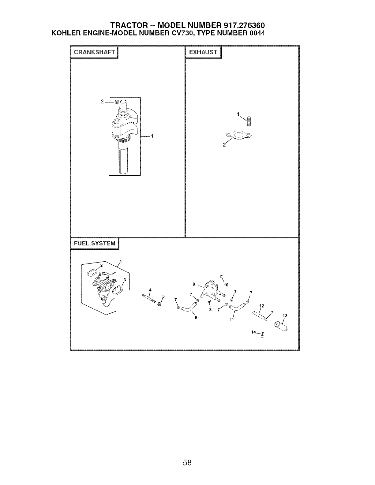
TRACTOR -- MODEL NUMBER 917.276360
KOHLER ENGINE-MODEL NUMBER CV730, TYPE NUMBER 0044
CRANKSHAFT !
FUEL SYSTEI_,/1I
13
144
58

TRACTOR -- MODEL NUMBER 917.276360
KOHLER ENGINE-MODEL NUMBER CV730, TYPE NUMBER 0044
CRANKSHAFT
KEY PART
NO. NO. DESCRIPTION
1. 24-014-72-S Crankshaft (Includes 2)
2. 52-139-09-S Plug, cup
EXHAUST
KEY PART
NO. NO. DESCRIPTION
1. 24-041-49-S Gasket, exhaust (2)
2. 25-072-04-S Stud, M8x1.25x33 (4)
- - 24-522-332 Short Block
- - 24-782-23 Miniblock
- - 24-755-113-S Gasket Set
FUEL SYSTEM
KEY PART
NO. NO. DESCRIPTION
1. 24-853-102-S
2. 24-041-52-S
3. 24041 14-S
4. M-629095-S
5. M-641060-S
6. 25-353-03-S
7. 25-237-14-S
8. 24-086-12-S
9. 24-393-16-S
10. 24-100-01-S
11. 24-353-12-S
12. 15-353-04-S
13. 24-050-10-S
14. 47-154-01-S
NOT ILLUSTRATED
- - 24 234 02-S
- - 24 757 18-S
- - 24 757 19-S
- - 24 757 20-S
- - 24 757 22-S
Kit, carburetor w/gaskets
(Includes 2,3)
Gasket, carburetor
Gasket, air cleaner base
Stud, M6x1.0x95 (2)
Nut, hex. flange M6x1.0 (2)
Line, fuel 14"
Clamp, hose (6)
Screw, hex. cap. M6x1.7x18
(2)
Pump, fuel - pulse
Nut, plastic (2)
Line, fuel 11"
Line, fuel 11-1/2"
Filter, fuel
Clip, cable
Bowl, float
Kit, overhaul
Kit, choke repair
Kit, gasket
Kit, fuel shutdown solenoid
NOTE: All component dimensions given in U,S,
inches 1 inch = 25,4 mm
59

60

61

62

SUGGESTED GUIDE FOR SIGHTING SLOPES FOR SAFE OPERATION
o')
Go
ONLY RIDE UP AND DOWN HILL,
NOT ACROSS HILL
15 DEGREES MAX.
_hb ARNING: To avoid serious injury, operate your tractor up and
down the face of slopes, never across the face. Do not mow
slopes greater than 15 degrees. Make turns gradually to prevent
tipping or loss of control. Exercise extreme caution when
changing direction on slopes.
1, Fotd this page along dotted Nine indicated above,
2. HoNd page before you so that its Neftedge is vertically parallel to a tree
trunk or other upright structure.
3. Sight across the fomd in the direction of hill smope you want to measure.
4. Compare the angle of the fo_d with the emope of the hill.

Your Home
© Sears, Roebuck and Co.
® Registered Trademark / TMTrademark / SMService Mark of Sears, Roebuck and Co.
® Marca Registrada / TMMarca de Fabrics / SMMarca de Servicio de Sears, Roebuck and Co.
MCMarque de commerce / MDMarque ddposde de Sears, Roebuck and Co.
195836 Rev. 1 3.22.05 RD Printed in U.S.A.