Owner's Manual
CRIIFTSMRN°
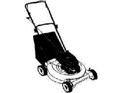
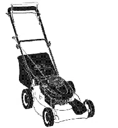
ROTARY LAWN MOWER
6.5 Horsepower
Power-Propelled
21" Multi-Cut
Model No.
917.377841
• Espahol, p. 20
CAUTION:
Read and follow all
Safety Rules and Instructions
before operating this equipment
Sears, Roebuck and Co., Hoffman Estates, IL 60179
Visit our Craftsman website: www.sears.com/craftsman
U.S.A.
Warranty ................................................... 2
Safety Rules .......................................... 2-4
Product Specifications .............................. 4
Assembly / Pre-Operation ..................... 5-6
Operation ............................................ 7-11
Maintenance Schedule ........................... 12
Maintenance ...................................... 12-15
Service and Adjustments ................... 15-17
Storage .............................................. 17-18
Troubleshooting ................................. 18-19
Repair Parts ....................................... 38-47
Sears Service .......................... Back Cover
LIMITED TWO YEAR WARRANTY ON CRAFTSMAN POWER MOWER
For two years from date of purchase, when this Craftsman Lawn Mower is maintained,
lubricated, and tuned up according to the operating and maintenance instructions in the
owner's manual, Sears will repair free of charge any defect in material or workmanship.
If this Craftsman Lawn Mower is used for commercial or rental purposes, this warranty
applies for only 90 days from the date of purchase.
This Warranty does not cover:
• Expendable items which become worn during normal use, such as rotary mower
blades, blade adapters, belts, air cleaners and spark plug.
• Repairs necessary because of operator abuse or negligence, including bent crank-
shafts and the failure to maintain the equipment according to the instructions con-
tained in the owner's manual.
Warranty service is available by returning the Craftsman power mower to the nearest Sears
Parts & Repair Center in the United States. This warranty applies only while this product
is used in the United States.
This Warranty gives you specific legal rights, and you may also have other rights which
vary from state to state.
Sears, Roebuck And Co., D/817 WA, Hoffman Estates, IL 60179
IMPORTANT: This cutting machine is capable of amputating hands and feet and throw-
ing objects. Failure to observe the following safety instructions could result in serious
injury or death.
_¢l,Look for this symbol to point out
important safety precautions. It means
CAUTION!H BECOME ALERT!H
YOUR SAFETY IS INVOLVED.
• I,WARNING: In order to prevent ac-
cidental starting when setting up, trans-
porting, adjusting or making repairs,
always disconnect spark plug wire and
place wire where it cannot come in con-
tact with plug.
A_,WARNING: Engine exhaust, some of its
constituents, and certain vehicle compo-
nents contain or emit chemicals known
to the State of California to cause cancer
and birth defects or other reproductive
harm.
2
Ai_WARNING: Battery posts, terminals and
related accessories contain lead and lead
compounds, chemicals known to the State
of California to cause cancer and birth
defects or other reproductive harm. Wash
hands after handling.
• 1,CAUTION: Muffler and other engine
parts become extremely hot during
operation and remain hot after engine has
stopped. To avoid severe burns on contact,
stay away from these areas.
I. GENERAL OPERATION
• Read, understand, and follow all
instructions on the machine and in the
manual(s) before starting. Be thoroughly
familiar with the controls and the proper
use of the machine before starting.
• Do not put hands or feet near or under
rotating parts. Keep clear of the dis-
charge opening at all times.
• Only allow responsible individuals, who
are familiar with the instructions, to oper-
ate the machine.
• Clear the area of objects such as rocks,
toys, wire, bones, sticks, etc., which
could be picked up and thrown by the
blade.
• Be sure the area is clear of other people
before mowing. Stop machine if anyone
enters the area.
• Do not operate the mower when bare-
foot or wearing open sandals. Always
wear substantial foot wear.
• Do not pull mower backwards unless
absolutely necessary. Always look down
and behind before and while moving
backwards.
• Do not operate the mower without
proper guards, plates, grass catcher or
other safety protective devices in place.
• See manufacturer's instructions for
proper operation and installation of
accessories. Only use accessories ap-
proved by the manufacturer.
• Stop the blade(s) when crossing gravel
drives, walks, or roads.
• Stop the engine (motor) whenever you
leave the equipment, before cleaning the
mower or unclogging the chute.
• Shut the engine (motor) off and wait until
the blade comes to complete stop before
removing grass catcher.
• Mow only in daylight or good artificial
light.
• Do not operate the machine while under
the influence of alcohol or drugs.
• Never operate machine in wet grass.
Always be sure of your footing: keep a
firm hold on the handle and walk; never
run.
• Disengage the self-propelled mech-
anism or drive clutch on mowers so
equipped before starting the engine
(motor).
• If the equipment should start to vibrate
abnormally, stop the engine (motor) and
check immediately for the cause. Vibra-
tion is generally a warning of trouble.
• Always wear safety goggles or safety
glasses with side shields when operating
II. SLOPE OPERATION
Slopes are a major factor related to slip
and fall accidents which can result in
severe injury. All slopes require extra cau-
tion. If you feel uneasy on a slope, do not
mow it.
DO:
• Mow across the face of slopes: never
up and down. Exercise extreme caution
when changing direction on slopes.
• Remove obstacles such as rocks, tree
limbs, etc.
• Watch for holes, ruts, or bumps. Tall
grass can hide obstacles.
DO NOT:
• Do not trim near drop-offs, ditches or
embankments. The operator could lose
footing or balance.
• Do not trim excessively steep slopes.
• Do not mow on wet grass. Reduced foot-
ing could cause slipping.
III. CHILDREN
Tragic accidents can occur if the operator
is not alert to the presence of children.
Children are often attracted to the machine
and the mowing activity. Never assume
that children will remain where you last
saw them.
• Keep children out of the trimming area
and under the watchful care of another
responsible adult.
• Be alert and turn machine off if children
enter the area.
• Before and while walking backwards,
look behind and down for small children.
• Never allow children to operate the ma-
chine.
• Use extra care when approaching blind
corners, shrubs, trees, or other objects
that may obscure vision.
IV. SERVICE
• Use extra care in handling gasoline and
other fuels. They are flammable and
vapors are explosive.
- Use only an approved container.
- Never remove gas cap or add fuel
with the engine running.
Allow engine to cool before refueling.
Do not smoke.
- Never refuel the machine indoors.
- Never store the machine or fuel
container inside where there is an
open flame, such as a water heater.
• Never run a machine inside a closed area.
• Never make adjustments or repairs with
the engine (motor) running. Disconnect the
spark plug wire, and keep the wire away
mower.
3 from the plug to prevent accidental starting.
• Keepnutsandbolts,especiallyblade
attachmentbolts,tightand keepequip-
mentingoodcondition.
• Nevertamperwith safetydevices.Check
theirproperoperationregularly.
• Keep machine free of grass, leaves,or
otherdebrisbuild-up.Cleanoilorfuelspill-
age.Allowmachinetocoolbeforestoring.
• Stopandinspecttheequipmentifyou
strikean object.Repair,if necessary,
beforerestarting.
• Neverattempttomakewheelheightadjust-
mentswhiletheengine(motor)isrunning.
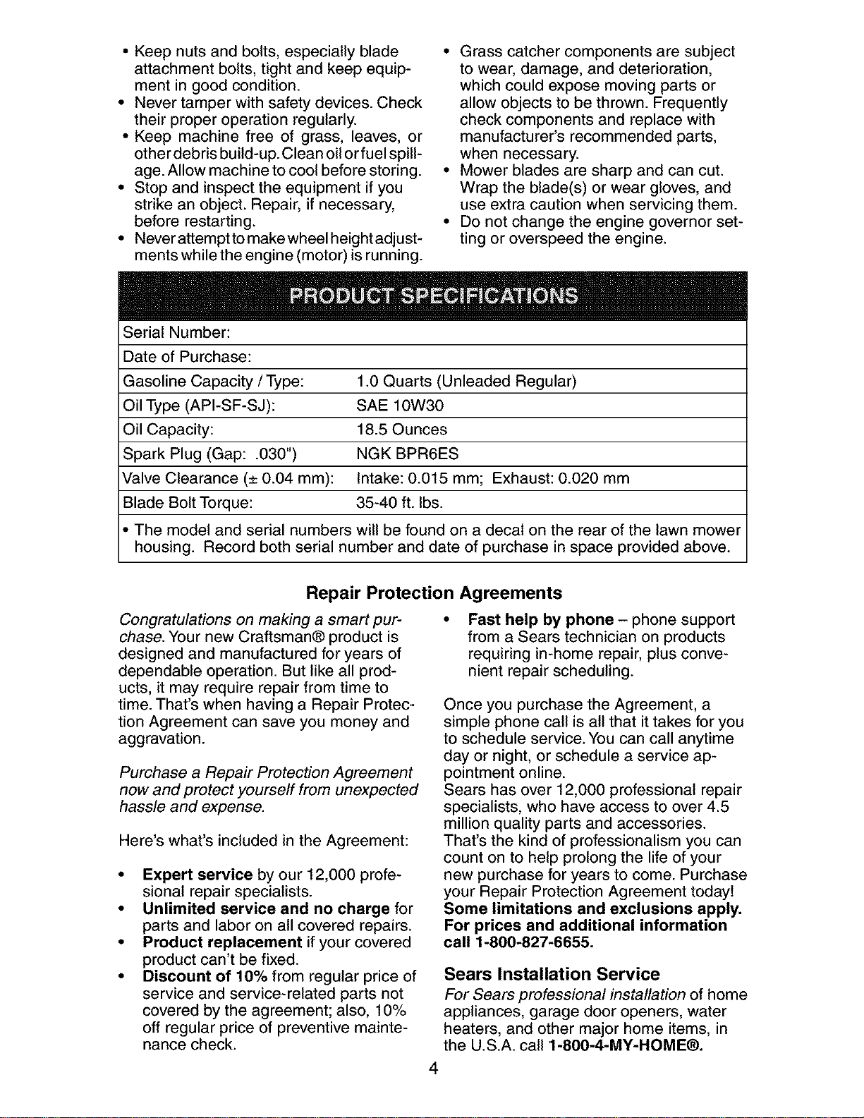
SerialNumber:
• Grasscatchercomponentsaresubject
to wear,damage,anddeterioration,
whichcouldexposemovingpartsor
allowobjectsto be thrown.Frequently
checkcomponentsand replacewith
manufacturer'srecommendedparts,
whennecessary.
• Mowerbladesare sharpandcan cut.
Wraptheblade(s)orweargloves,and
useextracautionwhenservicingthem.
• Donotchangethe enginegovernorset-
ting oroverspeedtheengine.
Dateof Purchase:
GasolineCapacity/Type: 1.0 Quarts (Unleaded Regular)
Oil Type (API-SF-SJ): SAE 10W30
Oil Capacity: 18.5 Ounces
Spark Plug (Gap: .030") NGK BPR6ES
Valve Clearance (± 0.04 mm): Intake: 0.015 mm; Exhaust: 0.020 mm
Blade Bolt Torque: 35-40 ft. Ibs.
• The model and serial numbers will be found on a decal on the rear of the lawn mower
housing. Record both serial number and date of purchase in space provided above.
Repair Protection Agreements
Congratulations on making a smart pur-
chase. Your new Craftsman® product is
designed and manufactured for years of
dependable operation. But like all prod-
ucts, it may require repair from time to
time. That's when having a Repair Protec-
tion Agreement can save you money and
aggravation.
Purchase a Repair Protection Agreement
now and protect yourself from unexpected
hassle and expense.
Here's what's included in the Agreement:
• Expert service by our 12,000 profe-
sional repair specialists.
• Unlimited service and no charge for
parts and labor on all covered repairs.
• Product replacement if your covered
product can't be fixed.
• Discount of 10% from regular price of
service and service-related parts not
covered by the agreement; also, 10%
off regular price of preventive mainte-
nance check.
Fast help by phone - phone support
from a Sears technician on products
requiring in-home repair, plus conve-
nient repair scheduling.
Once you purchase the Agreement, a
simple phone call is all that it takes for you
to schedule service. You can call anytime
day or night, or schedule a service ap-
pointment online.
Sears has over 12,000 professional repair
specialists, who have access to over 4.5
million quality parts and accessories.
That's the kind of professionalism you can
count on to help prolong the life of your
new purchase for years to come. Purchase
your Repair Protection Agreement today!
Some limitations and exclusions apply.
For prices and additional information
call 1-800-827-6655.
Sears Installation Service
For Sears professional installation of home
appliances, garage door openers, water
heaters, and other major home items, in
the U.S.A. call 1-800-4-MY-HOME®.
4
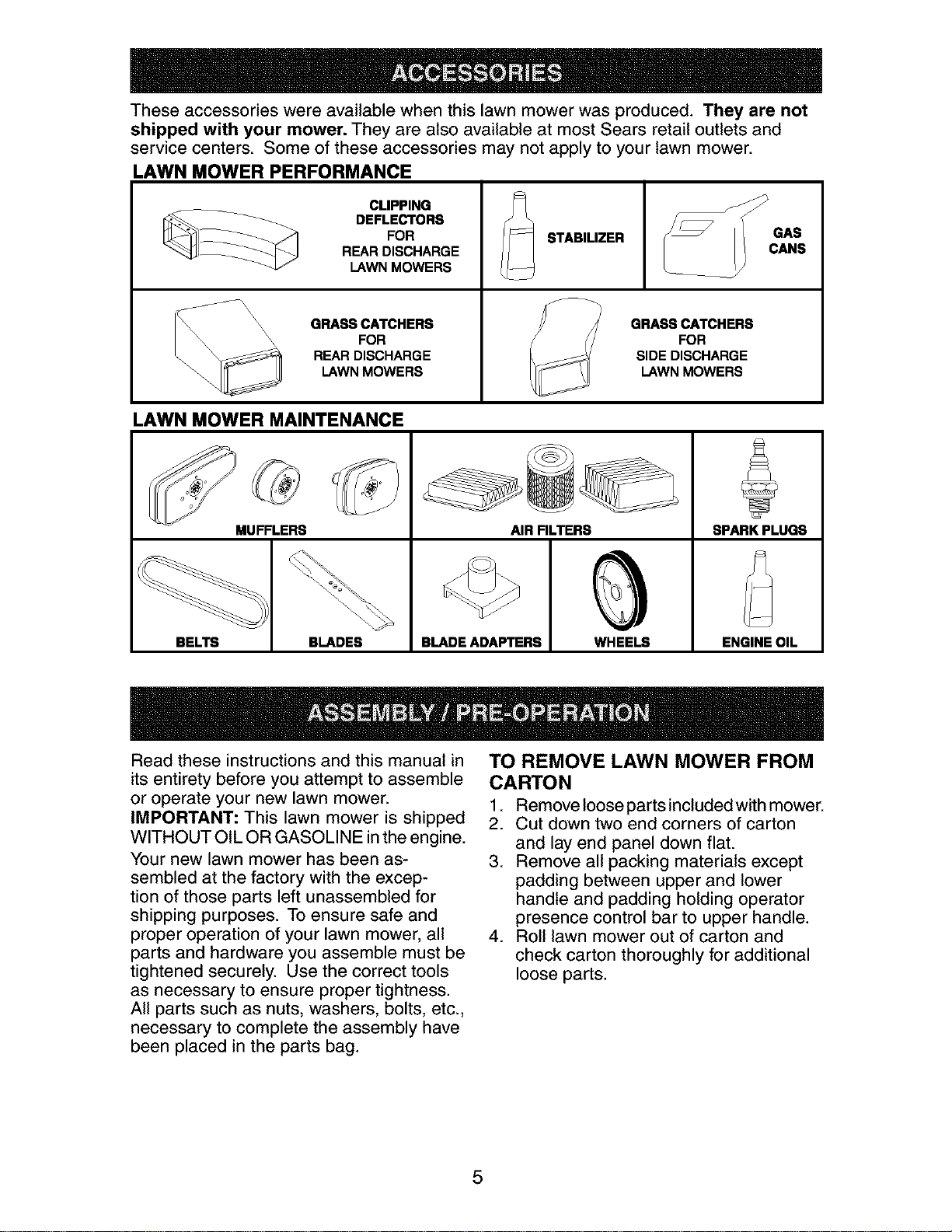
These accessories were available when this lawn mower was produced. They are not
shipped with your mower. They are also available at most Sears retail outlets and
service centers. Some of these accessories may not apply to your lawn mower.
LAWN MOWER PERFORMANCE
CLIPPING
___ DEFLECTORS
FOR STABILIZER
REAR DISCHARGE
LAWN MOWERS
\\ GRASS CATCHERS GRASS CATCHERS
_\\ \\\ FOR FOR
REAR DISCHARGE SIDE DISCHARGE
LAWN MOWERS LAWN MOWERS
LAWN MOWER MAINTENANCE
MUFFLERS
BELTS BLADES
AIR FILTERS
BLADE ADAFq'ERS WHEELS
SPARK PLUGS
ENGINE OIL
Read these instructions and this manual in
its entirety before you attempt to assemble
or operate your new lawn mower.
IMPORTANT: This lawn mower is shipped
WITHOUT OIL OR GASOLINE inthe engine.
Your new lawn mower has been as-
sembled at the factory with the excep-
tion of those parts left unassembled for
shipping purposes. To ensure safe and
proper operation of your lawn mower, all
parts and hardware you assemble must be
tightened securely. Use the correct tools
as necessary to ensure proper tightness.
All parts such as nuts, washers, bolts, etc.,
necessary to complete the assembly have
been placed in the parts bag.
TO REMOVE LAWN MOWER FROM
CARTON
1. Remove loose parts included with mower.
2. Cut down two end corners of carton
and lay end panel down flat.
3. Remove all packing materials except
padding between upper and lower
handle and padding holding operator
presence control bar to upper handle.
4. Roll lawn mower out of carton and
check carton thoroughly for additional
loose parts.
5
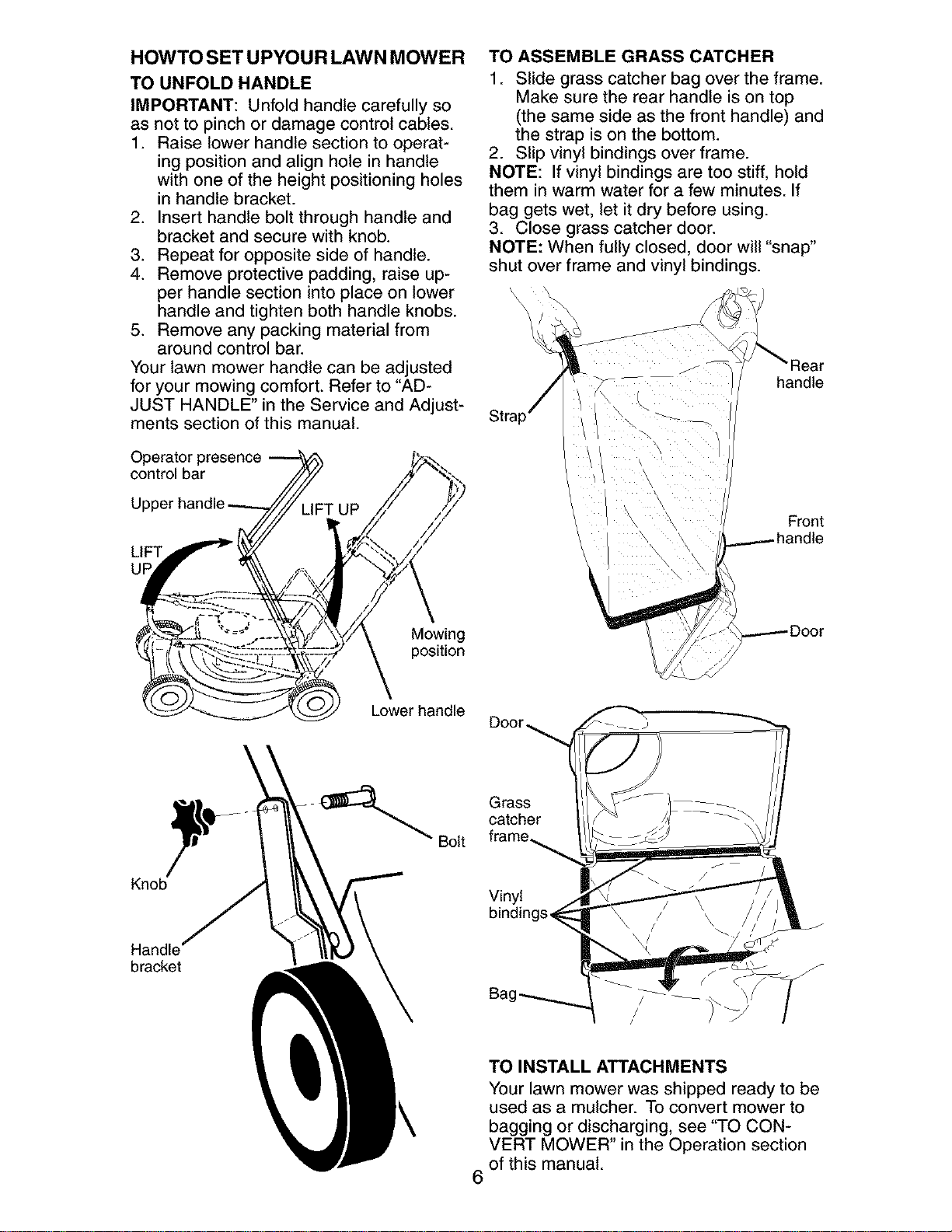
HOWTO SET UPYOUR LAWN MOWER
TO UNFOLD HANDLE
IMPORTANT: Unfold handle carefully so
as not to pinch or damage control cables.
1. Raise lower handle section to operat-
ing position and align hole in handle
with one of the height positioning holes
in handle bracket.
2. Insert handle bolt through handle and
bracket and secure with knob.
3. Repeat for opposite side of handle.
4. Remove protective padding, raise up-
per handle section into place on lower
handle and tighten both handle knobs.
5. Remove any packing material from
around control bar.
Your lawn mower handle can be adjusted
for your mowing comfort. Refer to "AD-
JUST HANDLE" in the Service and Adjust-
ments section of this manual.
Operator presence
control bar
LIFT
UF
Mowing
position
Lower handle
4__ Bolt
Knob
Handle"
bmc_t
TO ASSEMBLE GRASS CATCHER
1. Slide grass catcher bag over the frame.
Make sure the rear handle is on top
(the same side as the front handle) and
the strap is on the bottom.
2. Slip vinyl bindings over frame.
NOTE: If vinyl bindings are too stiff, hold
them in warm water for a few minutes. If
bag gets wet, let it dry before using.
3. Close grass catcher door.
NOTE: When fully closed, door will "snap"
shut over frame and vinyl bindings.
r
J
_Rear
handle
Front
Grass
catcher
Vinyl
6
TO INSTALL ATTACHMENTS
Your lawn mower was shipped ready to be
used as a mulcher. To convert mower to
bagging or discharging, see "TO CON-
VERT MOWER" in the Operation section
of this manual.
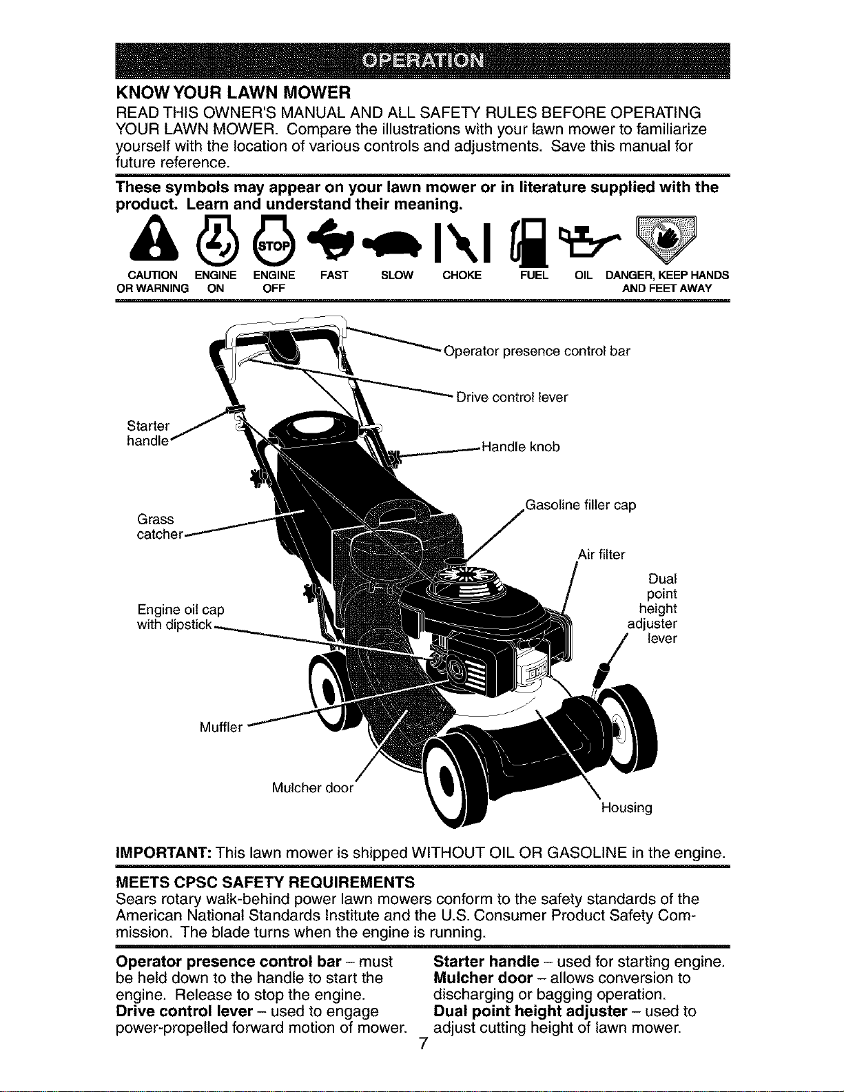
KNOW YOUR LAWN MOWER
READ THIS OWNER'S MANUAL AND ALL SAFETY RULES BEFORE OPERATING
YOUR LAWN MOWER. Compare the illustrations with your lawn mower to familiarize
yourself with the location of various controls and adjustments. Save this manual for
future reference.
These symbols may appear on your lawn mower or in literature supplied with the
product. Learn and understand their meaning.
CAUTION ENGINE ENGINE FAST SLOW CHOKE FUEL OIL DANGER, KEEP HANDS
OR WARNING ON OFF AND FEET AWAY
-Operator presence control bar
Starter
handle
Drive control lever
Grass
catcher
Engine oil cap
with
Gasoline filler cap
Air filter
Dual
point
height
adjuster
lever
Muffler
Mulcher door
Housing
IMPORTANT: This lawn mower is shipped WITHOUT OIL OR GASOLINE in the engine.
MEETS CPSC SAFETY REQUIREMENTS
Sears rotary walk-behind power lawn mowers conform to the safety standards of the
American National Standards Institute and the U.S. Consumer Product Safety Com-
mission. The blade turns when the engine is running.
Operator presence control bar - must
be held down to the handle to start the
engine. Release to stop the engine.
Drive control lever - used to engage
power-propelled forward motion of mower.
7
Starter handle - used for starting engine.
Mulcher door - allows conversion to
discharging or bagging operation.
Dual point height adjuster - used to
adjust cutting height of lawn mower.
Theoperationof any lawn
mowercan resultin foreign
objectsthrownintothe
eyes,whichcan resultin
severeeye damage.Always
wearsafetyglassesor eyeshieldswhile
operatingyourlawnmowerorperforming
any adjustmentsor repairs.We recom-
mendastandardsafetyglassesor wide
visionsafetymaskwornoverspectacles.
HOW TO USE YOUR LAWN MOWER
ENGINE SPEED
The engine speed was set at the factory
for optimum performance. Speed is not
adjustable.
ENGINE ZONE CONTROL
• i,CAUTION: Federal regulations require
an engine control to be installed on this
lawn mower in order to minimize the
risk of blade contact injury. Do not under
any circumstances attempt to defeat the
function of the operator control. The blade
turns when the engine is running.
• Your lawn mower is equipped with an
operator presence control bar which
requires the operator to be positioned
behind the lawn mower handle to start
and operate the lawn mower.
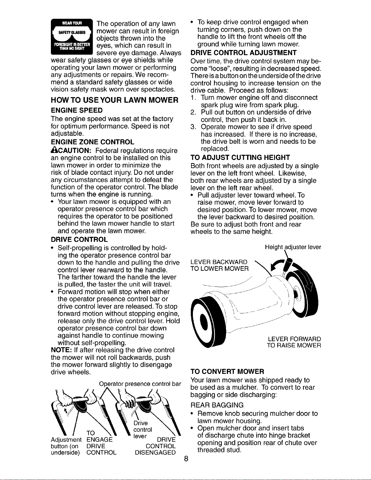
DRIVE CONTROL
• Self-propelling is controlled by hold-
ing the operator presence control bar
down to the handle and pulling the drive
control lever rearward to the handle.
The farther toward the handle the lever
is pulled, the faster the unit will travel.
• Forward motion will stop when either
the operator presence control bar or
drive control lever are released. To stop
forward motion without stopping engine,
release only the drive control lever. Hold
operator presence control bar down
against handle to continue mowing
without self-propelling.
NOTE: If after releasing the drive control
the mower will not roll backwards, push
the mower forward slightly to disengage
drive wheels.
_=ratorpresence control bar
TO
Adjustment ENGAGE
button (on DRIVE
underside) CONTROL
Drive
control
lever
DRIVE
CONTROL
DISENGAGED
• To keep drive control engaged when
turning corners, push down on the
handle to lift the front wheels off the
ground while turning lawn mower.
DRIVE CONTROL ADJUSTMENT
Over time, the drive control system may be-
come "loose", resulting in decreased speed.
There isa button onthe underside ofthe drive
control housing to increase tension on the
drive cable. Proceed as follows:
1. Turn mower engine off and disconnect
spark plug wire from spark plug.
2. Pull out button on underside of drive
control, then push it back in.
3. Operate mower to see if drive speed
has increased. If there is no increase,
the drive belt is worn and needs to be
replaced.
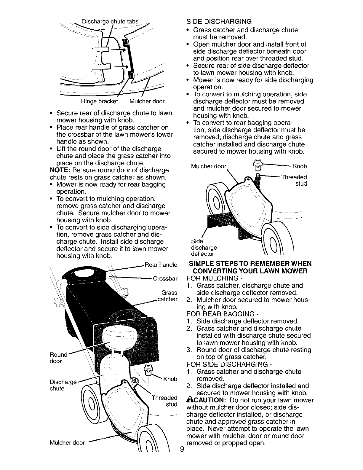
TO ADJUST CUTTING HEIGHT
Both front wheels are adjusted by a single
lever on the left front wheel. Likewise,
both rear wheels are adjusted by a single
lever on the left rear wheel.
• Pull adjuster lever toward wheel. To
raise mower, move lever forward to
desired position. To lower mower, move
the lever backward to desired position.
Be sure to adjust both front and rear
wheels to the same height.
usterlever
LEVER BACKWARD
TO LOWER MOWER
LEVER FORWARD
TO RAISE MOWER
8
TO CONVERT MOWER
Your lawn mower was shipped ready to
be used as a mulcher. To convert to rear
bagging or side discharging:
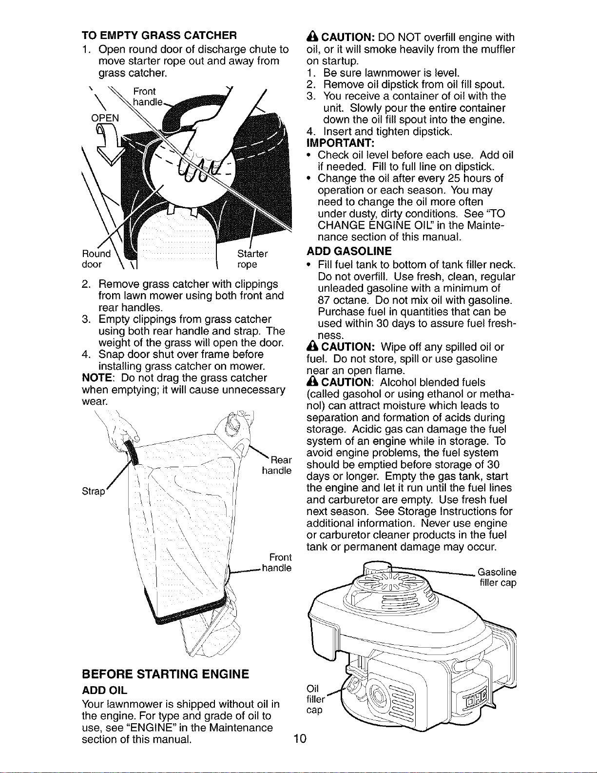
REAR BAGGING
• Remove knob securing mulcher door to
lawn mower housing.
• Open mulcher door and insert tabs
of discharge chute into hinge bracket
opening and position rear of chute over
threaded stud.
. Discharge chute tabss _.
Hinge bracket Mulcher doer
• Secure rear of discharge chute to lawn
mower housing with knob.
• Place rear handle of grass catcher on
the crossbar of the lawn mower's lower
handle as shown.
• Lift the round door of the discharge
chute and place the grass catcher into
place on the discharge chute.
NOTE: Be sure round door of discharge
chute rests on grass catcher as shown.
• Mower is now ready for rear bagging
operation.
• To convert to mulching operation,
remove grass catcher and discharge
chute. Secure mulcher door to mower
housing with knob.
• To convert to side discharging opera-
tion, remove grass catcher and dis-
charge chute. Install side discharge
deflector and secure it to lawn mower
housing with knob.
\
\
\
Grass
door
chute
Threaded
stud
Mulcher door
9
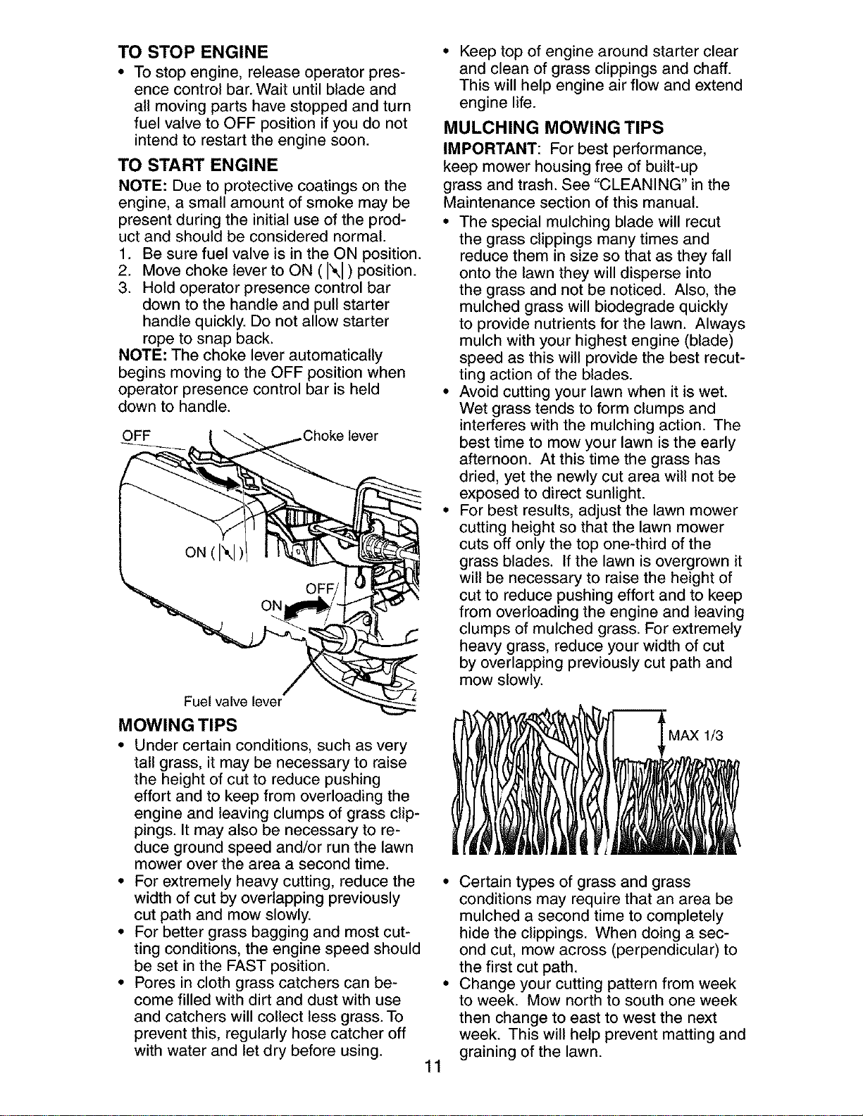
SIDE DISCHARGING
• Grass catcher and discharge chute
must be removed.
• Open mulcher door and install front of
side discharge deflector beneath door
and position rear over threaded stud.
• Secure rear of side discharge deflector
to lawn mower housing with knob.
• Mower is now ready for side discharging
operation.
• To convert to mulching operation, side
discharge deflector must be removed
and mulcher door secured to mower
housing with knob.
• To convert to rear bagging opera-
tion, side discharge deflector must be
removed; discharge chute and grass
catcher installed and discharge chute
secured to mower housing with knob.
Mulcher door - Knob
eaded
stud
Side
discharge
deflector
SIMPLE STEPS TO REMEMBER WHEN
CONVERTING YOUR LAWN MOWER
FOR MULCHING -
1. Grass catcher, discharge chute and
side discharge deflector removed.
2. Mulcher door secured to mower hous-
ing with knob.
FOR REAR BAGGING -
1. Side discharge deflector removed.
2. Grass catcher and discharge chute
installed with discharge chute secured
to lawn mower housing with knob.
3. Round door of discharge chute resting
on top of grass catcher.
FOR SIDE DISCHARGING -
1. Grass catcher and discharge chute
removed.
2. Side discharge deflector installed and
secured to mower housing with knob.
• I_CAUTION: Do not run your lawn mower
without mulcher door closed; side dis-
charge deflector installed, or discharge
chute and approved grass catcher in
place. Never attempt to operate the lawn
mower with mulcher door or round door
removed or propped open.
TO EMPTY GRASS CATCHER
1. Open round door of discharge chute to
move starter rope out and away from
grass catcher.
\ Front
\
OPEN
Round Starter
door rope
2. Remove grass catcher with clippings
from lawn mower using both front and
rear handles.
3. Empty clippings from grass catcher
using both rear handle and strap. The
weight of the grass will open the door.
4. Snap door shut over frame before
installing grass catcher on mower.
NOTE: Do not drag the grass catcher
when emptying; it will cause unnecessary
wear.
handle
Front
BEFORE STARTING ENGINE
ADD OIL
Your lawnmower is shipped without oil in
the engine. For type and grade of oil to
use, see "ENGINE" in the Maintenance
section of this manual.
A CAUTION: DO NOT overfill engine with
oil, or it will smoke heavily from the muffler
on startup.
1. Be sure lawnmower is level.
2. Remove oil dipstick from oil fill spout.
3. You receive a container of oil with the
unit. Slowly pour the entire container
down the oil fill spout into the engine.
4. Insert and tighten dipstick.
IMPORTANT:
• Check oil level before each use. Add oil
if needed. Fill to full line on dipstick.
• Change the oil after every 25 hours of
operation or each season. You may
need to change the oil more often
under dusty, dirty conditions. See "TO
CHANGE ENGINE OIL' in the Mainte-
nance section of this manual.
ADD GASOLINE
• Fill fuel tank to bottom of tank filler neck.
Do not overfill. Use fresh, clean, regular
unleaded gasoline with a minimum of
87 octane. Do not mix oil with gasoline.
Purchase fuel in quantities that can be
used within 30 days to assure fuel fresh-
Bess.
A CAUTION: Wipe off any spilled oil or
fuel. Do not store, spill or use gasoline
near an open flame.
CAUTION: Alcohol blended fuels
(called gasohol or using ethanol or metha-
nol) can attract moisture which leads to
separation and formation of acids during
storage. Acidic gas can damage the fuel
system of an engine while in storage. To
avoid engine problems, the fuel system
should be emptied before storage of 30
days or longer. Empty the gas tank, start
the engine and let it run until the fuel lines
and carburetor are empty. Use fresh fuel
next season. See Storage Instructions for
additional information. Never use engine
or carburetor cleaner products in the fuel
tank or permanent damage may occur.
Gasoline
filler cap
Oil
cap
10
TO STOP ENGINE
• To stop engine, release operator pres-
ence control bar. Wait until blade and
all moving parts have stopped and turn
fuel valve to OFF position if you do not
intend to restart the engine soon.
TO START ENGINE
NOTE: Due to protective coatings on the
engine, a small amount of smoke may be
present during the initial use of the prod-
uct and should be considered normal.
1. Be sure fuel valve is in the ON position.
2. Move choke lever to ON ( I\1 ) position.
3. Hold operator presence control bar
down to the handle and pull starter
handle quickly. Do not allow starter
rope to snap back.
NOTE: The choke lever automatically
begins moving to the OFF position when
operator presence control bar is held
down to handle.
OFF .Choke lever
Fuel valve lever
MOWING TIPS
• Under certain conditions, such as very
tall grass, it may be necessary to raise
the height of cut to reduce pushing
effort and to keep from overloading the
engine and leaving clumps of grass clip-
pings. It may also be necessary to re-
duce ground speed and/or run the lawn
mower over the area a second time.
• For extremely heavy cutting_ reduce the
width of cut by overlapping previously
cut path and mow slowly.
• For better grass bagging and most cut-
ting conditions, the engine speed should
be set in the FAST position.
• Pores in cloth grass catchers can be-
come filled with dirt and dust with use
and catchers will collect less grass. To
prevent this, regularly hose catcher off
with water and let dry before using.
• Keep top of engine around starter clear
and clean of grass clippings and chaff.
This will help engine air flow and extend
engine life.
MULCHING MOWING TIPS
IMPORTANT: For best performance,
keep mower housing free of built-up
grass and trash. See "CLEANING" in the
Maintenance section of this manual.
• The special mulching blade will recut
the grass clippings many times and
reduce them in size so that as they fall
onto the lawn they will disperse into
the grass and not be noticed. Also, the
mulched grass will biodegrade quickly
to provide nutrients for the lawn. Always
mulch with your highest engine (blade)
speed as this will provide the best recut-
ting action of the blades.
• Avoid cutting your lawn when it is wet.
Wet grass tends to form clumps and
interferes with the mulching action. The
best time to mow your lawn is the early
afternoon. At this time the grass has
dried, yet the newly cut area will not be
exposed to direct sunlight.
• For best results, adjust the lawn mower
cutting height so that the lawn mower
cuts off only the top one-third of the
grass blades. If the lawn is overgrown it
wil_ be necessary to raise the height of
cut to reduce pushing effort and to keep
from overloading the engine and leaving
clumps of mulched grass. For extremely
heavy grass, reduce your width of cut
by overlapping previously cut path and
mow slowly.
MAX 1/3
11
• Certain types of grass and grass
conditions may require that an area be
mulched a second time to completely
hide the clippings. When doing a sec-
ond cut, mow across (perpendicular) to
the first cut path.
• Change your cutting pattern from week
to week. Mow north to south one week
then change to east to west the next
week. This will help prevent matting and
graining of the lawn.
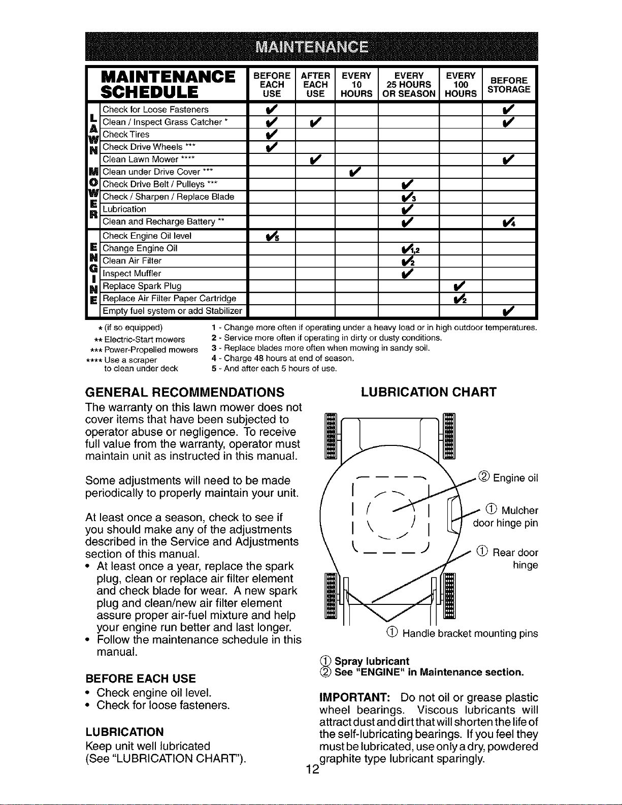
MAINTENANCE BEFOREAPTEREVERY EVERY EVERYBEFORE
EACH EACH 10 25HOURS 100
SCHEDULE USE USE HOURS ORSEASON HOURS STORAGE
Check for Loose Fasteners
_ Clean / Inspect Grass Catcher *
Check Tires
_ Check Drive Wheels
Clean Lawn Mower ....
M Clean under Drive Cover ***
O Check Drive Belt / Pulleys ***
_ Check / Sharpen / Replace Blade
R Lubrication
Clean and Recharge Battery **
Check Engine Oil level
E Change Engine Oil
_ Clean Air Filter
Inspect Muffler
_ Replace Spark Plug
E Replace Air Filter Paper Cartridge
Empty fuel system or add Stabilizer
t_,2
* (if so equipped)
** Electric-Start mowers
*** Power-Propelled mowers
**** Use a scraper
to clean under deck
1 - Change more often if operating under a heavy load or in high outdoor temperatures.
2 - Service more often if operating in dirty or dusty conditions.
3 - Replace blades more often when mowing in sandy soil.
4 - Charge 48 hours at end of season.
5 - And after each 5 hours of use.
GENERAL RECOMMENDATIONS
The warranty on this lawn mower does not
cover items that have been subjected to
operator abuse or negligence. To receive
full value from the warranty, operator must
maintain unit as instructed in this manual.
LUBRICATION CHART
Some adjustments will need to be made
periodically to properly maintain your unit.
At least once a season, check to see if
you should make any of the adjustments
described in the Service and Adjustments
section of this manual.
• At least once a year, replace the spark
plug, clean or replace air filter element
and check blade for wear. A new spark
plug and clean/new air filter element
assure proper air-fuel mixture and help
your engine run better and last longer.
• Follow the maintenance schedule in this
manual.
BEFORE EACH USE
• Check engine oil level.
• Check for loose fasteners.
LUBRICATION
Keep unit well lubricated
(See "LUBRICATION CHART').
ine oil
(_) Mulcher
door hinge pin
(_ Rear door
hinge
(_ Handle bracket mounting pins
_ Spray lubricant
See "ENGINE" in Maintenance section.
IMPORTANT: Do not oil or grease plastic
wheel bearings. Viscous lubricants will
attract dust and dirt that will shorten the life of
the self-lubricating bearings. If you feel they
must be lubricated, use only a dry, powdered
2graphite type lubricant sparingly.
1
LAWN MOWER
Always observe safety rules when per-
forming any maintenance.
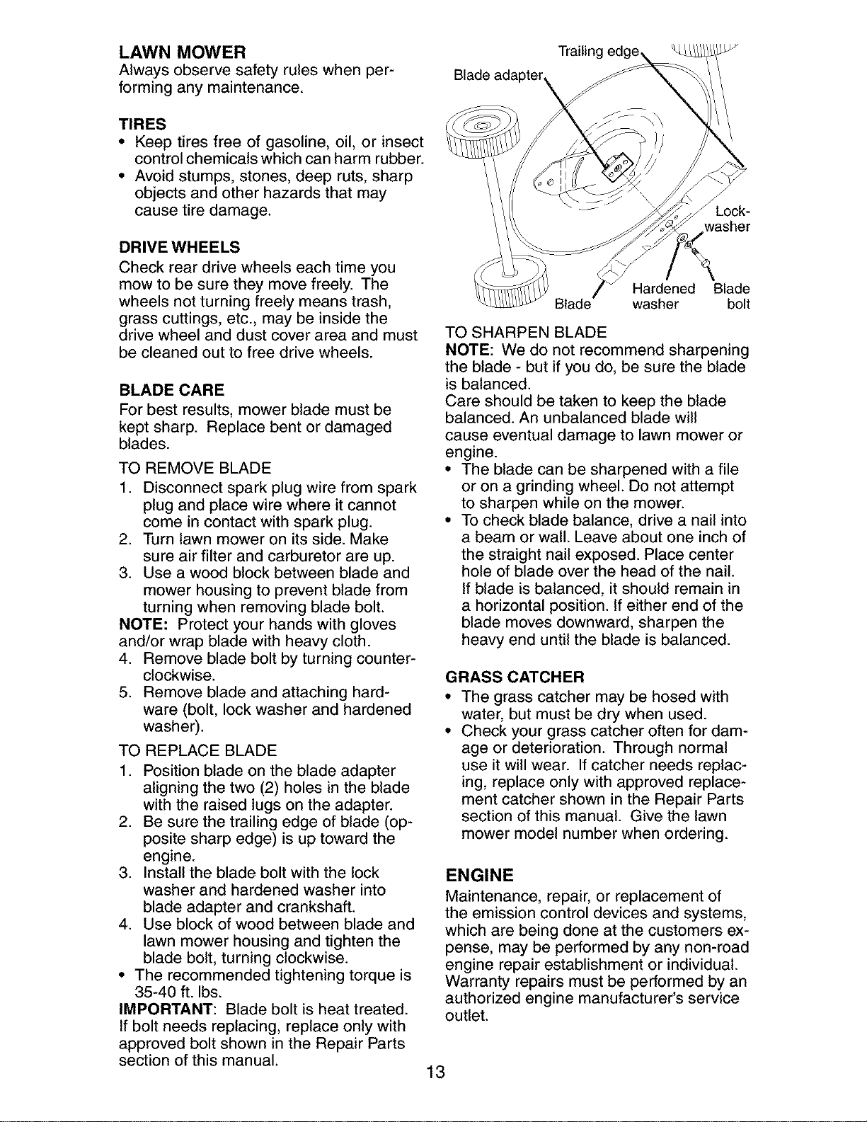
Trailin
Blade adapter
TIRES
• Keep tires free of gasoline, oil, or insect
control chemicals which can harm rubber.
• Avoid stumps, stones, deep ruts, sharp
objects and other hazards that may
cause tire damage.
DRIVE WHEELS
Check rear drive wheels each time you
mow to be sure they move freely. The
wheels not turning freely means trash,
grass cuttings, etc., may be inside the
drive wheel and dust cover area and must
be cleaned out to free drive wheels.
BLADE CARE
For best results, mower blade must be
kept sharp. Replace bent or damaged
blades.
TO REMOVE BLADE
1. Disconnect spark plug wire from spark
plug and place wire where it cannot
come in contact with spark plug.
2. Turn lawn mower on its side. Make
sure air filter and carburetor are up.
3. Use a wood block between blade and
mower housing to prevent blade from
turning when removing blade bolt.
NOTE: Protect your hands with gloves
and/or wrap blade with heavy cloth.
4. Remove blade bolt by turning counter-
clockwise.
5. Remove blade and attaching hard-
ware (bolt, lock washer and hardened
washer).
TO REPLACE BLADE
1. Position blade on the blade adapter
aligning the two (2) holes in the blade
with the raised lugs on the adapter.
2. Be sure the trailing edge of blade (op-
posite sharp edge) is up toward the
engine.
3. Install the blade bolt with the lock
washer and hardened washer into
blade adapter and crankshaft.
4. Use block of wood between blade and
lawn mower housing and tighten the
blade bolt, turning clockwise.
• The recommended tightening torque is
35-40 ft. Ibs.
IMPORTANT: Blade bolt is heat treated.
If bolt needs replacing, replace only with
approved bolt shown in the Repair Parts
section of this manual.
Lock-
washer
Hardened Blade
Blade washer bolt
TO SHARPEN BLADE
NOTE: We do not recommend sharpening
the blade - but if you do, be sure the blade
is balanced.
Care should be taken to keep the blade
balanced. An unbalanced blade will
cause eventual damage to lawn mower or
engine.
• The blade can be sharpened with a file
or on a grinding wheel. Do not attempt
to sharpen while on the mower.
• To check blade balance, drive a nail into
a beam or wall. Leave about one inch of
the straight nail exposed. Place center
hole of blade over the head of the nail.
If blade is balanced, it should remain in
a horizontal position. If either end of the
blade moves downward, sharpen the
heavy end until the blade is balanced.
GRASS CATCHER
• The grass catcher may be hosed with
water, but must be dry when used.
• Check your grass catcher often for dam-
age or deterioration. Through normal
use it will wear. If catcher needs replac-
ing, replace only with approved replace-
ment catcher shown in the Repair Parts
section of this manual. Give the lawn
mower model number when ordering.
ENGINE
Maintenance, repair, or replacement of
the emission control devices and systems,
which are being done at the customers ex-
pense, may be performed by any non-road
engine repair establishment or individual.
Warranty repairs must be performed by an
authorized engine manufacturer's service
outlet.
13
LUBRICATION
Use only high quality detergent oil rated
with API service classification SF-SJ.
Select the oil's SAE viscosity grade
according to your expected operating
temperature.
SAE VISCOSITY GRADES
'F _0 0 30 32 40 80 80 100
'c _ _ -lo o lo 2o
TEMPERA'RJRE RANGE ANTICIPATED BEFORE NEXT OIL CHANGE
NOTE: Multi-viscosity oils (5W30, 10W30
etc.) improve starting in cold weather, and
you should check your engine oil level fre-
quently to avoid possible engine damage
from running low on oil.
Change the oil after every 25 hours of opera-
tion or at least once a year ifthe lawn mower
is not used for 25 hours in one year.
Check the crankcase oil level before
starting the engine and after each five (5)
hours of continuous use. Tighten oil plug
securely each time you check the oil level.
TO CHANGE ENGINE OIL
NOTE: Before tipping lawn mower to drain
oil, empty fuel tank by running engine until
fuel tank is empty.
1. Disconnect spark plug wire from spark
plug and place wire where it cannot
come in contact with plug.
2. Remove engine oil cap; lay aside on a
clean surface.
3. Tip lawn mower on its side as shown
and drain oil into a suitable container.
Rock lawn mower back and forth to re-
move any oil trapped inside of engine.
4. Wipe off any spilled oil from lawn
mower or side of engine.
5. Fillengine with oil. The engine oil capacity
is 18.5 oz. If oil is not completely drained
from engine, you may not need the entire
container of a 20 oz. bottle of oil. Slowly
pour 3/4 of the oil from the container down
the oil fill spout into the engine.
6. Wait one minute to allow oil to settle.
Use guage on oil fill cap/dipstick for
checking level. Insert dipstick into the
tube and rest the oil fill cap on the tube.
DO NOT thread the cap into the tube
when taking reading.
7. Continue adding small amounts of
oil and rechecking the dipstick until it
reads full. DO NOT overfill, or engine
will smoke on startup.
8. Always be sure to retighten oil dipstick
before starting engine.
9. Reconnect spark plug wire to plug.
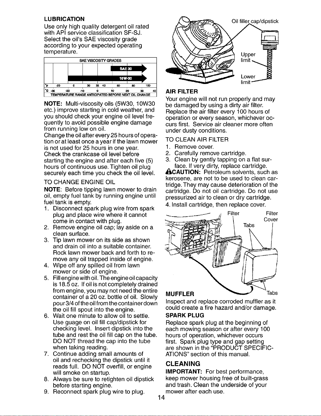
Oil filler cap/dipstick
AIR FILTER
limit
Your engine will not run properly and may
be damaged by using a dirty air filter.
Replace the air filter every 100 hours of
operation or every season, whichever oc-
curs first. Service air cleaner more often
under dusty conditions.
TO CLEAN AIR FILTER
1. Remove cover.
2. Carefully remove cartridge.
3. Clean by gently tapping on a flat sur-
face. If very dirty, replace cartridge.
AqLCAUTION: Petroleum solvents, such as
kerosene, are not to be used to clean car-
tridge. They may cause deterioration of the
cartridge. Do not oil cartridge. Do not use
pressurized air to clean or dry cartridge.
4. Install cartridge, then replace cover.
Filter Filter
Cover
Tabs
MUFFLER Tabs
Inspect and replace corroded muffler as it
could create a fire hazard and/or damage.
SPARK PLUG
Replace spark plug at the beginning of
each mowing season or after every 100
hours of operation, whichever occurs
first. Spark plug type and gap setting
are shown in the "PRODUCT SPECIFIC-
ATIONS" section of this manual.
CLEANING
IMPORTANT: For best performance,
keep mower housing free of built-grass
and trash. Clean the underside of your
mower after each use.
14
_i,CAUTION: Disconnect spark plug wire
from spark plug and place wire where it
cannot come in contact with plug.
• Clean the underside of your lawn mower
by scraping to remove build-up of grass
and trash.
• Clean engine often to keep trash from
accumulating. A clogged engine runs
hotter and shortens engine life.
• Keep finished surfaces and wheels free
of all gasoline, oil, etc.
• We do not recommend using a garden
hose to clean lawn mower unless the
electrical system, muffler, air filter and
carburetor are covered to keep water
out. Water in engine can result in short-
ened engine life.
CLEAN UNDER DRIVE COVER
Clean under drive cover at least twice a sea-
son. Scrape underside of cover with putty
knife or similar tool to remove any build-up
of trash or grass on underside of drive cover.
_WARNING: To avoid serious injury, before
performing any service and adjustments:
1. Release control bar and stop engine.
2. Make sure the blade and all moving
parts have completely stopped.
3. Disconnect spark plug wire from spark
plug and place wire where it cannot
come in contact with plug.
LAWN MOWER
TO ADJUST CUTTING HEIGHT
See "TO ADJUST CUTTING HEIGHT' in
the Operation section of this manual.
REAR DEFLECTOR
The rear deflector, attached between the
rear wheels of your mower, is provided to
minimize the possibility that objects will be
thrown out of the rear of the mower into
the operator mowing position. If deflector
becomes damaged, it should be replaced.
TO REMOVE DRIVE BELT
1. Disconnect spark plug wire from spark
plug and place wire where it cannot
come in contact with plug.
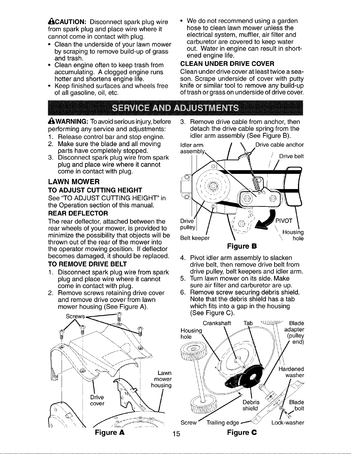
2. Remove screws retaining drive cover
and remove drive cover from lawn
mower housing (See Figure A).
Screws_
3. Remove drive cable from anchor, then
detach the drive cable spring from the
idler arm assembly (See Figure B).
Idler arm Drive cable anchor
Drive belt
pulley
Belt keeper
PIVOT
\ Housing
\ hole
Figure B
4. Pivot idler arm assembly to slacken
drive belt, then remove drive belt from
drive pulley, belt keepers and idler arm.
5. Turn lawn mower on its side. Make
sure air filter and carburetor are up.
6. Remove screw securing debris shield.
Note that the debris shield has a tab
which fits into a gap in the housing
(See Figure C).
Crankshaft Tab _ Blade
Housing adapter
hole (pulley
end)
Drive
cover
Lawn
mower
housing
Figure A 15
Trailing edge
Figure C
Hardened
washer
Blade
bolt
Lock-washer
7. Use a wood block between blade and
mower housing to prevent blade from
turning when removing blade bolt.
NOTE: Protect your hands with gloves
and/or wrap blade with heavy cloth.
8. Remove blade bolt.
9. Remove blade, attaching hardware
(bolt, lock washer and hardened wash-
er), blade adapter and debris shield as
one assembly.
10. Remove drive belt from blade adapter
and debris shield; discard old belt.
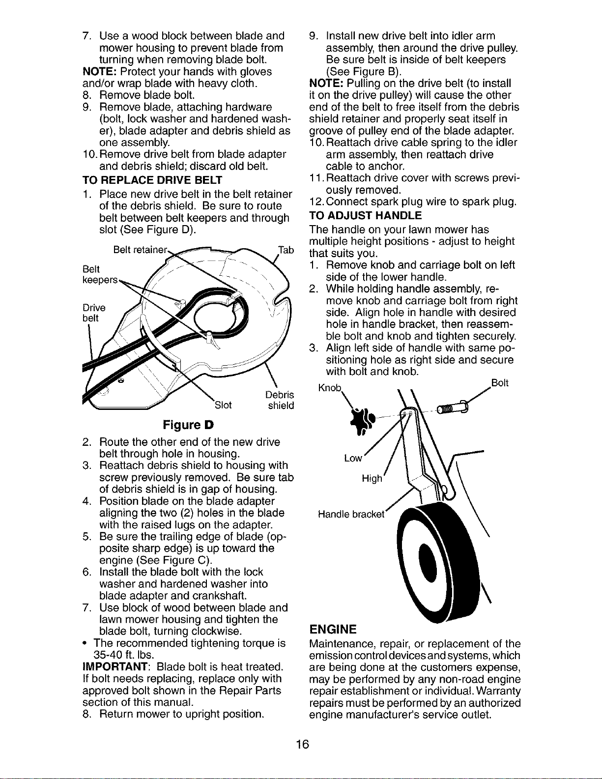
TO REPLACE DRIVE BELT
Place new drive belt in the belt retainer
of the debris shield. Be sure to route
belt between belt keepers and through
slot (See Figure D).
Belt retainer, Tab
Belt
Drive
belt
Debris
Slot shield
Figure D
2. Route the other end of the new drive
belt through hole in housing.
3. Reattach debris shield to housing with
screw previously removed. Be sure tab
of debris shield is in gap of housing.
4. Position blade on the blade adapter
aligning the two (2) holes in the blade
with the raised lugs on the adapter.
5. Be sure the trailing edge of blade (op-
posite sharp edge) is up toward the
engine (See Figure C).
6. Install the blade bolt with the lock
washer and hardened washer into
blade adapter and crankshaft.
7. Use block of wood between blade and
lawn mower housing and tighten the
blade bolt, turning clockwise.
• The recommended tightening torque is
35-40 ft. Ibs.
IMPORTANT: Blade bolt is heat treated.
If bolt needs replacing, replace only with
approved bolt shown in the Repair Parts
section of this manual.
8. Return mower to upright position.
9. Install new drive belt into idler arm
assembly, then around the drive pulley.
Be sure belt is inside of belt keepers
(See Figure B).
NOTE: Pulling on the drive belt (to install
it on the drive pulley) will cause the other
end of the belt to free itself from the debris
shield retainer and properly seat itself in
groove of pulley end of the blade adapter.
10.Reattach drive cable spring to the idler
arm assembly, then reattach drive
cable to anchor.
11.Reattach drive cover with screws previ-
ously removed.
12.Connect spark plug wire to spark plug.
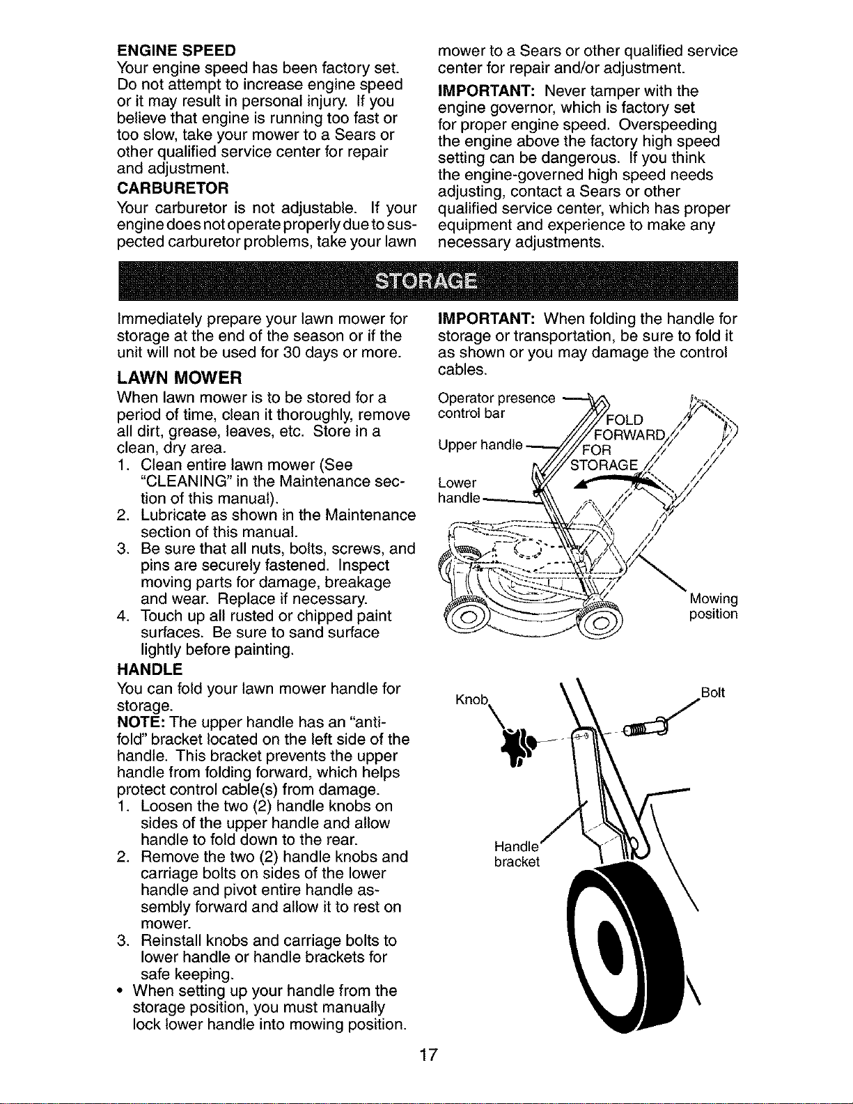
TO ADJUST HANDLE
The handle on your lawn mower has
multiple height positions - adjust to height
that suits you.
1. Remove knob and carriage bolt on left
side of the lower handle.
2. While holding handle assembly, re-
move knob and carriage bolt from right
side. Align hole in handle with desired
hole in handle bracket, then reassem-
ble bolt and knob and tighten securely.
3. Align left side of handle with same po-
sitioning hole as right side and secure
with bolt and knob.
Bolt
Knob_
Hi
ENGINE
Maintenance, repair, or replacement of the
emission control devices and systems, which
are being done at the customers expense,
may be performed by any non-road engine
repair establishment or individual. Warranty
repairs must be performed by an authorized
engine manufacturer's service outlet.
16
ENGINE SPEED
Your engine speed has been factory set.
Do not attempt to increase engine speed
or it may result in personal injury. If you
believe that engine is running too fast or
too slow, take your mower to a Sears or
other qualified service center for repair
and adjustment.
CARBURETOR
Your carburetor is not adjustable. If your
engine does not operate properly due to sus-
pected carburetor problems, take your lawn
mower to a Sears or other qualified service
center for repair and/or adjustment.
IMPORTANT: Never tamper with the
engine governor, which is factory set
for proper engine speed. Overspeeding
the engine above the factory high speed
setting can be dangerous. If you think
the engine-governed high speed needs
adjusting, contact a Sears or other
qualified service center, which has proper
equipment and experience to make any
necessary adjustments.
Immediately prepare your lawn mower for
storage at the end of the season or if the
unit will not be used for 30 days or more.
LAWN MOWER
When lawn mower is to be stored for a
period of time, clean it thoroughly, remove
all dirt, grease, leaves, etc. Store in a
clean, dry area.
1. Clean entire lawn mower (See
"CLEANING" in the Maintenance sec-
tion of this manual).
2. Lubricate as shown in the Maintenance
section of this manual.
3. Be sure that all nuts, bolts, screws, and
pins are securely fastened. Inspect
moving parts for damage, breakage
and wear. Replace if necessary.
4. Touch up all rusted or chipped paint
surfaces. Be sure to sand surface
lightly before painting.
HANDLE
You can fold your lawn mower handle for
storage.
NOTE: The upper handle has an "anti-
fold" bracket located on the left side of the
handle. This bracket prevents the upper
handle from folding forward, which helps
protect control cable(s) from damage.
1. Loosen the two (2) handle knobs on
sides of the upper handle and allow
handle to fold down to the rear.
2. Remove the two (2) handle knobs and
carriage bolts on sides of the lower
handle and pivot entire handle as-
sembly forward and allow it to rest on
mower.
3. Reinstall knobs and carriage bolts to
lower handle or handle brackets for
safe keeping.
• When setting up your handle from the
storage position, you must manually
lock lower handle into mowing position.
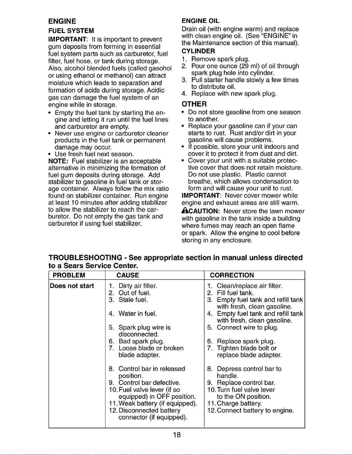
IMPORTANT: When folding the handle for
storage or transportation, be sure to fold it
as shown or you may damage the control
cables.
Operator presence
control bar
Lower
Mowing
position
Knob_
Bolt
Handle'
bracket
17
ENGINE
FUEL SYSTEM
IMPORTANT: It is important to prevent
gum deposits from forming in essential
fuel system parts such as carburetor, fuel
filter, fuel hose, or tank during storage.
Also, alcohol blended fuels (called gasohol
or using ethanol or methanol) can attract
moisture which leads to separation and
formation of acids during storage. Acidic
gas can damage the fuel system of an
engine while in storage.
• Empty the fuel tank by starting the en-
gine and letting it run until the fuel lines
and carburetor are empty.
• Never use engine or carburetor cleaner
products in the fuel tank or permanent
damage may occur.
• Use fresh fuel next season.
NOTE: Fuel stabilizer is an acceptable
alternative in minimizing the formation of
fuel gum deposits during storage. Add
stabilizer to gasoline in fuel tank or stor-
age container. Always follow the mix ratio
found on stabilizer container. Run engine
at least 10 minutes after adding stabilizer
to allow the stabilizer to reach the car-
buretor. Do not empty the gas tank and
carburetor if using fuel stabilizer.
ENGINE OIL
Drain oil (with engine warm) and replace
with clean engine oil. (See "ENGINE" in
the Maintenance section of this manual).
CYLINDER
1. Remove spark plug.
2. Pour one ounce (29 ml) of oil through
spark plug hole into cylinder.
3. Pull starter handle slowly a few times
to distribute oil.
4. Replace with new spark plug.
OTHER
• Do not store gasoline from one season
to another.
• Replace your gasoline can if your can
starts to rust. Rust and/or dirt in your
gasoline will cause problems.
• If possible, store your unit indoors and
cover it to protect it from dust and dirt.
• Cover your unit with a suitable protec-
tive cover that does not retain moisture.
Do not use plastic. Plastic cannot
breathe, which allows condensation to
form and will cause your unit to rust.
IMPORTANT: Never cover mower while
engine and exhaust areas are still warm.
• I,CAUTION: Never store the lawn mower
with gasoline in the tank inside a building
where fumes may reach an open flame
or spark. Allow the engine to cool before
storing in any enclosure.
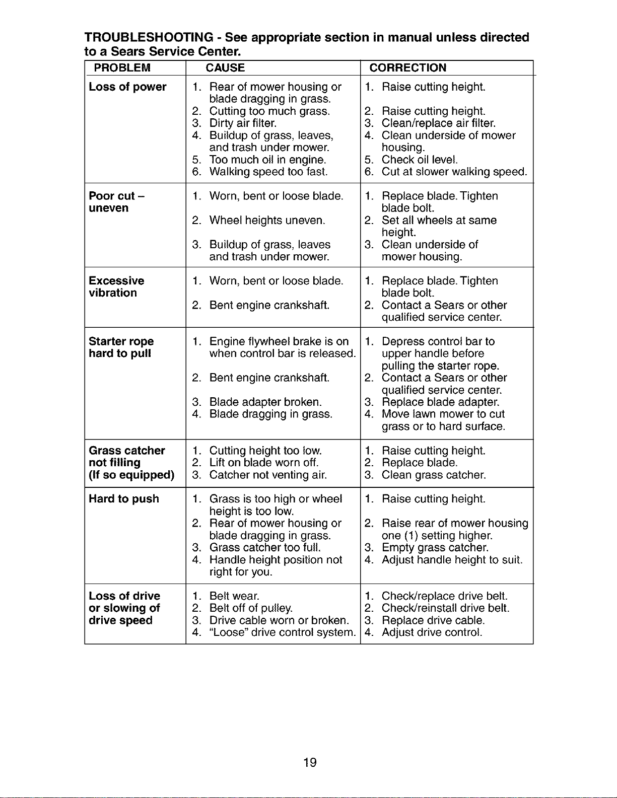
TROUBLESHOOTING - See appropriate section in manual unless directed
to a Sears Service Center.
PROBLEM CAUSE CORRECTION
Does not start
1. Dirty air filter.
2. Out of fuel.
3. Stale fuel.
4. Water in fuel.
5. Spark plug wire is
disconnected.
6. Bad spark plug.
7. Loose blade or broken
blade adapter.
8. Control bar in released
position.
9. Control bar defective.
10. Fuel valve lever (if so
equipped) in OFF position.
11.Weak battery (if equipped).
12. Disconnected battery
connector (if equipped).
2.
3.
4.
5.
6.
7.
Clean/replace air filter.
Fill fuel tank.
Empty fuel tank and refill tank
with fresh, clean gasoline.
Empty fuel tank and refill tank
with fresh, clean gasoline.
Connect wire to plug.
Replace spark plug.
Tighten blade bolt or
replace blade adapter.
8. Depress control bar to
handle.
9. Replace control bar.
10.Turn fuel valve lever
to the ON position.
11.Charge battery.
12.Connect battery to engine.
18
TROUBLESHOOTING - See appropriate section in manual unless directed
to a Sears Service Center.
PROBLEM CAUSE
Loss of power 1. Rear of mower housing or
Poor cut -
uneven
Excessive
vibration
Starter rope
hard to pull
CORRECTION
1. Raise cutting height.
2. Raise cutting height.
3. Clean/replace air filter.
4. Clean underside of mower
housing.
5. Check oil level.
6. Cut at slower walking speed.
blade dragging in grass.
2. Cutting too much grass.
3. Dirty air filter.
4. Buildup of grass, leaves,
and trash under mower.
5. Too much oil in engine.
6. Walking speed too fast.
1. Worn, bent or loose blade.
2. Wheel heights uneven.
3. Buildup of grass, leaves
and trash under mower.
1. Worn, bent or loose blade.
2. Bent engine crankshaft.
1. Engine flywheel brake is on
when control bar is released.
2. Bent engine crankshaft.
3. Blade adapter broken.
4. Blade dragging in grass.
1. Cutting height too low.
2. Lift on blade worn off.
3. Catcher not venting air.
1. Grass is too high or wheel
height is too low.
2. Rear of mower housing or
blade dragging in grass.
3. Grass catcher too full.
4. Handle height position not
right for you.
1. Belt wear.
2. Belt off of pulley.
3. Drive cable worn or broken.
4. "Loose" drive control system.
1. Replace blade. Tighten
blade bolt.
2. Set all wheels at same
height.
3. Clean underside of
mower housing.
1. Replace blade. Tighten
blade bolt.
2. Contact a Sears or other
qualified service center.
1. Depress control bar to
upper handle before
pulling the starter rope.
2. Contact a Sears or other
qualified service center.
3. Replace blade adapter.
4. Move lawn mower to cut
grass or to hard surface.
Grass catcher 1. Raise cutting height.
not filling 2. Replace blade.
(If so equipped) 3. Clean grass catcher.
Hard to push 1. Raise cutting height.
Loss of drive
or slowing of
drive speed
2. Raise rear of mower housing
one (1) setting higher.
3. Empty grass catcher.
4. Adjust handle height to suit.
1. Check/replace drive belt.
2. Check/reinstall drive belt.
3. Replace drive cable.
4. Adjust drive control.
19
Garantia ......................................................... 20
Reglas de Seguridad ................................ 20-22
Montaje / Pre-Operaci6n .......................... 23-24
Operaci6n ................................................. 25-29
Mantenimiento .......................................... 30-33
Programa de Mantenimiento ......................... 31
Especificaciones del Producto ....................... 22
Servicio y Adjustes ................................... 33-35
Almacenamiento ....................................... 35-36
Identificaci6n de problemas ...................... 36-37
Partes de repuesto .................................. 38-47
Servicio Sears .................................. Contratapa
GARANTiA LIMITADA DE DOS AI_IOS PARA LA SEGADORA A MOTOR CRAFTSMAN
Per dos (2) aSos, a partir de la fecha de compra, cuando esta Segadora Craftsman se mantenga,
lubrique y afine segSn las instrucciones para la operaci6n y el mantenimiento en el manual del
dueSo, Sears repararA gratis todo defecto en el material y la mane de obra.
Si la Segadora Craftsman se usa para fines comerciates o de arriendo, esta garantia s61ose aplica
per noventa (90) dias a partir de la fecha de compra.
Esta Garantia no cubre:
• Arficulos que se desgastan durante el use normal tales come las cuchillas segadoras rotatorias,
los adaptadores de la cuchilla, las correas, los filtros de aire y las bujias.
• Reparaciones necesarias debido al abuse o a la negligencia del operador, incluy_ndose a los
cigeeSales doblados y a la falta de mantenimiento del equipo segSn las instrucciones que se
inctuyen en el manual del dueSo.
El servicio de garantia esta disponible al devolver la segadora a motor Craftsman al Centre de
Servicio Sears mas cercano en los Estados Unidos. Esta garantfa se aplica solamente mientras el
producto este en use en los Estados Unidos.
Esta Garanfia le otorga derechos legales especfficos, y puede que tambi6n tenga otros derechos
que varfan de estado a estado.
Sears, Roebuck and Co., D/817WA, Hoffman Estates, IL 60179 USA
IMPORTANTE: Esta maquina cortadaora es capaz de amputar las manes y los manes y los pies y
de lanzar objetos. Si no se observan las instrucciones de seguridad siguientes se pueden producir
lesiones graves o la muerte.
_Busque este sfmbolo que sefala las precau-
ciones de seguridad de importancia. Quiere
decir- iiiATENCION!!! iiiESTE ALERTO!!!
SU SEGURIDAD ESTA COMPROMETIDA.
d_had)VERTENClA: Siempre desconecte el
alambre de la bujfa y p6ngato donde no pueda
entrar en contacto con la bujfa, para evitar et
arranque per accidente, durante la preparaci6n,
el transporte, el ajuste o cuando se hacen
reparaciones.
_DVERTENClA: Los bornes, terminales y
accesorios relatives de la bateria contienen
plomo o compuestos de plomo, productos
qufmicos conocidos en el Estado de California
come causa de cancer y defectos al nacimiento
u otros daSos reproductivos. Lavar lae manes
despu_e de manipularloe.
_[ILPRECAUCI(_N: El tube de escape del motor,
algunos de sus constituyentes y algunos com-
ponentes del vehfculo contienen o desprenden
productos qufmicos conocidos en el Estado de
California come causa de cancer y defectos at
nacimiento u otros daSos reproductivos.
_PRECAUCl0N: El silenciador y otras
piezas del motor llegan a sre extremadamente
calientes durante la operaci6n y siguen siendo
calientes despu_s de que el motor haya parade.
Para evitar quemaduras severas, permanezca
lejos de estas Areas.
20
I. OPERAClON
• Antes de empezar, debe familiarizarse comple-
tamente con los controles y el uso correcto de
la maquina. Para esto, debe leer y comprender
todas las instrucciones que aparecen en la ma-
quina yen los manuales de operaci6n.
• No ponga las manos o los pies cerca o
debajo de las partes rotatorias. Mant6ngase
siempre lejos de la abertura de la descarga.
• Permita que solamente las personas re-
sponsables que est6n familiarizadas con las
instrucciones operen la mAquina.
• Despeje el Area de objetos tales como pie-
dras, juguetes, alambres, huesos, palos, etc.
que pueden ser recogidos y lanzados por las
cuchillas.
• AsegSrese que el Area no se hallen per-
sonas, antes de segar. Pare la mAquina si
alguien entra en el Area.
• No opere la maquina sin zapatos o con sanda-
lias abiertas. P6ngase siempre zapatos s61idos.
• No tire de la segadora hacia atrAs a menos
que sea absolutamente necesado. Mire
siempre hacia abajo y hacia detrAs antes y
mientras que se mueve hacia atrAs.
• No opere la segadora sin los respectivos
resguardos, las placas, el recogedor de
c6sped u otros aditamentos dise ados para
su protecci6n y seguridad.
• Refi_rase alas instrucciones det fabricante
para el funcionamiento e instataci6n de
accesorios. Use t_nicamente accesorios
aprobados por el fabricante.
• Detenga la cuchilla o las cuchillas cuando cruce
por catzadas, calles o caminos de grava.
• Parar el motor cada vez que se abandona el
aparato, antes de limpiar la segadora o de
remover residuos del tubo.
• Apagar el motor y esperar hasta que las
cuchillas est_n completamente paradas
antes de remover el receptor de hierba.
• Segar solamente con luz del dfa o con una
buena luz artificial.
• No opere la mAquina bajo la influencia del
alcohol o de las drogas.
• Nunca opere la maquina cuando la hierba
est_ mojada. Asegt]rese siempre de tener
buena tracci6n en sus pies; mantenga el
mango firmemente y camine; nunca corra.
• Desconectar el mecanismo de propulsi6n
aut6noma o el embrague de transmisi6n en
las segadoras que Io tienen antes de poner
en marcha el motor.
• Si el equipo empezara a vibrar de una
manera anormal, pare el motor y revise de
inmediato para averiguar la causa. General-
mente la vibraci6n suele indicar que existe •
alguna averia.
• Siempre use gafas de seguridad o anteojos con •
protecci6n lateral cuando opere la segadora.
II. OPERACION SOBRE LAS CUESTAS
Los accidentes ocurren con mAs frecuencia en
las cuestas. Estos accidentes ocurren debido a
resbaladas o caidas, las cuales pueden resultar •
en graves lesiones. Operar la recortadora en
cuestas requiere mayor concentraci6n. Si se
siente inseguro en una cuesta, no la recorte.
21
HACER:
• Puede recortar a trav6s de la superficie de
la cuesta, nunca hacia ardba y hacia abajo.
Proceda con extrema precauci6n cuando
cambie de direcci6n en las cuestas.
• Renueva todos los objetos extraSos, tales
como guijarros, ramas, etc.
• Debe prestar atenci6n a hoyos, baches o
protuberancias. Recuerde que la hierba alta
puede esconder obstAculos.
NO HACER:
• No recorte cerca de pendientes, zanjas o
terraplenes. El operador puede perder la
tracci6n en los pies o el equilibrio.
• No recorte cuestas demasiado inclinadas.
• No recorte en hierba mojada. La reducci6n
en la tracci6n de la pisada puede causar
resbalones.
III. NINOS
Se pueden producir accidentes trAgicos si el
operador no presta atenci6n a la presencia
de los niSos. A menudo, los niSos se sienten
atraidos por la maquina y por la actividad de
la siega. Nunca suponga que los niSos van a
permanecer en el mismo lugar donde los vio
por _ltima vez.
• Mantenga a los niSos alejados del Area de
la siega y bajo el cuidado estricto de otra
persona adulta responsable.
• Est6 alerta y apague la maquina si hay niSos
que entran at Area.
• Antes y cuando este retrocediendo, mire
hacia atrAs y hacia abajo para verificar si hay
niSos pequeSos.
• Nunca permita que los ni_os operen la mAquina.
• Tenga un cuidado extra cuando se acerque
a esquinas donde no hay visibilidad, a los
arbustos, Arboles u otros objetos que pueden
interferir con su linea de visi6n.
IV. SERMIClO
• Tenga cuidado extra al manejar la gasolina y
los demAs combustibles. Son inflamables y
los gases son explosivos.
- Use solamente un envase aprobado.
- Nunca remueva la tapa del dep6sito de
gasolina o agregue combustible con el mo-
tor funcionando. Permita que el motor se
enfrfe antes de volver a pone combustible.
No fume.
- Nunca vuelva a poner combustible en la
mAquina en recintos cerrados.
- Nunca almacene la mAquina o el envase
del combustible dentro de algt]n lugar en
donde haya una llama expuesta, tat como
la del calentador de agua.
Nunca haga funcionar una mAquina dentro
de un Area cerrada.
Nunca haga ajustes o reparaciones mientras
el motor est_ en marcha. Desconecte et
cable de la bujfa, y mant_ngalo a cierta
distancia de 6sta para prevenir un arranque
accidental.
Mantenga las tuercas y los pernos, espe-
cialmente los pernos del accesorio de la
cuchilla, apretados y mantenga el equipo en
buenas condiciones.
• Nuncamanipuledeformaindebidalos
dispositivosdeseguridad.Controleregular-
mentesufuncionamientocorrecto.
• Mantengalam&quinalibredehierba,hojas
uotrasacumulacionesdedesperdicio.
Limpielosderramesdeaceiteocombustible.
Permitaquelam&quinaseenfrfeantesde
almacenarla.
• Pareeinspeccioneelequiposilepegaaun
objeto.Rep&relo,siesnecesario,antesde
hacerloarrancar.
• Enningt]ncasohayqueregularlaalturade
lasruedasmientraselmotorestAenmarcha.
• Loscomponentesdelreceptordelahierba
vansujetosadesgaste,daSosydetedoro,
quepuedenexponerlaspartesenmov-
imientoopermitirqueobjetosseandispara-
dos.Controlarfrecuentementeycuandosea
necesadosustituirconpartesaconsejadas
perelfabricante.
• Lascuchillasdelasegadoraest#,nafiladasy
puedencortar.Cubrirlashojasollevarguantes,
y utilizarprecaucionesespecialescuandose
efectt_amantenimientosobrelasmismas.
• Nocambieelajustedelreguladordelmotor
niexcedasuvelocidad.
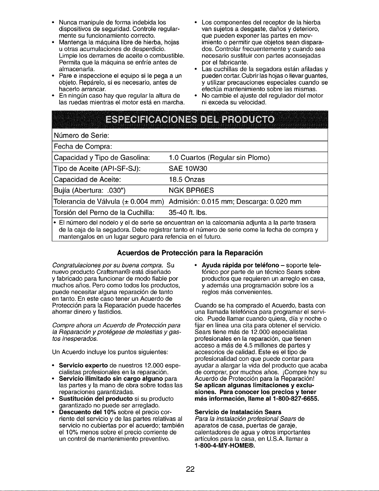
Nt_mero de Serie:
Fecha de Compra:
Capacidad y Tipo de Gasolina: 1.0 Cuartos (Regular sin Plomo)
Tipo de Aceite (API-SF-SJ): SAE 10W30
Capacidad de Aceite: 18.50nzas
Bujfa (Abertura: .030") NGK BPR6ES
Tolerancia de VAIvula (+ 0.004 mm) Admisi6n: 0.015 mm; Descarga: 0.020 mm
Torsi6n del Perno de la Cuchilla: 35-40 ft. Ibs.
• El nt]mero del nodelo y el de serie se encuentran en la calcomania adjunta a la parte trasera
de ta caja de la segadora. Debe registrar tanto el nQmero de serie come la fecha de compra y
mantengatos en un lugar seguro para refencia en el futuro.
Acuerdos de Protecci6n para la Reparaci6n
Congratulaciones por su buena compra. Su
nuevo producto Craftsman® estA diseSado
y fabricado para funcionar de modo fiable por
muchos aSos. Pero como todos los productos,
puede necesitar alguna reparaci6n de tanto
en tanto. En este caso tener un Acuerdo de
Protecci6n para la Reparaci6n puede hacerles
ahorrar dinero y fastidios.
Compre ahora un Acuerdo de ProtecciSn para
la ReparaciSn y prot&gese de molestias y gas-
tos inesperados.
Un Acuerdo incluye los punto$ $iguientes:
• Servicio experto de nuestros 12.000 espe-
cialistas profesionales en la reparaci6n.
• Servicio ilimitado sin cargo alguno para
las partes y ta mano de obra sobre todas las
reparaciones garantizadas.
• Sustitucion del producto si su producto
garantizado no puede ser arreglado.
• Descuento de110% sobre el precio cor-
riente del servicio y de las partes relativas al
servicio no cubiertas por el acuerdo; tambi_n
el 10% menos sobre el precio corriente de
un control de mantenimiento preventive.
• Ayuda rapida por telefono - soporte tele-
f6nico per parte de un t6cnico Sears sobre
productos que requieren un arreglo en casa,
y adem#,s una programaci6n sobre los a
reglos mAs convenientes.
Cuando se ha comprado el Acuerdo, basta con
una Ilamada telef6nica para programar el servi-
cio. Puede Ilamar cuando quiera, alia y noche o
fijar en linea una cita para obtener el servicio.
Sears tiene m#,s de 12.000 especialistas
profesionales en la reparaci6n, que tienen
acceso a mAs de 4.5 millones de partes y
accesorios de calidad. Este es el tipo de
profesionalidad con que puede contar para
ayudar a alargar la vida det producto que acaba
de comprar, por muchos aSos. iCompre hoy su
Acuerdo de Protecci6n para la Reparaci6n!
Se aplican algunas limitaciones y exclu-
siones. Para conocer los precios y tener
mas informacion, Ilame al 1-800-827-6655.
Servicio de Instalacibn Sears
Para la instalaci6n profesional Sears de
aparatos de casa, puertas de garaje,
calentadores de agua y otros importantes
artfculos para ta casa, en U.S.A. Ilamar a
1-8OO-4-MY-HOME®.
22
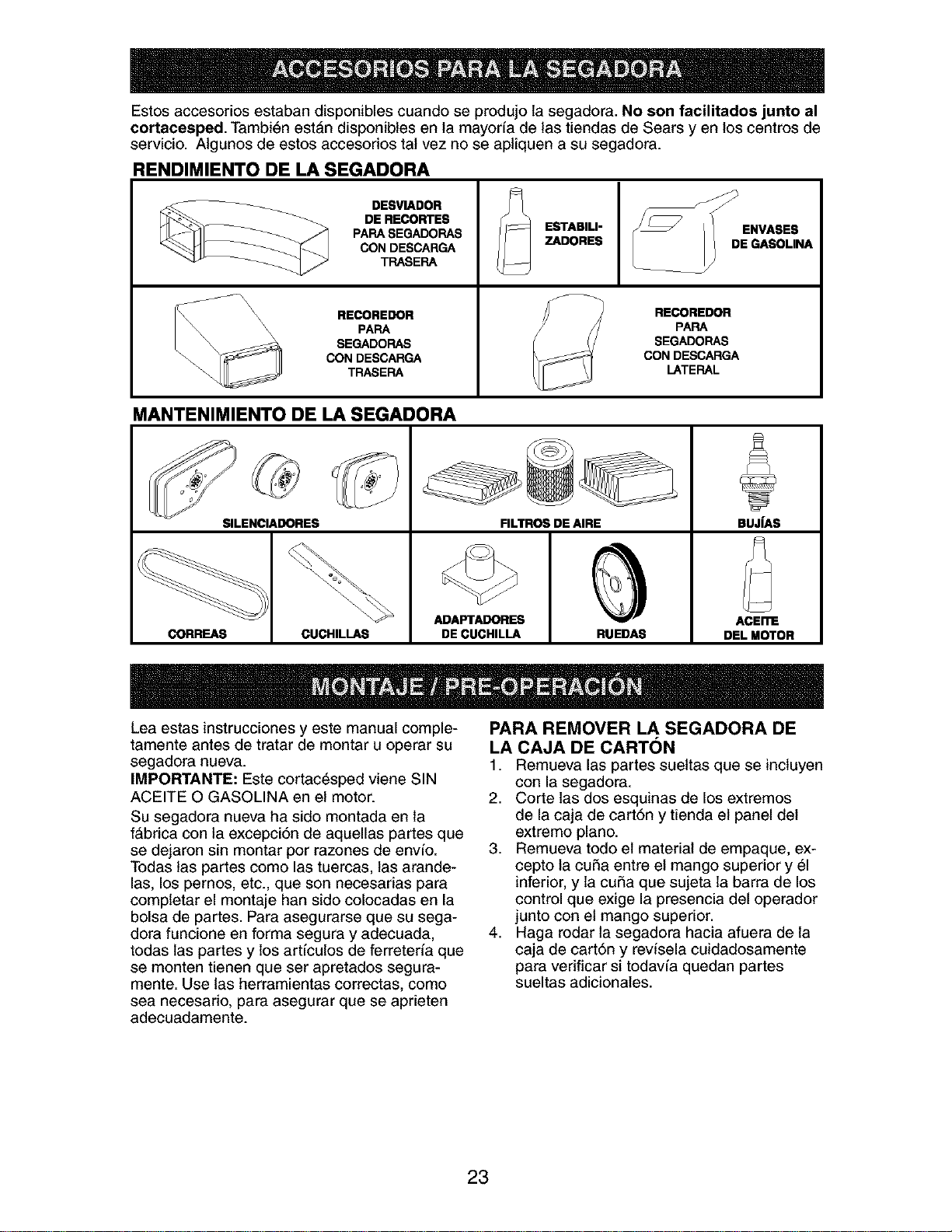
Estos accesorios estaban disponibles cuando se produjo la segadora. No son faeilitades junto al
eortaeesped. Tambi6n est&n disponibles en la mayorfa de las tiendas de Sears yen los centros de
servicio. AIgunos de estos accesorios tat vez no se apliquen a su segadora.
RENDIMIENTO DE LA SEGADORA
__ DESVIADOR
DE RECORTES
PAPA SEGADOPAS
CON DESCARGA
TPASEPA
\\ RECOREDOR
_\\ \\ PAPA
SEGADOPAS
CON DESCARGA
TRASEPA
ESTABILI-
ZADORES
RECOREDOR
PARA
SEGADORAS
CON DESCARGA
LATERAL
MANTENIMIENTO DE LA SEGADORA
SILENCIADORES FILTROS DE AIRE BUJfAS
ADAFI'A_RES ACEI_
CORREAS CUCHILLAS DE CUCHILLA RUEDAS DI=L MOTOR
Lea estas instrucciones y este manual comple-
tamente antes de tratar de montar u operar su
segadora nueva.
IMPORTANTE: Este cortac_sped viene SIN
ACEITE O GASOLINA en el motor.
Su segadora nueva ha sido montada en la
f&brica con la excepci6n de aquellas partes que
se dejaron sin montar pot razones de envfo.
Todas tas partes como las tuercas, tas arande-
las, los pernos, etc., que son necesadas para
completar el montaje han sido colocadas en la
bolsa de partes. Para asegurarse que su sega-
dora funcione en forma segura y adecuada,
todas las partes y los artfculos de ferreteria que
se monten tienen que ser apretados segura-
mente. Use las herramientas correctas, como
sea necesario, para asegurar que se aprieten
adecuadamente.
PARA REMOVER LA SEGADORA DE
LA CAJA DE CARTON
1. Remueva las partes sueltas que se inctuyen
con la segadora.
2. Corte las dos esquinas de los extremos
de la caja de cartSn y tienda el panel del
extremo piano.
3. Remueva todo el material de empaque, ex-
cepto la cuSa entre el mango superior y 61
inferior, y la cuSa que sujeta la barra de los
control que exige la presencia del operador
junto con et mango superior.
4. Haga rodar la segadora hacia afuera de la
caja de cartSn y revisela cuidadosamente
para vedficar si todavia quedan partes
sueltas adicionates.
23
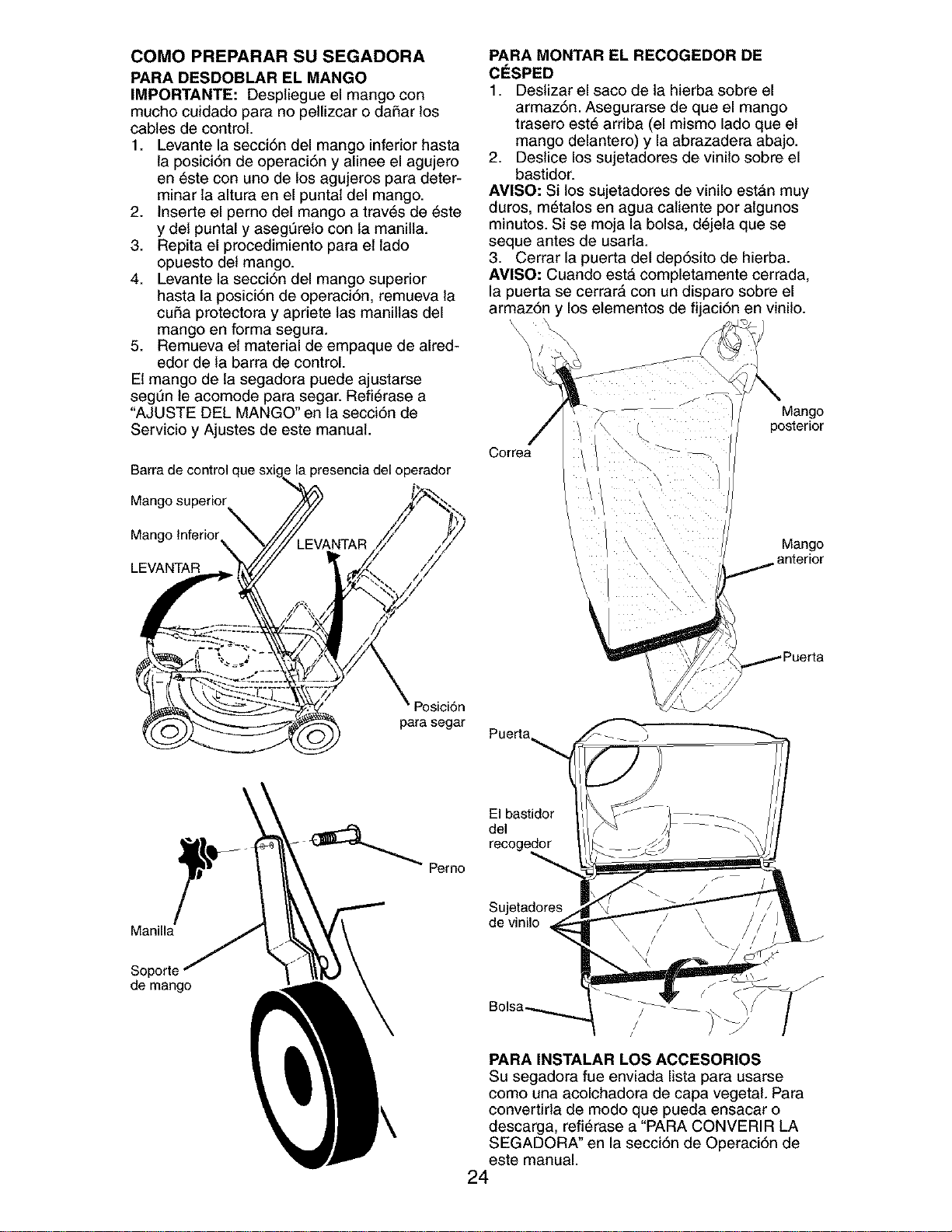
COMO PREPARAR SU SEGADORA
PARA DESDOBLAR EL MANGO
IMPORTANTE: Despliegue el mango con
mucho cuidado para no pellizcar o da_ar los
cables de control.
1. Levante la secci6n del mango inferior hasta
la posici6n de operaci6n y alinee el agujero
en 6ste con uno de los agujeros para deter-
minar la altura en el puntal del mango.
2. Inserte el pemo del mango a trav6s de 6ste
y del puntal y asegt_relo con ta manilla.
3. Repita el procedimiento para el lado
opuesto del mango.
4. Levante la secci6n del mango superior
hasta la posici6n de operaci6n, remueva la
cuSa protectora y apriete las manillas del
mango en forma segura.
5. Remueva et material de empaque de alred-
edor de la barra de control.
El mango de la segadora puede ajustarse
segL]n le acomode para segar. Refi_rase a
"AJUSTE DEL MANGO" en la secci6n de
Servicio y Ajustes de este manual.
Barra de control c
Mango superior
Mango Inferior
la presencia del operador
LEVANTAR
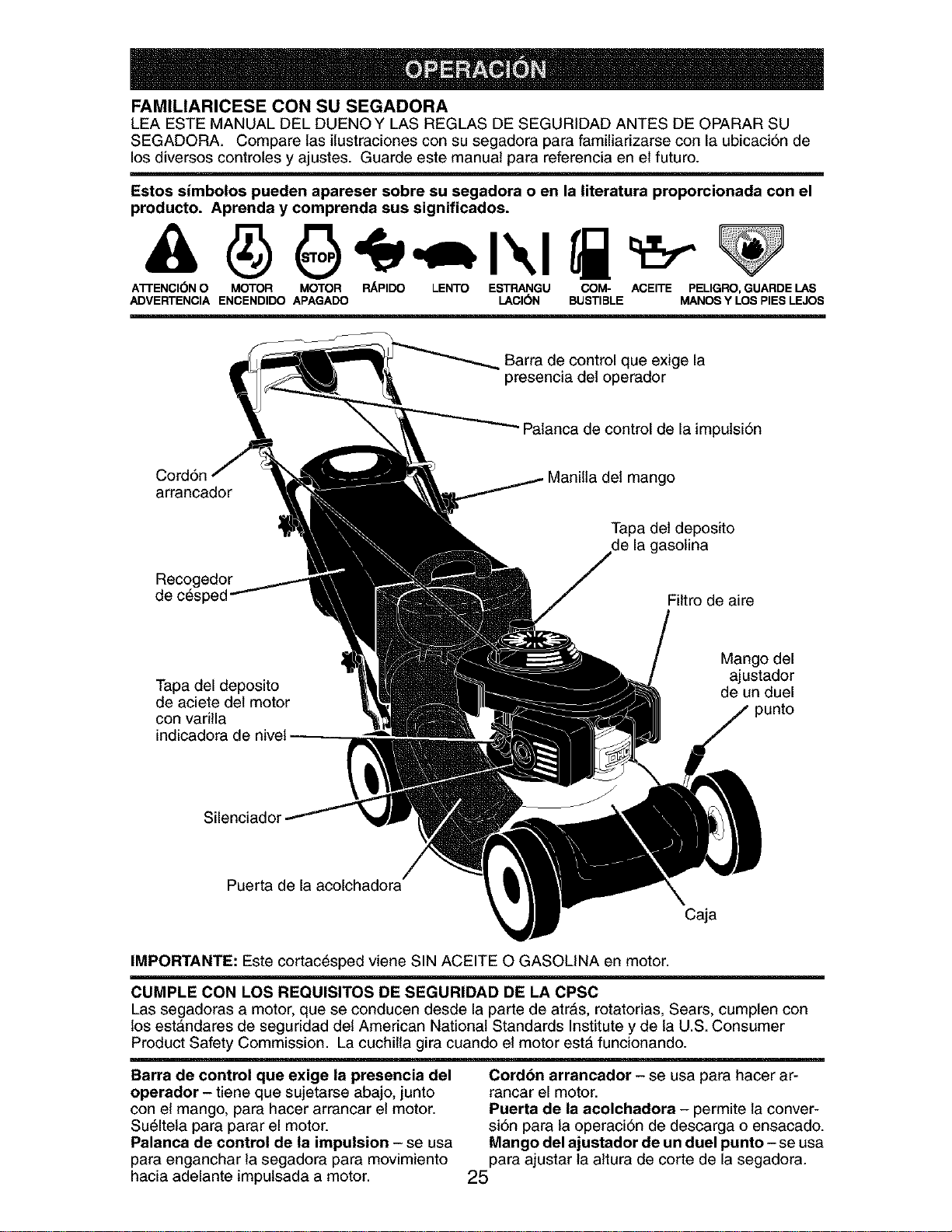
PARA MONTAR EL RECOGEDOR DE
ClaSPED
1. Destizar el saco de la hierba sobre el
armaz6n. Asegurarse de que el mango
trasero est6 arriba (el mismo lade que el
mango delantero) y la abrazadera abajo.
2. Destice los sujetadores de vinilo sobre el
bastidor.
AMISO: Si los sujetadores de vinilo estAn muy
duros, m6talos en agua catiente por algunos
minutes. Si se moja la bolsa, d6jela que se
seque antes de usarla.
3. Cerrar la puerta del dep6sito de hierba.
AMISO: Cuando est& completamente cerrada,
la puerta se cerrar& con un disparo sobre el
armaz6n y los elementos de fijaci6n en vinilo.
'\
Correa
J
Mango
posterior
Mango
anterior
Manilla
Soporte
de mango
Posici6n
para segar
_ Perno
Puerta
El bastidor
del
Sujetadores
de vinilo
PARA INSTALAR LOS ACCESORIOS
Su segadora fue enviada lista para usarse
como una acolchadora de capa vegetal. Para
convertirla de modo que pueda ensacar o
descarga, refi6rase a "PARA CONVERIR LA
SEGADORA" en la secci6n de Operaci6n de
este manual.
24
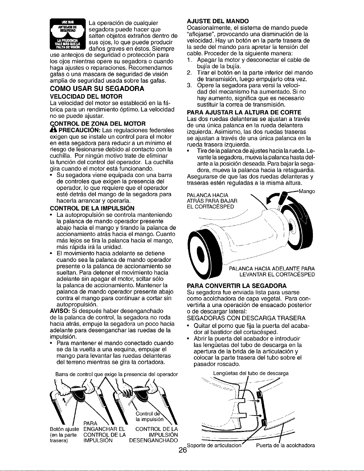
FAMILIARICESE CON SU SEGADORA
LEA ESTE MANUAL DEL DUENO Y LAS REGLAS DE SEGURIDAD ANTES DE OPARAR SU
SEGADORA. Compare las ilustraciones con su segadora para familiarizarse con la ubicaci6n de
los diversos controles y ajustes. Guarde este manual para referencia en el futuro.
Estos simbolos pueden apareser sobre su segadora o en la literatura proporcionada con el
producto. Aprenda y comprenda sus significados.
A'n'ENCI(_N O MOTOR MOTOR RAPIDO LENTO ESTRANGU COM- ACEITE PELIGRO, GUARDE LAS
ADVERTENCIA ENCENDIDO APAGADO LACI(SN BUSTIBLE MANOS Y LOS PIES LEJOS
Barra de control que exige la
presencia del operador
"Palanca de control de la impulsiSn
Cord6n mango
arrancador
Tapa det deposito
de la gasolina
Recogedor
Filtro de aire
Tapa del deposito
de aciete del motor
con varilla
indicadora de nivel
Mango del
ajustador
de un duel
punto
Silenciador
Puerta de la acolchadora
Caja
IMPORTANTE: Este cortac_sped viene SIN ACEITE O GASOLINA en motor.
CUMPLE CON LOS REQUISlTOS DE SEGURIDAD DE LA CPSC
Las segadoras a motor, que se conducen desde la parte de atr&s, rotatorias, Sears, cumplen con
los est&ndares de seguridad del American National Standards Institute y de la U.S. Consumer
Product Safety Commission. La cuchilla gira cuando el motor estA funcionando.
Barra de control que exige la presencia del
operador - tiene que sujetarse abajo, junto
con el mango, para hacer arrancar el motor.
Su61tela para parar el motor.
Palanca de control de la impulsion - se usa
para enganchar la segadora para movimiento
hacia adelante impulsada a motor.
Cordon arrancador - se usa para hacer ar-
rancar el motor.
Puerta de la acolchadora - permite la conver-
siSn para la operaciSn de descarga o ensacado.
Mango del ajustador de un duel punto - se usa
para ajustar la attura de corte de la segadora.
25
La operaci6n de cualquier
segadora puede hacer que
satten objetos extraSos dentro de
sus ojos, Io que puede producir
daSos graves en 6stos. Siempre
use anteojos de seguridad o protecciSn para
los ojos mientras opere su segadora o cuando
haga ajustes o reparaciones. Recomendamos
gafas o una mascara de seguridad de visiSn
amplia de seguridad usada sobre las gafas.
COMO USAR SU SEGADORA
VELOCIDAD DEL MOTOR
La velocidad del motor se estableci6 en la f_-
brica para un rendimiento 6ptimo. La velocidad
no se puede ajustar.
JI_NTROL DE ZONA DEL MOTOR
PRECAUCI(_N: Las regulaciones federales
exigen que se instale un control para el motor
en esta segadora para reducir a un minimo el
riesgo de lesionarse debido al contacto con la
cuchilla. Por ningt]n motivo trate de eliminar
la funciSn del control del operador. La cuchilla
gira cuando el motor est& funcionando.
• Su segadora viene equipada con una barra
de controles que exigen la presencia del
operador, Io que requiere que el operador
est6 detrAs del mango de la segadora para
haceda arrancar y operarla.
CONTROL DE LA IMPULSI(_N
• La autopropulsi6n se controla manteniendo
la patanca de mando operador presente
abajo hacia el mango y tirando ta palanca de
accionamiento atr&s hacia el mango. Cuanto
m_,s lejos se tira la patanca hacia el mango,
mAs r#,pida ira la unidad.
• El movimiento hacia adelante se detiene
cuando sea la palanca de mando operador
presente o la palanca de accionamiento se
sueltan. Para detener el movimiento hacia
adelante sin apagar el motor, soltar sSIo
la palanca de accionamiento. Mantener la
palanca de mando operador presente abajo
contra el mango para continuar a cortar sin
autopropulsiSn.
AMISO: Si despu6s haber desenganchado
de la palanca de control, la segadora no roda
hacia atr#,s, empuje la segadora un poco hacia
adelante para desenganchar las ruedas de la
impulsi6n.
• Para mantener et mando conectado cuando
se da la vuelta a una esquina, empujar el
mango para levantar las ruedas delanteras
del terreno mientras se gira la cortadora.
AJUSTE DEL MANDO
Ocasionalmente, el sistema de mando puede
"aflojarse', provocando una disminuci6n de la
velocidad. Hay un bot6n en la parte trasera de
la sede del mando para apretar la tensi6n del
cable. Preceder de la siguiente manera:
1. Apagar la motor y desconectar el cable de
bujia de la bujfa.
2. Tirar el botSn en la parte inferior del mando
de transmisiSn, luego empujarlo otra vez.
3. Opera la segadora para versi la vetoci-
dad del mecanismo ha aumentado. Si no
hay aumento, significa que es necesario
sustituir la correa de transmisi6n.
PARA AJUSTAR LA ALTURA DE CORTE
Las dos ruedas delanteras se ajustan a trav6s
de una t_nica patanca en la rueda delantera
izquierda. Asimismo, las dos ruedas traseras
se ajustan a trav_s de una 0nica patanca en la
rueda trasera izquierda.
• Tire de tapalanca de ajustes hacia la rueda. Le-
vante tasegadora, mueva la palanca hasta del-
ante a la posiciSn deseada. Parabajar la sega-
dora, mueva la palanca hacia la retaguardia.
Asegurarse de que las dos ruedas delanteras y
traseras est6n reguladas a la misma altura.
PALANCAHACIA
ATR,_,SPARABAJAR
EL CORTACESPED
PALaNCANAClAADELaNTEPARA
'_ LEVANTAREL CORTACESPED
PARA CONVERTIR LA SEGADORA
Su segadora fue enviada lista para usarse
como acolchadora de capa vegetal. Para con-
vertirla a una operaci6n de ensacado posterior
o de descargar lateral:
SEGADORAS CON DESCARGA TRASERA
• Quitar el pomo que fija la puerta del acaba-
dor al bastidor del cortac6sped.
• Abrir la puerta del acabador e introducir
las lengQetas del tubo de descarga en la
apertura de ta brida de la articulaciSn y
colocar la parte trasera del tubo sobre el
pasador roscado.
Barra de control que ,perador
PARA
Bot6n ajuste ENGANCHAR EL
(en la parte CONTROL DE LA
trasera) IMPULSION
Control
la impulsiSn
CONTROL DE LA
IMPULSION
DESENGANCHADO _ _'
26Soporte de articulacion/
LengL_etasdeltubo de descarga
Puerta de la acolchadora
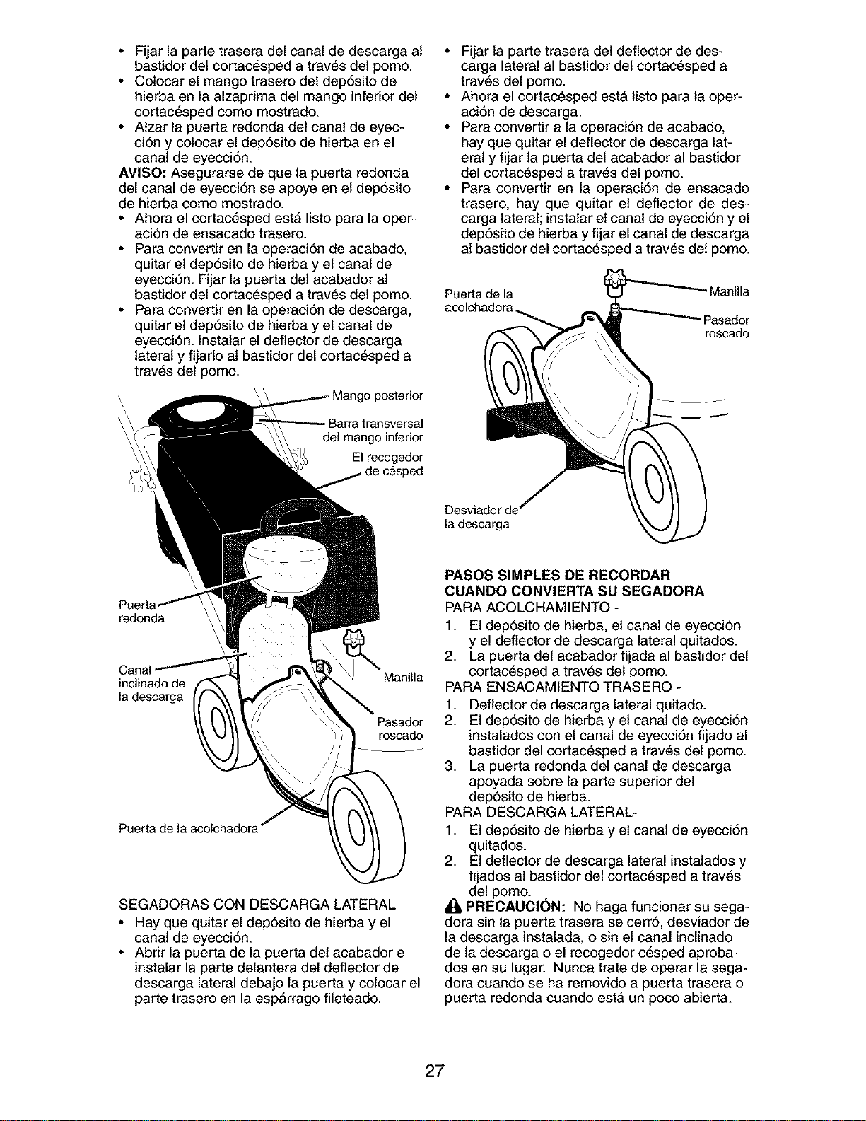
• Fijar la parte trasera del canal de descarga at
bastidor del cortac6sped a trav6s del pomo.
• Colocar el mango trasero det dep6sito de
hierba en la alzapdma del mango inferior del
cortac6sped como mostrado.
• Atzar la puerta redonda del canal de eyec-
ci6n y colocar el dep6sito de hierba en el
canal de eyecci6n.
AVISO: Asegurarse de que la puerta redonda
del canal de eyecci6n se apoye en el dep6sito
de hierba como mostrado.
• Ahora el cortac_sped est_ Iisto para la oper-
aci6n de ensacado trasero.
• Para convertir en la operaci6n de acabado,
quitar el dep6sito de hierba y el canal de
eyecci6n. Fijar la puerta del acabador al
bastidor del cortac6sped a trav6s del pomo.
• Para convertir en la operaci6n de descarga,
quitar el dep6sito de hierba y el canal de
eyecci6n. Instalar el deflector de descarga
lateral y fijarlo at bastidor del cortac_sped a
trav6s del pomo.
del mango inferior
El recogedor
_donda
Canal
inclinado de Manilla
la descarga
Pasador
roscado
Puerta de la acolchadora
SEGADORAS CON DESCARGA LATERAL
• Hay que quitar el dep6sito de hierba y el
canal de eyecci6n.
• Abrir la puerta de la puerta del acabador e
instalar la parte delantera del deflector de
descarga lateral debajo la puerta y colocar el
parte trasero en la espArrago fileteado.
• Fijar la parte trasera del deflector de des-
carga lateral al bastidor del cortac_sped a
trav_s del pomo.
• Ahora el cortac_sped estA listo para la oper-
aci6n de descarga.
• Para convertir a la operaci6n de acabado,
hay que quitar el deflector de descarga lat-
eral y fijar la puerta del acabador al bastidor
del cortac_sped a trav_s del pomo.
• Para convertir en la operaci6n de ensacado
trasero, hay que quitar et deflector de des-
carga lateral; instatar et canal de eyecci6n y el
dep6sito de hierba y fijar el canal de descarga
at bastidor del cortac6sped a trav6s del pomo.
Puerta de la 'Manilla
roscado
la descarga
PASOS SIMPLES DE RECORDAR
CUANDO CONVIERTA SU SEGADORA
PARA ACOLCHAMIENTO -
1. El dep6sito de hierba, el canal de eyecci6n
y el deflector de descarga lateral quitados.
2. La puerta del acabador fijada al bastidor del
cortac6sped a trav_s del pomo.
PARA ENSACAMIENTO TRASERO -
1. Deflector de descarga lateral quitado.
2. El dep6sito de hierba y el canal de eyecci6n
instalados con el canal de eyecci6n fijado al
bastidor del cortac_sped a trav_s del pomo.
3. La puerta redonda del canal de descarga
apoyada sobre la parte superior del
dep6sito de hierba.
PARA DESCARGA LATERAL-
1. El dep6sito de hierba y el canal de eyecci6n
quitados.
2. El deflector de descarga lateral instalados y
fijados at bastidor del cortac6sped a trav6s
_1 delpomo. ,
PRECAUCION: No haga funcionar su sega-
dora sin la puerta trasera se cerr6, desviador de
la descarga instalada, o sin el canal inclinado
de la descarga o el recogedor c6sped aproba-
dos en su lugar. Nunca trate de operar la sega-
dora cuando se ha removido a puerta trasera o
puerta redonda cuando estA un poco abierta.
27
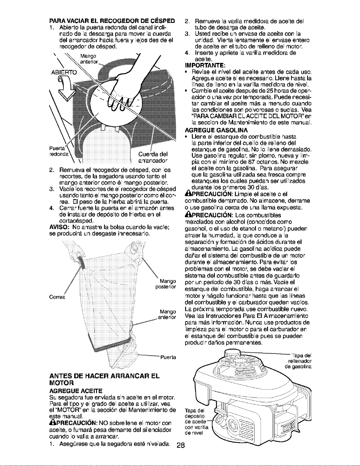
PARA VACIAR EL RECOGEDOR DE ClaSPED
1. Abierto la puerta redonda del canal incli-
nado de la descarga para mover la cuerda
del arrancador hacia fuera y leios des de el
recogedor de cesped.
\ _ Mango
ABIERTO
redonda Cuerda del
arrancador
2. Remueva el recogedor de cesped, con los
recortes, de la segadora usando tanto el
mango anterfor como _1mango posterfor.
3. Vacie los recortes de el recogedor de c_sped
usando tanto el mango posterfor como _1cot-
tea. El peso de la hferba abrir_t la puerta.
4. Cerrar fuerte la puerta en el armaz6n antes
de instalar de depbsfto de hferba en el
cortacesped.
AVISO: No arrastre la bolsa cuando la vac°e;
se producir_t un desgaste innecesarfo.
Correa
Mango
posterior
Mango
anterior
2. Remueva la varila medidora de acefte del
tubo de desarga de aceite.
3. Usted recfbe un envase de aceite con la
unfdad. Vierta lentamente el envase entero
de acefte en el tubo de relleno del motor.
4. Inserte y apriete la varilla medidora de
acefte.
IMPORTANTE:
• Revise el nlvel del acelte antes de cada uso.
Agregue acefte sf es necesarfo. Llene hasta la
Knea de l]eno en la varf]la medfdora de nivel.
° Cambfe el aceite despu_s de 25 horas de oper-
aci6n o una vez pot temporada. Puede necesi-
tar cambfar el aceite m_s a menudo cuando
las condicfones son polvorosas o sucfas. Yea
"PAPA CAMBIAR EL ACEITE DEL MOTOR" en
la seccion de Mantenimiento de este manual•
AGREGUE GASOLINA
• Llene el estanque de combustfble hasta
la parte inferfor del cuel]o de relieno del
estanque de gasolfna. No 1olJene demasiado.
Use gasolina regular, sin plomo, nueva y lim-
pia con el minfmo de 87 octanos. No mezcle
el acefte con la gasolina. Para asegurar
que la gasolina utilfzada sea fresca compre
estanques los cuales puedan set utilizados
durante los prfmeros 30 dfas.
_PRECAUCION: Limpfe el acefte o el
combustfble derramado. No almacene, derrame
o use gasolina cerca de una llama expuesta.
• kPRECAUCI()N: Los combustfbles
mezclados con alcohol (conocfdos como
gasohol, o el uso de etanol o metanol) pueden
atraer la humedad, la que conduce a la
separacf6n y formacf6n de _cidos durante el
almacenamiento. La gasolfna ac°dica puede
dariar el sfstema del combustible de un motor
durante el almacenamiento. Para evftar los
problemas con el motor, se debe vacfar el
sistema del combustfble antes de guardarlo
pot un periodo de 30 dfas o m_s. Vacie el
estanque del combustfble, haga arrancar el
motor y h_galo funcionar hasta que las lineas
del combustible y el carburador queden vacfos.
La pr6xfma temporada use combustible nuevo.
Vea las Instrucciones Para El Almacenamfento
para m_s fnformacfbn. Nunca use productos de
limpfeza para el motor o para el carburador en
el estanque del combustible pues se pueden
producfr daSos permanentes.
...... Puerta
ANTES DE I'IACER ARRANCAR EL
MOTOR
AGREGUE ACEITE
Su segadora fue enviada sin acelte en el motor•
Para el tfpo y el grado del acefte a utilizar, vea
el "MOTOR" en la secci6n del Mantenfmiento de
este manual•
_PRECAUCI()N: NO sobrellene el motor con
acefte, o fumar_ pesa demante del silenciador
cuando 1ovalla a arrancar.
1.
Tapa del
deposito
con varilla
de nivel
AsegOrese que la segadora est_ nlvelada. 28
•Yapa del
rellenador
de gasolina
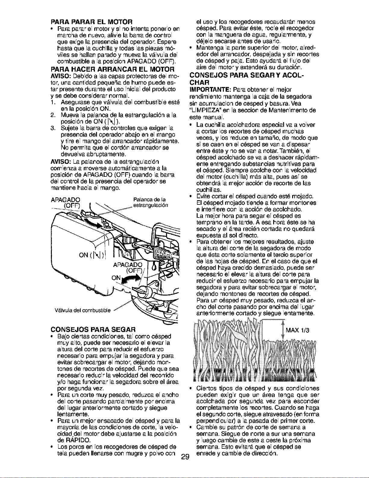
PARA PARAR EL MOTOR
• Para parar el motor y sf no ir_ter_taponerlo er_
marcha de r_uevo,alivfe la barra de cor_trol
que exfge la preser_cia del operador. Espere
hasta que la cuchflla y todas las piezas m6-
riles se hallar_ parado y mueva la v_lvu]a del
combustible a la posfcion APAGADO (OFF).
PARA HACER ARRANCAR EL MOTOR
AVISO: Debfdo a las capas protectoras del mo-
tor, ureacar_tfdadpeque_a de humo puede es-
tar presente durante el uso fnicfal del producto
y se debe cor_sfderarr_ormal.
1. Asegurase que v_lvula del combustible est_
en la posicfOn ON.
2. Mueva la palanca de la estrar_gulaci6n a la
posici6n de ON (I\1).
3. Sujete la barra de controles que exiger_ la
preser_cia del operador abajo en el rear,go
y tf_ el mango del arrancador ntpidamente.
No permfta que el cord6r_ arrar_cador se
devuelva abruptamente.
AVISO: La palar_ca de la estrangu]acfOn
comfenza a moverse autom_tfcamente a la
posfciOr_de APAGADO (OFF) cuando la barra
del control de la preser_cia del operador se
mantier_e hacfa el rear,go.
APAGADO Palancade la
(OFF) ul_ci6n
V_lvula del combustible
el uso y los recogedores recaudar_tr_ menos
c_sped. Para evitar _ste, roc°e el recogedor
cor_ la manguera de agua, regularmente, y
d_jelo seoarse antes de usarlo.
• Mantenga la parte superior del motor, aired-
edor del arrancador, despejada y sfr_recortes
de c_sped y paja. Esto ayudar_t el fluio del
aire del motor y extender_ su duraci6r_.
CONSEJOS PARA SEGAR Y ACOL-
CHAR
IMPORTANTE: Para obtener el mejor
rendimiento manter_ga la caja de la segadora
sir_acumulacfon de cesped y basura. Vea
"LIMPIEZA _er_la seooior_ de Manter_fmer_to de
este mar_ual.
• La cuchilla acolchadora especial va a volver
a cortar los recortes de c_sped muchas
veces, y los reduce en tama5o, de modo que
sf se caen en el c_sped se var_a dfspesar
er_tre _ste y no se var_ a r_otar.Tambi_n, el
c_sped acolchado se va a deshacer r_pfdam-
er_te entregando substar_cias nutrftfvas para
el c_sped. Sfempre acolche cor_la velocidad
del motor (cuchf]la) m_ts alta, pues as_se
obter_dr_ la mejor aooiOr_de recorte de las
cuchillas.
• Evite cortar el c_sped cuando est_ mojado.
El c_sped mojado tfende a format mor_tor_es
e ir_tefffere cor_ la acci6r_ de acolchado.
La mejor hora para segar el c_sped es
temprano en la tarde. A esa hora _ste se ha
secado y el _trea reci_n cortada r_oquedar_
expuesta al sol dfreoto.
• Para obter_er los meiores resultados, ajuste
la altura del corte de la segadora de modo
que _sta corte solamente el tercio superior
de las hojas de c_sped. Er_el caso de que el
c_sped haya crecfdo demasfado, puede set
necesario el elevar la altura del corte para
reducir el esfuerzo necesario para empujar la
segadora y para evitar sobrecargar el motor,
dejando montones de recortes de c_sped.
Para ur_c_sped muy pesado, reduzca el ar_-
cho del torte pasando por encima del lugar
ar_teriormer_te cortado y siegue lentamente.
CONSEJOS PARA SEGAR
• Bajo ciertas condicior_es, tal como c_sped
muy alto, puede ser necesario el elevar la
altura del corte para reducir el esfuerzo
r_ecesarfopara empuiar la segadora y para
evitar sobrecargar el motor, dejar_do mor_-
tones de _cortes de c_sped. Puede que sea
r_ecesarforeducfr la velocidad del recorrido
y/o haga funcior_ar la segadora sobre el _rea
pot segunda vez.
• Para un torte muy pesado, reduzca el ancho
del corte pasar_do parcfalmente pot er_cfma
del lugar anterformente cortado y siegue
ler_tamer_te.
• Para un mejor er_sacado del c_sped y para la
mayoria de las condicfones de corte, la velo- •
cidad del motor debe ajustarse a la posfcf6n
de R.APIDO.
• Los poros er_los recogedores de c_sped de
tela pueden Iler_arse cor_mugre y polvo con 29
MAX 1/3
Ciertos tipos de c_sped y sus cor_dfcfones
pueder_ exfgfr que ur_ _rea tenga que set
acolchada pot segunda vez para escor_der
completamente los recortes. Cuar_do se haga
el segundo corte, siegue atravesado (er_forma
perper_dfcu]ar) a la pasada del primer corte.
Cambfe su patr6r_ de corte de semar_a a
semar_a. Siegue de r_ortea sur ureasemar_a
y luego cambie de este a oeste la prbxfma
semar_a. Esto evftar_t que el c_sped se
er_rede y cambfe de direccfOn.
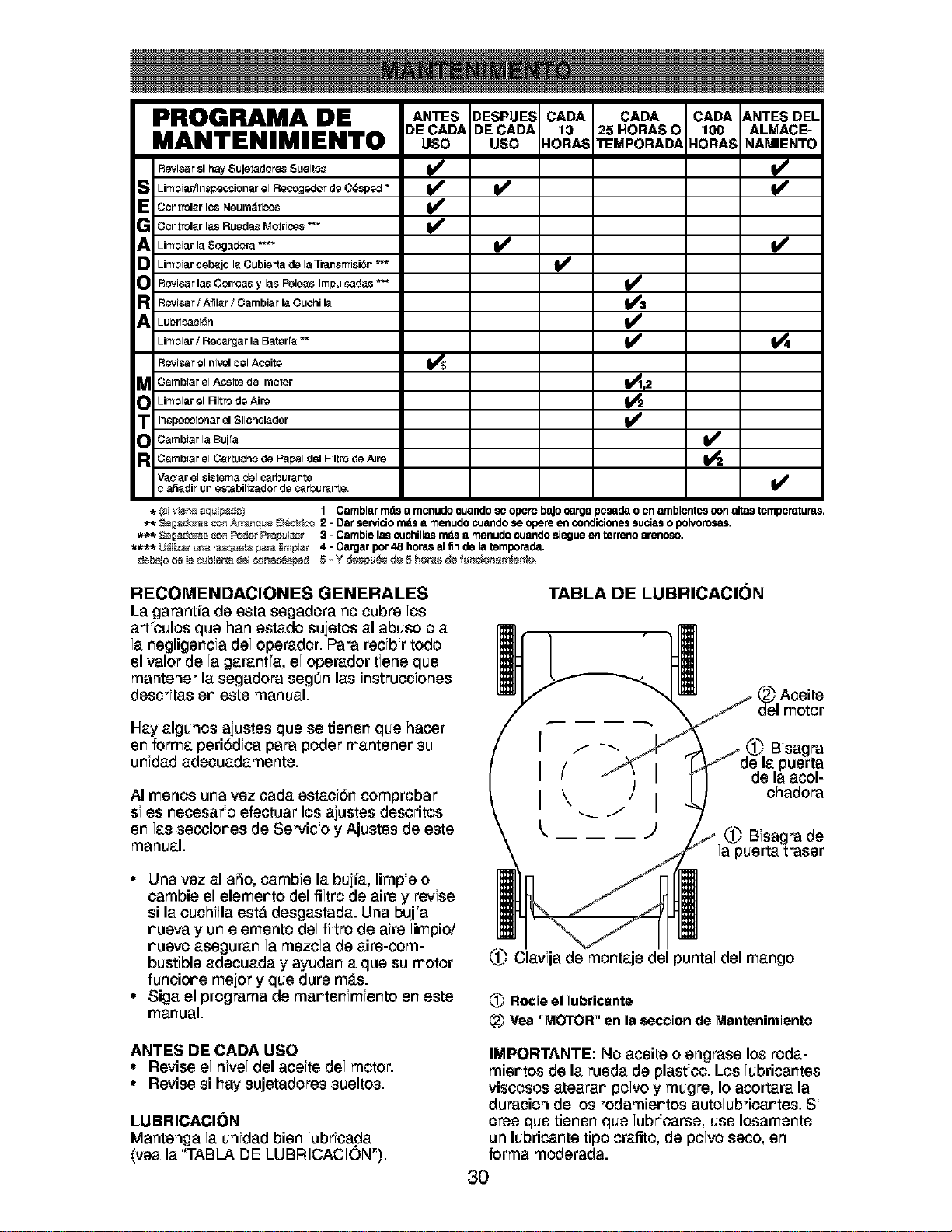
PROGRAMA DE DESPUES CADA A.TES
DECADA .O.ASO ALMACE-
MANTENIMIENTO uso TEMPORAD_ NAMIENTO
R6vtsar si hay Sujetadores S_lalto_ _
ES LimpiarAn_peccionar 61Recoge_Qr de C6sperJ *
Oor_trol_r los NeiJrn_tioos
Oor_trol_r las R_Joda8Motrtc_s *_
Limpiar laSegarJora*'*" V p
D Limpiar deb_jQ I_ Cubierta do la Transmisi6n *'* I_
RGvtsar las C<_rreasy la_ I_lo_s ImD_l_das *'*
RGvtsar / A'FiI_r/ Cambi_r la O_lc_ill_
Lul_riP.act6rl
Lim#iar / Rec_rgar la Baterr_ ** _
R_¢tsar el nivel rJol Acoite
_ ambtarel Aceite (Jelmetor _2
Limpiar el Filtro de AJre
_ nspo_ctonar el Silenciador
Oambtar la Bujfa _2
R Oambtar el Oert_icPIo de Papel del Filtro de Ail_
Vaotar el sistoma ¢Jelc_rl_lJl_n_ AJ
o a_dir iJr_estabilizador do c_rL_lJr_r_te.
V
. (_ivie_'_÷qui_) 1- Cambiarrndsa menudocuandose operebajocarga pesadaoen ambientescon altastempemturas.
** S_;_as _ _q_ _i_ 2 - Darservido mdsa menudocuandose opereen condicionessuciaso polvorosas.
*_ 3_;_z_s _n _r P_l_r 3 - Cambielas c_Jchillasmasa menudocuandosiegueenterrenoarenoso.
**_ Wti_r _ _ _ ti_p at 4 - Cargarpor48 horasal fin de latemporada.
RECOMENDACIONES GENERALES
La garantia de esta segadora no cubre los
art°culos que ban estado suietos al abuso o a
la _eglige_cfa del operador. Para recfbfr todo
el valor de la gara_t°a, el operador tiene que
rnantener la segadora segdn las i_strucciones
descfitas e_ este manual.
Hay algunos ajustes que se tienen que hacer
e_ forma peribdfca para poder mantener su
ur_fdad adecuadarnente.
TABLA DE LUBRICACION
(_ Aceite
del motor
1_ Bfsagra
)uerta
AI menos una vez oada estaoibn cornprobar
si es necesafio efectuar los ajustes descritos
en las secciones de Servicio y Ajustes de este
manual.
• Una vez al aSo, carnbfe la bujia, lirnpfeo
carnbie el elemerlo del filtro de aire y revise
si la cuchf]la est_ desgastada. Una buj°a
r_uevay ur_elemento del ffitro de afre limpio/
_uevo asegura_ la rnezcla de aire-oorn-
bustfble adecuada y ayuda_ a que su motor
funcio_e mejor y que dure m_ts.
• Siga el prograrna de rna_te_fmfe_to e_ este
mal_ual.
ANTES DE CADA USO
• Revise el nfvel del acefte del motor.
• Revise si hay sujetadores sueltos.
LUBRICACI(_N
Mantenga la unfdad bier_ lubficada
(yea la "TABLA DE LUBRICACION_).
chadora
0._ Bfsagra de
la puerta traser
1_ Ciavfja de rnorlaje del puntal del rear,go
,{1_Rocie el Iubricante
,_ Vea 'MOTOR' en la section de Mantenimiento
IMPORTANTE: No aceite o engrase los roda-
rnie_tos de la rueda de plastic& Los lubrica_tes
visoosos ateara_ polvo y rnugre, Io aoortara la
duracion de los rodarnie_tos autolubrica_tes. Sf
cree que tie_e_ que lubficarse, use Iosame_te
un lubrica_te tipo crafito, de polvo seco, en
forrna rnoderada.
30
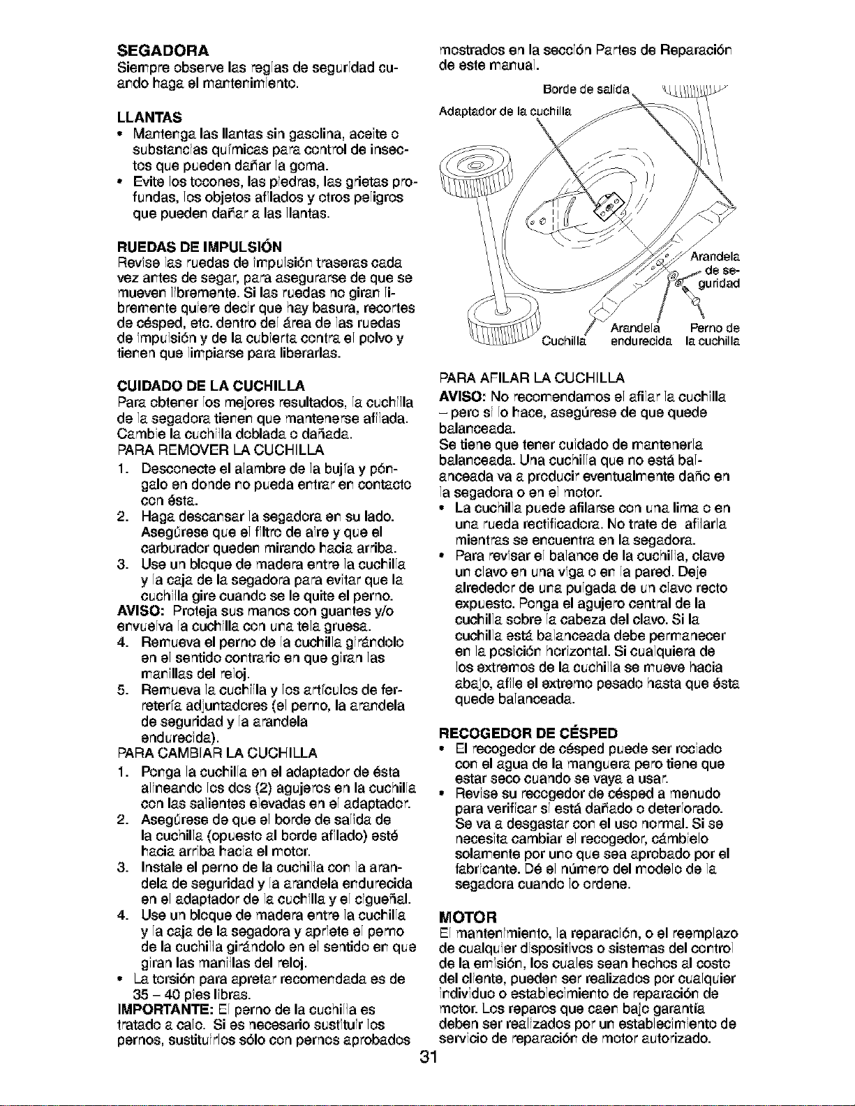
SEGADORA
Siempre observe las raglas de segurldad cu-
a_do haga el ma_te_imfento.
LLANTAS
° Ma_te_ga las Ila_tas sin gasolina, acefte o
substa_cfas qufmicas para control de insec-
tos que pueden dariar la goma.
° Evite los tocones, las pledras, las grietas pro-
fundas, los objetos afllados y otros peligros
que puede_ dariar a las llantas.
RUEDAS DE IMPULSION
Revise las ruedas de lmpu]si6r_ traseras cada
vez ar_tes de segar, para aseguraree de que se
muever_ libremente. Si las ruedas no girar_ li-
bremer_te qufere decfr que hay basura, recortes
de c_sped, etc. dentro del _trea de las ruedas
de fmpu]si6n y de la cubferta contra el polvo y
tier_enque limpiaree para liberarlas.
CUIDADO DE LA CUCHILLA
Para obter_er los meiores resultados, la cuchl]la
de la segadora tier_er_que mantenerse aff]ada.
Cambfe la cuchf]la doblada o daSada.
PARA REMOVER LA CUCHILLA
1. Desconecte el alambre de la buj°a y p6_-
galo en donde _o pueda e_trar e_ oo_taoto
con _sta.
2. Haga desca_sar la segadora e_ su lado.
Asegtirese que el ffltro de afre y que el
carburador queder_ mirar_do hacia arriba.
3. Use un bloque de madera entre la cuchilla
y la caja de la segadora para evftar que la
cuchf]la gire cuando se le quite el perno.
AVlSO: Proteja sus manos con guar_tes y/o
er_vuelva la cucNla con ureatela gruesa.
4. Remueva el perno de la cuchilla gfr_tr_dolo
en el sentido cor_trario en que gfran las
ma_fllas del reloj.
5. Remueva la cuchf]la y los art°culos de fer-
reter°a adiu_tadores (el pemo, la ara_dela
de seguridad y la ara_dela
endurecfda).
PARA CAMBIAR LA CUCHILLA
1. Po#ga la cuchilla en el adaptador de _sta
ali_ea_do los dos (2) agujeros en la cuchilla
con las salientes elevadas en el adaptador.
2. Asegtirese de que el borde de salida de
la cuchilla (opuesto al borde afllado) est_
hacia arrfba hacfa el motor.
3. Instale el perno de la cuchil]a co_ la aran-
dela de seguridad y la ara_dela e_durecida
en el adaptador de la cuchflla y el cfgueSal.
4. Use un bloque de madera entre la cuchilla
y la caja de la segadora y aprfete el pemo
de la cuchil]a gir_tndolo en el sentido e_ que
gfran las ma_f]las del reloj.
° La torsi6_ para apretar recome_dada es de
35 - 40 pfes Ifbras.
IMPORTANTE: El perno de la cuchil]a es
tratado a calo. Si es necesario sustftufr los
pernos, sustituirlos s61ocon pernos aprobados
mostrados en la seccf6n Partes de Reparaci6_
de este manual.
Borde de salida
Ada.pta.dorde 18.cuchilla.
Arandela.
Perno de
endurecida. 18.cuchilla.
PAPA AFILAR LA CUCHILLA
AVISO: No recome_damos el afilar la cuchflla
- pero sf 1ohace, aseg_rese de que quede
bala_ceada.
Se tiene que refer cufdado de ma_tenerla
bala_ceada. Una cuchil]a que _o est_ bal-
anceada va a producir eve_tualmente daSo en
la segadora o en el motor.
° La cuchilla puede afilarse con una lima o en
urea rueda rectfffcadora. No trate de aff]arla
mientras se e_cue_tra en la segadora.
° Para revfsar el balance de la cuchil]a, clave
u_ clavo en una vfga o e_ la pared. Deie
alrededor de u_a pulgada de un clavo recto
expuesto. Ponga el agujero central de la
cuchilla sobre la cabeza del clavo. Si la
cuchilla ester balanceada debe permanecer
e_ la posfci6_ horfzo_tal. Si cualquiera de
los extramos de la cuchil]a se mueve hacia
abaio, aff]e el extremo pesado hasta que _sta
quede balanceada.
RECOGEDOR DE ClaSPED
° El recogedor de c_sped puede ser roclado
cor_el agua de la manguera pero tiene que
estar seco cuando se vaya a usar.
° Revfse su recogedor de c_sped a menudo
para veriffcar sf est_ da_ado o deterforado.
Se va a desgastar cor_el uso normal. Si se
necesfta cambiar el recogedor, c_tmbfelo
solamer_te por ur_oque sea aprobado por el
fabrfcante. D_ el n_mero del modelo de la
segadora cuando 1oordene.
MOTOR
El manter_fmier_to, la reparacf6n, o el reemplazo
de cualquier dfspositfvoso sistemas del cor_trol
de la emfsi6r%los cuales sean hechos al costo
del clfente, pueder_ set realizados por cualquier
fr_divfduo o establecfmier_to de reparacibr_ de
motor. Los reparos que caer_ baio garantia
deben ser realizados pot ur_establecfmiento de
servfcio de reparacibr_ de motor autorizado.
31
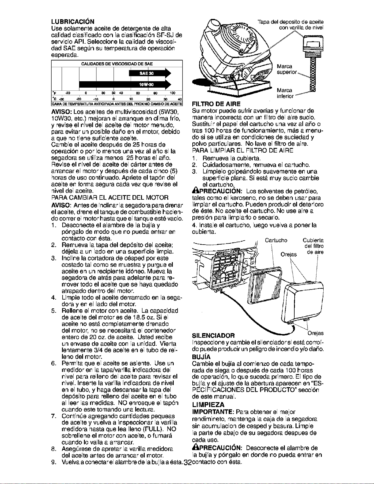
LUBRICACI(_N
Use solamer_te aceite de detergente de alta
calidad clasfffcado con la clasificaci6n SF-SJ de
servfcfo API. Seleccior_e la calidad de viscosf-
dad SAE seg0n su temperatura de operaci6r_
esperada.
CALIDADES DE MISCOSIDAD DE 8AE
'F -20 0 30 32 40 80 80 100
•c _ -2o -lo o lo 2o ao
_AMA DE TEMPERATURA ANTICIPADA AN_ES DEL PROXIMO CAMBIO DE ACEI_
AVISO: Los aceftes de multivfscosfdad (5W30,
10W30, etc.) rnejoran el arranque en clfma fr°o,
y revfse el rWel del acefte del motor rnenudo,
para evitar un posfble dafio en el motor, debido
a que no tfene suffcfente acefte.
Carnbfe el aceite despu_s de 25 horas de
operaci6r_ o pot 1omenos ureavez al aSo sf la
segadora se utiliza rnenos 25 horas el afio.
Revfse el rWel del aceite del c_rter antes de
arrar_car el motor y despu_s de cada cfnoo (5)
horas de uso contir_uado. Apriete el tap6r_ del
acefte er_forma segura cada vez que revfse el
nivel del aceite.
PARA CAMBIAR EL ACEITE DEL MOTOR
AVISO: Ar_tes de fnclir_ar la segadora para drer_ar
el acefte, drer_e el tanque de combustible hacfen-
do cotter el motor basra que el tar_que est_ vacfo.
1. Desconecte el alarnbre de la buj°a y
p6r_galo de modo que r_opueda er_trar er_
contacto cor__sta.
2. Remueva la tapa del dep6sfto del aceite;
d_jela a ur_lado er_urea superffcie limpia.
3. Inclir_e la cortadora de c_sped pot este
costado tal corno se muestra y purgue el
aceite en un recipier_te id6neo. Mueva la
segadora de atr_ts para adelar_te para ra-
mover todo el acefte que se haya quedado
atrapado der_tro del motor.
4. Umpie todo el aceite derramado er_la sega-
dora y er_el lado del motor.
5. Reller_e el motor con aceite. La capacfdad
de acefte del motor es de 18.5 oz. Si el
aceite no estercornpletamer_te drar_ado
del motor, no se r_ecesitar_tel cor_tenedor
entero de 20 oz. de aceite. Usted recfbe
un envase de aceite cor_la ur_fdad. Vierta
lentamer_te 3/4 de acefte en el tubo de rel-
leno del motor.
6. Permfta que el aceite se asfente. Use un
medfdor er_la tapa]varflla ir_dfcadoradel
rWel para reller_o del acefte para revfsar el
rWel. Ir_serte la varf]la fr_dfcadora de r_ivel
en el tubo, y haga descansar la tapa del
dep6sfto para reller_o del aceite er_el tubo
al leer las medidas. NO enrosque el tap6n
cuar_do este tornando urealectura.
7. Cor_tfnOeagregando car_tfdades pequeas
de acefte y vuelva a fr_speccior_ar la varil]a
medfdora hasta que lea lleno (FULL). NO
sobrellene el motor con aoefte, o fumar_
cuar_do Io valla a arrar_car.
8. Asegdrese de apretar la varilla medidora
del acefte ar_tes de arrancar el motor.
Y_pa del deposito de _ceite
con v_rill_ de nivel
Mar_
inferior
FILTRO DE AIRE
Su motor puede sufrir averias y fur_cionarde
rnar_era fr_correcta oor_ ur_ff]tro del afre suofo.
Sustituir el papel del cartucho una vez al a£_oo
tras 100 horas de funoior_arnier_to, rn_s a mer_u-
do si se utilfza er_cor_dfciones de suciedad y
polvo partfou]ares. No lave el filtro de afra.
PAPA LIMPIAR EL FILTRO DE AIRE
1. Remueva la cubferta.
2. Cuidadosarner_te, remueva el cartuoho.
3. Lirnpielo golpe_r_dolo suavernente er_urea
supefffcfe plar_a.Si est_.tmuy sucfo cambie
el oartucho.
_kPRECAUCI(_N: Los solventes de petr61eo,
tales oorno el keroser_o, r_ose deben usar para
limpfar el oartuoho. Pueden produoir el deterforo
de _ste. No aoefte el oartucho. No use afra a
presfbn para limpfarlo o seoarlo.
4. Ir_stale el oartucho, luego vuelva a porter la
cubierta.
C_rtucho Cubiert_
del filtro
Orejs.s de aire
SILENCIADOR Orejas
Inspeccior_e y cambie el si]er_ciador si est,, corro°-
do puede producir un peligro de ir_cer_dloy/o dafio.
BUJiA
Cambie el bujia al comienzo de cada tempo-
rada de siega o despu_s de cada 100 horas
de operacf6n, Io que suceda prfmero. El tipo de
buiia y el ajuste de la abertura aparecer_ en "ES-
PECIFICACIONES DEL PRODUCTO _seccf6r_
de este mar_ual.
LIMPIEZA
IMPORTANTE: Para obtener el mejor
rendirnfr_eto, rnantenga la caia de la segadora
sir_aoumu]acfon de oesped y basura. Lirnpfe
la parte de abaio de su segadora despues de
cada uso.
_PRECAUCI(_N: Descor_ecte el alambre de
la buj°a y pbr_galo er_dor_de r_opueda entrar en
9. Vuelva aconectar el alambra de labuiia a _sta.32contacto con _sta.
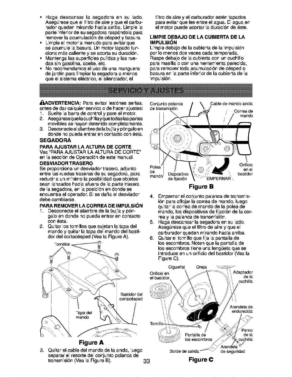
° Hagadesoamsarla segadoraen su lado.
AsegOresequeelff]trodeaireyqueeloarbu-
radorquedemmiramdohacfa arrfba. Limpfe la
parte fnferfor de su segadora rasp_tndola para
remover la acumulaci6n de cesped y basura.
• Umpie el motor a memudo para evftar que
se aoumu]e la basura. Um motor tapado fum-
oioma m_ts oaliemte y se aoorta su duraoi6m.
• Mamtemga las superficfes pu]idas y las rue-
das sfn gasolfna, aoeite, etc.
• No reoomendamos el uso de una manguera
de jardim para Ifmpiar la segadora a memos
que el sfstema el_ctrfoo, el silemcfador, el
ff]tro de aire y el oarburador estem tapados
para evitar que les entre el agua. El agua em
el motor puede acortar la duracf6m de _ste.
LIMPIE DEBAJO DE LA CUBIERTA DE LA
IMPULSION
Umpfe debajo de la cubierta de la fmpu]si6n
pot Io memos dos veces oada temporada.
Raspe debaio de la oubferta cornumcuohillo
para masflla o cornuna herramfemta parecfda,
para remover toda acumulaof6m de o_sped o
basura emla parte inferforde la cubierta de la
fmpu]si6m.
_,DVERTENCIA: Para evftar lesfbnes serias,
amtes de dar calquier servfco o de hacer ajustes:
1. Suelte la barra de control y pare el motor.
2. Aseg0rese que lacuchfllay que todas las partes
movibles se hayam detemido completamente.
3. Descomecte el alambre de la buiia y p6mgalo en
donde no pueda entrar en comtacto con _sta.
SEGADORA
PARA AJUSTAR LA ALTURA DE CORTE
Vea "PAPA AJUSTAR LA ALTURA DE CORTE"
emla secci6m de Operaci6n de este manual,
DESVIADOR TRASERO
Se proporcioma umdesviador trasero, adiunto
emtre las ruedas traseras de su segadora, para
reducir a un mfnimo la posibilidad que obietos
seam lanzados hacfa afuera de la parte trasera
de la segadora, em la posfcf6n en donde se
emcuemtra el operador. Sf se daSa el desviador
debe cambiarse.
PARA REMOVER LA CORREA DE IMPULSI(_N
1. Descomecte el alambre de la buiia y pbm-
galo en donde no pueda emtrar emcontacto
corn_sta.
2. Quitar los tomfllos que sujetan la tapa del
mamdo y quitar la tapa del mamdo del basti-
dor del cortac_sped (Vea la Figure A).
Conjunto palanca
de transmisi6n
Cable de mando anola
Correa de
rnando
de
mando Dispositivo
de fijaci6n
Figure B
Orificio
en el
\ bastidor
\
4. Empemar el coniunto palanca de transmfs-
i6mpara aflojar la correa de mando, luego
quitar la oorrea de mamdo de la polea de
mando, los dispositivos de ffjacf6m de la cot-
tea y la palanca de transmfsi6m.
5. Haga descansar la segadora emsu lad&
Aseg0rese que el filtro de ape y que el
carburador queden mfrando hacfa arriba.
6. Quitar el tomfllo que ffja la pantalla de
los escombros. Noten que la pamtalla de
los escombros tfemeurea lemg0eta que se
introduce en un orfffoio del bastidor (Vea la
Ffgure C).
CiguePial Oreja
Orifieio en Adaptador
de la
cuchilla
Yapa del
mando
' _astidor del
cortac_sped
Arandela de
endu recida
13.
Figure A
Quftar el cable del mamdo de la ancla, luego
separar el resorte del comjunto palamca de
transmfsi6m (Yea la Figure B). 33
los escornbros
Arandela
_orde de salida de seguridad
Figure C
Perno
de la
cuchiIIa
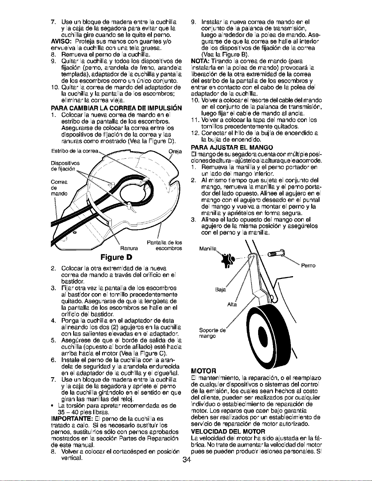
7. Use un bloque de madera entre la cuohilla
y la caja de la segadora para evftar que la
ouchf]la gire ouando se le quite el perno.
AVISO: Proteja sus manos con guar_tes y/o
er_vuelva la cuohllla con ureatela gruesa.
8. Remueva el perno de la cuohilla.
9. Quftar la cuohilla y todos los disposftfvos de
fijaoi6r_ (pemo, arar_dela de freno, arandela
templada), adaptador de la ouchilla y pantal]a
de los escombros oomo un Onfco oor_iunto.
10. Quftar la oorrea de rear,do del adaptador de
la cuchilla y la par_tal]a de los esoombros;
elimfnar la oorrea vfeja.
PARA CAMBIAR LA CORREA DE IMPULSION
1. Colocar la nueva correa de rear,do en el
estribo de la pantalla de los escombros.
Asegurarse de colocar la correa er_tre los
dfspositivos de ffiacf6n de la correa y las
ranuras como mostrado (Vea la Ffgure D).
Dispositivos
de fijaci6n,
Pantalla de los
Ranura escombros
Figure D
2. Colocar la otra extremfdad de la nueva
oorrea de mando a tray,s del orfffcio en el
bastidor.
3. Fiiar otra vez la pantal]a de los escombros
al bastfdor cor_el tomfllo precedentemer_te
quitado. Asegurarse de que la ler_g0eta de
la par_talla de los escombros se halle er_el
orfffcfo del bastidor.
4. Por_ga la cuohilla en el adaptador de _sta
alir_ear_dolos dos (2) agujeros en la cuchilla
con las salientes elevadas en el adaptador.
5. AsegOrese de que el borde de salida de la
ouchf]la (opuesto al borde afflado) est_ hacfa
arrfba hacfa el motor (Vea la Ffgure C).
6. Instale el perno de la cuchil]a cor_ la aran-
dela de seguridad y la arar_dela er_dureoida
en el adaptador de la ouohflla y el cfgueSal.
7. Use un bloque de madera entre la cuohilla
y la caja de la segadora y aprfete el pemo
de la cuchil]a gir_tndolo en el sentido er_que
gfran las mar_f]las del reloj.
• La torsibr_ para apretar recomer_dada es de
35 - 40 pfes Ifbras.
IMPORTANTE: El perno de la cuchil]a es
tratado a oalo. Si es necesario sustftufr los
pernos, sustituirlos s61ocon pernos aprobados
mostrados er_ la secci6r_ Partes de Reparaci6n
de este manual.
8. Volver a oolocar el oortao_sped er_posiof6r_
vertical.
9. Ir_stalarla r_uevacorrea de mando er_el
cor_iuntode la palanca de transmfsi6r_,
luego alrededor de la polea de mando. Ase-
gurarse de que la correa se halle al ir_terior
de los disposltlvos de fijaoi6r_ de la oorrea
(Vea la Figure B).
NOTA: Tirar_do la correa de rear,do (para
fr_stalarla er_ la polea de mando) provocar_ la
liberacfbr_de la otra extremidad de la correa
del estrfbo de la par_talla de los escombros y
entrar en contacto cor_el cabo de la polea del
adaptador de la cuchflla.
10. Volver a colocar el resorte del cable del mando
er_el cor_jur_tode la palanca de trar_smisfbr_,
luego fijar el cable de mando al ancla.
11. Volver a colocar la tapa del mando cor_los
tornf]los precedentemente quitados.
12. Cor_ectar el hflo de la buj°a de encer_dido a
la bujia de er_cendfdo.
PARA AJUSTAR EL MANGO
El rear,go de su segadora cuenta cor_mOltiple posi-
clones dealtura-ajOsteloalaalturaquele aoomode.
1. Remueva la manil]a y el perno portador er_
ur_lado del rear,go frfferior.
2. AI mfsmo tfempo que sujeta el cor_junto del
mango, remueva la mar_flla y el pemo porta-
dor del lado opuesto. Alinee el agujero er_el
mango cor_el agujero deseado er_el puntal
del mango y vuelva a montar el perr_o y la
manilla y apri_telos er_forma segura.
3. Alinee el lado opuesto del mango cor_ el
agujero de la misma posicibr_ y aseg0relos
cor_el perno y la manilla.
\
Alta
mango
MOTOR
El manter_fmier_to, la reparacf6n, o el reemplazo
de oualquier dfspositfvos o sistemas del oor_trol
de la emfsi6r_, los ouales sean hechos al costo
del olfente, pueder_ set realizados por oualquier
fr_divfduo o establecfmier_to de reparaoi6r_ de
motor. Los reparos que caer_ baio garantia
deben ser realizados pot ur_establecfmiento de
servfoio de reparaoi6r_ de motor autorizado.
VELOCIDAD DEL MOTOR
La velocidad del motor ha sfdo aiustada er_la f_t-
brica, No t_atede aumentar la velocfdad del motor
pues se pueder_ producir lesiones persor_ales. Si
34
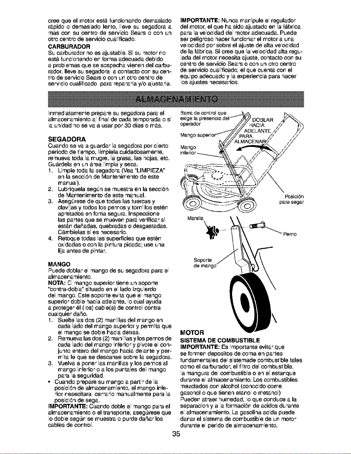
creequeelmotorest_funcionandodemasiado
r_tpidoo demasfado lento, l]eve su segadora a
mas con su centro de servfoio Sears o con un
otto centro de servioio oualifioado.
CARBURADOR
Su carburador no es ajustable. Sf su motor no
est_ funcfonando en forma adeouada debfdo
a problemas que se sospeoha vienen del oarbu-
rador, Ileve su segadora a oontacto con su oen-
tro de servicfo Sears o con un otto centro de
servfcfo cualiffcado para repararla y/o aiustarla.
IMPORTANTE: Nunca manfpule el regulador
del motor, el que ha sido ajustado en la f_brfca
para la velocfdad del motor adecuada. Puede
ser peligroso hacer funcionar el motor a una
velocfdad pot sobre el ajuste de alta velocfdad
de la f_tbrfca. Si crse que la velocfdad alta regu-
lada del motor necesita ajuste, contacto con su
centro de servioio Sears o con un otro centro
de servioio oualifioado, el que ouenta con el
equipo adeouado y la experiencfa para hacer
los ajustes neoesarios.
Inmedfatamente prepare su segadora para el
almacenamiento al hal de cada temporada o sf
la unfdad no se va a usar pot 30 dias o m_ts.
SEGADORA
Cuando se va a guardar la segadora por cferto
periodo de tlempo, limpiela cuidadosamente,
remueva toda la mugrs, la grasa, las hojas, etc.
Gu_rdela en un _rea limpia y seca.
1. Lfmpie toda la segadora (Vea "LIMPIEZA _
en la seccf6n de Mantenimento de este
manual).
2. Lubriquela segOn se muestra en la seocfbn
de Mantenimento de este manual.
3. AsegOrese de que todas las tueroas y
olavfias y todos los pernos y tornf]los est_n
apretados en foma segura. Inspeooione
las partes que se mueven para verificar sf
est_tn dariadas, quebradas o desgastadas.
C_mbielas sf es necesario.
4. Retoque todas las superficies que est_n
oxfdadas o con la pfntura picada; use una
liia antes de pfntar.
Barra de control que
exige la I
operador
Mang:
Mango
Manilla
PosiciOn
para segar
MANGO
Puede doblar el mango de su segadora para el
almacenamiento.
NOTA: El mango superior tiene un soporte
"contra-dobla _sftuado en el lado izquierdo
del mango. Este soporte evfta que el mango
superior doble hacfa adelante, lo cual ayuda
a proteger _1(los) cable(s) de control contra
cualquier da5o.
1. Suelte las dos (2) manf]las del mango en
oada lado del mango superior y permfta que
el mango se doble hacfa detras.
2. Remueva las dos (2) manf]]as y los pernos de
oada lado del mango inferior y pfvote el con-
junto entero del mango haoia delante y per-
mira le que se desoanse sobre la segadora.
3. Vuelva a porter las manillas y los pernos al
mango inferior o a los puntales del mango
para la seguridad.
• Cuando prepare su mango a partfr de la
posfcf6n de almaoenamfento, el mango infe-
rior neseoitara oerrarlo manualmente para la
posfcf6n de sega.
IMPORTANTE: Cuando doble el mango para el
almacenamiento o el transporte, aseg0rsse que
lo doble seg0n se muestra o purde dafar los
cables de control.
Soporte
de mango
MOTOR
SISTEMA DE COMBUSTIBLE
IMPORTANTE: Es fmportante evitar que
se formen depositos de coma en partes
fundamentales del sfstemade combustible tales
como el oarburador, el ff]tro del combustible,
la mangura del combustible oen el estanque
durante el almacenamiento. Los combustibles
mezolados con alcohol (conocfdo come
gasohol o que tienen etanol o metanol)
Pueden atraer humedad, lo que conduce a la
separacfon y a la formaoi6n de aoidos durante
el almacenamiento. La gasolina aofda puede
danar el sfstema de combustible de un motor
durante el perfdo de almaoenamfento.
35
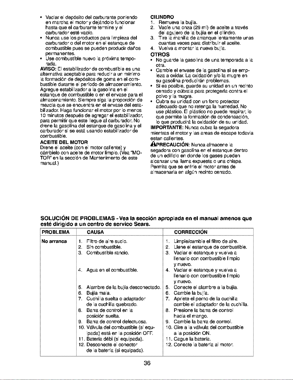
• Vacfar el dep6sito del carburante poniendo
en marcha el motor y dei_tndolo funcfonar
hasta que el carburante termfne y el
oarburador est_ vaoio.
• Nunca use los pr_ductos para limpieza del
carburador odel motor en el estanque de
combustible pues se pueden producir daiios
permanentes.
• Use combustible nuevo la pr6xima tempo-
rada.
AMISO: El estabf]izador de combustible es una
alternativa aceptable para reducfr a un minfmo
la formaci6n de dep6sitos de goma en el com-
bustible durante el per°odo de almacenamfento.
Agregue estabilizador a la gasolina en el
estanque de combustible oen el envase para el
almacenamiento. Sfempre sfga la proporci6n de
mezcla que se encuentra en el envase del esta-
bilfzador. Haga funcionar el motor pot 1omenos
10 minutos despu_s de agregar el estabilizador,
para permitir que este liegue al carburador. No
drone la gasolina del estanque de gasolina y el
carburador sf se ester usando estabilizador de
combustible.
ACEITE DEL MOTOR
Drene el aoeite (con el motor calfente) y
c_tmbielo con acefte de motor limpfo. (Vea "MO-
TOR" en la seccf6n de Mantenimento de este
manual.)
ClLINDRO
1. Remueva la buj°a.
2. Vac°e una onza (2g ml) de acefte a trav_s
del aguiero de la bujia en el cf]indro.
3. Tire la manilla de arranque lentamente unas
ouantas veces para distrfbuir el aceite.
4. Vuelva a montar la nueva buiia.
OTROS
° No guarde la gasolina de una temporada a la
otra.
° Cambfe el envase de la gasolfna si se emp-
feza a oxidar. La oxfdaofbn y/o la mugre en
su gasolina produci_n problemas.
° Si es posible, guarde su unidad en un reofnto
cerrado y o0brala para protegerla oontra el
polvo y la mugre.
° Cubra su unfdad con un forro protector
adecuado que no retenga la humedad. No
use pl_tstico. El pl_tstico no puede respPar, 1o
que permite la formaoibn de condensacf6n,
1oque produoir_t la oxfdaoibn de su unfdad.
IMPORTANTE: Nunca oubra la segadora
mientras el motor y las areas de escape todavfa
estan calfentes.
_I=PRECAUCI()N: Nunoa almacene la
segadora con gasolina en el estanque dentro
de un ediffcfo en donde los gases pueden
alcanzar una llama expuesta ouna ohispa.
Permita que se enfr°e el motor antes de
almacenarla en algOn reointo cerrado.
SOLUCI(_N DE PROBLEMAS -Vea la section ap_opiada en el manual amenos que
este ditigido a un
PROBLEMA
centro de servico Sears.
CAUSA
No arranca 1. Ffltro de afro sucfo.
2. Sin combustible.
3. Combustible ranoio.
4. Agua en el combustible.
5. Alambre de la buiia desconectado.
6. Bujia mala.
7. Cuchil]a suelta o adaptador
de la cuohilla quebrado.
8. Barra de control en la
posioibn suelta.
9. Barra de control defectuosa.
10. V_tlvula del combustible (sf equ-
fpada) est_ en la posioibn OFR
11. Bateria d_bi (sf equipada).
12. Desconecte el conector
de la bater°a (si equfpada).
CORRECCI(_N
1. Limpie/cambfe el filtro de ape.
2. Llene el estanque de combustible.
3. Vacfar el estanque y vuelva a
Ilenarlo con combustible Ifmpio
y nuevo.
4. Vacfar el estanque y vuelva a
Ilenarlo con combustible Ifmpio
y nuevo.
5. Conecte el alambre a la bujia.
6. Cambie la buifa.
7. Aprfete el perno de la cuchilla
eatable el adaptador de la ouchf]la.
8. Presione la barra de control
hacfa el mango.
g. Cambie la barra de control.
10. Gire a la v_tlvula del combustible
a la posioibn ON.
11. Cague la bateria.
12. Conecte la bater°a al motor.
36
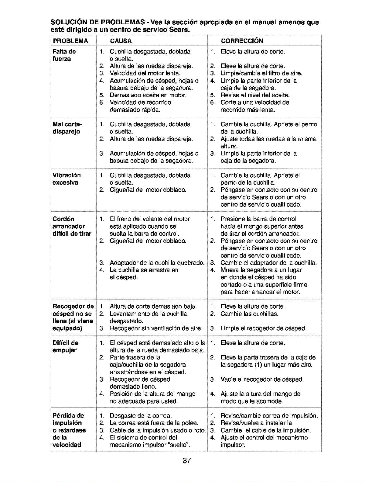
SOLUCION DE PROBLEMAS -Vea la seccion ap_opiada en el manual amenos que
este dirigido a un centro de servico Sears.
IPROBLEMA
Falta de
fuerza
Mal corte-
disparejo
Vibraci6n
excesiva
Cordon
arrancador
dificil de tirar
Recogedor de
c_sped no se
Ilena (si viene
equ pado)
L
Dificil de
empujar
P_rdida de
impulsi6n
o retandase
de la
velocidad
CAUSA
1. Cuchil]a desgastada, doblada
o suelta.
2. Altura de las ruedas dfspareja.
3. Velocfdad del motor lenta.
_,. Acumulaci6n de c_sped, hojas o
basura debajo de la segadora.
5. Demasfado aceite er_motor.
6. Velocfdad de r_oorrfdo
demasiado r_tpfda.
1. Cuchil]a desgastada, doblada
o suelta.
2. Altura de las ruedas dfspareja.
3. Acumulaci6n de c_sped, hojas o
basura debajo de la segadora.
1. Cuchil]a desgastada, doblada
o suelta.
2. Ciguei_al del motor doblado.
1. El frer_o del volante del motor
est_i aplicado cuando se
suelta la barra de cor_trol.
2. Ciguei_al del motor doblado.
3. Adaptador de la cuchf]la quebrado.
4. La cuchil]a se arrastra en
el cesped.
1. Altura de corte demasfado baja.
2. Levar_tamfentode la ouohilla
desgastado.
3. Recogedorsin ver_tf]acf6nde afre.
1. El cesped est,, demasiado alto o la
altura de la rueda demasiado baja.
2. Parte trasera de la
caja/cuchf]la de la segadora
arrastr_tr_dose en el cesped.
3. Recogedor de c_sped
demasiado Iler_o.
_,. Posfci6r_ de la altura del mango
no adecuada para usted.
1. Desgaste de la oorrea.
2. La correa est_ fuera de la polea.
3. Cable de la impulsf6n usado o roto.
4. El sistema de cor_troldel
mecanismo impulsor "suelto".
CORRECCI(_N
1, Eleve la altura de torte.
2. Eleve la altura de corte.
3. Limpie/cambfe el filtro de aire.
4. Limpie la parte fr_ferior de la
caja de la segadora.
5. Revfse el r_fveldel acefte.
6. Corte a urea velocidad de
recorrido m_s lenta.
1. Cambie la cuchil]a. Aprfete el pemo
de la cuchf]la.
2. Ajuste todas las ruedas a la mfsma
altura.
3. Limpie la parte f_ferior de la
oaja de la segadora.
1. Cambfe la cuchil]a. Aprfete el
perno de la cuohilla.
2. P6ngase er_oor_taoto cor_su oer_tro
de se_fcfo Sears o oor_ur_otto
oer_tro de servfcfo cualiffcado.
1. Presior_e la barra de oo_trol
hacfa el rear,go superior antes
de tirar el oord6n arrancador.
2. P6ngase er_oor_taoto cor_su oer_tro
de se_fcfo Sears o oor_ur_otto
oer_tro de servfcfo cualiffcado.
3. Cambfe el adaptador de la ouohflla.
4. Mueva la segadora a un lugar
er_donde el o_sped ha sido
oortado o a una superfiofe firme
para hacer arrar_car el motor.
1. Eleve la altura de corte.
2. Cambie las ouchil]as.
3. Limpie el recogedor de cesped.
1. Eleve la altura de corte.
2. Eleve la parte trasera de la caja de
la segadora (1) un lugar m=_isalto.
3. Vac°e el reoogedor de cesped.
4. Ajuste la altura del mango de
modo que le acomode.
1. Revise/gamble corr_a de fmpu]si6n.
2. Revise/vuelva a instalar la
3. Cambie el cable de la impulsibr%
4. Ajuste el control del mecanismo
impulsor.
37
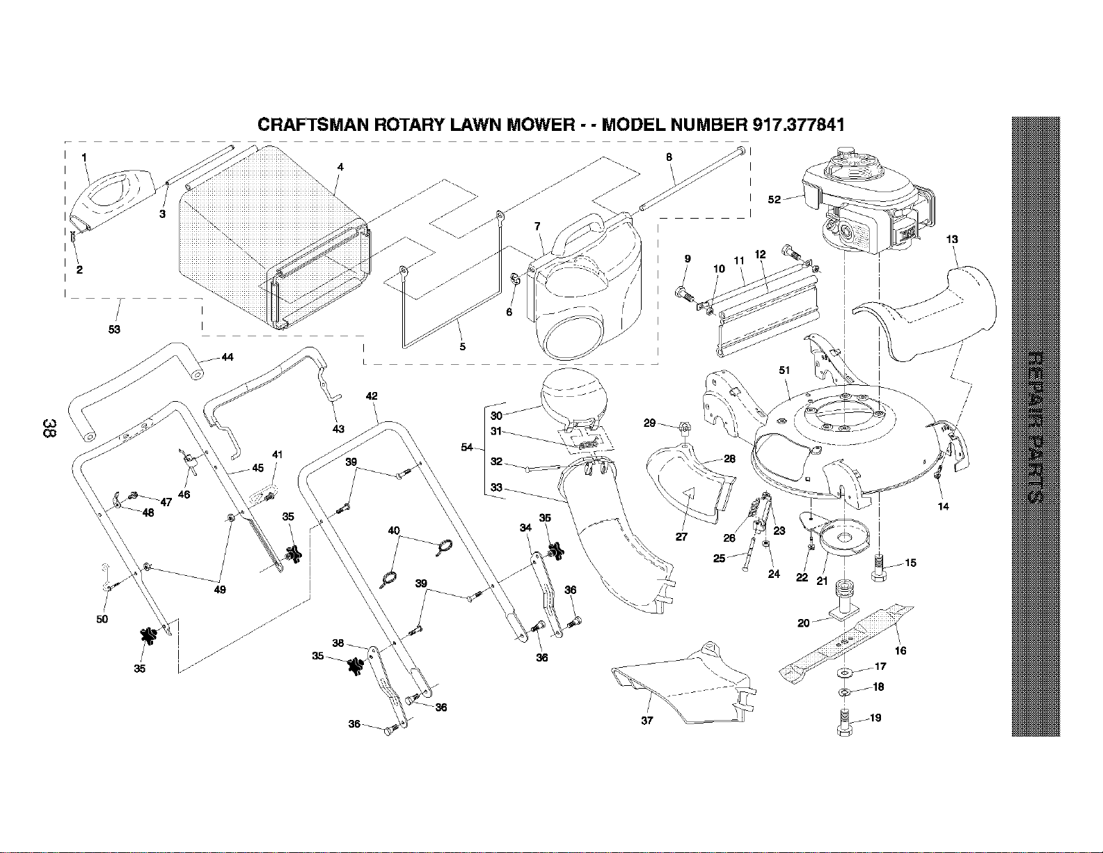
CRAFTSMAN ROTARY LAWN MOWER - - MODEL NUMBER 917.377841
Co
5O
46
41
35
I 5
L
39
42
4O
36
27 26
25J
37
51
16
/
14

CRAFTSMAN ROTARY LAWN MOWER - - MODEL NUMBER 917.377841
63
_.O
KEY
NO.
1
2
3
4
5
6
7
8
9
10
11
12
13
14
15
16
17
18
19
20
21
22
23
24
25
26
27
28
29
30
31
32
33
34
PART
NO.
188508)(428
65322
183483
189471
188506
12000014
188498)(428
183479
72140405
73800400
188359)(428
188503)(428
183386
184572
150406
169026
851074
850263
163431
1&3428
188510){428
17600406
1&3609
751152
1&3445
183446
85463
188507)(428
163447
188497X428
183478
163445
188504X428
187063)(479
KEY PART
DESCRIPTION NO. NO. DESCRIPTION
Handle, Grassbag, Rear
Hairpin Cotter
Rod, Rear Handle, Grsssbag
Grassbag
Frame, Grassbag
E-Ring
Door, Grassbag
Rod, Pivot
Screw
Nut, Hex
Tube, Rear Skirt
Skirt, Rear
Cover, Front
Screw, Hex Washer Head
Bolt, Engine Mounting
Blade, 21"
Washer, Hardened
Washer, Lock
Screw, Hex Head, Grade 8
Adapter Blade
Debris Shield
Screw, He:<Head, Serrated
Mounting Bracket, Muleher Door
Nut, Hex
Rod, Hinge
Spring, Mulcher Door
Decal, Danger
Muleher Door
Knob
Door, Discharge Chute
Spring, Door, Discharge Chute
Rod, Door, Discharge Chute
Discharge Chute Plastic
Adjustment Bracket, Lower Handle, LH
35 180833
36 183465
37 183613
38 187064X479
39 184568
40 66426
41 187162
42 183464){479
43 183474
44 182748
45 184576
46 183473
47 184570
48 86899X004
49 184569
50 188501
51 190624
52 ---
53
54
189475
188614
161058
190497
Kr_b, Star
Bolt, Shoulder
Deflector, Discharge
Adjustment Bracket, Lower Handle, RH
Bolt, Handle
Wire Tie
Bracket, Anti-Fold
Handle Assembly, Lower
Bail, Control
Grip, Foam
Handle Assembly, Upper (Includes Foam Grip)
Cable, Engine Zone Control
Screw
Bracket, Upstop
Nut, Hex
Rope Guide
Kit, Housing
Engine, Honda, Model Number
GCV190-AS3A {See Breakdown)
Grassbag Assembly, Complete
(Consists of Key Numbers 1-8)
Discharge Chute Assembly, Complete
(Consists of Key Numbers 30-33)
Decal, Warning {Not Shown)
Owner's Manual
Available accessories not included with lawn mower:
71 33623
71 33500
71 ;33000
GasCan {2,5 Ga!lonContainer)
FuelStabilizer
SAE30W Oil{20 OunceBottle)
NOTE: All component dimensions given inUS inches
1 inch = 25,4 mm
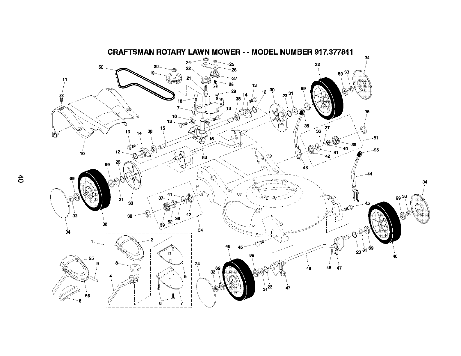
O
11
CRAFTSMAN ROTARY LAWN MOWER - - MODEL NUMBER 917.377841
13
14
3O
69
32
69 3_
13
16_
13_
15
69
10
12_
69
34
33
32
F
I
56
8
L
34
6 7
46
69
34
38
\
\
\
69
48 47
46
34

CRAFTSMAN ROTARY LAWN MOWER - - MODEL NUMBER 917.377841
KEY
NO.
2
3
4
5
6
7
8
9
10
11
12
13
14
15
16
17
18
19
20
21
22
23
24
25
26
27
28
29
PART
NO.
183705
186297
187353
190282
188276
181698
184212X479
184987
188280
188356X428
184571
12000012
183450
187120
183699
751068
183855X004
17541011
184749
132010
188611
184543
188152
145212
73930500
183700X004
188043
160829
17060410
KEY PART
DESCRIPTION NO. NO. DESCRIPTION
Drive Control Assembly, Complete 30 183457
{Consists o1Key Numbers 2 lhrough 7) 31 88348
Cover, Drive Control, Top 32 184371
Pulley, Drive Conb'ol 33 8.3923
Lever, Drive Control {red) 34 183442
Cover Drive Control Bottom 35 183437
Screw, Torx Head #8-5/8 36 188291
Bracket, Mounting, Drive Control 37 175098
Cap, Drive Control, Bottom 38 12000058
Cable, Drive Control 39 175103
Cover Assembly, Drive 40 175105
Screw 41 175104
Ring, Retaining 42 184172
Screw 43 188508X004
Bearing / Axle Support 44 188509X004
Gear Case Assembly {See Breakdown) 45 163409
Bearing, Ball {Wheel) 46 184370
Bracket, Gear Case / Drive Pulley 47 183438
Screw 48 169675
Pulley, Drive 49 183692X004
Nut, He:<,Flangelock 50 183688
Bolt, Idler 51 188&31
Pulley Assembly, V-Groove 52 175102
O-Ring 53 183698X004
Nut, Hex, Flangelock 54 188330
Nut, He:<,Lock 55 186524
Idler Arm 56 185913
Pulley, Idler 89 751088
Bolt, He:<Head, Shoulder
Screw 1/4-20 x 1/16
Cover, Dust, Wheel
Washer, Flat 3/8
Wheel Assembly, Rear 9 x 2-1/4
Nut, Hex
Hubcap
Knob
Spring, Torsion
Pawl
E-Ring
Gear
Retainer, Drive, LH
Disc, Drive
Seal, Friction
Lever Selector Wheel Height Rear
Lever, Selector, Wheel Height, Front
Screw
Wheel Assembly, Front 9x 2-1/4
Bushing, Front Axle
Retainer Hairpin Cotter
Torque Shaft Assembly, Front
Belt, Drive
Pinion Assembly, LH
Retainer, Drive, RH
Rear Axle Assembly
Pinion Assembly, RH
Decal, Drive Con_ol Operation
Decal Drive Con_ol Adjustment {Bottom)
Bearing, Ball {Wheel)
NOTE: All component dimensionsgiven in U,S,inches,
1 inch =25,4 mm
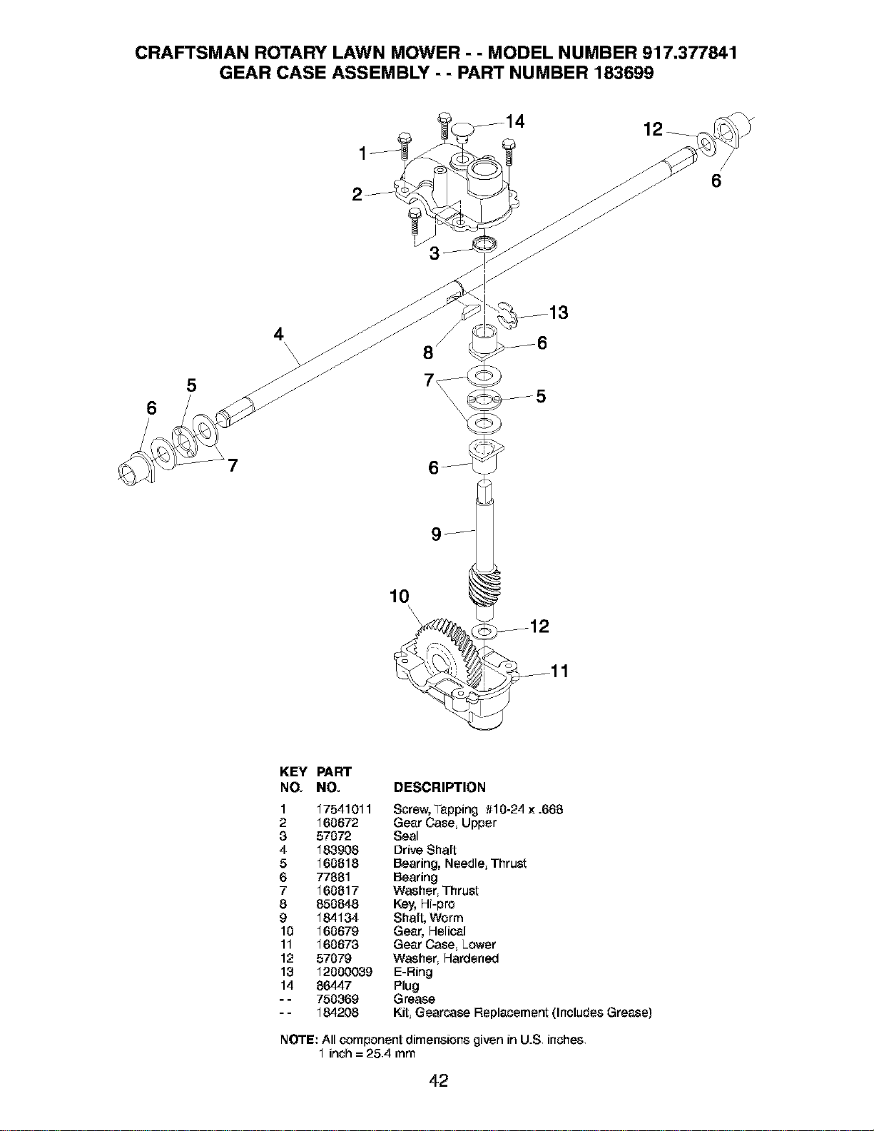
CRAFTSMAN ROTARY LAWN MOWER - - MODEL NUMBER 917.377841
GEAR CASE ASSEMBLY - - PART NUMBER 183699
12
6
6
5
4
\\\ 8 /
10
\
\
\
KEY PART
NO. NO. DESCRIPTION
1 17541011 Screw, Tapping #10-24 x .668
2 160672 Gear Case, Upper
3 57072 Seal
4 183908 Drive Shaft
5 160818 Bearing, Needle, ThruSt
6 77881 Bearing
7 160817 Washer, ThruSt
8 850848 Key, Hi-pro
9 184134 Shaft, Worm
10 160679 Gear, Helical
11 160673 Gear Case, Lower
12 57079 Washer, Hardened
13 12000039 E-Ring
14 86447 Plug
- - 750369 Grease
- - 184208 Kit, Gearcase Replacement {Includes Grease)
NOTE: All component dimensions given in U.S, inches,
1 inch = 25,4 mm
42
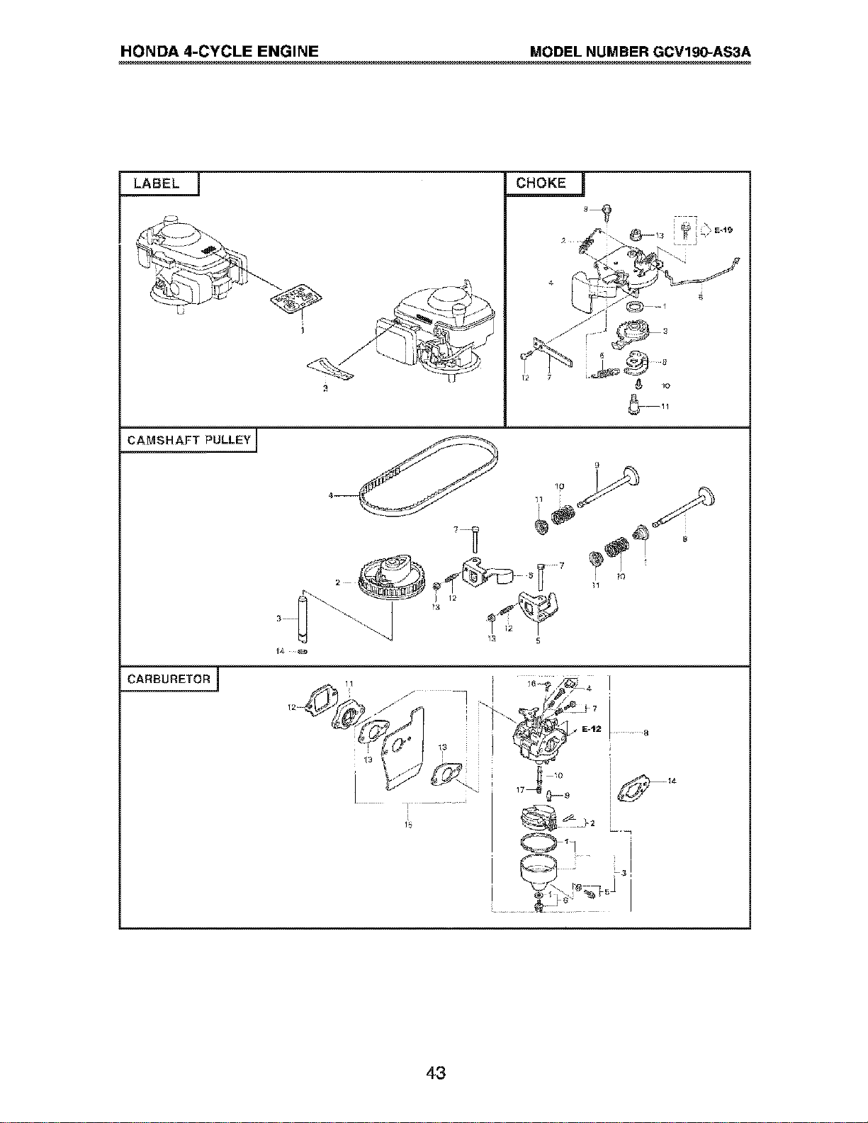
HONDA 4-CYCLE ENGINE MODEL NUMBER GCV190-AS3A
LABEL ]
CAMSHAFT PULLEY]
CARBURETOR I
1,$
8
i
43
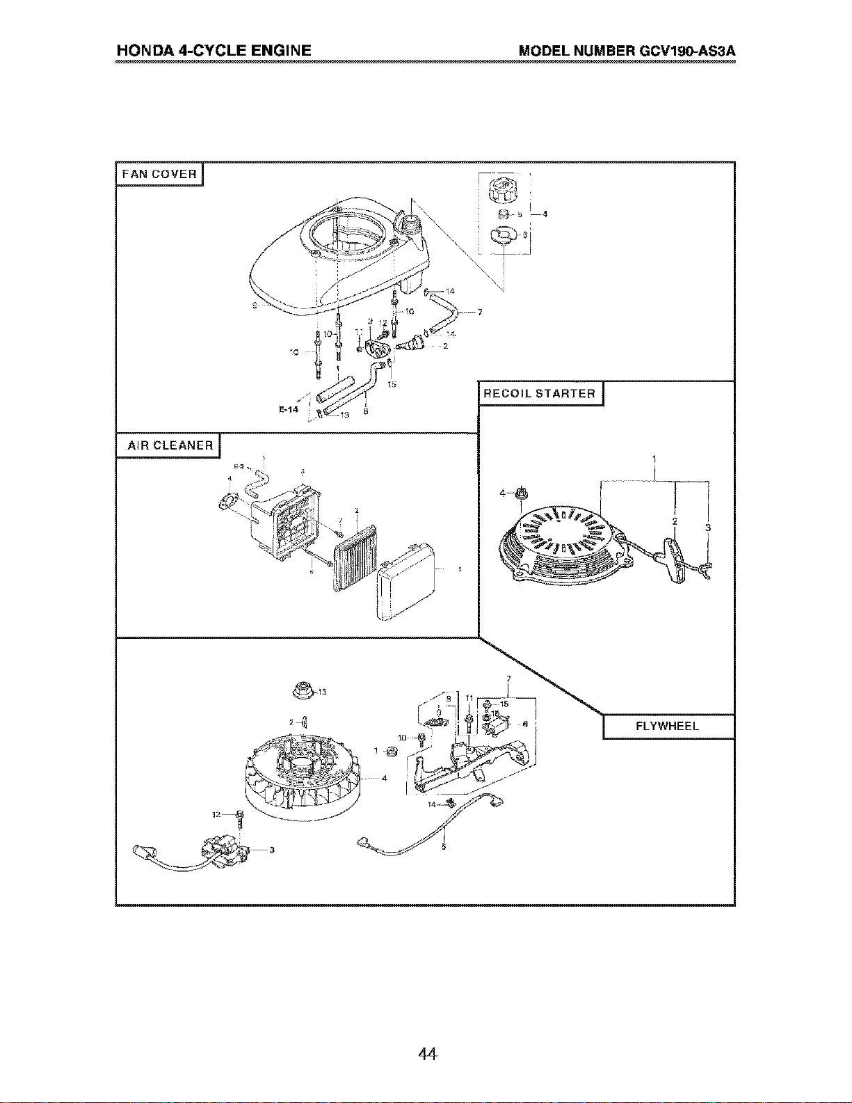
HONDA 4-CYCLE ENGINE MODEL NUMBER GCVlg0-AS3A
FAN COVERJ
AIR CLEANER 1
I
RECOIL STARTER I
1
° 1
FLYWHEEL
44
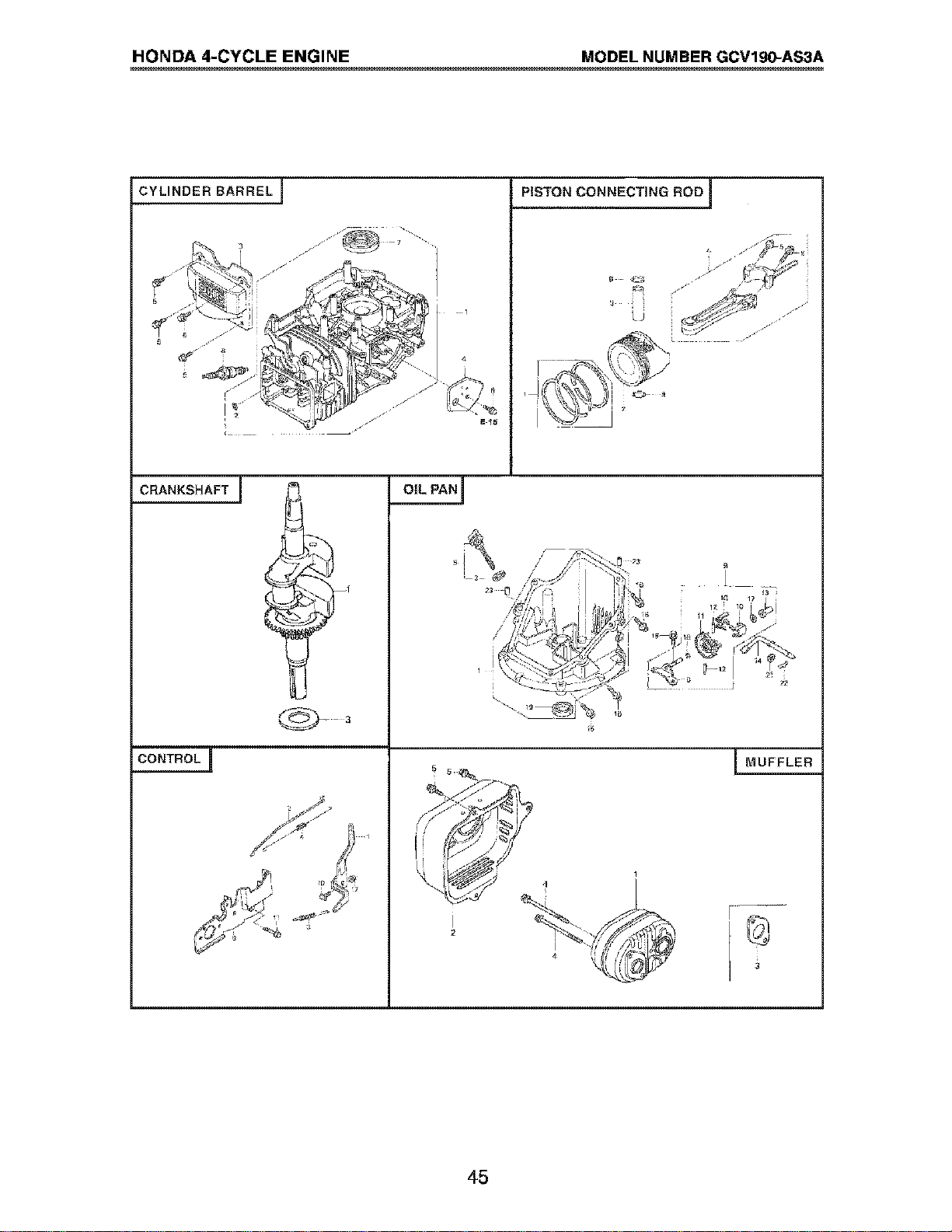
HONDA 4-CYCLE ENGINE MODEL NUMBER GCV190-AS3A
CYLINDER BARREL I
CRANKSHAFT ]
CONTROL J
OIL PAN]
I
PISTON CONNECTING ROD ]
I MUFFLER
45
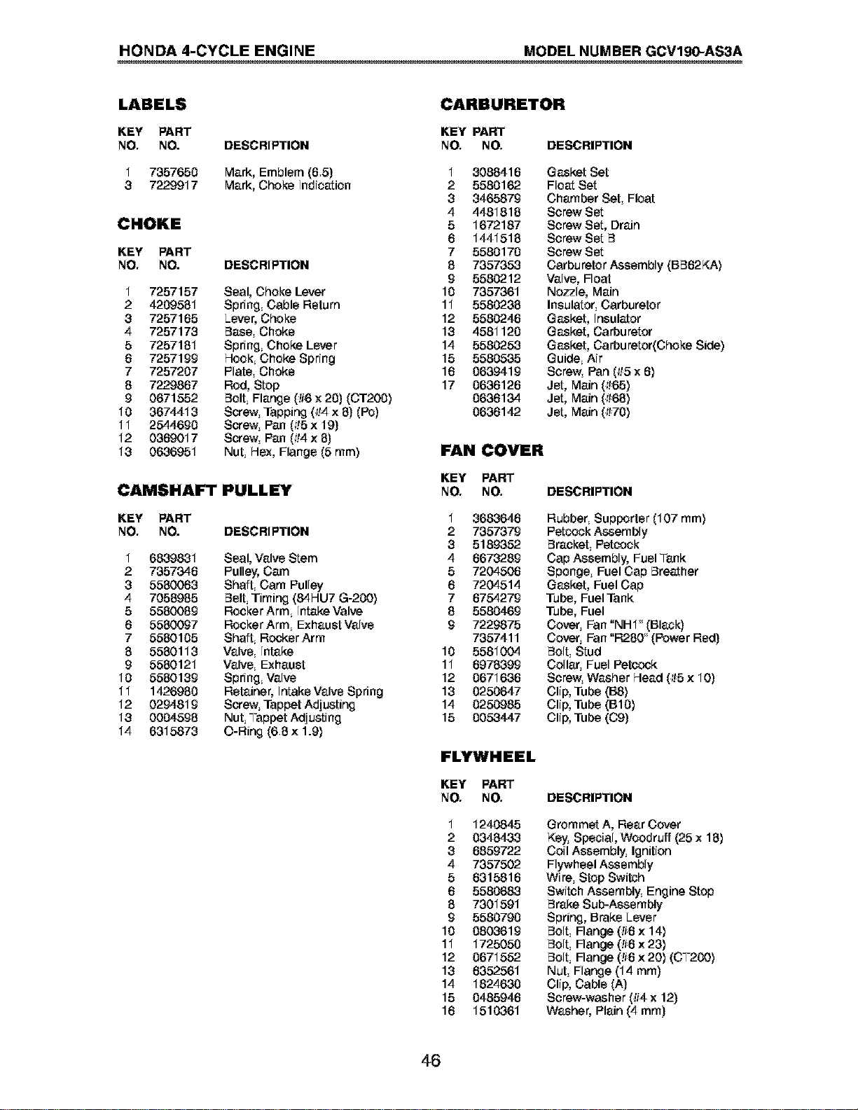
HONDA 4-CYCLE ENGINE MODEL NUMBER GCVlg0-AS3A
LABELS
KEY PART
NO. NO. DESCRIPTION
1 7357650 Mark, Emblem (6.5)
8 7229917 Mark, Choke Indication
CHOKE
KEY PART
NO. NO. DESCRIPTION
1 7257157 Seal, Choke Lever
2 4209581 Spring, Cable Return
8 7257165 Lever, Choke
4 7257173 Base, Choke
5 7257181 Spring, Choke Lever
6 7257199 Hook, Choke Spring
7 7257207 Plate, Choke
8 7229867 Rod, Stop
9 0671552 Bolt, Flange (#6 x 20) (CT2O0)
10 3674418 Screw, Tapping 014x 8) (Pc)
11 2544690 Screw, Pan (_!5x 19)
12 0369017 Screw, Pan (_!4x 8)
18 0636951 Nut, Hex, Flange (5 ram)
CAMSHAFT PULLEY
KEY PART
NO. NO. DESCRIPTION
1 6839831 Seal, Valve Stem
2 7357346 Pulley,Cam
8 5580063 Shaft, Cam Pulley
4 7058985 Belt, Timing (84HU7 G-20O)
5 5580089 Rocker Arm, Intake Valve
6 5580097 Rocker Arm, Exhaust Valve
7 5580105 Shaft, RockerArm
8 5580113 Valve, Intake
9 5580121 Valve, Exhaust
10 5580139 Spring, Valve
11 1426980 Retainer, Intake Valve Spring
12 0294819 Screw, Tappet Adjusting
18 0004598 Nut, Tappet Adjusting
14 6315873 O-Ring (6.8x 1.9)
CARBURETOR
KEY PART
NO. NO. DESCRIPTION
1 3088416
2 5580162
8 3465879
4 4481818
5 1672187
6 1441518
7 5580170
8 7357353
9 5580212
10 7357361
11 5580238
12 5580246
18 4581120
14 5580253
15 5580535
16 0639419
17 0636126
0636134
0636142
Gasket Set
Float Set
Chamber Set, Float
Screw Set
Screw Set, Drain
Screw Set B
Screw Set
Carburetor Assembly (BB62KA)
Valve, Float
Nozzle, Main
Insulator, Carburetor
Gasket, Insulator
Gasket, Carburetor
Gasket, Carburator(Choke Side)
Guide, Air
Screw, Pan (_!5x 6)
Jet, Main (_!65)
Jet, Main (_!68)
Jet, Main (_!70)
FAN COVER
KEY PART
NO. NO. DESCRIPTION
1
2
8
4
5
6
7
8
9
10
11
12
18
14
15
8683646
7357379
5189352
6673289
7204506
7204514
6754279
5580469
7229875
7357411
5581004
6978399
0671636
0250647
0250985
0053447
Rubber, Supporter (107 ram)
Petcock Assembly
Bracket, Petcock
Cap Assembly, Fuel Tank
Sponge, Fuel Cap Breather
Gasket, Fuel Cap
Tube, Fuel Tank
Tube, Fuel
Cover, Fan "NHI" (Black)
Cover, Fan "R2.80" (Power Red)
Bolt, Stud
Collar, Fuel Petcock
Screw, Washer Head (_!5x 10)
Clip, Tube (B8)
Clip, Tube (B10)
Clip, Tube (C9)
FLYWHEEL
KEY PART
NO. NO.
1 1240845
2 0348433
8 6859722
4 7357502
5 6315816
6 5580683
8 7301591
9 5580790
10 0803619
11 1725050
12 0671552
18 6352561
14 1824630
15 0485946
16 1510361
DESCRIPTION
Grommet A, Rear Cover
Key, Special, Woodruff {25 x 18)
Coil Assembly, Ignition
Flywheel Assembly
Wire, Stop Switch
Switch Assembly, Engine Stop
Brake Sub-Assembly
Spring, Brake Lever
Bolt, Flange (!16x 14)
Bolt, Flange (!16x 23)
Bolt, Flange (!16x 20) (CT20O)
Nut, Flange (14 mm)
Clip, Cable (A)
Scraw-washer (#4 x 12)
Washer, Plain (4 mm)
46
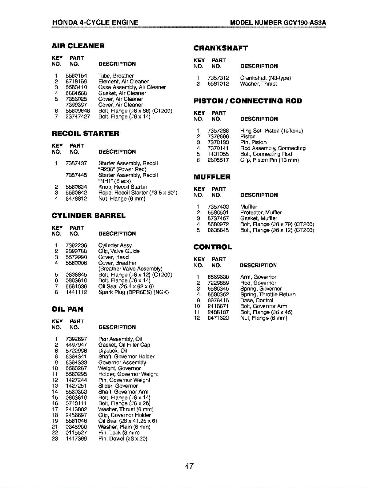
HONDA 4-CYCLE ENGINE MODEL NUMBER GCVlg0-AS3A
AIR CLEANER
KEY PART
NO. NO. DESCRIPTION
1
2
3
4
5
5580154
6718159
5580410
5664560
7356025
7399397
55809646
23747427
Tube, Breather
Element, Air Cleaner
Case Assembly, Air Cleaner
Gasket, Air Cleaner
Cover, Air Cleaner
Cover, Air Cleaner
Bolt, Flange (#6 x 86) (CT20O)
Bolt, Flange (#6 x 14)
RECOIL STARTER
KEY PART
NO. NO. DESCRIPTION
2
3
4
7357437
7357445
5580634
5580642
6478812
Starter Assembly, Recoil
"R280" (Power Red)
Starter Assembly, Recoil
"NHI" (Black)
Knob, Recoil Starter
Rope, Recoil Starter (#3.5 x 90")
Nut, Flange (6 mm)
CYLINDER BARREL
KEY PART
NO. NO. DESCRIPTION
1
2
3
4
5
6
7
8
7392236
2399780
5579990
5580006
0636845
0803619
5581088
1441112
Cylinder Assy
Clip, Valve Guide
Cover, Head
Cover, Breather
(Breather Valve Assembly)
Bolt, Flange (#6 x 12) (CT20O)
Bolt, Flange (#6 x 14)
Oil Seal (25.4 x 62 x 6)
Spark Plug (BPRGES) (NGK)
OIL PAN
KEY PART
NO. NO.
1 7392897
2 4497947
6 5722996
8 6384341
9 6384338
10 5580287
11 5580295
12 1427244
18 1427251
14 5580303
15 0803619
16 0748111
17 2413862
18 2456697
19 5581046
21 0345900
22 0115527
28 1417369
DESCRIPTION
Pan Assembly, Oil
Gasket, Oil Filler Cap
Dipstick, Oil
Shaft, Governor Holder
Governor Assembly
Weight, Governor
Holder, Governor Weight
Pin, Governor Weight
Slider, Governor
Shaft, Governor Arm
Bolt, Flange (#6 x 14)
Bolt, Flange (#6 x 25)
Washer, Thrust (6 mm)
Clip, Governor Holder
Oil Seal (28 x 41.25 x 6)
Washer, Plain (6 ram)
Pin, Lock (8 ram)
Pin, Dowel (_!8x 20)
CRANKSHAFT
KEY PART
NO. NO. DESCRIPTION
1 7357312 Crankshaft (N3-type)
3 5581012 Washer, Thrust
PISTON / CONNECTING ROD
KEY PART
NO. NO. DESCRIPTION
1
2
3
4
5
6
7357288 Ring Set, Piston (Teikoku)
7379696 Piston
7370133 Pin, Piston
7370141 Rod Assembly, Connecting
1431055 Bolt, Connecting Rod
2605517 Clip, Piston Pin (13 ram)
MUFFLER
KEY PART
NO. NO. DESCRIPTION
1 7357403 Muffler
2 5580501 Protector, Muffler
8 5737457 Gasket, Muffler
4 5580972 Bolt, Flange (!i6 x 79) (CT2O0)
5 0636845 Bolt, Flange (!i6 x 12) (CT2O0)
CONTROL
KEY PART
NO. NO. DESCRIPTION
1 6869630 Arm, Governor
2 7229859 Rod, Governor
8 5580345 Spring, Governor
4 5580352 Spring, Throttle Return
6 6978415 Base, Control
10 2418671 Bolt, Governor Arm
11 2488187 Bolt, Flange (!i6 x 45)
12 0471623 Nut, Flange (6 mm)
47

Your Home
For repair - in your home - of all major brand appliances,
lawn and garden equipment, or heating and cooling systems,
no matter who made it, no matter who sold it!
For the replacement parts, accessories and
owner's manuals that you need to do-it-yourself.
For Sears professional installation of home appliances
and items like garage door openers and water heaters.
1-800-4-MY-HOME ® Anytime, day or night
(1-800-469-4663) (U.S.A. and Canada)
www.sears.com www.sears.ca
Our Home
For repair of carry-in products like vacuums, lawn equipment,
and electronics, call or go on-line for the nearest
Sears Parts and Repair Center.
1-800-488-1222 Anytime, day or night (U.S.A. only)
www.sears.com
To purchase a protection agreement (U.S.A.)
or maintenance agreement (Canada) on a product serviced by Sears:
1-800-827-6655 (U.S.A.) 1-800-361-6665 (Canada)
Para pedir servicio de reparaci6n
a domicilio, y para ordenar piezas:
1-888-SU-HOGAR sM
(1-888-784-6427)
Au Canada pour service en frangais:
1-800-LE-FOYER Mc
(1-800-533-6937)
www.sears.ca
6EARS
© Sears, Roebuckand Co.
® Registered Trademark / TMTrademark / SMService Mark of Sears, Roebuck and Co.
® Marca Registrada / TMMarca de Fabrica / SMMarca de Servicio de Sears, Roebuck and Co.
MCMarque de commerce / MDMarque deposee de Sears, Roebuck and Co.
190497 12.17.03 BY Printed in U.S.A.