Loading ...
Loading ...
Loading ...
22
20302381
Designer Series Direct Vent Gas Fireplace
The Vent Graph, showing the relationship between vertical
and horizontal side wall venting, will help to determine the
various dimensions allowable. Figure 18
Minimum clearance between vent pipes and combustible
materials is 3" on top and 1" from bottom and sides unless
otherwise noted (Exception: Outside wall with restop: 1"
all around pipes are allowed). If the vertical run is 7.5 feet
or more, from the oor of the replace, the clearance is 1"
on all sides of the horizontal run.
When vent termination exits through foundations less than
20" below siding outcrop, the vent pipe must be ush with
the siding.
It is best to locate the replace in such a way that minimizes
the number of offsets and horizontal vent length.
The horizontal vent run refers to the total length of vent
pipe from the ue collar of the replace (or the top of the
Transition Elbow) to the face of the nished outside wall
or the mounting ange of the termination.
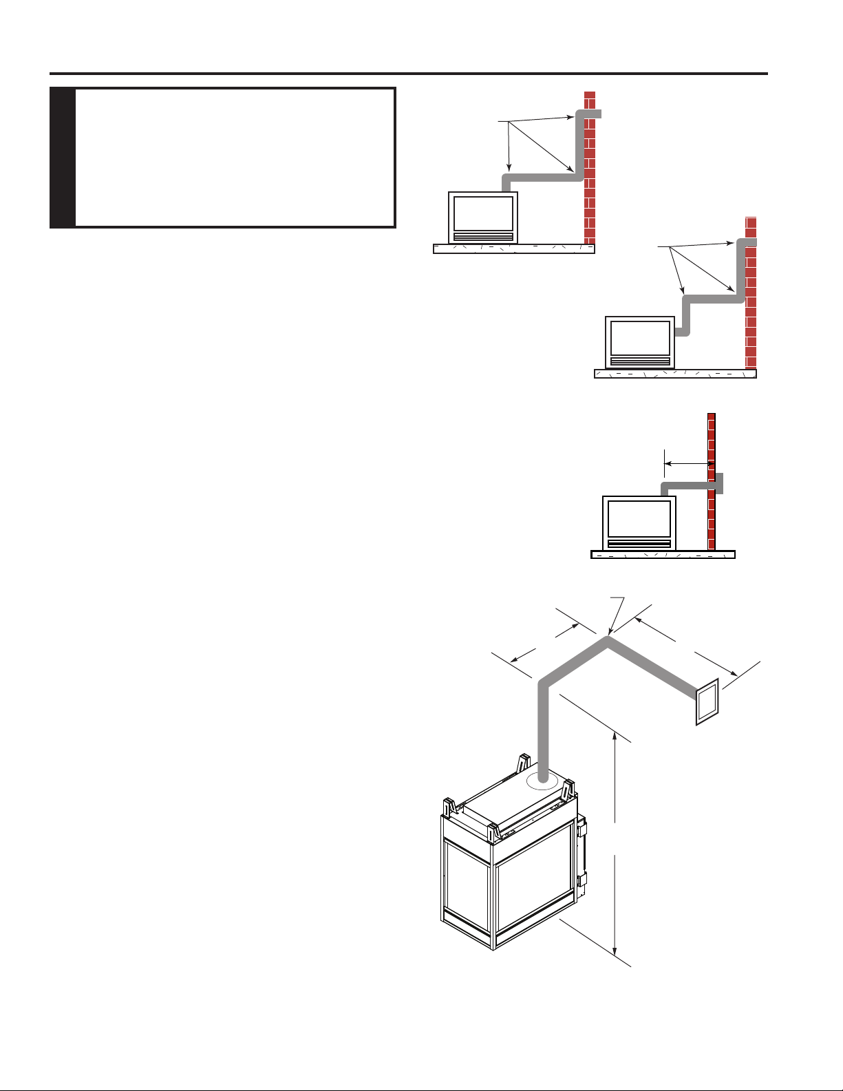
• The maximum number of 90° elbows per side wall
installation is three (3). Figure 25
• If a 90° elbow is tted directly on the top of the replace,
the maximum horizontal vent run before the termination
or a vertical rise is 36” (914 mm). Figure 26
• If a 90° elbow is used in the horizontal vent run (level
height maintained) the horizontal vent length is reduced
by 36". Figure 23. This does not apply if the 90° elbows
are used to increase or redirect a vertical rise. Figure
27
According to the vent graph (Page 19) the
maximum horizontal vent length in a system with a 7.5'
vertical rise is 20’ (6 m) and if a 90° elbow is required in the
horizontal vent it must be reduced to 17' (5.2 m).
In Figures 27 and 28 dimension A plus B must not be
greater than 17' (5.2 m).
Figure 25 -
Maximum Three (3) 90°
Elbows Per Installation
3 x 90°
Elbows
3 x 90°
Elbows
FP1176
36"
(914 mm)
Max.
Figure 26 -
Maximum Horizontal Run
with No Rise
FP1177
7’6”
A
B
90°
FP2837
Figure 27 -
Horizontal Run Reduction
Loading ...
Loading ...
Loading ...