Loading ...
Loading ...
Loading ...
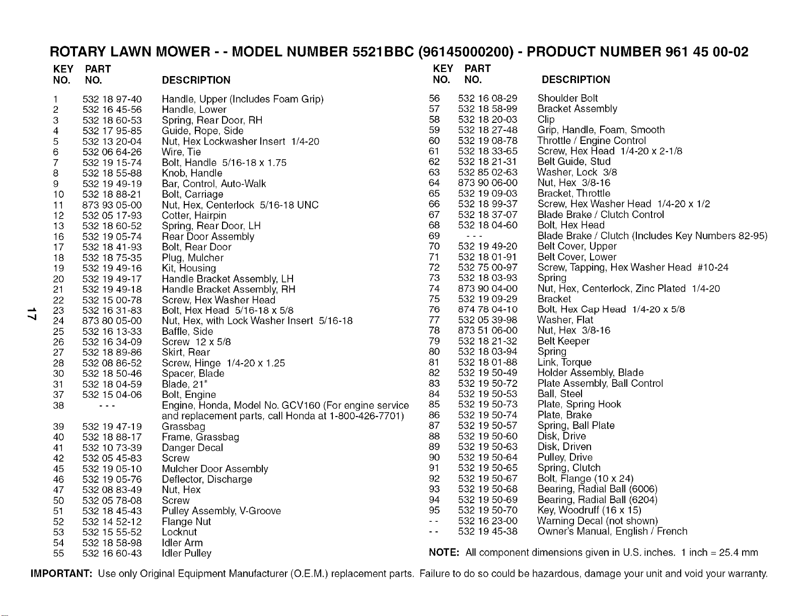
ROTARY LAWN MOWER - - MODEL NUMBER 5521BBC (96145000200) - PRODUCT NUMBER 961 45 00-02
KEY PART KEY PART
NO. NO. DESCRIPTION NO. NO. DESCRIPTION
1 532 18 97-40 Handle, Upper (Includes Foam Grip) 56 532 16 08-29
2 532 16 45-56 Handle, Lower 57 532 18 58-99
3 532 18 60-53 Spring, Rear Door, RH 58 532 18 20-03
4 532 17 95-85 Guide, Rope, Side 59 532 18 27-48
5 532 13 20-04 Nut, Hex Lockwasher Insert 1/4-20 60 532 19 08-78
6 532 06 64-26 Wire, Tie 61 532 18 33-65
7 532 19 15-74 Bolt, Handle 5/16-18 x 1.75 62 532 18 21-31
8 532 18 55-88 Knob, Handle 63 532 85 02-63
9 532 19 49-19 Bar, Control, Auto-Walk 64 873 90 06-00
10 532 18 88-21 Bolt, Carriage 65 532 19 09-03
11 873 93 05-00 Nut, Hex, Centerlock 5/16-18 UNC 66 532 18 99-37
12 532 05 17-93 Cotter, Hairpin 67 532 18 37-07
13 532 18 60-52 Spring, Rear Door, LH 68 532 18 04-60
16 532 19 05-74 Rear Door Assembly 69 - - -
17 532 18 41-93 Bolt, Rear Door 70 532 19 49-20
18 532 18 75-35 Plug, Mulcher 71 532 18 01-91
19 532 19 49-16 Kit, Housing 72 532 75 00-97
20 532 19 49-17 Handle Bracket Assembly, LH 73 532 18 03-93
21 532 19 49-18 Handle Bracket Assembly, RH 74 873 90 04-00
22 532 15 00-78 Screw, Hex Washer Head 75 532 19 09-29
23 532 1631-83 Bolt, Hex Head 5/16-18x5/8 76 8747804-10
24 873 80 05-00 Nut, Hex, with Lock Washer Insert 5/16-18 77 532 05 39-98
25 532 16 13-33 Baffle, Side 78 873 51 06-00
26 532 16 34-09 Screw 12 x 5/8 79 532 18 21-32
27 532 18 89-86 Skirt, Rear 80 532 18 03-94
28 532 08 86-52 Screw, Hinge 1/4-20 x 1.25 81 532 18 01-88
30 532 18 50-46 Spacer, Blade 82 532 19 50-49
31 532 18 04-59 Blade, 21" 83 532 19 50-72
37 532 15 04-06 Bolt, Engine 84 532 19 50-53
38 - - - Engine, Honda, Model No. GCV160 (For engine service 85 532 19 50-73
and replacement parts, call Honda at 1-800-426-7701 ) 86 532 19 50-74
39 532 19 47-19 G rassbag 87 532 19 50-57
40 532 18 88-17 Frame, Grassbag 88 532 19 50-60
41 532 10 73-39 Danger Decal 89 532 19 50-63
42 532 05 45-83 Screw 90 532 19 50-64
45 532 19 05-10 Mulcher Door Assembly 91 532 19 50-65
46 532 19 05-76 Deflector, Discharge 92 532 19 50-67
47 532 08 83-49 Nut, Hex 93 532 19 50-68
50 532 05 78-08 Screw 94 532 19 50-69
51 532 18 45-43 Pulley Assembly, V-Groove 95 532 19 50-70
52 532 14 52-12 Flange Nut - - 532 16 23-00
53 532 15 55-52 Locknut - - 532 19 45-38
54 532 18 58-98 Idler Arm
55 532 16 60-43 Idler Pulley
Shoulder Bolt
Bracket Assembly
Clip
Grip, Handle, Foam, Smooth
Throttle / Engine Control
Screw, Hex Head 1/4-20 x 2-1/8
Belt Guide, Stud
Washer, Lock 3/8
Nut, Hex 3/8-16
Bracket, Throttle
Screw, Hex Washer Head 1/4-20 x 1/2
Blade Brake / Clutch Control
Bolt, Hex Head
Blade Brake / Clutch (Includes Key Numbers 82-95)
Belt Cover, Upper
Belt Cover, Lower
Screw, Tapping, Hex Washer Head #10-24
Spring
Nut, Hex, Centerlock, Zinc Plated 1/4-20
Bracket
Bolt, Hex Cap Head 1/4-20 x 5/8
Washer, Flat
Nut, Hex 3/8-16
Belt Keeper
Spring
Link, Torque
Holder Assembly, Blade
Plate Assembly, Ball Control
Ball, Steel
Plate, Spring Hook
Plate, Brake
Spring, Ball Plate
Disk, Drive
Disk, Driven
Pulley, Drive
Spring, Clutch
Bolt, Flange (10 x 24)
Bearing, Radial Ball (6006)
Bearing, Radial Ball (6204)
Key, Woodruff (16 x 15)
Warning Decal (not shown)
Owner's Manual, English / French
NOTE: All component dimensions given in U.S. inches. 1 inch = 25.4 mm
IMPORTANT: Use only Original Equipment Manufacturer (O.E.M.) replacement parts. Failure to do so could be hazardous, damage your unit and void your warranty.
Loading ...
Loading ...
Loading ...