MT03N
OWNER’S MANUAL
B5W-F8199-12
MOTORCYCLE
Read this manual carefully before oper-
ating this vehicle.
MT-03
LIT-11626-35-66
EAU10045
Operating, servicing and
maintaining a passenger vehicle or off-road vehicle can
expose you to chemicals including engine exhaust,
carbon monoxide, phthalates, and lead, which are
known to the State of California to cause cancer and
birth defects or other reproductive harm. To minimize
exposure, avoid breathing exhaust, do not idle the
engine except as necessary, service your vehicle in a
well-ventilated area and wear gloves or wash your
hands frequently when servicing your vehicle. For more
information go to
www.P65Warnings.ca.gov/passenger-vehicle
Read this manual carefully before operating the vehicle. This manual
should stay with the vehicle if it is sold.
Introduction
EAU10084
Congratulations on your purchase of the Yamaha MT03N. This model is the result
of Yamaha’s vast experience in the production of fine sporting, touring, and pace-
setting racing machines. It represents the high degree of craftsmanship and reli-
ability that have made Yamaha a leader in these fields.
This manual will give you an understanding of the operation, inspection, and basic
maintenance of this motorcycle. If you have any questions concerning the opera-
tion or maintenance of your motorcycle, please consult a Yamaha dealer.
The design and manufacture of this Yamaha motorcycle fully comply with the
emissions standards for clean air applicable at the date of manufacture. Yamaha
has met these standards without reducing the performance or economy of oper-
ation of the motorcycle. To maintain these high standards, it is important that you
and your Yamaha dealer pay close attention to the recommended maintenance
schedules and operating instructions contained within this manual.
Yamaha continually seeks advancements in product design and quality. There-
fore, while this manual contains the most current product information available at
the time of printing, there may be minor discrepancies between your motorcycle
and this manual. If there is any question concerning this manual, please consult a
Yamaha dealer.
WARNING
EWA10012
Please read this manual and the “YOU AND YOUR MOTORCYCLE: RIDING
TIPS” booklet carefully before operating this motorcycle. Do not attempt to
operate this motorcycle until you have attained adequate knowledge of its
controls and operating features. Regular inspections and careful mainte-
nance, along with good operating techniques, will help ensure that you safe-
ly enjoy the capabilities and reliability of this motorcycle.
Important manual information
EAU63350
Particularly important information is distinguished in this manual by the following
notations:
*Product and specifications are subject to change without notice.
EAUN0770
This is the safety alert symbol. It is used to
alert you to potential personal injury haz-
ards. Obey all safety messages that follow
this symbol to avoid possible injury or death.
A WARNING indicates a hazardous situation
which, if not avoided, could result in death or
serious injury.
A NOTICE indicates special precautions that
must be taken to avoid damage to the vehi-
cle or other property.
A TIP provides key information to make proce-
dures easier or clearer.
MT03N
OWNER’S MANUAL
©2022 by Yamaha Motor Corporation,
U.S.A.
1st edition, October 2021
All rights reserved.
Any reprinting or unauthorized use
without the written permission of
Yamaha Motor Corporation, U.S.A.
is expressly prohibited.
Printed in Indonesia.
P/N LIT-11626-35-66
WARNING
NOTICE
TIP

Table of contents
Location of important labels............1-1
Safety information ............................2-1
Description ........................................3-1
Left view ..........................................3-1
Right view........................................3-2
Controls and instruments................3-3
Instrument and control functions....4-1
Main switch/steering lock ...............4-1
Indicator lights and
warning lights...............................4-2
Multi-function meter unit .................4-4
Handlebar switches.......................4-10
Clutch lever ...................................4-12
Shift pedal .....................................4-12
Brake lever ....................................4-13
Brake pedal ...................................4-13
ABS ...............................................4-14
Fuel tank cap.................................4-15
Fuel................................................4-15
Fuel tank overflow hose ................4-17
Catalytic converter ........................4-17
Seats .............................................4-18
Helmet holders ..............................4-19
Storage compartment ...................4-20
Adjusting the shock absorber
assembly....................................4-21
Luggage strap holders ..................4-22
Sidestand ......................................4-22
Ignition circuit cut-off system........4-23
For your safety – pre-operation
checks ...............................................5-1
Operation and important riding
points .................................................6-1
Engine break-in ...............................6-1
Starting the engine ..........................6-2
Shifting ............................................6-3
Parking ............................................6-5
Periodic maintenance and
adjustment ........................................7-1
Tool kit.............................................7-2
Periodic maintenance chart for
the emission control system........ 7-3
General maintenance and
lubrication chart........................... 7-4
Checking the spark plugs ............... 7-7
Canister...........................................7-8
Engine oil and oil filter cartridge ..... 7-8
Why Yamalube.............................. 7-11
Coolant ......................................... 7-12
Replacing the air filter element
and cleaning the check hose..... 7-13
Checking the throttle
grip free play.............................. 7-15
Valve clearance.............................7-15
Tires ..............................................7-16
Cast wheels .................................. 7-18
Adjusting the clutch lever
free play..................................... 7-18
Checking the brake lever
free play..................................... 7-19
Brake light switches...................... 7-20
Checking the front and rear
brake pads................................. 7-20
Checking the brake fluid level....... 7-21
Changing the brake fluid...............7-22
Drive chain slack........................... 7-23
Cleaning and lubricating the
drive chain .................................7-24
Checking and lubricating
the cables.................................. 7-25
Checking and lubricating the
throttle grip and cable ...............7-25
Checking and lubricating the
brake and shift pedals...............7-26
Checking and lubricating the
brake and clutch levers .............7-26
Checking and lubricating the
sidestand ................................... 7-27
Lubricating the swingarm
pivots......................................... 7-27
Checking the front fork ................. 7-28
Checking the steering ...................7-28
Checking the wheel bearings ....... 7-29
Battery ..........................................7-29
Replacing the fuses ...................... 7-31
Vehicle lights.................................7-33

Table of contents
Replacing the license plate
light bulb ................................... 7-33
Supporting the motorcycle........... 7-34
Troubleshooting............................ 7-35
Troubleshooting chart .................. 7-36
Motorcycle care and storage.......... 8-1
Matte color caution ........................ 8-1
Care ................................................ 8-1
Storage........................................... 8-4
Specifications................................... 9-1
Consumer information................... 10-1
Identification numbers.................. 10-1
Vehicle data recording.................. 10-3
Reporting safety defects .............. 10-4
Motorcycle noise regulation ......... 10-5
Maintenance record ..................... 10-6
YAMAHA MOTOR CORPORATION,
U.S.A. 2020 AND LATER MODEL
STREET & DUAL-PURPOSE
MOTORCYCLE LIMITED
WARRANTY .............................. 10-7
YAMAHA EXTENDED SERVICE
(Y.E.S.) ...................................... 10-9
Index................................................ 11-1
Location of important labels
1-1
1
EAU63360
Read and understand all of the labels on your vehicle. They contain important in-
formation for safe and proper operation of your vehicle. Never remove any labels
from your vehicle. If a label becomes difficult to read or comes off, a replacement
label is available from your Yamaha dealer.
12
3
Location of important labels
1-2
1
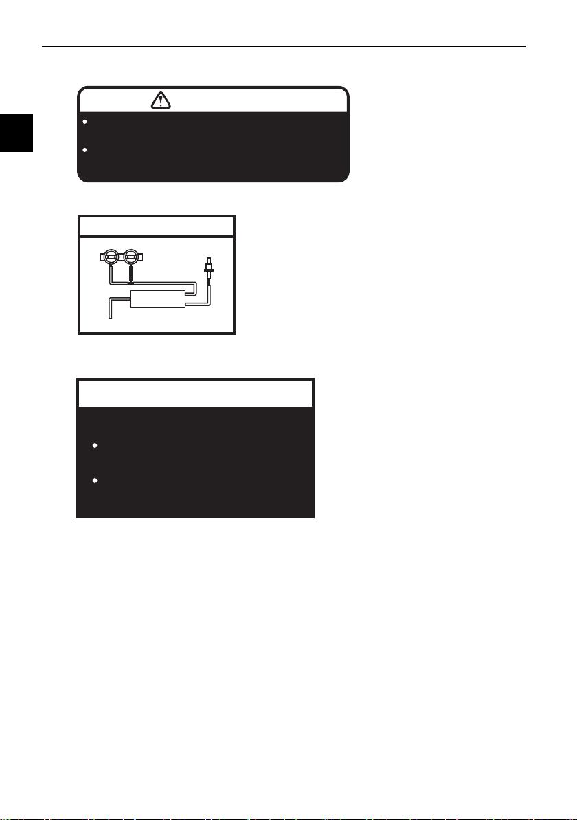
BEFORE YOU OPERATE THIS VEHICLE, READ
THE OWNER’S MANUAL AND ALL LABELS.
WARNING
TIRE INFORMATION
ALWAYS WEAR AN APPROVED MOTORCYCLE
HELMET, eye protection, and protective clothing.
1TP-2118K-A1
2MS-F1668-20
Cold tire normal pressure should be set
as follows.
FRONT : 200kPa, (2.00 kgf/cm
2
), 29 psi
REAR : 250kPa, (2.50 kgf/cm
2
), 36 psi
Up to 90kg (198lbs) load
FRONT : 200kPa, (2.00 kgf/cm
2
), 29 psi
REAR : 250kPa, (2.50 kgf/cm
2
), 36 psi
90kg (198lbs)-maximun load
EMISSION HOSE ROUTING
THROTTLE BODY FROM
FUEL TANK
ROLL OVER
VALVE
4B5-21686-00
CANISTER
TO ATMOSPHERE
1
2
3

2-1
2
Safety information
EAU1028C
Be a Responsible Owner
As the vehicle’s owner, you are re-
sponsible for the safe and proper oper-
ation of your motorcycle.
Motorcycles are single-track vehicles.
Their safe use and operation are de-
pendent upon the use of proper riding
techniques as well as the expertise of
the operator. Every operator should
know the following requirements be-
fore riding this motorcycle.
He or she should:
z Obtain thorough instructions from
a competent source on all aspects
of motorcycle operation.
z Observe the warnings and mainte-
nance requirements in this Own-
er’s Manual.
z Obtain qualified training in safe
and proper riding techniques.
z Obtain professional technical ser-
vice as indicated in this Owner’s
Manual and/or when made neces-
sary by mechanical conditions.
z Never operate a motorcycle with-
out proper training or instruction.
Take a training course. Beginners
should receive training from a cer-
tified instructor. Contact an autho-
rized motorcycle dealer to find out
about the training courses nearest
you.
Safe Riding
Perform the pre-operation checks
each time you use the vehicle to make
sure it is in safe operating condition.
Failure to inspect or maintain the vehi-
cle properly increases the possibility of
an accident or equipment damage.
See page 5-1 for a list of pre-operation
checks.
z This motorcycle is designed to
carry the operator and a passen-
ger.
z The failure of motorists to detect
and recognize motorcycles in traf-
fic is the predominating cause of
automobile/motorcycle accidents.
Many accidents have been
caused by an automobile driver
who did not see the motorcycle.
Making yourself conspicuous ap-
pears to be very effective in reduc-
ing the chance of this type of
accident.
Therefore:
• Wear a brightly colored jacket.
• Use extra caution when you are
approaching and passing
through intersections, since in-
tersections are the most likely
places for motorcycle accidents
to occur.
• Ride where other motorists can
see you. Avoid riding in another
motorist’s blind spot.
• Never maintain a motorcycle
without proper knowledge.
Contact an authorized motorcy-
cle dealer to inform you on ba-
sic motorcycle maintenance.
Certain maintenance can only
be carried out by certified staff.

Safety information
2-2
2
z Many accidents involve inexperi-
enced operators. In fact, many op-
erators who have been involved in
accidents do not even have a cur-
rent motorcycle license.
• Make sure that you are qualified
and that you only lend your mo-
torcycle to other qualified oper-
ators.
• Know your skills and limits.
Staying within your limits may
help you to avoid an accident.
• We recommend that you prac-
tice riding your motorcycle
where there is no traffic until you
have become thoroughly famil-
iar with the motorcycle and all of
its controls.
z Many accidents have been
caused by error of the motorcycle
operator. A typical error made by
the operator is veering wide on a
turn due to excessive speed or un-
dercornering (insufficient lean an-
gle for the speed).
• Always obey the speed limit and
never travel faster than warrant-
ed by road and traffic condi-
tions.
• Always signal before turning or
changing lanes. Make sure that
other motorists can see you.
z The posture of the operator and
passenger is important for proper
control.
• The operator should keep both
hands on the handlebar and
both feet on the operator foot-
rests during operation to main-
tain control of the motorcycle.
• The passenger should always
hold onto the operator, the seat
strap or grab bar, if equipped,
with both hands and keep both
feet on the passenger footrests.
Never carry a passenger unless
he or she can firmly place both
feet on the passenger footrests.
z Never ride under the influence of
alcohol or other drugs.
z This motorcycle is designed for
on-road use only. It is not suitable
for off-road use.
Protective Apparel
The majority of fatalities from motorcy-
cle accidents are the result of head in-
juries. The use of a safety helmet is the
single most critical factor in the pre-
vention or reduction of head injuries.
z Always wear an approved helmet.
z Wear a face shield or goggles.
Wind in your unprotected eyes
could contribute to an impairment
of vision that could delay seeing a
hazard.
z The use of a jacket, heavy boots,
trousers, gloves, etc., is effective
in preventing or reducing abra-
sions or lacerations.
z Never wear loose-fitting clothes,
otherwise they could catch on the
control levers, footrests, or wheels
and cause injury or an accident.
z Always wear protective clothing
that covers your legs, ankles, and
feet. The engine or exhaust sys-
tem become very hot during or af-
ter operation and can cause
burns.
z A passenger should also observe
the above precautions.
Safety information
2-3
2
Avoid Carbon Monoxide Poisoning
All engine exhaust contains carbon
monoxide, a deadly gas. Breathing
carbon monoxide can cause head-
aches, dizziness, drowsiness, nausea,
confusion, and eventually death.
Carbon Monoxide is a colorless, odor-
less, tasteless gas which may be pres-
ent even if you do not see or smell any
engine exhaust. Deadly levels of car-
bon monoxide can collect rapidly and
you can quickly be overcome and un-
able to save yourself. Also, deadly lev-
els of carbon monoxide can linger for
hours or days in enclosed or poorly
ventilated areas. If you experience any
symptoms of carbon monoxide poi-
soning, leave the area immediately, get
fresh air, and SEEK MEDICAL TREAT-
MENT.
z Do not run engine indoors. Even if
you try to ventilate engine exhaust
with fans or open windows and
doors, carbon monoxide can rap-
idly reach dangerous levels.
z Do not run engine in poorly venti-
lated or partially enclosed areas
such as barns, garages, or car-
ports.
z Do not run engine outdoors where
engine exhaust can be drawn into
a building through openings such
as windows and doors.
Loading
Adding accessories or cargo to your
motorcycle can adversely affect stabil-
ity and handling if the weight distribu-
tion of the motorcycle is changed. To
avoid the possibility of an accident, use
extreme caution when adding cargo or
accessories to your motorcycle. Use
extra care when riding a motorcycle
that has added cargo or accessories.
Here, along with the information about
accessories below, are some general
guidelines to follow if loading cargo to
your motorcycle:
The total weight of the operator, pas-
senger, accessories and cargo must
not exceed the maximum load limit.
Operation of an overloaded vehicle
could cause an accident.
When loading within this weight limit,
keep the following in mind:
z Cargo and accessory weight
should be kept as low and close to
the motorcycle as possible. Se-
curely pack your heaviest items as
close to the center of the vehicle
as possible and make sure to dis-
tribute the weight as evenly as
possible on both sides of the mo-
torcycle to minimize imbalance or
instability.
z Shifting weights can create a sud-
den imbalance. Make sure that
accessories and cargo are se-
curely attached to the motorcycle
before riding. Check accessory
mounts and cargo restraints fre-
quently.
• Properly adjust the suspension
for your load (suspension-ad-
justable models only), and
check the condition and pres-
sure of your tires.
• Never attach any large or heavy
items to the handlebar, front
fork, or front fender. These
items, including such cargo as
Maximum load:
160 kg (353 lb)

Safety information
2-4
2
sleeping bags, duffel bags, or
tents, can create unstable han-
dling or a slow steering re-
sponse.
z This vehicle is not designed to
pull a trailer or to be attached to
a sidecar.
Genuine Yamaha Accessories
Choosing accessories for your vehicle
is an important decision. Genuine
Yamaha accessories, which are avail-
able only from a Yamaha dealer, have
been designed, tested, and approved
by Yamaha for use on your vehicle.
Many companies with no connection
to Yamaha manufacture parts and ac-
cessories or offer other modifications
for Yamaha vehicles. Yamaha is not in
a position to test the products that
these aftermarket companies produce.
Therefore, Yamaha can neither en-
dorse nor recommend the use of ac-
cessories not sold by Yamaha or
modifications not specifically recom-
mended by Yamaha, even if sold and
installed by a Yamaha dealer.
Aftermarket Parts, Accessories, and
Modifications
While you may find aftermarket prod-
ucts similar in design and quality to
genuine Yamaha accessories, recog-
nize that some aftermarket accesso-
ries or modifications are not suitable
because of potential safety hazards to
you or others. Installing aftermarket
products or having other modifications
performed to your vehicle that change
any of the vehicle’s design or operation
characteristics can put you and others
at greater risk of serious injury or
death. You are responsible for injuries
related to changes in the vehicle.
Keep the following guidelines in mind,
as well as those provided under “Load-
ing” when mounting accessories.
z Never install accessories or carry
cargo that would impair the per-
formance of your motorcycle.
Carefully inspect the accessory
before using it to make sure that it
does not in any way reduce
ground clearance or cornering
clearance, limit suspension travel,
steering travel or control opera-
tion, or obscure lights or reflec-
tors.
• Accessories fitted to the han-
dlebar or the front fork area can
create instability due to improp-
er weight distribution or aerody-
namic changes. If accessories
are added to the handlebar or
front fork area, they must be as
lightweight as possible and
should be kept to a minimum.
• Bulky or large accessories may
seriously affect the stability of
the motorcycle due to aerody-
namic effects. Wind may at-
tempt to lift the motorcycle, or
the motorcycle may become
unstable in cross winds. These
accessories may also cause in-
stability when passing or being
passed by large vehicles.
• Certain accessories can dis-
place the operator from his or
her normal riding position. This
improper position limits the
freedom of movement of the
Safety information
2-5
2
operator and may limit control
ability, therefore, such accesso-
ries are not recommended.
z Use caution when adding electri-
cal accessories. If electrical ac-
cessories exceed the capacity of
the motorcycle’s electrical sys-
tem, an electric failure could re-
sult, which could cause a
dangerous loss of lights or engine
power.
Aftermarket Tires and Rims
The tires and rims that came with your
motorcycle were designed to match
the performance capabilities and to
provide the best combination of han-
dling, braking, and comfort. Other
tires, rims, sizes, and combinations
may not be appropriate. See page 7-16
for tire specifications and for informa-
tion on servicing and replacing your
tires.
Transporting the Motorcycle
Be sure to observe following instruc-
tions before transporting the motorcy-
cle in another vehicle.
z Remove all loose items from the
motorcycle.
z Check that the fuel cock (if
equipped) is in the off position and
that there are no fuel leaks.
z Shift the transmission into gear
(for models with a manual trans-
mission).
z Secure the motorcycle with tie-
downs or suitable straps that are
attached to solid parts of the mo-
torcycle, such as the frame or up-
per front fork triple clamp (and not,
for example, to rubber-mounted
handlebars or turn signals, or
parts that could break). Choose
the location for the straps carefully
so the straps will not rub against
painted surfaces during transport.
z The suspension should be com-
pressed somewhat by the tie-
downs, if possible, so that the mo-
torcycle will not bounce exces-
sively during transport.
Description
3-1
3
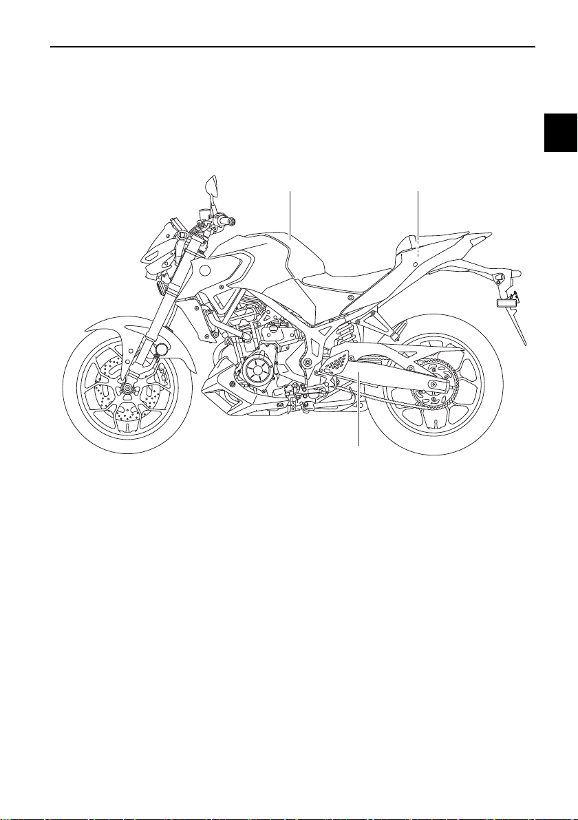
EAU63371
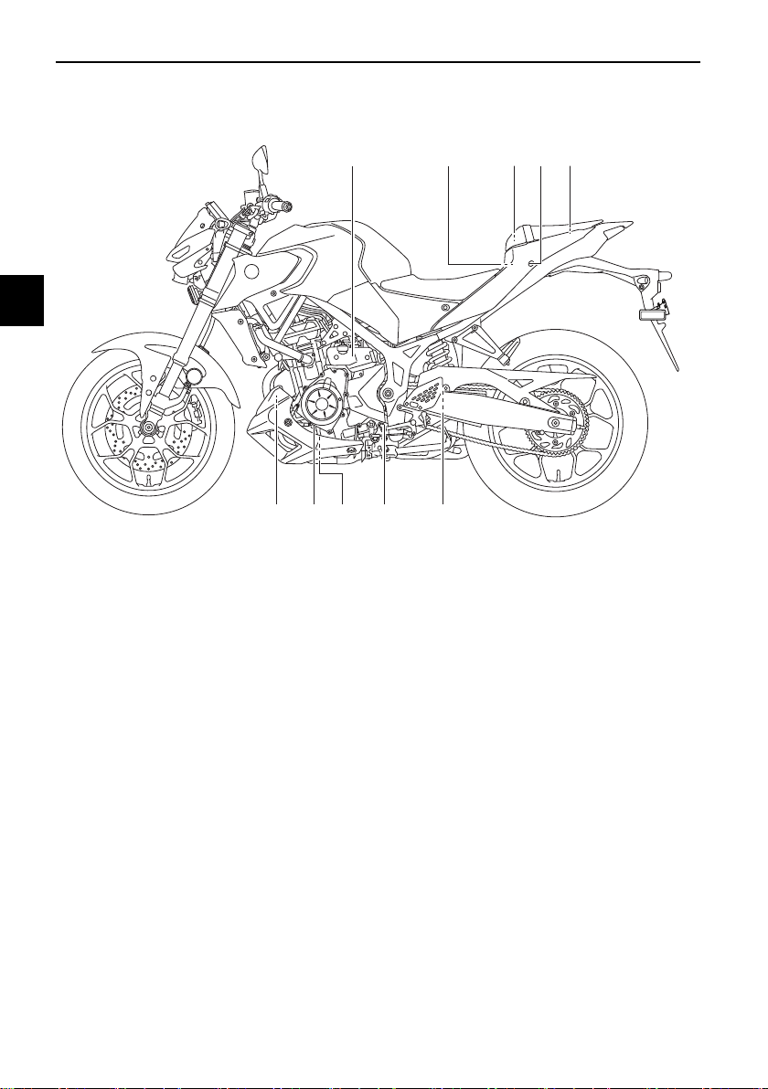
Left view
12345
9
10 8 7 6
1. Coolant reservoir (page 7-12)
2. Main fuse (page 7-31)
3. Tool kit (page 7-2)
4. Passenger seat lock (page 4-18)
5. Storage compartment (page 4-20)
6. Shock absorber assembly spring preload adjusting ring (page 4-21)
7. Shift pedal (page 4-12)
8. Engine oil drain bolt (page 7-8)
9. Engine oil filter cartridge (page 7-8)
10.Canister (page 7-8)
Description
3-2
3
EAU63391
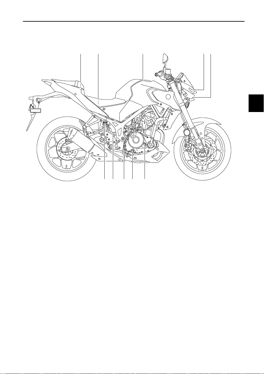
Right view
1 2
10 9 8 7 6
3 4 5
1. Fuse box (page 7-31)
2. Battery (page 7-29)
3. Fuel tank cap (page 4-15)
4. Auxiliary light
5. Headlight (page 7-33)
6. Engine oil filler cap (page 7-8)
7. Engine oil level check window (page 7-8)
8. Brake pedal (page 4-13)
9. Rear brake light switch (page 7-20)
10.Rear brake fluid reservoir (page 7-21)
Description
3-3
3
EAU63401
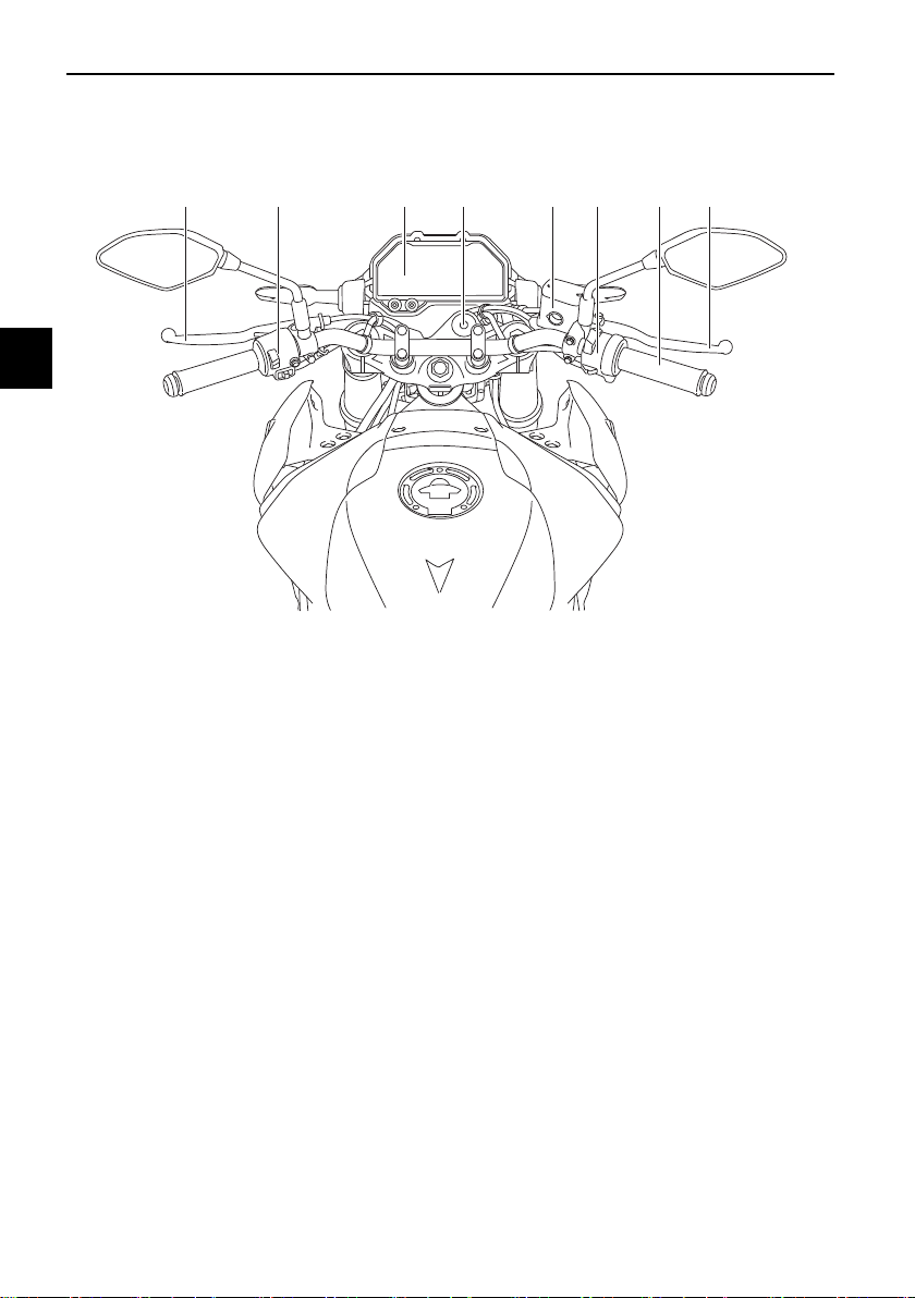
Controls and instruments
12 456783
1. Clutch lever (page 4-12)
2. Left handlebar switches (page 4-10)
3. Multi-function meter unit (page 4-4)
4. Main switch/steering lock (page 4-1)
5. Front brake fluid reservoir (page 7-21)
6. Right handlebar switches (page 4-10)
7. Throttle grip (page 7-15)
8. Brake lever (page 4-13)
Instrument and control functions
4-1
4
EAU10462
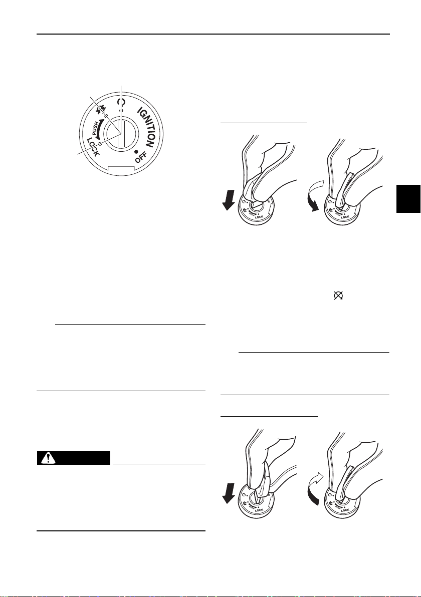
Main switch/steering lock
The main switch/steering lock controls
the ignition and lighting systems, and is
used to lock the steering. The various
positions are described below.
EAU85040
ON
All electrical circuits are supplied with
power and the vehicle lights are turned
on. The engine can be started. The key
cannot be removed.
TIP
z To prevent battery discharge, do
not leave the key in the on position
without the engine running.
z The headlight comes on automat-
ically when the engine is started.
EAU10662
OFF
All electrical systems are off. The key
can be removed.
WARNING
EWA10062
Never turn the key to “OFF” or
“LOCK” while the vehicle is moving.
Otherwise the electrical systems will
be switched off, which may result in
loss of control or an accident.
EAU60863
LOCK
The steering is locked and all electrical
systems are off. The key can be re-
moved.
To lock the steering
1. Turn the handlebars all the way to
the left.
2. With the key in the “ ” position,
push the key in and turn it to
“LOCK”.
3. Remove the key.
TIP
If the steering will not lock, try turning
the handlebars back to the right slight-
ly.
To unlock the steering
ON
OFF
LOCK
1. Push.
2. Turn.
1. Push.
2. Turn.
12
12
Instrument and control functions
4-2
4
From the “LOCK” position, push the
key and turn it to “ ”.
EAU4939H
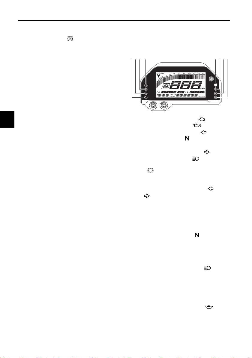
Indicator lights and warning
lights
EAU11032
Turn signal indicator lights “ ”
and “”
Each indicator light will flash when its
corresponding turn signal lights are
flashing.
EAU11061
Neutral indicator light “ ”
This indicator light comes on when the
transmission is in the neutral position.
EAU11081
High beam indicator light “ ”
This indicator light comes on when the
high beam of the headlight is switched
on.
EAU85091
Oil pressure warning light “ ”
This warning light comes on when the
engine oil pressure is low.
1. Engine trouble warning light “ ”
2. Oil pressure warning light “ ”
3. Left turn signal indicator light “ ”
4. Neutral indicator light “ ”
5. Shift timing indicator light
6. Right turn signal indicator light “ ”
7. High beam indicator light “ ”
8. Anti-lock Brake System (ABS) warning
light “ ”
8
MPH
MPG mile
123 4 5 67
ABS
Instrument and control functions
4-3
4
TIP
When the vehicle is turned on, the light
should come on and remain on until
the engine is started. Otherwise, have
a Yamaha dealer check the vehicle.
NOTICE
ECA21211
If the warning light comes on when
the engine is running, stop the en-
gine and check the oil level. If the oil
level is low, add sufficient oil of the
recommended type. If the warning
light remains on after adding oil,
stop the engine and have a Yamaha
dealer check the vehicle.
EAU85140
Engine trouble warning light “ ”
This warning light comes on or flashes
if a problem is detected in the engine.
If this occurs, have a Yamaha dealer
check the self-diagnosis system.
TIP
z When the vehicle is turned on, this
light should come on for a few
seconds and then go off. Other-
wise, have a Yamaha dealer check
the electrical circuit.
z The engine trouble warning light
will come on while the start switch
is pushed, but this does not indi-
cate a malfunction.
EAU69895
ABS warning light “ ”
This warning light comes on when the
vehicle is first turned on, and goes off
after starting riding. If the warning light
comes on while riding, the anti-lock
brake system may not work correctly.
WARNING
EWA16043
If the ABS warning light does not
turn off after reaching 10 km/h (6
mi/h), or if the warning light comes
on while riding:
z Use extra caution to avoid pos-
sible wheel lock during emer-
gency braking.
z Have a Yamaha dealer check
the vehicle as soon as possible.
EAU67434
Shift indicator light “ ”
This indicator light comes on when it is
time to shift to the next higher gear.
The engine speeds at which it comes
on or goes off can be adjusted. (See
page 4-8.)
TIP
When the vehicle is turned on, this light
should come on for a few seconds and
then go off. If the light does not come
on, or if the light remains on, have a
Yamaha dealer check the vehicle.
ABS
Instrument and control functions
4-4
4
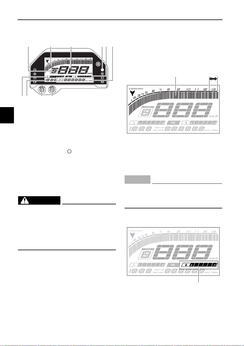
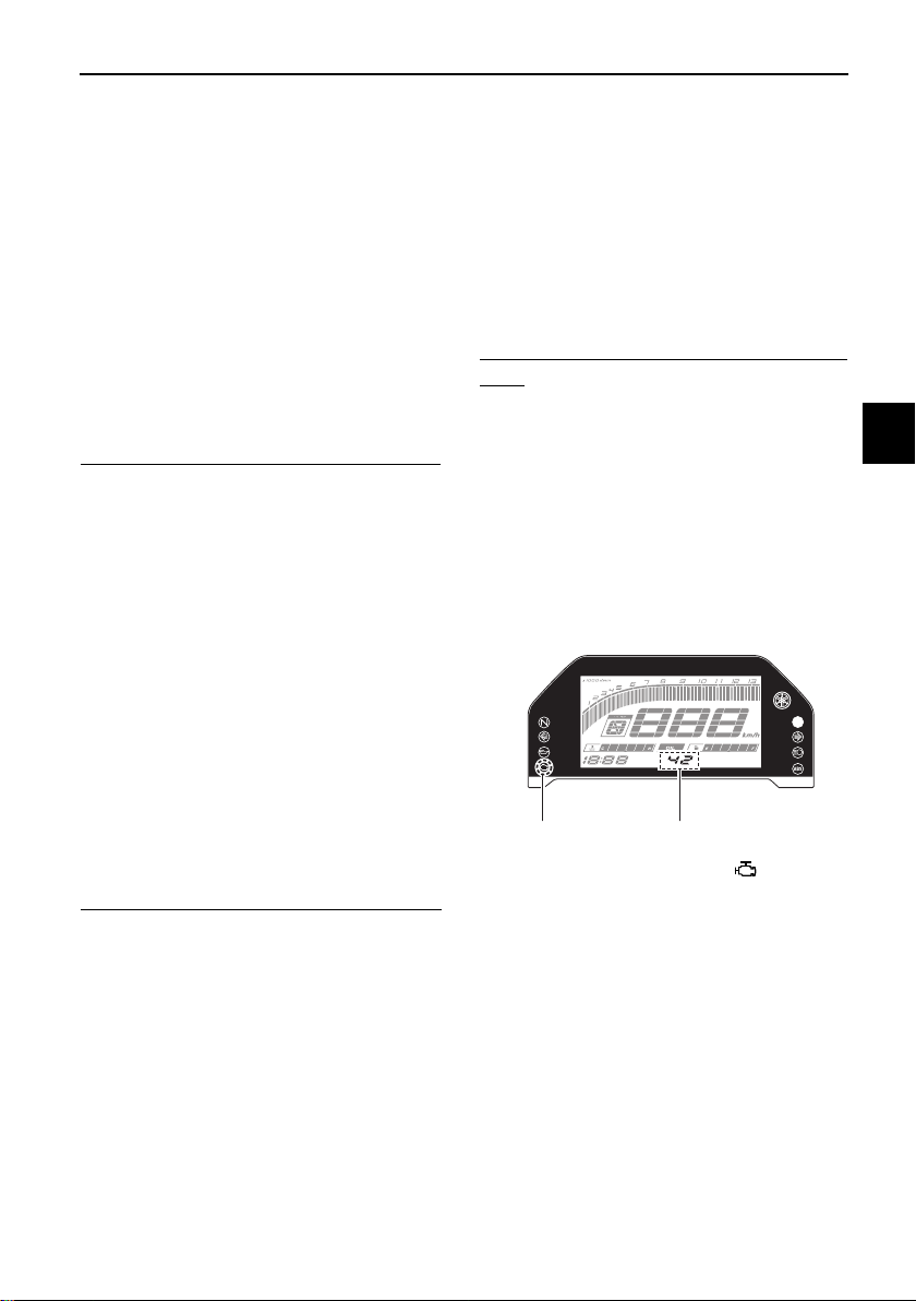
EAU87090
Multi-function meter unit
The multi-function meter unit is also
equipped with a shift indicator light
control mode.
WARNING
EWA12423
Be sure to stop the vehicle before
making any setting changes to the
multi-function meter unit. Changing
settings while riding can distract the
operator and increase the risk of an
accident.
EAU87140
Switching the display units
The display units can be switched be-
tween kilometers and miles. To switch
the display units, push the “SELECT”
button until the display units change.
EAU86831
Speedometer
The speedometer shows the vehicle’s
traveling speed.
EAU87170
Tachometer
The tachometer allows the rider to
monitor the engine speed and keep it
within the ideal power range.
NOTICE
ECA10032
Do not operate the engine in the ta-
chometer red zone.
Red zone: 12500 r/min and above
EAU86841
Fuel meter
The fuel meter indicates the amount of
fuel in the fuel tank. The display seg-
ments of the fuel meter disappear from
1. “RESET” button
2. “SELECT” button
3. Clock
4. Coolant temperature meter
5. Transmission gear display
6. Tachometer
7. Speedometer
8. Shift indicator light “ ”
9. Fuel meter
10.Multi-function display
MPH
MPG mile
3214
58910
6 7
1. Tachometer
2. Tachometer red zone
1. Fuel meter
MPH
MPG mile
1 2
MPH
MPG mile
1
Instrument and control functions
4-5
4
“F” (full) towards “E” (empty) as the fuel
level decreases. When approximately
3.0 L (0.79 US gal, 0.66 Imp.gal) of fuel
remains, the last segment starts flash-
ing. Refuel as soon as possible.
TIP
If a problem is detected in the electrical
circuit, the fuel level segments will flash
repeatedly. If this occurs, have a
Yamaha dealer check the vehicle.
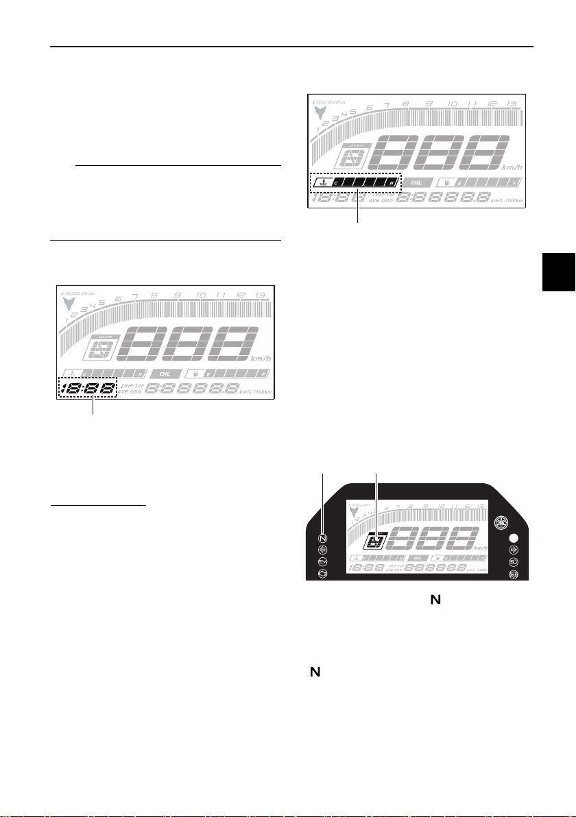
EAU87290
Clock
The clock uses a 12-hour time system.
To set the clock
1. Push both the “SELECT” button
and “RESET” button until the hour
digits start flashing.
2. Use the “RESET” button to set the
hours.
3. Push the “SELECT” button and
the minute digits start flashing.
4. Use the “RESET” button to set the
minutes.
5. Push the “SELECT” button to con-
firm the settings.
EAU87350
Coolant temperature meter
This meter shows the temperature of
the coolant, and thereby the condition
of the engine. The segments come on
from “C” (cold) to “H” (hot) as the en-
gine temperature increases. If the hot
segment flashes, stop the engine as
soon as possible, and let the engine
cool. (See page 7-37.)
EAU87400
Transmission gear display
This display shows the selected gear.
The neutral position is indicated by
“ ” and by the neutral indicator light.
1. Clock
MPH
MPG mile
1
1. Coolant temperature meter
1. Neutral indicator light “ ”
2. Transmission gear display
MPH
MPG mile
1
MPH
MPG mile
1
2
Instrument and control functions
4-6
4
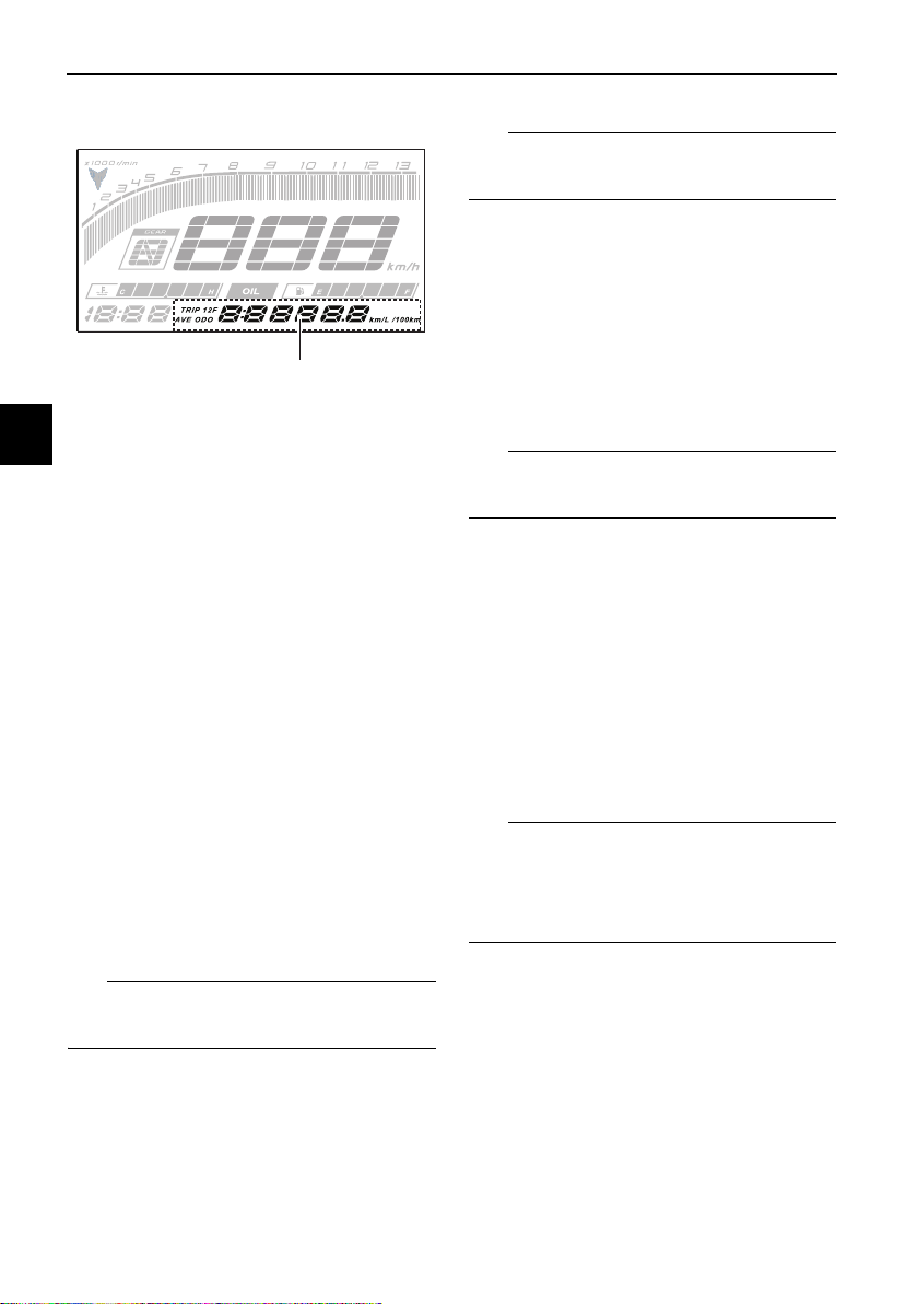
EAU87580
Multi-function display
The multi-function display is equipped
with the following:
z an odometer (ODO)
z two tripmeters (TRIP 1 and TRIP 2)
z a fuel reserve tripmeter (TRIP F)
z an oil change tripmeter (OIL TRIP)
z an oil change indicator
z an instantaneous fuel consump-
tion display (km/L, L/100 km, or
MPG)
z an average fuel consumption dis-
play (AVE_ _._ km/L, AVE_ _._
L/100 km, or AVE_ _._ MPG)
Push the “SELECT” button to change
the display in the following order:
ODO → TRIP 1 → TRIP 2 → TRIP F →
km/L, L/100 km or MPG → AVE_ _._
km/L, AVE_ _._ L/100 km or AVE_ _._
MPG → OIL TRIP → ODO
TIP
The fuel reserve tripmeter appears only
when you are low on fuel.
EAU86890
Odometer
The odometer shows the total distance
traveled by the vehicle.
TIP
The odometer will lock at 999999 and
cannot be reset.
EAU88050
Tripmeters
The tripmeters show the distance trav-
eled since they were last reset.
To reset a tripmeter, change the dis-
play to the tripmeter you want to reset,
and then push the “RESET” button un-
til it is reset.
TIP
The tripmeters will reset and continue
counting after 9999.9 is reached.
EAU87600
Fuel reserve tripmeter
If the last segment of the fuel meter
starts flashing, the display automati-
cally changes to the fuel reserve trip-
meter “TRIP F” and starts counting the
distance traveled from that point.
To reset the fuel reserve tripmeter,
push the “RESET” button until it is re-
set.
TIP
If you do not reset the fuel reserve trip-
meter manually, it will reset automati-
cally and disappear from the display
after refueling and traveling 5 km (3 mi).
1. Multi-function display
MPH
MPG mile
1
Instrument and control functions
4-7
4
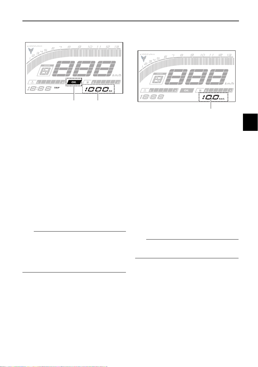
EAU88731
Oil change tripmeter
This tripmeter shows the distance trav-
eled since the last engine oil change.
The oil change indicator “OIL” will flash
at the initial 1000 km, and then at every
5000 km thereafter.
To reset the oil change tripmeter and
oil change indicator, select the oil
change tripmeter, and then push the
“RESET” button until “OIL” and the
tripmeter start flashing. While “OIL”
and the tripmeter are flashing, push the
“RESET” button until the tripmeter is
reset.
TIP
When the engine oil has been
changed, the oil change tripmeter and
the oil change indicator must be reset.
Otherwise, the oil change indicator will
not come on at the correct time.
EAU87771
Instantaneous fuel consumption
display
This display shows the fuel consump-
tion under the current riding condi-
tions. It can be set to either “km/L” or
“L/100 km”, or “MPG” when using
miles. To switch the fuel consumption
measurement units, push the “SE-
LECT” button until the measurement
units change.
z “km/L”: the distance that can be
traveled on 1.0 L of fuel.
z “L/100 km”: the amount of fuel
necessary to travel 100 km.
z “MPG”: the distance that can be
traveled on 1.0 Imp.gal of fuel.
TIP
When traveling under 10 km/h (6 mi/h),
“_ _._” is displayed.
1. Oil change indicator “OIL”
2. Oil change tripmeter
MPH
21
1. Instantaneous fuel consumption display
MPH
1
Instrument and control functions
4-8
4
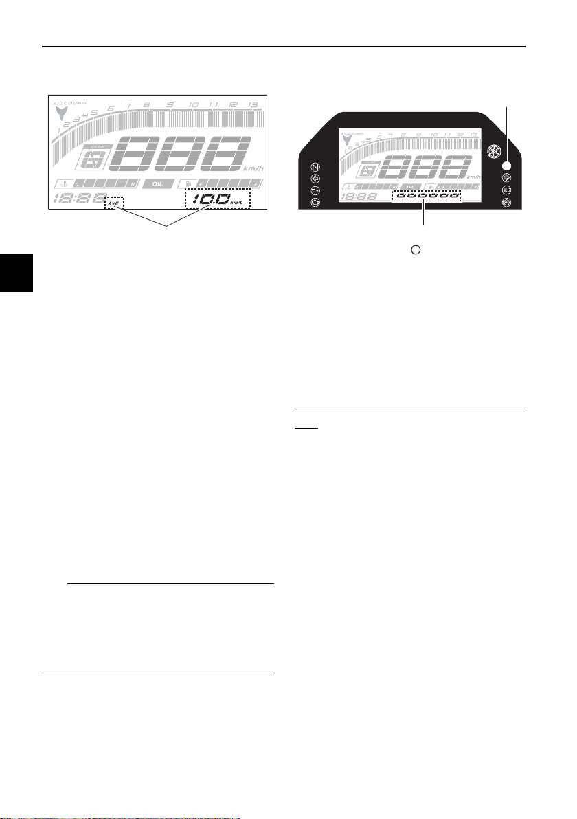
EAU87860
Average fuel consumption display
This display shows the average fuel
consumption since it was last reset.
The average fuel consumption display
can be set to either “AVE_ _._ km/L” or
“AVE_ _._ L/100 km”, or “AVE_ _._
MPG” when using miles. To switch the
fuel consumption measurement units,
push the “SELECT” button until the
measurement units change.
z “AVE_ _._ km/L”: the average dis-
tance that can be traveled on 1.0 L
of fuel.
z “AVE_ _._ L/100 km”: the average
amount of fuel necessary to travel
100 km.
z “AVE_ _._ MPG”: the average dis-
tance that can be traveled on 1.0
Imp.gal of fuel.
TIP
z To reset the display, push the
“RESET” button until it resets.
z After resetting, “_ _._” is shown
until the vehicle has traveled some
distance.
EAU87960
Shift indicator light control mode
This mode cycles through 4 control
functions in the order listed below.
z Shift indicator light on / flash / off
z Shift indicator light on r/min
z Shift indicator light off r/min
z Shift indicator light brightness
To set the shift indicator light on / flash
/ off
1. Turn the vehicle off.
2. Push and hold the “SELECT” but-
ton.
3. Turn the vehicle on, and then re-
lease the “SELECT” button after 5
seconds.
4. Push the “RESET” button to select
one of the following flashing pat-
tern settings:
z On setting: the shift indicator
light will come on when the
set engine speed is reached.
This setting is selected when
the shift indicator light stays
on.
z Flash setting: the shift indica-
tor light will flash when the set
engine speed is reached. This
1. Average fuel consumption display
MPH
1
1. Shift indicator light “ ”
2. Brightness level display
MPH
1
2
Instrument and control functions
4-9
4
setting is selected when the
shift indicator light flashes 4
times per second.
z Off setting: the shift indicator
light is deactivated. This set-
ting is selected when the shift
indicator light flashes once
every 2 seconds.
5. Push the “SELECT” button to con-
firm the setting. The control mode
changes to the shift indicator light
on r/min setting function.
To set the shift indicator light on r/min
The shift indicator light can be set be-
tween 7000 r/min and 13500 r/min.
From 7000 r/min to 12000 r/min, the in-
dicator light can be set in increments of
500 r/min. From 12000 r/min to 13500
r/min, the indicator light can be set in
increments of 200 r/min.
1. Push the “RESET” button to select
the desired engine speed for acti-
vating the shift indicator light.
2. Push the “SELECT” button to con-
firm the selected engine speed.
The control mode changes to the
shift indicator light off r/min setting
function.
To set the shift indicator light off r/min
The shift indicator light can be set be-
tween 7000 r/min and 13500 r/min.
From 7000 r/min to 12000 r/min, the in-
dicator light can be set in increments of
500 r/min. From 12000 r/min to 13500
r/min, the indicator light can be set in
increments of 200 r/min.
Be sure to set the off r/min to a higher
engine speed than the on r/min setting,
otherwise the shift indicator light will
not come on.
1. Push the “RESET” button to select
the desired engine speed for de-
activating the shift indicator light.
2. Push the “SELECT” button to con-
firm the selected engine speed.
The control mode changes to the
shift indicator light brightness set-
ting function.
To adjust the shift indicator light bright-
ness
1. Push the “RESET” button to select
the desired shift indicator light
brightness level.
2. Push the “SELECT” button to con-
firm the selected brightness level
and exit the control mode.
EAU88000
Self-diagnosis device
This model is equipped with a self-di-
agnosis device for various electrical
circuits. If a problem is detected in any
of those circuits, the engine trouble
warning light will come on and the dis-
play will indicate an error code.
1. Engine trouble warning light “ ”
2. Error code display
MPH
12
Instrument and control functions
4-10
4
NOTICE
ECA11591
If the display indicates an error
code, the vehicle should be checked
as soon as possible in order to avoid
engine damage.
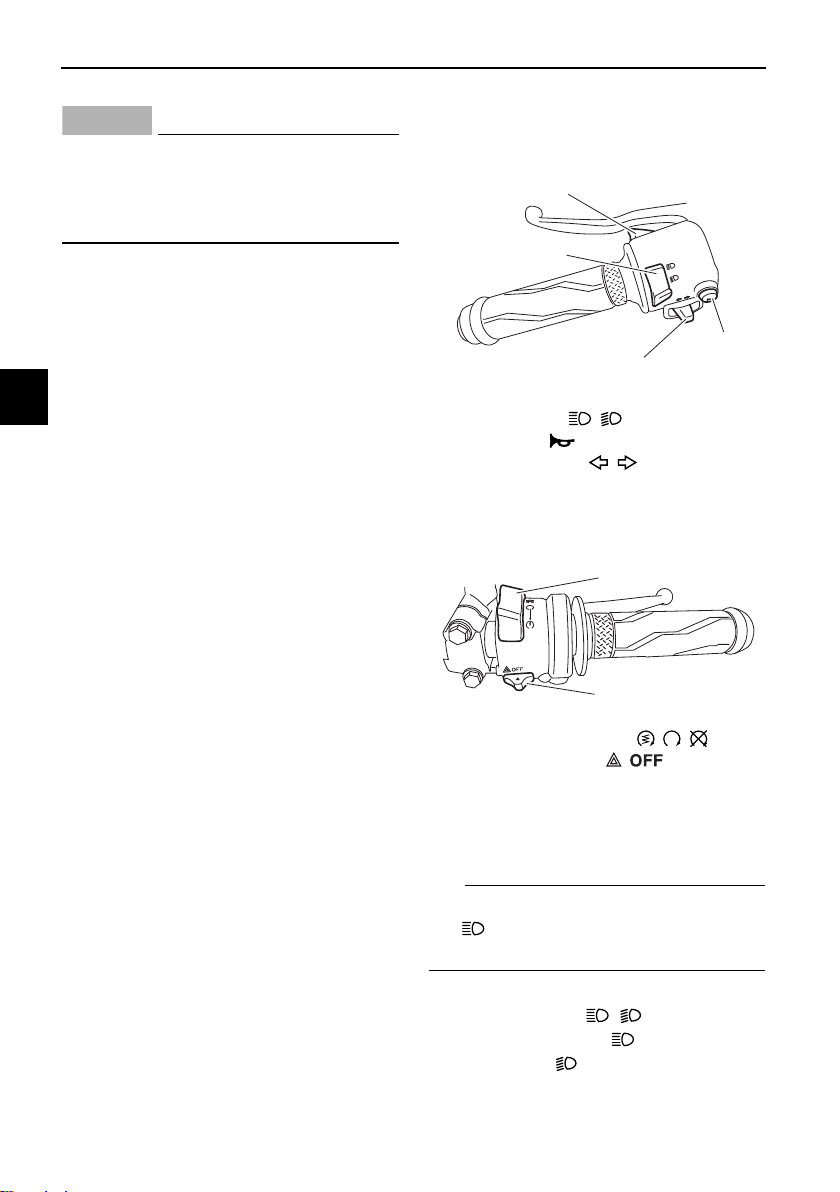
EAU1234M
Handlebar switches
Left
Right
EAU12362
Pass switch “PASS”
Press this switch to flash the headlight.
TIP
When the dimmer switch is set
to “ ”, the passing switch has no ef-
fect.
EAU12402
Dimmer switch “ / ”
Set this switch to “ ” for the high
beam and to “ ” for the low beam.
1. Pass switch “PASS”
2. Dimmer switch “ / ”
3. Horn switch “ ”
4. Turn signal switch “ / ”
1. Start/Engine stop switch “ / / ”
2. Hazard lights switch “ ”
1
2
3
4
1
2
/
Instrument and control functions
4-11
4
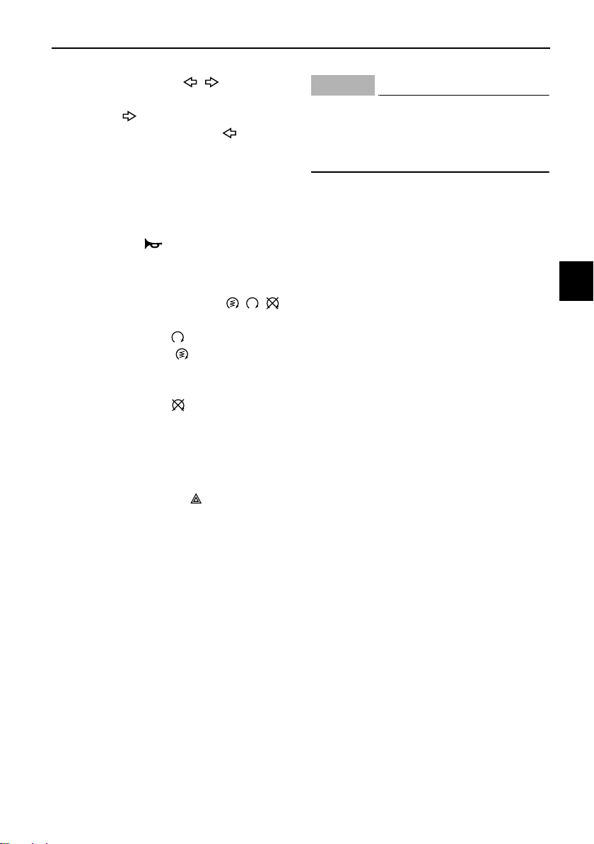
EAU12461
Turn signal switch “ / ”
To signal a right-hand turn, push this
switch to “ ”. To signal a left-hand
turn, push this switch to “ ”. When
released, the switch returns to the cen-
ter position. To cancel the turn signal
lights, push the switch in after it has re-
turned to the center position.
EAU12501
Horn switch “ ”
Press this switch to sound the horn.
EAU68270
Start/Engine stop switch “ / / ”
To crank the engine with the starter,
set this switch to “ ”, and then slide
the switch toward “ ”. See page 6-2
for starting instructions prior to starting
the engine.
Set this switch to “ ” to stop the en-
gine in case of an emergency, such as
when the vehicle overturns or when the
throttle cable is stuck.
EAU88272
Hazard switch “OFF/ ”
Use this switch to turn on the hazard
lights (simultaneous flashing of all turn
signal lights). The hazard lights are
used in case of an emergency or to
warn other drivers when your vehicle is
stopped where it might be a traffic haz-
ard.
The hazard lights can be turned on or
off only when the key is in the “ON” po-
sition. You can turn the main switch to
the “OFF” or “LOCK” position, and the
hazard lights will continue to flash. To
turn off the hazard lights, turn the main
switch to the “ON” position and oper-
ate the hazard switch again.
NOTICE
ECA10062
Do not use the hazard lights for an
extended length of time with the en-
gine not running, otherwise the bat-
tery may discharge.
Instrument and control functions
4-12
4
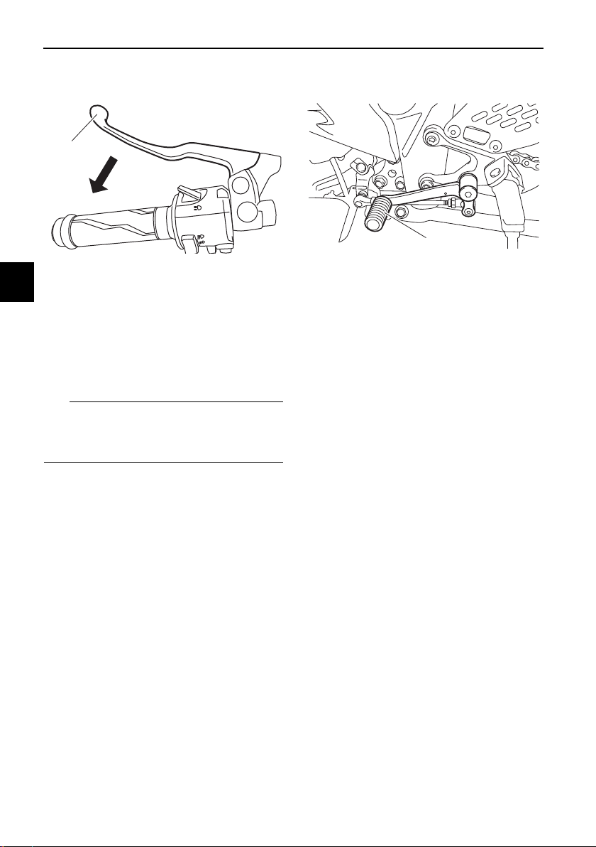
EAU12823
Clutch lever
To disengage the drivetrain from the
engine, such as when shifting gears,
pull the clutch lever toward to the han-
dlebar. Release the lever to engage the
clutch and transmit power to the rear
wheel.
TIP
The lever should be pulled rapidly and
released slowly for smooth shifting.
(See page 6-3.)
EAU12876
Shift pedal
The shift pedal is located on the left
side of the motorcycle. To shift the
transmission to a higher gear, move
the shift pedal up. To shift the trans-
mission to a lower gear, move the shift
pedal down. (See page 6-3.)
1. Clutch lever
1
1. Shift pedal
1
Instrument and control functions
4-13
4
EAU12892
Brake lever
The brake lever is located on the right
side of the handlebar. To apply the
front brake, pull the lever toward the
throttle grip.
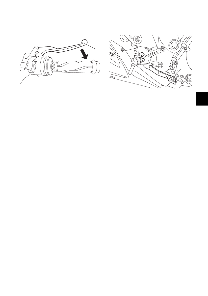
EAU12944
Brake pedal
The brake pedal is located on the right
side of the motorcycle. To apply the
rear brake, press down on the brake
pedal.
1. Brake lever
1
1. Brake pedal
1
Instrument and control functions
4-14
4
EAU63040
ABS
The Yamaha ABS (Anti-lock Brake
System) features a dual electronic con-
trol system, which acts on the front and
rear brakes independently.
Operate the brakes with ABS as you
would conventional brakes. If the ABS
is activated, a pulsating sensation may
be felt at the brake lever or brake ped-
al. In this situation, continue to apply
the brakes and let the ABS work; do
not “pump” the brakes as this will re-
duce braking effectiveness.
WARNING
EWA16051
Always keep a sufficient distance
from the vehicle ahead to match the
riding speed even with ABS.
z The ABS performs best with
long braking distances.
z On certain surfaces, such as
rough or gravel roads, the brak-
ing distance may be longer with
the ABS than without.
The ABS is monitored by an ECU,
which will revert the system to conven-
tional braking if a malfunction occurs.
TIP
z The ABS performs a self-diagno-
sis test each time the vehicle first
starts off after the key is turned to
“ON” and the vehicle has traveled
at a speed of 10 km/h (6 mi/h) or
higher. During this test, a “click-
ing” noise can be heard from the
hydraulic control unit, and if the
brake lever or brake pedal is even
slightly applied, a vibration can be
felt at the lever and pedal, but
these do not indicate a malfunc-
tion.
z This ABS has a test mode which
allows the owner to experience
the pulsation at the brake lever or
brake pedal when the ABS is op-
erating. However, special tools are
required, so please consult your
Yamaha dealer.
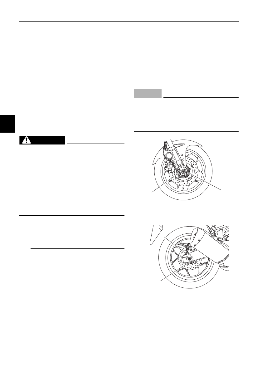
NOTICE
ECA20100
Be careful not to damage the wheel
sensor or wheel sensor rotor; other-
wise, improper performance of the
ABS will result.
1. Front wheel sensor
2. Front wheel sensor rotor
1. Rear wheel sensor
2. Rear wheel sensor rotor
1
2
1
2
Instrument and control functions
4-15
4
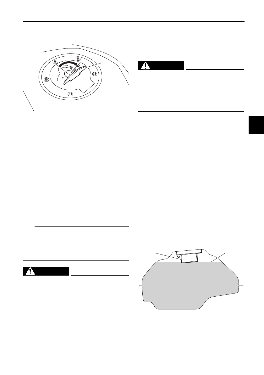
EAU13077
Fuel tank cap
To open the fuel tank cap
Open the fuel tank cap lock cover, in-
sert the key, and then turn it 1/4 turn
clockwise. The lock will be released
and the fuel tank cap can be opened.
To close the fuel tank cap
With the key still inserted, push down
the fuel tank cap. Turn the key 1/4 turn
counterclockwise, remove it, and then
close the lock cover.
TIP
The fuel tank cap cannot be closed un-
less the key is in the lock. In addition,
the key cannot be removed if the cap is
not properly closed and locked.
WARNING
EWA11092
Make sure that the fuel tank cap is
properly closed after filling fuel.
Leaking fuel is a fire hazard.
EAU13222
Fuel
Make sure there is sufficient gasoline in
the tank.
WARNING
EWA10882
Gasoline and gasoline vapors are
extremely flammable. To avoid fires
and explosions and to reduce the
risk of injury when refueling, follow
these instructions.
1. Before refueling, turn off the en-
gine and be sure that no one is sit-
ting on the vehicle. Never refuel
while smoking, or while in the vi-
cinity of sparks, open flames, or
other sources of ignition such as
the pilot lights of water heaters
and clothes dryers.
2. Do not overfill the fuel tank. When
refueling, be sure to insert the
pump nozzle into the fuel tank filler
hole. Stop filling when the fuel
reaches the bottom of the filler
tube. Because fuel expands when
it heats up, heat from the engine or
the sun can cause fuel to spill out
of the fuel tank.
1. Fuel tank cap lock cover
2. Unlock.
1
2
1. Fuel tank filler tube
2. Maximum fuel level
21

Instrument and control functions
4-16
4
3. Wipe up any spilled fuel immedi-
ately. NOTICE: Immediately
wipe off spilled fuel with a clean,
dry, soft cloth, since fuel may
deteriorate painted surfaces or
plastic parts.
[ECA10072]
4. Be sure to securely close the fuel
tank cap.
WARNING
EWA15152
Gasoline is poisonous and can
cause injury or death. Handle gaso-
line with care. Never siphon gasoline
by mouth. If you should swallow
some gasoline or inhale a lot of gas-
oline vapor, or get some gasoline in
your eyes, see your doctor immedi-
ately. If gasoline spills on your skin,
wash with soap and water. If gaso-
line spills on your clothing, change
your clothes.
EAU13315
NOTICE
ECA11401
Use only unleaded gasoline. The use
of leaded gasoline will cause severe
damage to internal engine parts,
such as the valves and piston rings,
as well as to the exhaust system.
Your Yamaha engine has been de-
signed to use regular unleaded gaso-
line with a pump octane number
[(R+M)/2] of 86 or higher, or a research
octane number of 91 or higher. If
knocking (or pinging) occurs, use a
gasoline of a different brand or premi-
um unleaded fuel. Use of unleaded fuel
will extend spark plug life and reduce
maintenance costs.
Gasohol
There are two types of gasohol: gaso-
hol containing ethanol and that con-
taining methanol. Gasohol containing
ethanol can be used if the ethanol con-
tent does not exceed 10% (E10). Gas-
ohol containing methanol is not
recommended by Yamaha because it
can cause damage to the fuel system
or vehicle performance problems.
Recommended fuel:
Regular unleaded gasoline (E10 ac-
ceptable)
Fuel tank capacity:
14 L (3.7 US gal, 3.1 Imp.gal)
Fuel reserve amount:
3.0 L (0.79 US gal, 0.66 Imp.gal)
Instrument and control functions
4-17
4
EAU80200
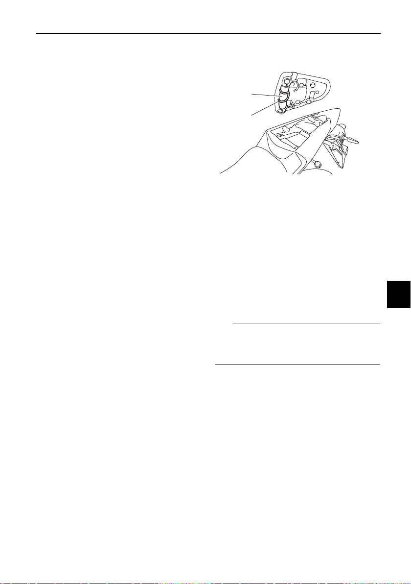
Fuel tank overflow hose
Before operating the vehicle:
z Check the fuel tank overflow hose
connection.
z Check the fuel tank overflow hose
for cracks or damage, and replace
it if necessary.
z Make sure that the end of the fuel
tank overflow hose is not blocked,
and clean it if necessary.
z Make sure that the end of the fuel
tank overflow hose is positioned
as shown.
TIP
See page 7-8 for canister information.
EAU13435
Catalytic converter
The exhaust system contains catalytic
converter(s) to reduce harmful exhaust
emissions.
WARNING
EWA10863
The exhaust system is hot after op-
eration. To prevent a fire hazard or
burns:
z Do not park the vehicle near
possible fire hazards such as
grass or other materials that
easily burn.
z Park the vehicle in a place
where pedestrians or children
are not likely to touch the hot
exhaust system.
z Make sure that the exhaust sys-
tem has cooled down before
doing any maintenance work.
z Do not allow the engine to idle
more than a few minutes. Long
idling can cause a build-up of
heat.
1. Fuel tank overflow hose
2. Fuel tank breather hose
1
Instrument and control functions
4-18
4
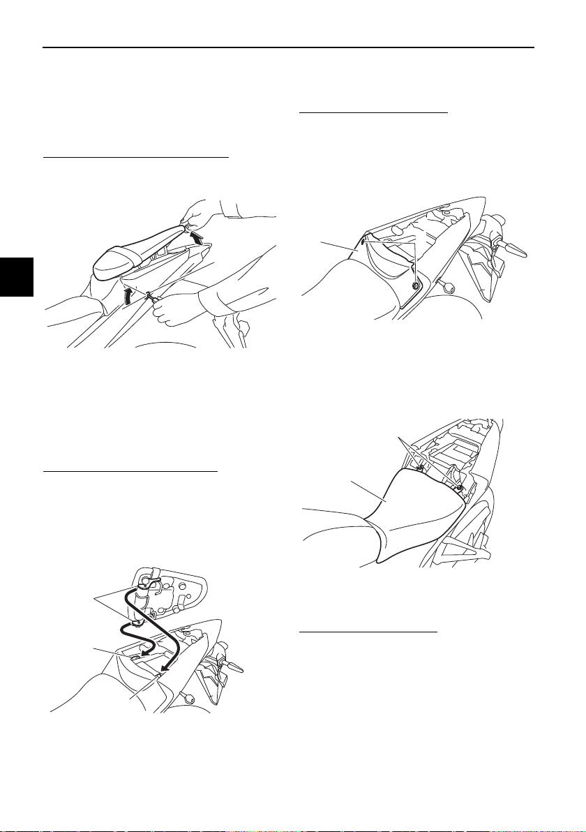
EAU62622
Seats
Passenger seat
To remove the passenger seat
1. Insert the key into the seat lock,
and then turn it clockwise.
2. While holding the key in that posi-
tion, lift the rear of the passenger
seat and pull it backward.
To install the passenger seat
1. Insert the projections on the front
of the passenger seat into the seat
holders as shown, and then push
the rear of the seat down to lock it
in place.
2. Remove the key.
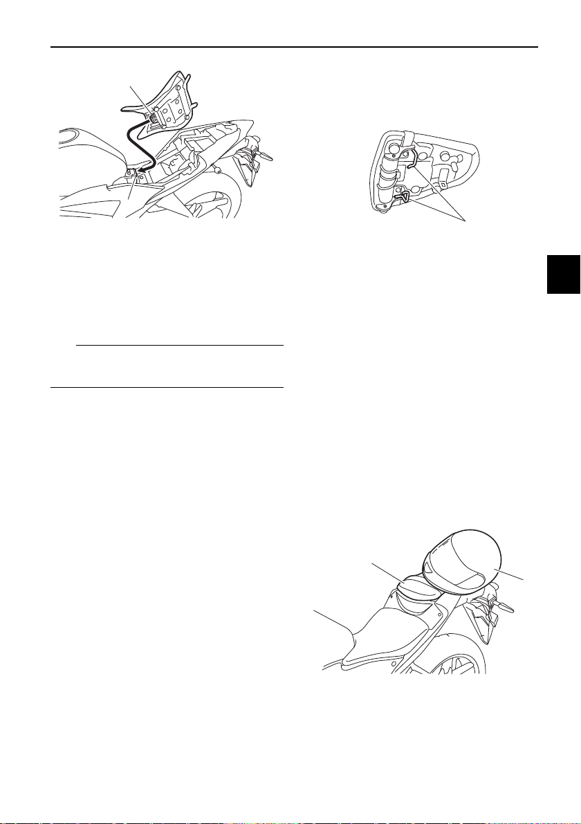
Rider seat
To remove the rider seat
1. Remove the passenger seat.
2. Remove the center cover by re-
moving the screws.
3. Remove the rider seat by remov-
ing the bolts. Lift the rear of the
rider seat and pull it backward.
To install the rider seat
1. Insert the projection on the front of
the rider seat into the seat holder
as shown, and then place the seat
in the original position.
1. Passenger seat lock
2. Unlock.
1. Projection
2. Seat holder
2
1
1
2
2
1. Center cover
2. Screw
1. Rider seat
2. Bolt
1
2
1
2
Instrument and control functions
4-19
4
2. Install the rider seat bolts.
3. Install the center cover by install-
ing the screws.
4. Install the passenger seat.
TIP
Make sure that the seats are properly
secured before riding.
EAU62930
Helmet holders
The helmet holders are located on the
bottom of the passenger seat.
To secure a helmet to a helmet hold-
er
1. Remove the passenger seat. (See
page 4-18.)
2. Attach a helmet to a helmet hold-
er, and then securely install the
passenger seat. WARNING! Nev-
er ride with a helmet attached to
the helmet holder, since the hel-
met may hit objects, causing
loss of control and possibly an
accident.
[EWA10162]
1. Projection
2. Seat holder
1
2
1. Helmet holder
1. Helmet
2. Passenger seat
1
1
2
Instrument and control functions
4-20
4
To release a helmet from a helmet
holder
Remove the passenger seat, remove
the helmet from the helmet holder, and
then install the seat.
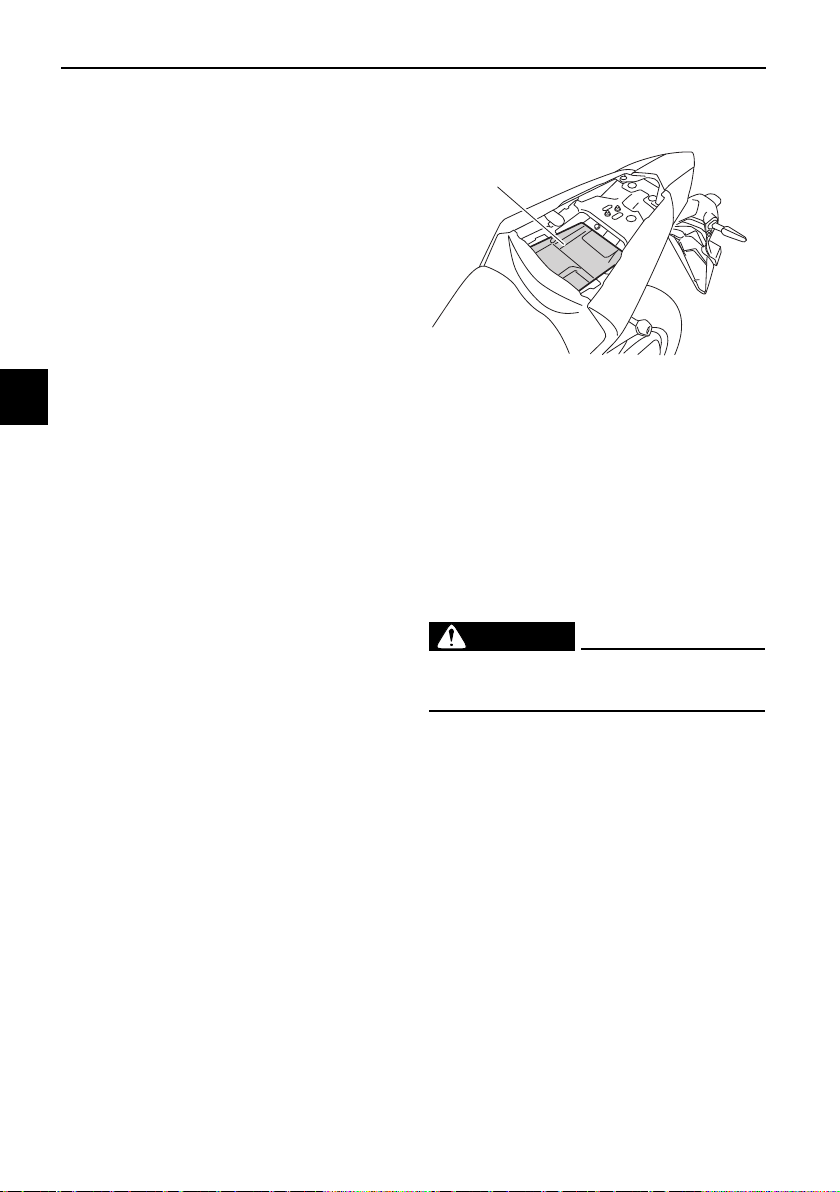
EAU62550
Storage compartment
The storage compartment is located
under the passenger seat. (See page
4-18.)
When storing documents or other
items in the storage compartment, be
sure to wrap them in a plastic bag so
that they will not get wet. When wash-
ing the vehicle, be careful not to let any
water enter the storage compartment.
WARNING
EWA15401
Do not exceed the maximum load of
160 kg (353 lb) for the vehicle.
1. Storage compartment
1
Instrument and control functions
4-21
4
EAU68143
Adjusting the shock absorber
assembly
This shock absorber assembly is
equipped with a spring preload adjust-
ing ring.
NOTICE
ECA10102
To avoid damaging the mechanism,
do not attempt to turn beyond the
maximum or minimum settings.
Adjust the spring preload as follows.
TIP
For ABS models, remove the drive
chain guard by removing the bolts and
collars.
Turn the adjusting ring in direction (a)
to increase the spring preload.
Turn the adjusting ring in direction (b)
to decrease the spring preload.
z Align the appropriate notch in the
adjusting ring with the position in-
dicator on the shock absorber.
z Use the special wrench and the
extension bar included in the tool
kit to make the adjustment.
TIP
For ABS models, be sure to install the
drive chain guard by installing the col-
lars and bolts, and then tighten the
bolts to the specified torque.
1. Drive chain guard
2. Bolt and collar
2
1
1. Extension bar
2. Special wrench
3. Spring preload adjusting ring
4. Position indicator
Spring preload setting:
Minimum (soft):
1
Standard:
4
Maximum (hard):
7
Tightening torque:
Drive chain guard bolt:
10 N·m (1.0 kgf·m, 7.4 lb·ft)
7
6
5
4
3
2
1
4
(b)
(a)
3
2
1
Instrument and control functions
4-22
4
EAU84680
Luggage strap holders
Use the indicated strap points to se-
cure luggage ties to the vehicle.
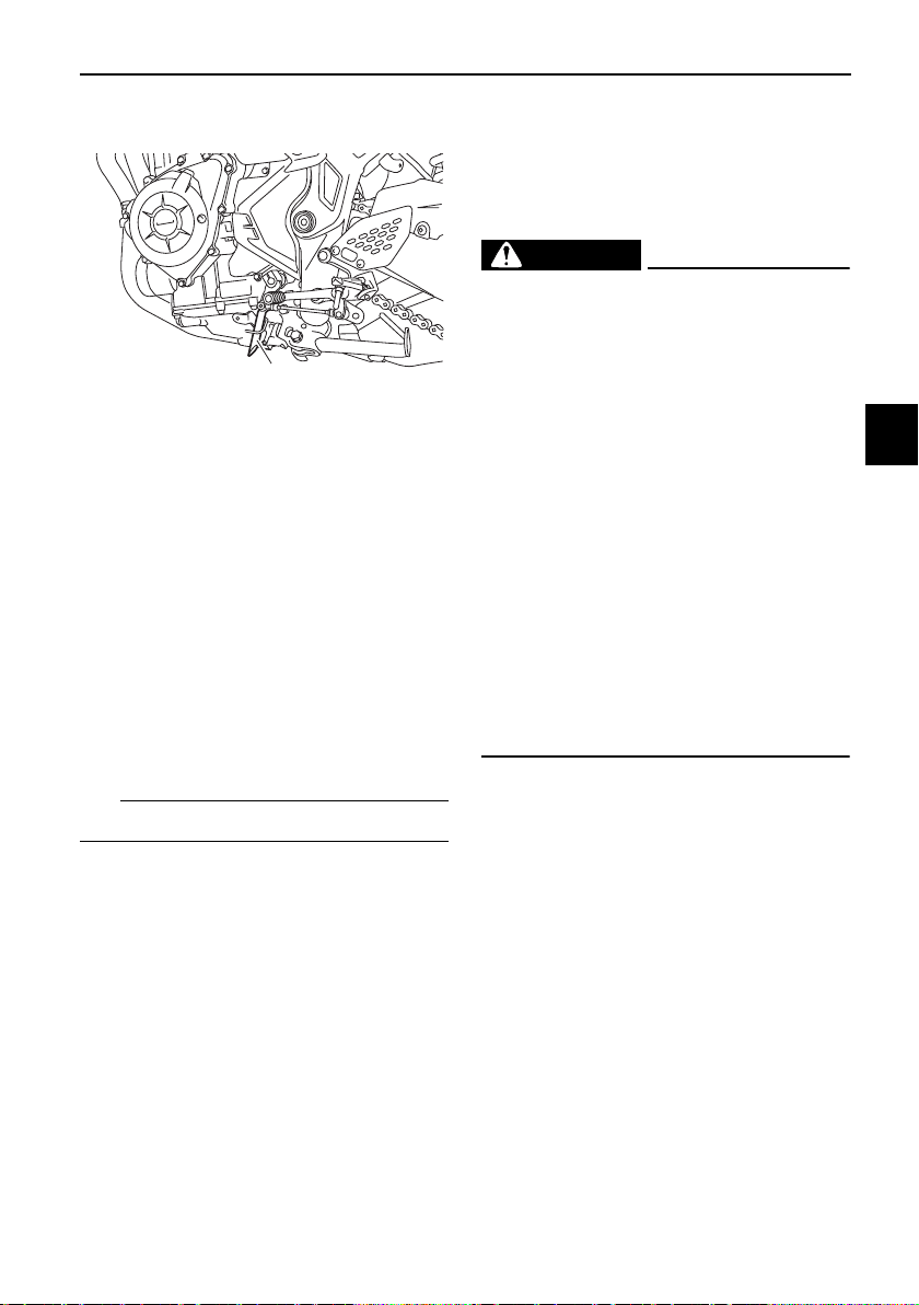
EAU15306
Sidestand
The sidestand is located on the left
side of the frame. Raise the sidestand
or lower it with your foot while holding
the vehicle upright.
TIP
The built-in sidestand switch is part of
the ignition circuit cut-off system,
which cuts the ignition in certain situa-
tions. (See the following section for an
explanation of the ignition circuit cut-
off system.)
WARNING
EWA10242
The vehicle must not be ridden with
the sidestand down, or if the side-
stand cannot be properly moved up
(or does not stay up), otherwise the
sidestand could contact the ground
and distract the operator, resulting
in a possible loss of control.
Yamaha’s ignition circuit cut-off
system has been designed to assist
the operator in fulfilling the respon-
sibility of raising the sidestand be-
fore starting off. Therefore, check
this system regularly and have a
Yamaha dealer repair it if it does not
function properly.
1. Luggage strap holder
1

Instrument and control functions
4-23
4
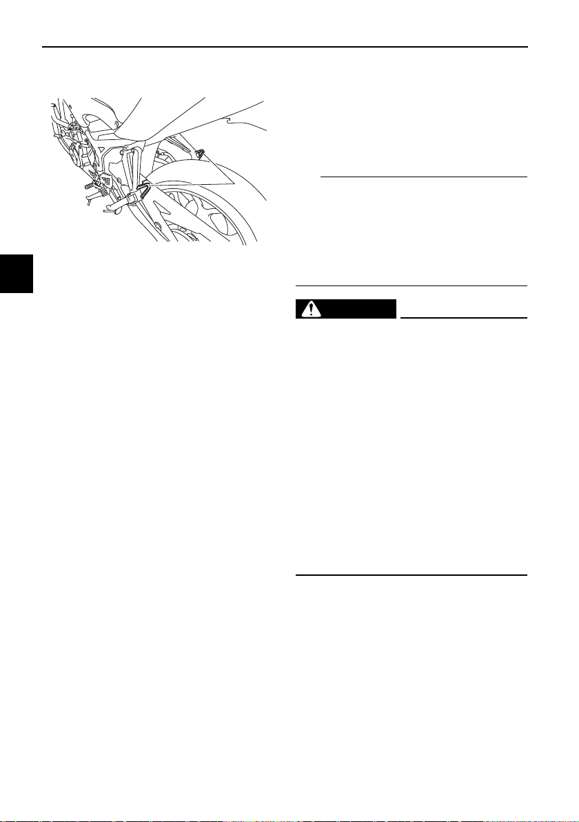
EAU64051
Ignition circuit cut-off system
This system prevents in-gear engine
starts unless the clutch lever is pulled
and the sidestand is up. Also, it will
stop the running engine should the
sidestand be lowered while the trans-
mission is in gear.
Periodically check the system via the
following procedure.
TIP
z This check is most reliable if per-
formed with a warmed-up engine.
z See pages 4-1 for switch opera-
tion information.
Instrument and control functions
4-24
4
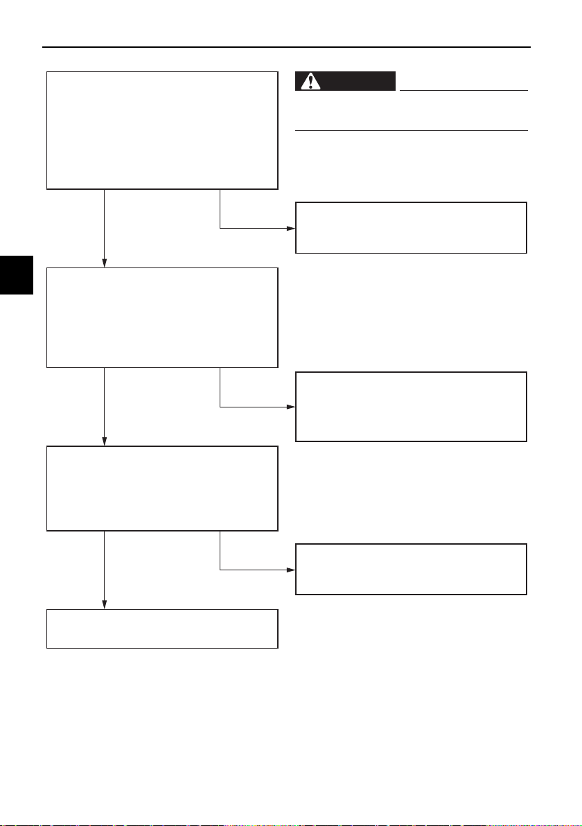
With the engine turned off:
1. Move the sidestand down.
2. Set engine stop switch to run position.
3. Turn main switch to on position.
4. Shift transmission into neutral.
5. Push the start switch.
Does the engine start?
With the engine still running:
6. Move the sidestand up.
7. Pull the clutch lever.
8. Shift transmission into gear.
9. Move the sidestand down.
Does the engine stall?
After the engine has stalled:
10. Move the sidestand up.
11. Pull the clutch lever.
12. Push the start switch.
Does the engine start?
The system is OK. The motorcycle can
be ridden.
The neutral switch may not be working.
The motorcycle should not be ridden
until checked by a Yamaha dealer.
The sidestand switch may not be
working.
The motorcycle should not be ridden
until checked by a Yamaha dealer.
The clutch switch may not be working.
The motorcycle should not be ridden
until checked by a Yamaha dealer.
WARNING
If a malfunction is found, have the
vehicle inspected before riding.
YES NO
YES NO
YES NO
For your safety – pre-operation checks
5-1
5
EAU63441
Inspect your vehicle each time you use it to make sure the vehicle is in safe oper-
ating condition. Always follow the inspection and maintenance procedures and
schedules described in the Owner’s Manual.
WARNING
EWA11152
Failure to inspect or maintain the vehicle properly increases the possibility
of an accident or equipment damage. Do not operate the vehicle if you find
any problem. If a problem cannot be corrected by the procedures provided
in this manual, have the vehicle inspected by a Yamaha dealer.
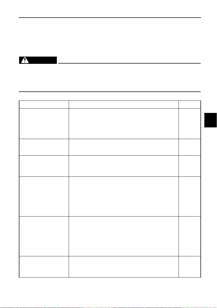
Before using this vehicle, check the following points:
ITEM CHECKS PAGE
Fuel
• Check fuel level in fuel tank.
• Refuel if necessary.
• Check fuel line for leakage.
• Check fuel tank breather hose and overflow hose for
obstructions, cracks or damage, and check hose con-
nections.
4-15,
4-17
Engine oil
• Check oil level in engine.
• If necessary, add recommended oil to specified level.
• Check vehicle for oil leakage.
7-8
Coolant
• Check coolant level in reservoir.
• If necessary, add recommended coolant to specified
level.
• Check cooling system for leakage.
7-12
Front brake
• Check operation.
• If soft or spongy, have Yamaha dealer bleed hydraulic
system.
• Check brake pads for wear.
• Replace if necessary.
• Check fluid level in reservoir.
• If necessary, add specified brake fluid to specified level.
• Check hydraulic system for leakage.
7-20,
7-21
Rear brake
• Check operation.
• If soft or spongy, have Yamaha dealer bleed hydraulic
system.
• Check brake pads for wear.
• Replace if necessary.
• Check fluid level in reservoir.
• If necessary, add specified brake fluid to specified level.
• Check hydraulic system for leakage.
7-20,
7-21
Clutch
• Check operation.
• Lubricate cable if necessary.
• Check lever free play.
• Adjust if necessary.
7-18
For your safety – pre-operation checks
5-2
5
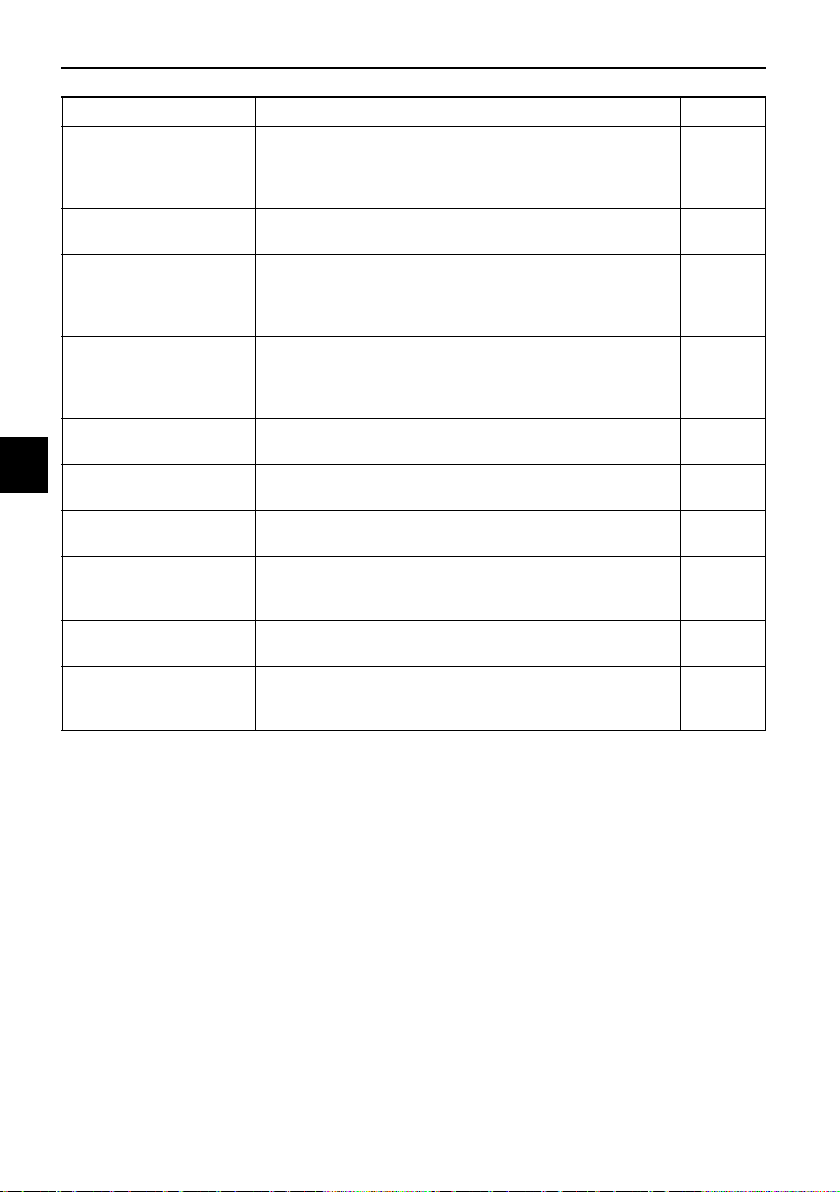
Throttle grip
• Make sure that operation is smooth.
• Check throttle grip free play.
• If necessary, have Yamaha dealer adjust throttle grip
free play and lubricate cable and grip housing.
7-15,
7-25
Control cables
• Make sure that operation is smooth.
• Lubricate if necessary.
7-25
Drive chain
• Check chain slack.
• Adjust if necessary.
• Check chain condition.
• Lubricate if necessary.
7-23,
7-24
Wheels and tires
•Check for damage.
• Check tire condition and tread depth.
• Check air pressure.
• Correct if necessary.
7-16,
7-18
Brake and shift pedals
• Make sure that operation is smooth.
• Lubricate pedal pivoting points if necessary.
7-26
Brake and clutch le-
vers
• Make sure that operation is smooth.
• Lubricate lever pivoting points if necessary.
7-26
Sidestand
• Make sure that operation is smooth.
• Lubricate pivot if necessary.
7-27
Chassis fasteners
• Make sure that all nuts, bolts and screws are properly
tightened.
• Tighten if necessary.
—
Instruments, lights,
signals and switches
• Check operation.
• Correct if necessary.
—
Sidestand switch
• Check operation of ignition circuit cut-off system.
• If system is not working correctly, have Yamaha dealer
check vehicle.
4-22
ITEM CHECKS PAGE
Operation and important riding points
6-1
6
EAU15952
Read the Owner’s Manual carefully to
become familiar with all controls. If
there is a control or function you do not
understand, ask your Yamaha dealer.
WARNING
EWA10272
Failure to familiarize yourself with
the controls can lead to loss of con-
trol, which could cause an accident
or injury.
EAU16842
Engine break-in
There is never a more important period
in the life of your engine than the period
between 0 and 1600 km (1000 mi). For
this reason, you should read the fol-
lowing material carefully.
Since the engine is brand new, do not
put an excessive load on it for the first
1600 km (1000 mi). The various parts in
the engine wear and polish themselves
to the correct operating clearances.
During this period, prolonged full-throt-
tle operation or any condition that
might result in engine overheating
must be avoided.
EAU17094
0–1000 km (0–600 mi)
Avoid prolonged operation above 7000
r/min. NOTICE: After 1000 km (600
mi) of operation, the engine oil must
be changed and the oil filter car-
tridge or element replaced.
[ECA10303]
1000–1600 km (600–1000 mi)
Avoid prolonged operation above 8400
r/min.
1600 km (1000 mi) and beyond
The vehicle can now be operated nor-
mally.
NOTICE
ECA10311
z Keep the engine speed out of
the tachometer red zone.
z If any engine trouble should oc-
cur during the engine break-in
period, immediately have a
Yamaha dealer check the vehi-
cle.
Operation and important riding points
6-2
6
EAU86620
Starting the engine
The ignition circuit cut-off system will
enable starting when:
z the transmission is in the neutral
position or
z the transmission is in gear, the
sidestand is up, and the clutch le-
ver is pulled.
To start the engine
1. Turn the main switch on and set
the engine stop switch to the run
position.
2. Confirm the indicator and warning
light(s) come on for a few sec-
onds, and the go off. (See page
4-2.)
TIP
z Do not start the engine if the en-
gine trouble warning light remains
on.
z The oil pressure warning light
should come on and stay on until
the engine is started.
z The ABS warning light should
come on and stay on until the ve-
hicle reaches a speed of 10 km/h
(6 mi/h).
NOTICE
ECA24110
If a warning or indicator light does
not work as described above, have a
Yamaha dealer check the vehicle.
3. Shift the transmission into the
neutral position.
4. Start the engine by pushing the
start switch.
5. Release the start switch when the
engine starts, or after 5 seconds.
Wait 10 seconds before pressing
the switch again to allow battery
voltage to restore.
NOTICE
ECA11043
For maximum engine life, never ac-
celerate hard when the engine is
cold!
Operation and important riding points
6-3
6
EAU48713
TIP
This model is equipped with:
z a lean angle sensor. This sensor
stops the engine in case of a turn-
over. In this case, the display will
indicate error code 30, but this is
not a malfunction. Turn the main
switch off and then on to clear the
error code. Failing to do so will
prevent the engine from starting
even though the engine will crank
when pushing the start switch.
z an engine auto-stop system. The
engine stops automatically if left
idling for 20 minutes. If the engine
stops, simply push the start
switch to restart the engine.
EAU16674
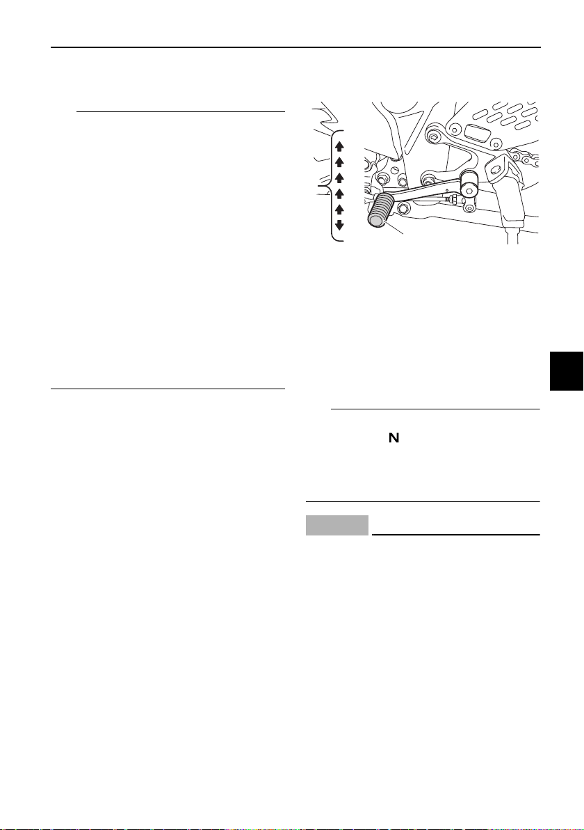
Shifting
Shifting gears lets you control the
amount of engine power available for
starting off, accelerating, climbing hills,
etc.
The gear positions are shown in the il-
lustration.
TIP
To shift the transmission into the neu-
tral position ( ), press the shift pedal
down repeatedly until it reaches the
end of its travel, and then slightly raise
it.
NOTICE
ECA10261
z Even with the transmission in
the neutral position, do not
coast for long periods of time
with the engine off, and do not
tow the motorcycle for long dis-
tances. The transmission is
properly lubricated only when
the engine is running. Inade-
quate lubrication may damage
the transmission.
z Always use the clutch while
changing gears to avoid dam-
aging the engine, transmission,
1. Gear positions
2. Shift pedal
2
1
1
N
2
3
4
5
6
Operation and important riding points
6-4
6
and drive train, which are not
designed to withstand the
shock of forced shifting.
EAU16682
To start out and accelerate
1. Pull the clutch lever to disengage
the clutch.
2. Shift the transmission into first
gear. The neutral indicator light
should go out.
3. Open the throttle gradually, and at
the same time, release the clutch
lever slowly.
4. At the recommended shift points
shown in the following table, close
the throttle, and at the same time,
quickly pull the clutch lever in.
5. Shift the transmission into second
gear. (Make sure not to shift the
transmission into the neutral posi-
tion.)
6. Open the throttle part way and
gradually release the clutch lever.
7. Follow the same procedure when
shifting to the next higher gear.
TIP
When shifting gears in normal operat-
ing conditions, use the recommended
shift points.
EAU58270
To decelerate
1. Release the throttle and apply
both the front and the rear brakes
smoothly to slow the motorcycle.
2. At the recommended shift points
shown in the following table, shift
to a lower gear.
3. When the motorcycle reaches 25
km/h (16 mph), the engine is about
to stall or runs roughly, pull the
clutch lever in, use the brakes to
slow the motorcycle, and continue
to downshift as necessary.
4. Once the motorcycle has
stopped, the transmission can be
shifted into the neutral position.
The neutral indicator light should
come on and then the clutch lever
can be released.
WARNING
EWA17380
z Improper braking can cause
loss of control or traction. Al-
ways use both brakes and apply
them smoothly.
z Make sure that the motorcycle
and the engine have sufficiently
slowed before shifting to a low-
er gear. Engaging a lower gear
when the vehicle or engine
speed is too high could make
the rear wheel lose traction or
the engine to over-rev. This
could cause loss of control, an
accident and injury. It could also
cause engine or drive train dam-
age.
EAU64150
Recommended shift points
The recommended shift points during
acceleration and deceleration are
shown in the table below.
Shift up points:
1st → 2nd: 20 km/h (12 mph)
2nd → 3rd: 30 km/h (19 mph)
3rd → 4th: 40 km/h (25 mph)
4th → 5th: 50 km/h (31 mph)
5th → 6th: 60 km/h (37 mph)
Shift down points:
6th → 5th: 45 km/h (28 mph)
5th → 4th: 35 km/h (22 mph)
4th → 3rd: 25 km/h (16 mph)

Operation and important riding points
6-5
6
EAU17214
Parking
When parking, stop the engine, and
then remove the key from the main
switch.
WARNING
EWA10312
z Since the engine and exhaust
system can become very hot,
park in a place where pedestri-
ans or children are not likely to
touch them and be burned.
z Do not park on a slope or on soft
ground, otherwise the vehicle
may overturn, increasing the
risk of a fuel leak and fire.
z Do not park near grass or other
flammable materials which
might catch fire.
Periodic maintenance and adjustment
7-1
7
EAU17246
Periodic inspection, adjustment, and
lubrication will keep your vehicle in the
safest and most efficient condition
possible. Safety is an obligation of the
vehicle owner/operator. The most im-
portant points of vehicle inspection,
adjustment, and lubrication are ex-
plained on the following pages.
The intervals given in the periodic
maintenance charts should be simply
considered as a general guide under
normal riding conditions. However, de-
pending on the weather, terrain, geo-
graphical location, and individual use,
the maintenance intervals may need to
be shortened.
WARNING
EWA10322
Failure to properly maintain the vehi-
cle or performing maintenance ac-
tivities incorrectly may increase
your risk of injury or death during
service or while using the vehicle. If
you are not familiar with vehicle ser-
vice, have a Yamaha dealer perform
service.
WARNING
EWA15123
Turn off the engine when performing
maintenance unless otherwise
specified.
z A running engine has moving
parts that can catch on body
parts or clothing and electrical
parts that can cause shocks or
fires.
z Running the engine while ser-
vicing can lead to eye injury,
burns, fire, or carbon monoxide
poisoning – possibly leading to
death. See page 2-3 for more in-
formation about carbon monox-
ide.
WARNING
EWA15461
Brake discs, calipers, drums, and
linings can become very hot during
use. To avoid possible burns, let
brake components cool before
touching them.
Periodic maintenance and adjustment
7-2
7
EAU17303
Emission controls not only function to
ensure cleaner air, but are also vital to
proper engine operation and maximum
performance. In the following periodic
maintenance charts, the services relat-
ed to emissions control are grouped
separately. These services require
specialized data, knowledge, and
equipment. Maintenance, replace-
ment, or repair of the emission control
devices and systems may be per-
formed by any repair establishment or
individual that is certified (if applicable).
Yamaha dealers are trained and
equipped to perform these particular
services.
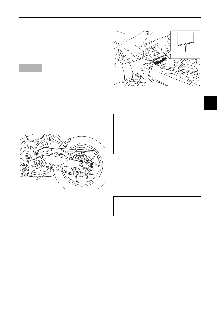
EAU85230
Tool kit
The tool kit is in the location shown.
The information included in this manual
and the tools provided in the tool kit are
intended to assist you in the perfor-
mance of preventive maintenance and
minor repairs. However, a torque
wrench and other tools are necessary
to perform certain maintenance work
correctly.
TIP
If you do not have the tools or experi-
ence required for a particular job, have
your Yamaha dealer perform it for you.
1. Tool kit
2. O-ring
1
2
Periodic maintenance and adjustment
7-3
7
EAU48471
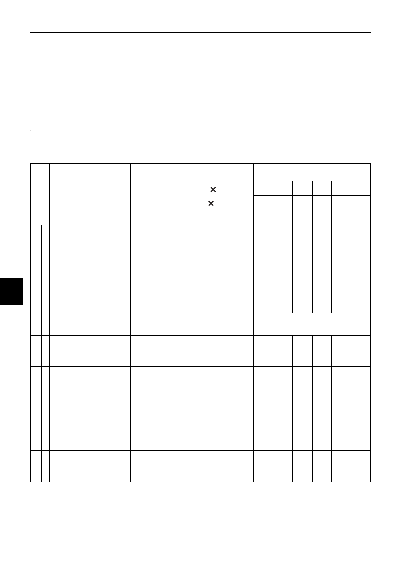
TIP
z From 19000 mi (31000 km) or 36 months, repeat the maintenance intervals
starting from 7000 mi (11000 km) or 12 months.
z Items marked with an asterisk require special tools, data and technical skills,
have a Yamaha dealer perform the service.
EAU69091
Periodic maintenance chart for the emission control system
No. ITEM
ROUTINE
0.6 4 7 10 13 16
1 6 11 16 21 26
1 6 12 18 24 30
1 * Fuel line
• Check fuel hoses for cracks or
damage.
• Replace if necessary.
√√√√√
2Spark plugs
• Check condition.
• Adjust gap and clean.
• Replace at 7000 mi (11000 km)
or 12 months and thereafter ev-
ery 6000 mi (10000 km) or 12
months.
√
Re
pla
ce.
√
Re
pla
ce.
√
3 * Valve clearance
• Check and adjust valve clear-
ance when engine is cold.
Every 26600 mi (42000 km)
4 *
Crankcase breather
system
• Check breather hose for cracks
or damage.
• Replace if necessary.
√√√√√
5 * Fuel injection • Adjust synchronization. √√√√√
6 * Exhaust system
• Check for leakage.
• Tighten if necessary.
• Replace gasket(s) if necessary.
√√√√√
7 *
Evaporative emis-
sion control sys-
tem (for California
only)
• Check control system for dam-
age.
• Replace if necessary.
√√
8 *
Air induction sys-
tem
• Check the air cut-off valve, reed
valve, and hose for damage.
• Replace any damaged parts.
√√
1000 mi
1000 km
month
INITIAL
ODOMETER READINGS
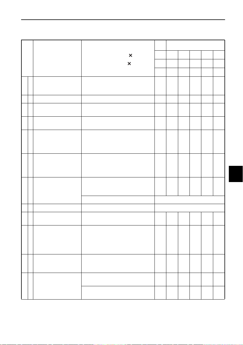
Periodic maintenance and adjustment
7-4
7
EAU69142
General maintenance and lubrication chart
No. ITEM
ROUTINE
0.6 4 7 101316
1 6 11 16 21 26
1 6 12 18 24 30
1 *
Diagnostic system
check
• Perform dynamic inspection
using Yamaha diagnostic tool.
• Check the error codes.
√√√√√√
2 Air filter element • Replace. √
3
Air filter check
hose
• Clean. √√√√√√
4 * Clutch
• Check operation.
• Adjust or replace cable.
√√√√√√
5 * Front brake
• Check operation, fluid level,
and for fluid leakage.
• Replace brake pads if neces-
sary.
√√√√√√
6 * Rear brake
• Check operation, fluid level,
and for fluid leakage.
• Replace brake pads if neces-
sary.
√√√√√√
7 * Brake hose
• Check for cracks or damage.
• Check for correct routing and
clamping.
√√√√√
• Replace. Every 4 years
8 * Brake fluid • Change. Every 2 years
9 * Wheels
• Check runout and for damage.
• Replace if necessary.
√√√√√
10 * Tires
• Check tread depth and for
damage.
• Replace if necessary.
• Check air pressure.
• Correct if necessary.
√√√√√
11 * Wheel bearings
• Check bearings for smooth op-
eration.
• Replace if necessary.
√√√√√
12 *
Swingarm pivot
bearings
• Check bearing assemblies for
looseness.
√
• Moderately repack with lithium-
soap-based grease.
√
1000 mi
1000 km
m
o
n
t
h
INITIAL
ODOMETER READINGS

Periodic maintenance and adjustment
7-5
7
13 Drive chain
• Check chain slack, alignment
and condition.
• Adjust and lubricate chain with
a special O-ring chain lubricant
thoroughly.
Every 500 mi (800 km) and after
washing the motorcycle, riding
in the rain or riding in wet areas
14 * Steering bearings
• Check bearing assemblies for
looseness.
• Moderately repack with lithium-
soap-based grease.
√√√√
Re
pa
ck.
√
15 * Chassis fasteners
• Check all chassis fitting and
fasteners.
• Correct if necessary.
√√√√√
16
Brake lever pivot
shaft
• Apply silicone grease lightly. √√√√√
17
Brake pedal pivot
shaft
• Apply lithium-soap-based
grease lightly.
√√√√√
18
Clutch lever pivot
shaft
• Apply lithium-soap-based
grease lightly.
√√√√√
19
Shift pedal pivot
shaft
• Apply lithium-soap-based
grease lightly.
√√√√√
20 Sidestand pivot
• Check operation.
• Apply lithium-soap-based
grease lightly.
√√√√√
21 * Sidestand switch
• Check operation and replace if
necessary.
√√√√√√
22 * Front fork
• Check operation and for oil
leakage.
• Replace if necessary.
√√√√√
23 *
Shock absorber as-
sembly
• Check operation and for oil
leakage.
• Replace if necessary.
√√√√√
24 En
gine oil
• Change. (See pages 4-4 and
7-8.)
√
When the oil change indi-
cator flashes
• Check oil level and vehicle for
oil leakage.
√√√√√√
25
Engine oil filter car-
tridge
• Replace. √√√
No. ITEM
ROUTINE
0.6 4 7 10 13 16
1 6 11 16 21 26
1 6 12 18 24 30
1000 mi
1000 km
month
INITIAL
ODOMETER READINGS
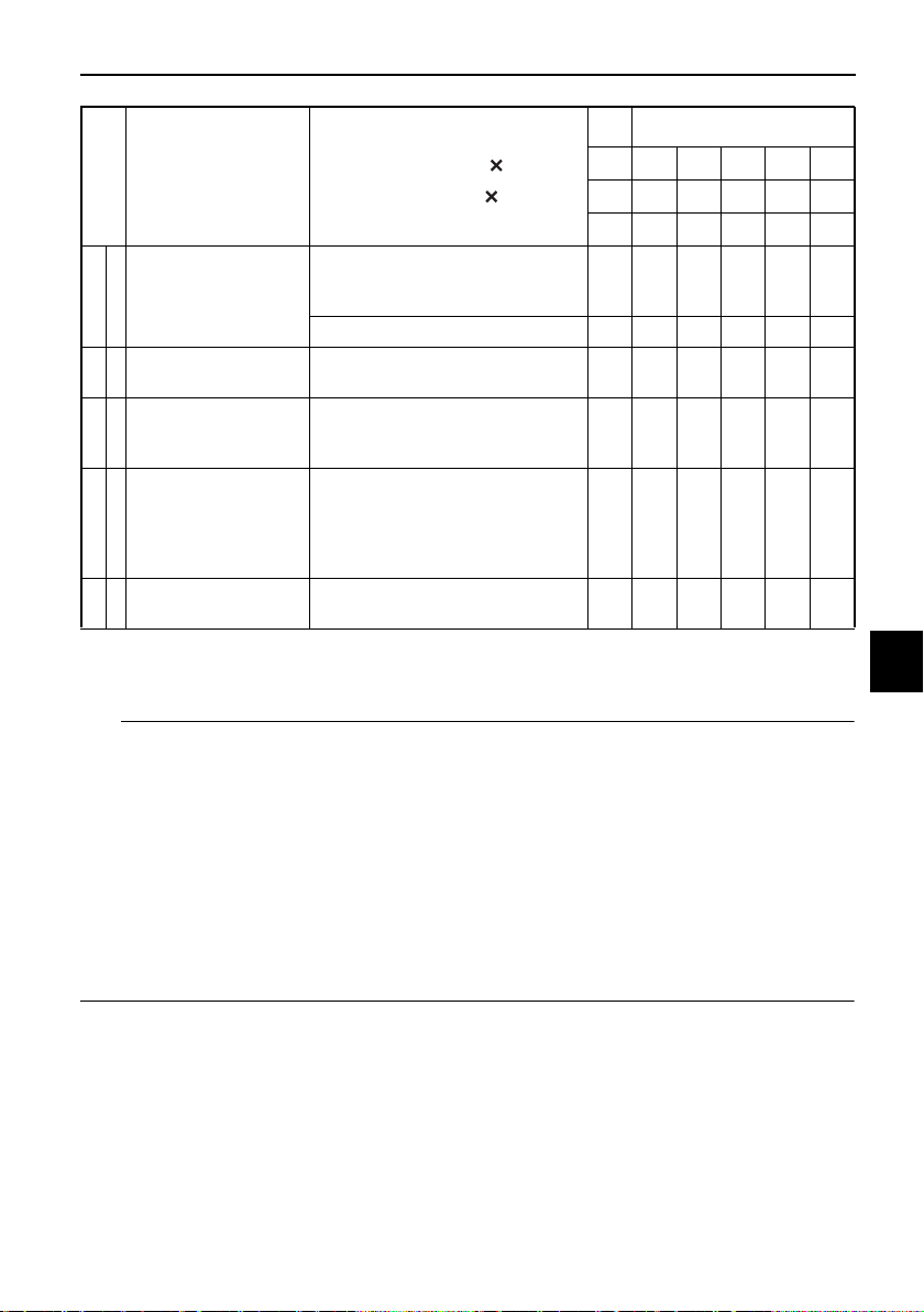
Periodic maintenance and adjustment
7-6
7
EAU17653
TIP
z Air filter
• This model uses a disposable oil-coated paper element. This element can-
not be cleaned with compressed air, doing so will only damage it.
• Replace the air filter more frequently if you often ride in the rain or dusty
conditions.
z Hydraulic brake service
• Regularly check the brake fluid levels. Replenish as necessary.
• Every two years replace the internal components of the brake master cyl-
inders and calipers, and change the brake fluid.
• Replace the brake hoses every four years or sooner if cracked or damaged.
26 * Cooling system
• Check hoses for cracks or
damage.
• Replace if necessary.
√√√√√
• Change coolant. √
27 *
Front and rear
brake switches
• Check operation. √√√√√√
28 * Control cables
• Apply Yamaha cable lubricant
or other suitable cable lubricant
thoroughly.
√√√√√√
29 * Throttle grip
• Check operation.
• Check throttle grip free play,
and adjust if necessary.
• Lubricate cable and grip hous-
ing.
√√√√√
30 *
Lights, signals and
switches
• Check operation.
• Adjust headlight beam.
√√√√√√
No. ITEM
ROUTINE
0.6 4 7 101316
1 6 11 16 21 26
1 6 12 18 24 30
1000 mi
1000 km
m
o
n
t
h
INITIAL
ODOMETER READINGS
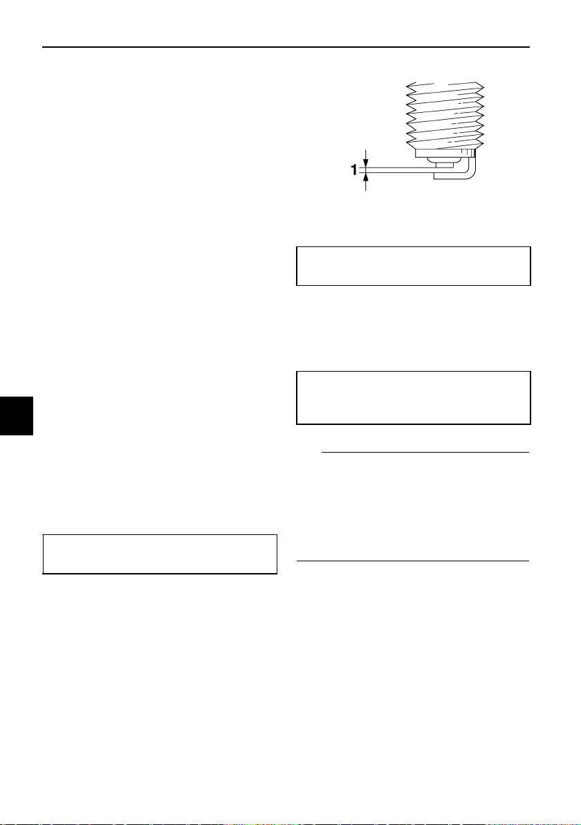
Periodic maintenance and adjustment
7-7
7
EAU19643
Checking the spark plugs
The spark plugs are important engine
components, which should be
checked periodically, preferably by a
Yamaha dealer. Since heat and depos-
its will cause any spark plug to slowly
erode, they should be removed and
checked in accordance with the peri-
odic maintenance and lubrication
chart. In addition, the condition of the
spark plugs can reveal the condition of
the engine.
The porcelain insulator around the
center electrode of each spark plug
should be a medium-to-light tan (the
ideal color when the vehicle is ridden
normally), and all spark plugs installed
in the engine should have the same
color. If any spark plug shows a dis-
tinctly different color, the engine could
be operating improperly. Do not at-
tempt to diagnose such problems
yourself. Instead, have a Yamaha deal-
er check the vehicle.
If a spark plug shows signs of elec-
trode erosion and excessive carbon or
other deposits, it should be replaced.
Before installing a spark plug, the
spark plug gap should be measured
with a wire thickness gauge and, if
necessary, adjusted to specification.
Clean the surface of the spark plug
gasket and its mating surface, and
then wipe off any grime from the spark
plug threads.
TIP
If a torque wrench is not available
when installing a spark plug, a good
estimate of the correct torque is 1/4–
1/2 turn past finger tight. However, the
spark plug should be tightened to the
specified torque as soon as possible.
Specified spark plug:
NGK/CR8E
1. Spark plug gap
Spark plug gap:
0.7–0.8 mm (0.028–0.031 in)
Tightening torque:
Spark plug:
13 N·m (1.3 kgf·m, 9.6 lb·ft)
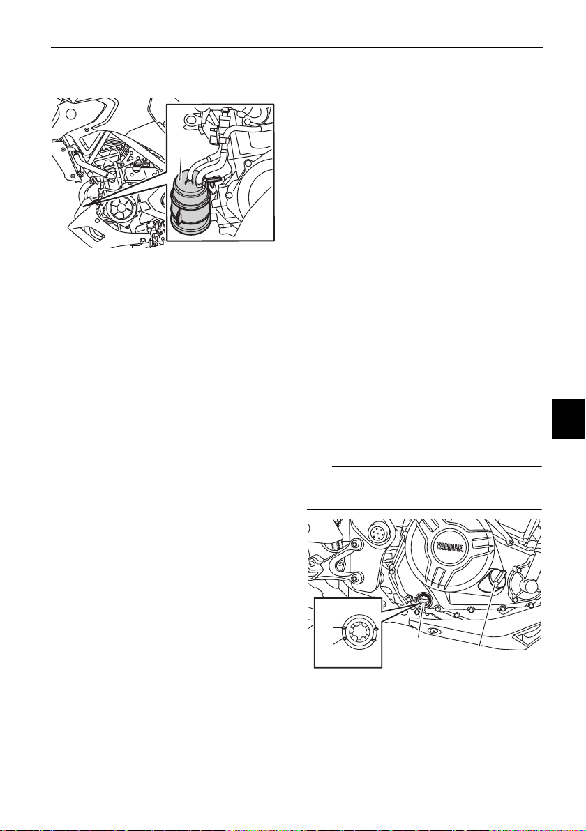
Periodic maintenance and adjustment
7-8
7
EAU36112
Canister
This model is equipped with a canister
to prevent the discharging of fuel vapor
into the atmosphere. Before operating
this vehicle, make sure to check the
following:
z Check each hose connection.
z Check each hose and canister for
cracks or damage. Replace if
damaged.
z Make sure that the canister
breather is not blocked, and if
necessary, clean it.
EAUN1150
Engine oil and oil filter car-
tridge
The engine oil level should be checked
before each ride. In addition, the oil
must be changed and the oil filter car-
tridge replaced at the intervals speci-
fied in the periodic maintenance and
lubrication chart.
To check the engine oil level
1. Place the vehicle on a level sur-
face and hold it in an upright posi-
tion. A slight tilt to the side can
result in a false reading.
2. Start the engine, warm it up for
several minutes, and then turn it
off.
3. Wait a few minutes until the oil set-
tles, and then check the oil level
through the engine oil level check
window located at the bottom-
right side of the crankcase.
TIP
The engine oil should be between the
minimum and maximum level marks.
1. Canister
1
1. Engine oil filler cap
2. Engine oil level check window
3. Maximum level mark
4. Minimum level mark
3
4
1
2
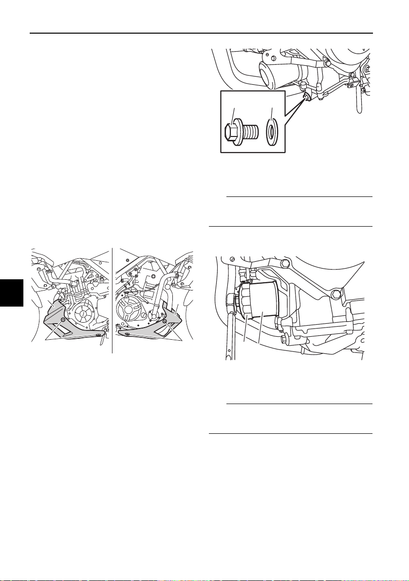
Periodic maintenance and adjustment
7-9
7
4. If the engine oil is below the mini-
mum level mark, add sufficient oil
of the recommended type to raise
it to the correct level.
To change the engine oil (with or
without oil filter cartridge replace-
ment)
1. Place the vehicle on a level sur-
face.
2. Start the engine, warm it up for
several minutes, and then turn it
off.
3. Place an oil pan under the engine
to collect the used oil.
4. Remove the cowling by removing
the bolts.
5. Remove the engine oil filler cap,
the engine oil drain bolt and its
gasket to drain the oil from the
crankcase.
TIP
Skip steps 6–8 if the oil filter cartridge
is not being replaced.
6. Remove the oil filter cartridge with
an oil filter wrench.
TIP
An oil filter wrench is available at a
Yamaha dealer.
7. Apply a thin coat of clean engine
oil to the O-ring of the new oil filter
cartridge.
1. Cowling
2. Bolt
2
2
1
1
1. Engine oil drain bolt
2. Gasket
1. Oil filter wrench
2. Oil filter cartridge
12
1
2
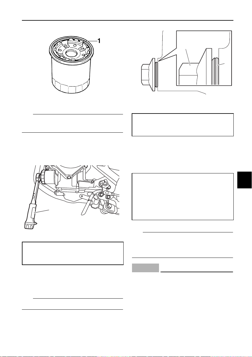
Periodic maintenance and adjustment
7-10
7
TIP
Make sure that the O-ring is properly
seated.
8. Install the new oil filter cartridge
with an oil filter wrench, and then
tighten it to the specified torque
with a torque wrench.
9. Install the engine oil drain bolt and
its new gasket, and then tighten
the bolt to the specified torque.
TIP
Install the new gasket as shown.
10. Refill with the specified amount of
the recommended engine oil, and
then install and tighten the oil filler
cap.
TIP
Be sure to wipe off spilled oil on any
parts after the engine and exhaust sys-
tem have cooled down.
NOTICE
ECA11621
z In order to prevent clutch slip-
page (since the engine oil also
lubricates the clutch), do not
mix any chemical additives. Do
not use oils with a diesel speci-
fication of “CD” or oils of a high-
er quality than specified. In
1. O-ring
1. Torque wrench
Tightening torque:
Oil filter cartridge:
17 N·m (1.7 kgf·m, 13 lb·ft)
1
1. Engine oil drain bolt
2. Gasket
Tightening torque:
Engine oil drain bolt:
20 N·m (2.0 kgf·m, 15 lb·ft)
Recommended engine oil:
See page 9-1.
Oil quantity:
Oil change:
1.80 L (1.90 US qt, 1.58 Imp.qt)
With oil filter removal:
2.10 L (2.22 US qt, 1.85 Imp.qt)
2
1
Periodic maintenance and adjustment
7-11
7
addition, do not use oils labeled
“ENERGY CONSERVING II” or
higher.
z Make sure that no foreign mate-
rial enters the crankcase.
11. Install the cowling by installing the
bolts.
12. Start the engine, and then let it idle
for several minutes while checking
it for oil leakage. If oil is leaking,
immediately turn the engine off
and check for the cause.
TIP
After the engine is started, the engine
oil pressure warning light should go off.
NOTICE
ECA20860
If the oil pressure warning light flick-
ers or remains on even if the oil level
is correct, immediately turn the en-
gine off and have a Yamaha dealer
check the vehicle.
13. Turn the engine off, wait a few
minutes until the oil settles, and
then check the oil level and cor-
rect it if necessary.
EAU85450
Why Yamalube
YAMALUBE oil is a Genuine YAMAHA
Part born of the engineers’ passion
and belief that engine oil is an impor-
tant liquid engine component. We form
teams of specialists in the fields of me-
chanical engineering, chemistry, elec-
tronics and track testing, and have
them develop the engine together with
the oil it will use. Yamalube oils take full
advantage of the base oil’s qualities
and blend in the ideal balance of addi-
tives to make sure the final oil clears
our performance standards. Thus,
Yamalube mineral, semisynthetic and
synthetic oils have their own distinct
characters and value. Yamaha’s expe-
rience gained over many years of re-
search and development into oil since
the 1960’s helps make Yamalube the
best choice for your Yamaha engine.
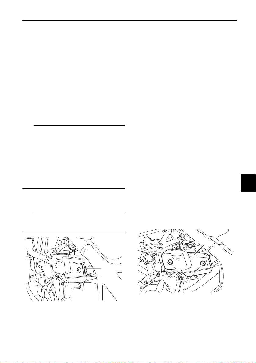
Periodic maintenance and adjustment
7-12
7
EAU20071
Coolant
The coolant level should be checked
before each ride. In addition, the cool-
ant must be changed at the intervals
specified in the periodic maintenance
and lubrication chart.
EAU38176
To check the coolant level
1. Place the vehicle on a level sur-
face and hold it in an upright posi-
tion.
TIP
z The coolant level must be
checked on a cold engine since
the level varies with engine tem-
perature.
z Make sure that the vehicle is posi-
tioned straight up when checking
the coolant level. A slight tilt to the
side can result in a false reading.
2. Check the coolant level in the
coolant reservoir.
TIP
The coolant should be between the
minimum and maximum level marks.
3. If the coolant is at or below the
minimum level mark, remove the
coolant reservoir cover by remov-
ing the bolts, remove the coolant
reservoir cap, and then add cool-
ant to the maximum level mark.
WARNING! Remove only the
coolant reservoir cap. Never at-
tempt to remove the radiator
cap when the engine is hot.
[EWA15162] NOTICE: If coolant is not
available, use distilled water or
soft tap water instead. Do not
use hard water or salt water
since it is harmful to the engine.
If water has been used instead
of coolant, replace it with cool-
ant as soon as possible, other-
wise the cooling system will not
be protected against frost and
corrosion. If water has been
added to the coolant, have a
Yamaha dealer check the anti-
freeze content of the coolant as
soon as possible, otherwise the
effectiveness of the coolant will
be reduced.
[ECA10473]
1. Maximum level mark
2. Minimum level mark
3. Coolant reservoir
1
2
3
1. Bolt
2. Coolant reservoir cover
2
1
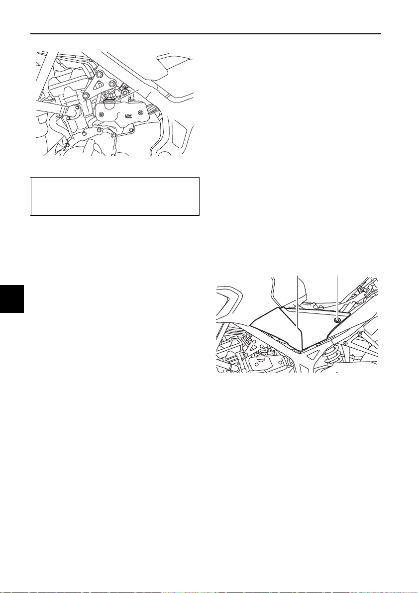
Periodic maintenance and adjustment
7-13
7
4. Install the reservoir cap, and then
install the coolant reservoir cover
by installing the bolts.
EAU33032
Changing the coolant
The coolant must be changed at the in-
tervals specified in the periodic mainte-
nance and lubrication chart. Have a
Yamaha dealer change the coolant.
WARNING! Never attempt to remove
the radiator cap when the engine is
hot.
[EWA10382]
EAUN1172
Replacing the air filter ele-
ment and cleaning the check
hose
The air filter element should be re-
placed at the intervals specified in the
periodic maintenance and lubrication
chart. Replace the air filter element
more frequently if you are riding in un-
usually wet or dusty areas. In addition,
the air filter check hose must be fre-
quently checked and cleaned if neces-
sary.
To replace the air filter element
1. Remove the rider seat. (See page
4-18.)
2. Remove the left side panel bolts.
3. Remove the left side panel by re-
moving the lower projection on the
panel from the slot, and then re-
moving the upper projection as
shown.
1. Coolant reservoir cap
Coolant reservoir capacity (up to
the maximum level mark):
0.25 L (0.26 US qt, 0.22 Imp.qt)
1
1. Left side panel
2. Bolt
2
1
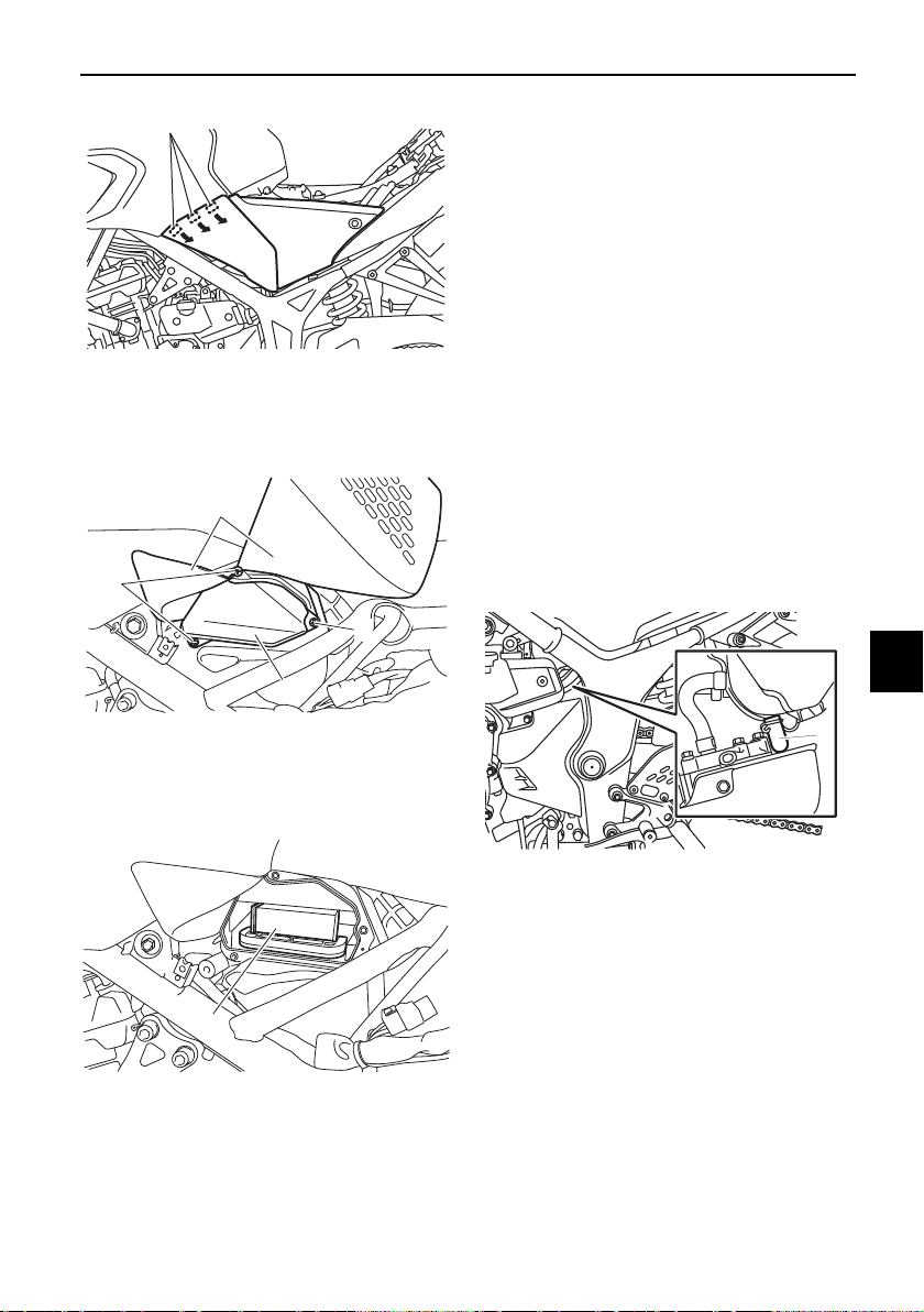
Periodic maintenance and adjustment
7-14
7
4. Lift up the rubber covers, and then
remove the air filter case cover by
removing the screws.
5. Pull the air filter element out.
6. Insert a new air filter element into
the air filter case. NOTICE: Make
sure that the air filter element is
properly seated in the air filter
case. The engine should never
be operated without the air filter
element installed, otherwise the
piston(s) and/or cylinder(s) may
become excessively worn.
[ECA10482]
7. Install the air filter case cover by
installing the screws, and then
place the rubber covers in their
original positions.
8. Place the left side panel in the
original position, and then install
the bolts.
9. Install the rider seat.
To clean the air filter check hose
1. Check the hose on the front of the
air filter case for accumulated dirt
or water.
2. If dirt or water is visible, remove
the hose, clean it, and then install
it.
1. Projection
1. Air filter case cover
2. Screw
3. Rubber cover
1. Air filter element
1
1
2
2
3
1
1. Air filter check hose
1
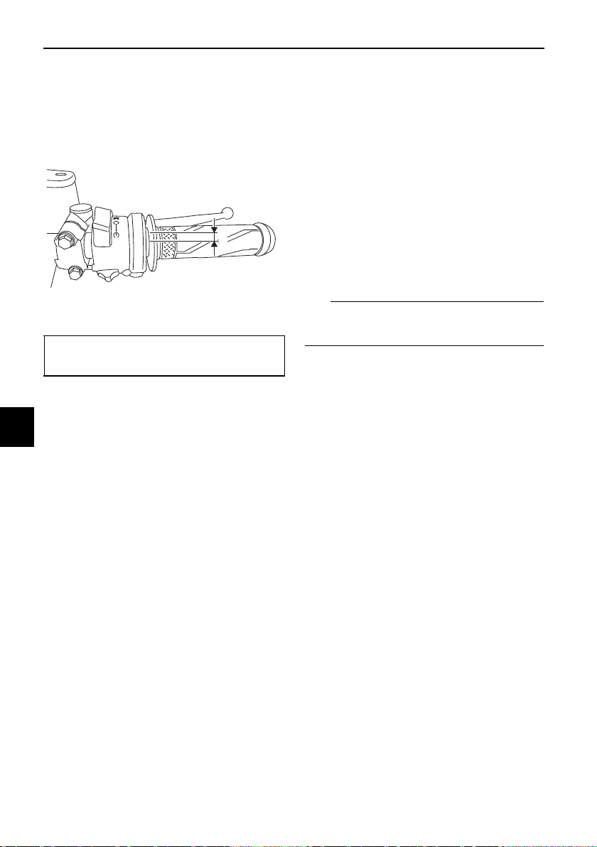
Periodic maintenance and adjustment
7-15
7
EAU21386
Checking the throttle grip free
play
Measure the throttle grip free play as
shown.
Periodically check the throttle grip free
play and, if necessary, have a Yamaha
dealer adjust it.
EAU21403
Valve clearance
The valves are an important engine
component, and since valve clearance
changes with use, they must be
checked and adjusted at the intervals
specified in the periodic maintenance
chart. Unadjusted valves can result in
improper air-fuel mixture, engine
noise, and eventually engine damage.
To prevent this from occurring, have
your Yamaha dealer check and adjust
the valve clearance at regular intervals.
TIP
This service must be performed when
the engine is cold.
1. Throttle grip free play
Throttle grip free play:
3.0–5.0 mm (0.12–0.20 in)
1
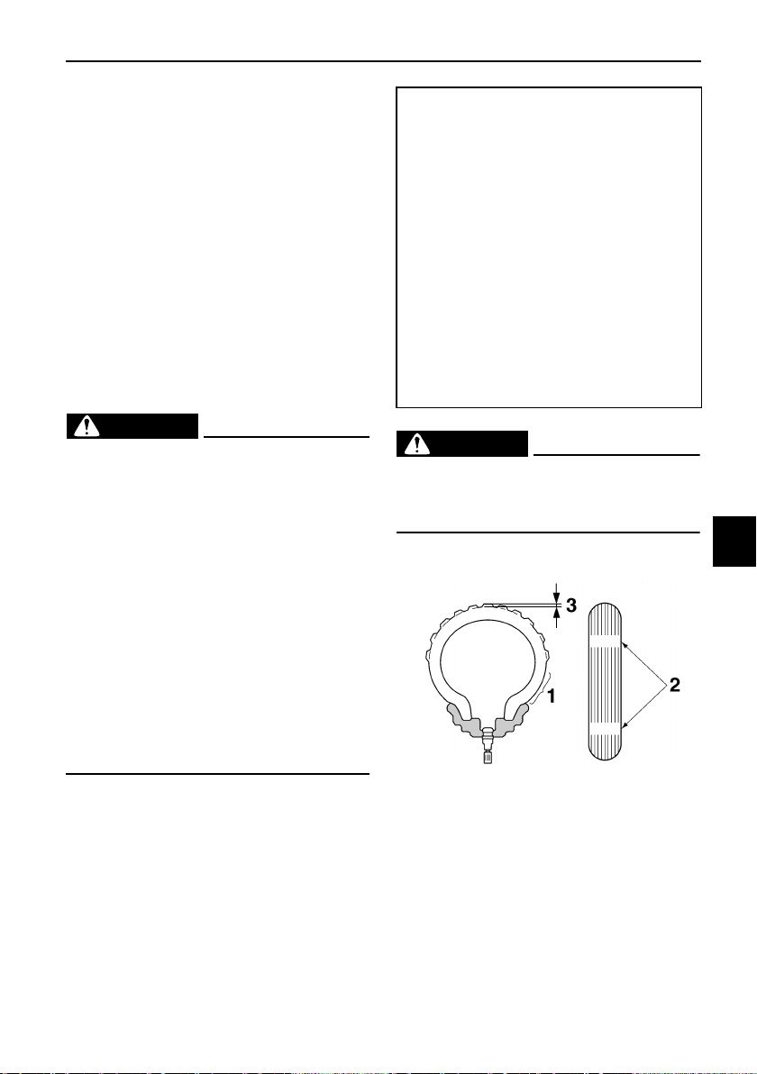
Periodic maintenance and adjustment
7-16
7
EAU64221
Tires
Tires are the only contact between the
vehicle and the road. Safety in all con-
ditions of riding depends on a relatively
small area of road contact. Therefore, it
is essential to maintain the tires in good
condition at all times and replace them
at the appropriate time with the speci-
fied tires.
Tire air pressure
The tire air pressure should be
checked and, if necessary, adjusted
before each ride.
WARNING
EWA10504
Operation of this vehicle with im-
proper tire pressure may cause se-
vere injury or death from loss of
control.
z The tire air pressure must be
checked and adjusted on cold
tires (i.e., when the temperature
of the tires equals the ambient
temperature).
z The tire air pressure must be
adjusted in accordance with the
riding speed and with the total
weight of rider, passenger, car-
go, and accessories approved
for this model.
WARNING
EWA10512
Never overload your vehicle. Opera-
tion of an overloaded vehicle could
cause an accident.
Tire inspection
The tires must be checked before each
ride. If a tire tread shows crosswise
lines (minimum tread depth), if the tire
has a nail or glass fragments in it, or if
the sidewall is cracked, contact a
Yamaha dealer immediately and have
the tire replaced.
Cold tire air pressure:
Up to 90 kg (198 lb) load:
Front:
200 kPa (2.00 kgf/cm, 29 psi)
Rear:
250 kPa (2.50 kgf/cm, 36 psi)
90 kg (198 lb) to maximum load:
Front:
200 kPa (2.00 kgf/cm, 29 psi)
Rear:
250 kPa (2.50 kgf/cm, 36 psi)
Maximum load:
Vehicle:
160 kg (353 lb)
The vehicle’s maximum load is the
combined weight of the rider, pas-
senger, cargo, and any accessories.
1. Tire sidewall
2. Tire wear indicator
3. Tire tread depth
Periodic maintenance and adjustment
7-17
7
WARNING
EWA10523
z It is dangerous to ride with a
worn-out tire. When a tire tread
begins to show crosswise lines,
have a Yamaha dealer replace
the tire immediately. Brakes,
tires and related wheel parts re-
placement should also be left to
a Yamaha dealer.
z Ride at moderate speeds after
changing a tire since the tire
surface must first be “broken
in” for it to develop its optimal
characteristics.
Tire information
This model is equipped with tubeless
tires and tire air valves.
Tires age, even if they have not been
used or have only been used occasion-
ally. Cracking of the tread and sidewall
rubber, sometimes accompanied by
carcass deformation, is an evidence of
ageing. Old and aged tires shall be
checked by tire specialists to ascertain
their suitability for further use.
WARNING
EWA10462
The front and rear tires should be of
the same make and design, other-
wise the handling characteristics of
the vehicle may be different, which
could lead to an accident.
After extensive tests, only the tires list-
ed below have been approved for this
model by Yamaha.
Minimum tire tread depth (front and
rear):
1.0 mm (0.04 in)
Front tire:
Size:
110/70R17M/C 54H
Manufacturer/model:
DUNLOP/GPR-300F
Rear tire:
Size:
140/70R17M/C 66H
Manufacturer/model:
DUNLOP/GPR-300
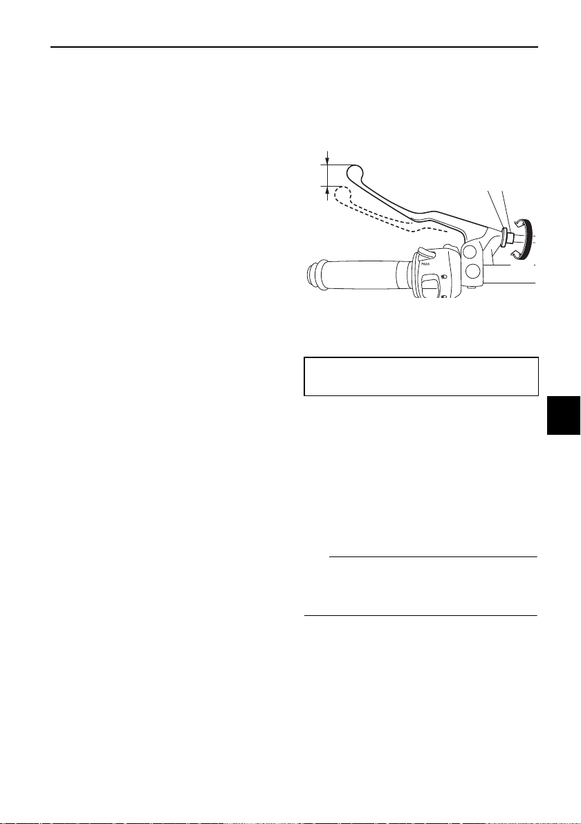
Periodic maintenance and adjustment
7-18
7
EAU21963
Cast wheels
To maximize the performance, durabil-
ity, and safe operation of your vehicle,
note the following points regarding the
specified wheels.
z The wheel rims should be
checked for cracks, bends, warp-
age or other damage before each
ride. If any damage is found, have
a Yamaha dealer replace the
wheel. Do not attempt even the
smallest repair to the wheel. A de-
formed or cracked wheel must be
replaced.
z The wheel should be balanced
whenever either the tire or wheel
has been changed or replaced. An
unbalanced wheel can result in
poor performance, adverse han-
dling characteristics, and a short-
ened tire life.
EAU33893
Adjusting the clutch lever free
play
Measure the clutch lever free play as
shown.
Periodically check the clutch lever free
play and, if necessary, adjust it as fol-
lows.
To increase the clutch lever free play,
turn the clutch lever free play adjusting
bolt at the clutch lever in direction (a).
To decrease the clutch lever free play,
turn the adjusting bolt in direction (b).
TIP
If the specified clutch lever free play
cannot be obtained as described
above, proceed as follows.
1. Fully turn the adjusting bolt at the
clutch lever in direction (a) to loos-
en the clutch cable.
2. Loosen the locknut at the crank-
case.
1. Clutch lever free play adjusting bolt
2. Locknut
3. Clutch lever free play
Clutch lever free play:
10.0–15.0 mm (0.39–0.59 in)
3
2 1
(a)
(b)
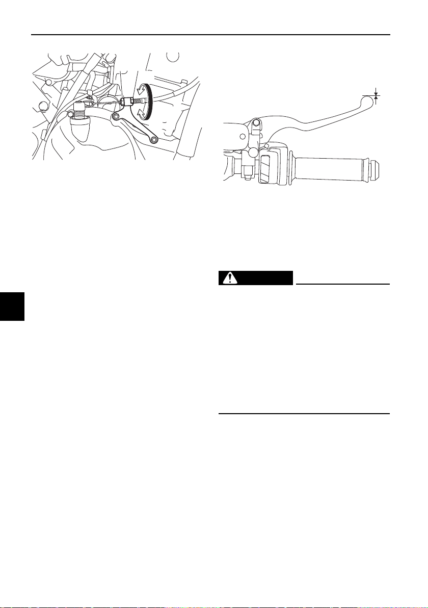
Periodic maintenance and adjustment
7-19
7
3. To increase the clutch lever free
play, turn the clutch lever free play
adjusting nut in direction (a). To
decrease the clutch lever free
play, turn the adjusting nut in di-
rection (b).
4. Tighten the locknut.
EAU37914
Checking the brake lever free
play
There should be no free play at the
brake lever end. If there is free play,
have a Yamaha dealer inspect the
brake system.
WARNING
EWA14212
A soft or spongy feeling in the brake
lever can indicate the presence of
air in the hydraulic system. If there is
air in the hydraulic system, have a
Yamaha dealer bleed the system be-
fore operating the vehicle. Air in the
hydraulic system will diminish the
braking performance, which may re-
sult in loss of control and an acci-
dent.
1. Locknut
2. Clutch lever free play adjusting nut
2
(b)
(a)
1
1. No brake lever free play
1
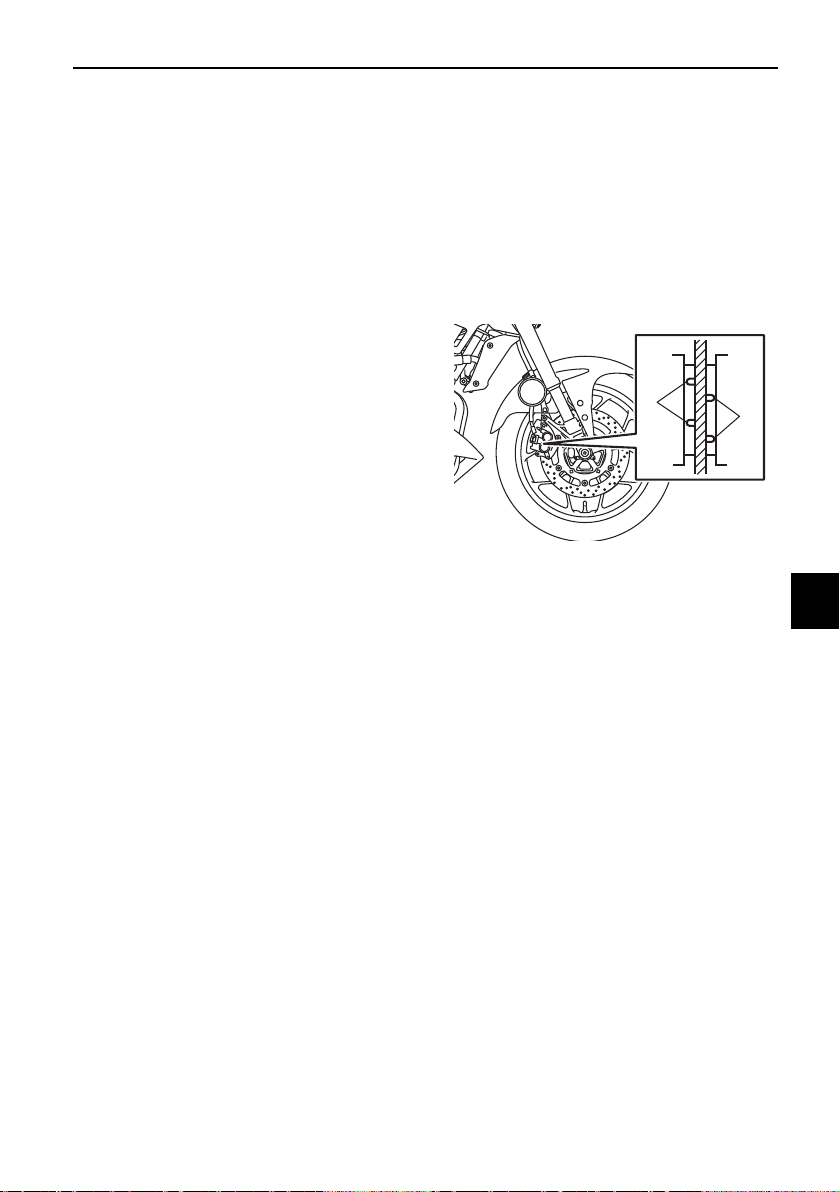
Periodic maintenance and adjustment
7-20
7
EAU36505
Brake light switches
The brake light should come on just
before braking takes effect. The brake
light is activated by switches connect-
ed to the brake lever and brake pedal.
Since the brake light switches are
components of the anti-lock brake sys-
tem, they should only be serviced by a
Yamaha dealer.
EAU22393
Checking the front and rear
brake pads
The front and rear brake pads must be
checked for wear at the intervals spec-
ified in the periodic maintenance and
lubrication chart.
EAU22433
Front brake pads
Each front brake pad is provided with
wear indicator grooves, which allow
you to check the brake pad wear with-
out having to disassemble the brake.
To check the brake pad wear, check
the wear indicator grooves. If a brake
pad has worn to the point that the wear
indicator grooves have almost disap-
peared, have a Yamaha dealer replace
the brake pads as a set.
1. Brake pad wear indicator groove
1
1
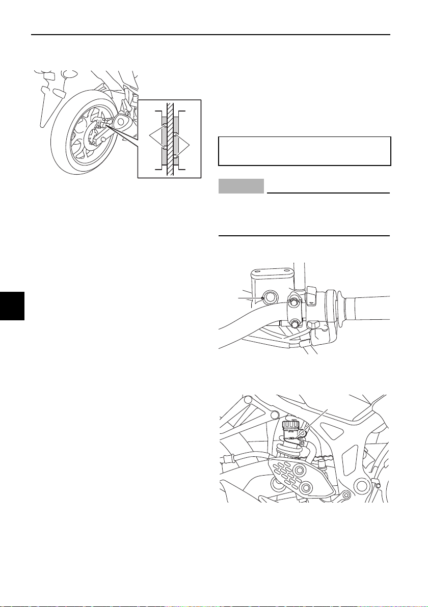
Periodic maintenance and adjustment
7-21
7
EAU36721
Rear brake pads
Each rear brake pad is provided with
wear indicator grooves, which allow
you to check the brake pad wear with-
out having to disassemble the brake.
To check the brake pad wear, check
the wear indicator grooves. If a brake
pad has worn to the point that the wear
indicator grooves have almost disap-
peared, have a Yamaha dealer replace
the brake pads as a set.
EAU22583
Checking the brake fluid level
Before riding, check that the brake fluid
is above the minimum level mark.
Check the brake fluid level with the res-
ervoir in an upright position. Replenish
the brake fluid if necessary.
NOTICE
ECA17641
Brake fluid may damage painted
surfaces or plastic parts. Always
clean up spilled fluid immediately.
Front brake
Rear brake
As the brake pads wear, it is normal for
the brake fluid level to gradually go
down.
1. Brake pad wear indicator groove
1
1
Specified brake fluid:
DOT 4
1. Minimum level mark
1. Minimum level mark
1
1
Periodic maintenance and adjustment
7-22
7
z A low brake fluid level may indi-
cate worn brake pads or brake
system leakage; therefore, be sure
to check the brake pads for wear
and the brake system for leakage.
z If the brake fluid level goes down
suddenly, have a Yamaha dealer
check the cause before further rid-
ing.
WARNING
EWA15991
Improper maintenance can result in
loss of braking ability. Observe
these precautions:
z Insufficient brake fluid may al-
low air to enter the brake sys-
tem, reducing braking
performance.
z Clean the filler cap before re-
moving. Use only DOT 4 brake
fluid from a sealed container.
z Use only the specified brake flu-
id; otherwise, the rubber seals
may deteriorate, causing leak-
age.
z Refill with the same type of
brake fluid. Adding a brake fluid
other than DOT 4 may result in a
harmful chemical reaction.
z Be careful that water does not
enter the brake fluid reservoir
when refilling. Water will signifi-
cantly lower the boiling point of
the fluid and may result in vapor
lock.
EAU22734
Changing the brake fluid
Have a Yamaha dealer change the
brake fluid every 2 years. In addition,
have the seals of the master cylinders
and brake calipers, as well as the brake
hoses replaced at the intervals listed
below or sooner if they are damaged or
leaking.
z Brake seals: every 2 years
z Brake hoses: every 4 years
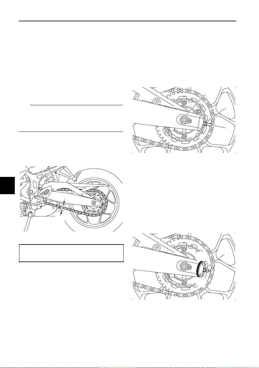
Periodic maintenance and adjustment
7-23
7
EAU22762
Drive chain slack
The drive chain slack should be
checked before each ride and adjusted
if necessary.
EAU74253
To check the drive chain slack
1. Place the motorcycle on the side-
stand.
TIP
When checking and adjusting the drive
chain slack, there should be no weight
on the motorcycle.
2. Shift the transmission into the
neutral position.
3. Measure the drive chain slack as
shown.
4. If the drive chain slack is incorrect,
adjust it as follows. NOTICE: Im-
proper drive chain slack will
overload the engine as well as
other vital parts of the motorcy-
cle and can lead to chain slip-
page or breakage. To prevent
this from occurring, keep the
drive chain slack within the
specified limits.
[ECA10572]
EAU62983
To adjust the drive chain slack
Consult a Yamaha dealer before ad-
justing the drive chain slack.
1. Remove the drive chain puller cap,
and then loosen the axle nut and
the locknut on each side of the
swingarm.
2. To tighten the drive chain, turn the
drive chain slack adjusting nut on
each side of the swingarm in di-
rection (a). To loosen the drive
chain, turn the adjusting nut on
each side of the swingarm in di-
rection (b), and then push the rear
wheel forward.
1. Drive chain slack
Drive chain slack:
35.0–45.0 mm (1.38–1.77 in)
1
1. Locknut
2. Drive chain puller cap
1. Drive chain slack adjusting nut
2
3
1
1
(a)
(b)
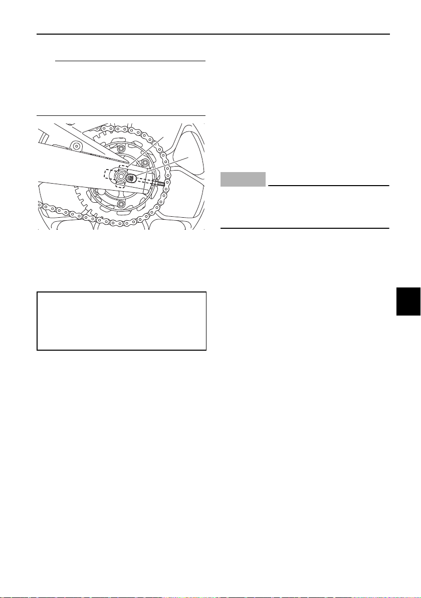
Periodic maintenance and adjustment
7-24
7
TIP
Using the alignment marks on each
side of the swingarm, make sure that
both drive chain pullers are in the same
position for proper wheel alignment.
3. Tighten the axle nut, then the lock-
nuts to their specified torques.
4. Make sure that the drive chain
pullers are in the same position,
the drive chain slack is correct,
and the drive chain moves
smoothly.
5. Install the drive chain puller caps.
EAU23026
Cleaning and lubricating the
drive chain
The drive chain must be cleaned and
lubricated at the intervals specified in
the periodic maintenance and lubrica-
tion chart, otherwise it will quickly wear
out, especially when riding in dusty or
wet areas. Service the drive chain as
follows.
NOTICE
ECA10584
The drive chain must be lubricated
after washing the motorcycle, riding
in the rain or riding in wet areas.
1. Clean the drive chain with kero-
sene and a small soft brush.
NOTICE: To prevent damaging
the O-rings, do not clean the
drive chain with steam cleaners,
high-pressure washers or inap-
propriate solvents.
[ECA11122]
2. Wipe the drive chain dry.
3. Thoroughly lubricate the drive
chain with a special O-ring chain
lubricant. NOTICE: Do not use
engine oil or any other lubri-
cants for the drive chain, as they
may contain substances that
could damage the O-rings.
[ECA11112]
1. Alignment marks
2. Drive chain puller
Tightening torques:
Axle nut:
57 N·m (5.7 kgf·m, 42 lb·ft)
Locknut:
16 N·m (1.6 kgf·m, 12 lb·ft)
1
2
Periodic maintenance and adjustment
7-25
7
EAU23098
Checking and lubricating the
cables
The operation of all control cables and
the condition of the cables should be
checked before each ride, and the ca-
bles and cable ends should be lubri-
cated if necessary. If a cable is
damaged or does not move smoothly,
have a Yamaha dealer check or re-
place it. WARNING! Damage to the
outer housing of cables may result
in internal rusting and cause inter-
ference with cable movement. Re-
place damaged cables as soon as
possible to prevent unsafe condi-
tions.
[EWA10712]
EAU49921
Checking and lubricating the
throttle grip and cable
The operation of the throttle grip
should be checked before each ride. In
addition, the cable should be lubricat-
ed by a Yamaha dealer at the intervals
specified in the periodic maintenance
chart.
Recommended lubricant:
Yamaha cable lubricant or other
suitable cable lubricant
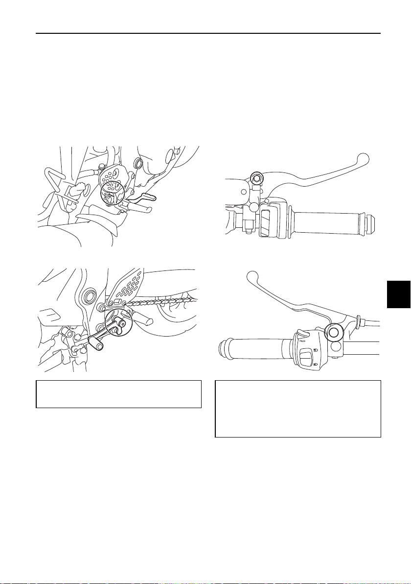
Periodic maintenance and adjustment
7-26
7
EAU44276
Checking and lubricating the
brake and shift pedals
The operation of the brake and shift
pedals should be checked before each
ride, and the pedal pivots should be lu-
bricated if necessary.
Brake pedal
Shift pedal
EAU23144
Checking and lubricating the
brake and clutch levers
The operation of the brake and clutch
levers should be checked before each
ride, and the lever pivots should be lu-
bricated if necessary.
Brake lever
Clutch lever
Recommended lubricant:
Lithium-soap-based grease
Recommended lubricants:
Brake lever:
Silicone grease
Clutch lever:
Lithium-soap-based grease

Periodic maintenance and adjustment
7-27
7
EAU23203
Checking and lubricating the
sidestand
The operation of the sidestand should
be checked before each ride, and the
sidestand pivot and metal-to-metal
contact surfaces should be lubricated
if necessary.
WARNING
EWA10732
If the sidestand does not move up
and down smoothly, have a Yamaha
dealer check or repair it. Otherwise,
the sidestand could contact the
ground and distract the operator, re-
sulting in a possible loss of control.
EAUM1653
Lubricating the swingarm piv-
ots
The swingarm pivots must be lubricat-
ed by a Yamaha dealer at the intervals
specified in the periodic maintenance
and lubrication chart.
Recommended lubricant:
Lithium-soap-based grease
Recommended lubricant:
Lithium-soap-based grease
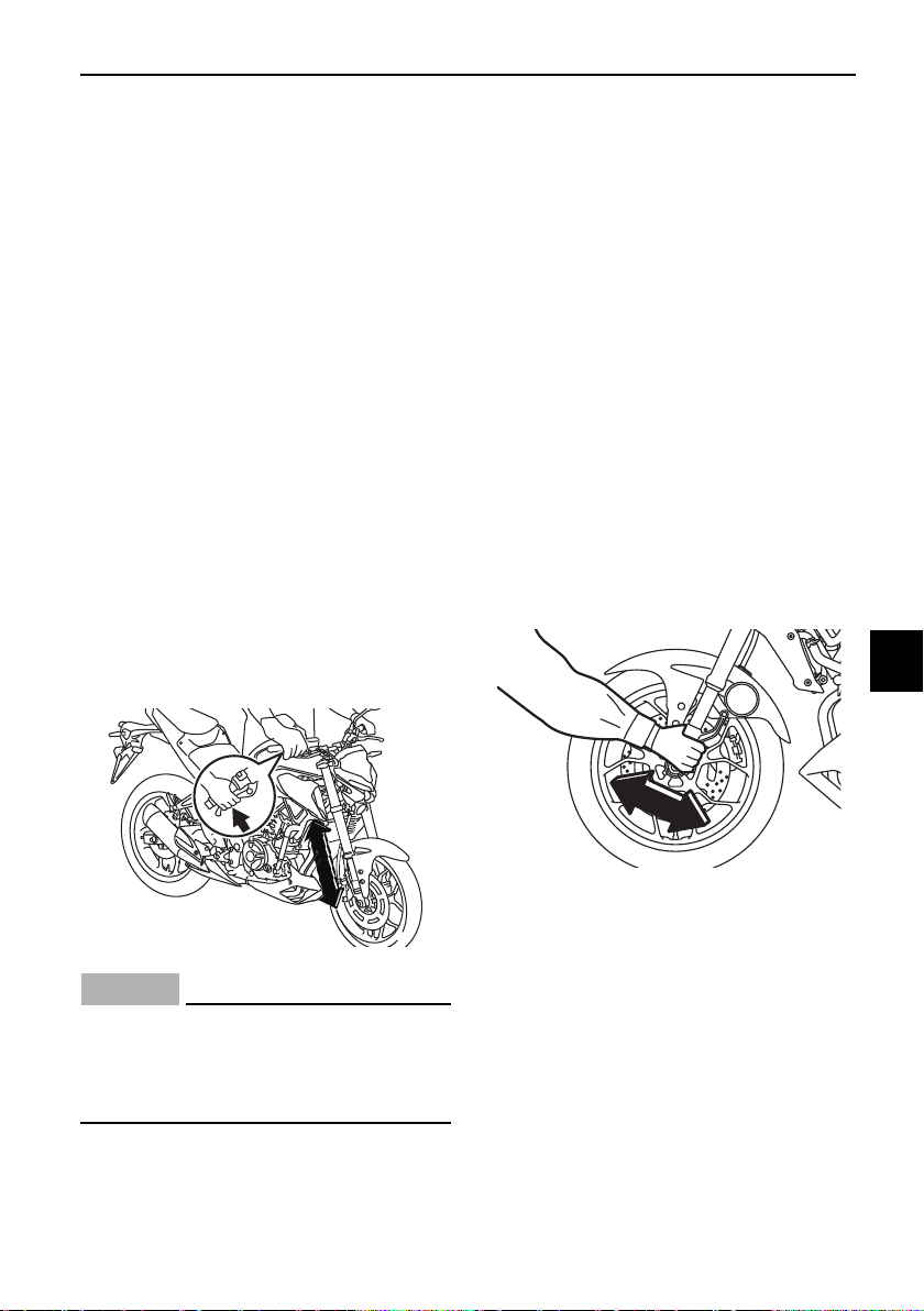
Periodic maintenance and adjustment
7-28
7
EAU23273
Checking the front fork
The condition and operation of the
front fork must be checked as follows
at the intervals specified in the periodic
maintenance and lubrication chart.
To check the condition
Check the inner tubes for scratches,
damage and excessive oil leakage.
To check the operation
1. Place the vehicle on a level sur-
face and hold it in an upright posi-
tion. WARNING! To avoid injury,
securely support the vehicle so
there is no danger of it falling
over.
[EWA10752]
2. While applying the front brake,
push down hard on the handle-
bars several times to check if the
front fork compresses and re-
bounds smoothly.
NOTICE
ECA10591
If any damage is found or the front
fork does not operate smoothly,
have a Yamaha dealer check or re-
pair it.
EAU23285
Checking the steering
Worn or loose steering bearings may
cause danger. Therefore, the operation
of the steering must be checked as fol-
lows at the intervals specified in the
periodic maintenance and lubrication
chart.
1. Raise the front wheel off the
ground. (See page 7-34.)
WARNING! To avoid injury, se-
curely support the vehicle so
there is no danger of it falling
over.
[EWA10752]
2. Hold the lower ends of the front
fork legs and try to move them for-
ward and backward. If any free
play can be felt, have a Yamaha
dealer check or repair the steer-
ing.
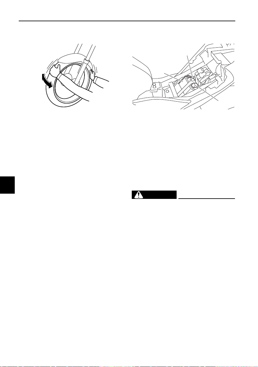
Periodic maintenance and adjustment
7-29
7
EAU23292
Checking the wheel bearings
The front and rear wheel bearings must
be checked at the intervals specified in
the periodic maintenance and lubrica-
tion chart. If there is play in the wheel
hub or if the wheel does not turn
smoothly, have a Yamaha dealer
check the wheel bearings.
EAU50583
Battery
The battery is located under the rider
seat. It is a VRLA (valve-regulated lead-
acid) battery. There is no need to check
the electrolyte or to add distilled water.
However, the battery lead connections
need to be checked, and tightened if
necessary.
WARNING
EWA10761
z Electrolyte is poisonous and
dangerous since it contains sul-
furic acid, which causes severe
burns. Avoid any contact with
skin, eyes or clothing and al-
ways shield your eyes when
working near batteries. In case
of contact, administer the fol-
lowing FIRST AID.
• EXTERNAL: Flush with plenty
of water.
• INTERNAL: Drink large quan-
tities of water or milk and im-
mediately call a physician.
• EYES: Flush with water for 15
minutes and seek prompt
medical attention.
1. Battery
2. Negative battery lead (black)
3. Positive battery lead (red)
1
2
3
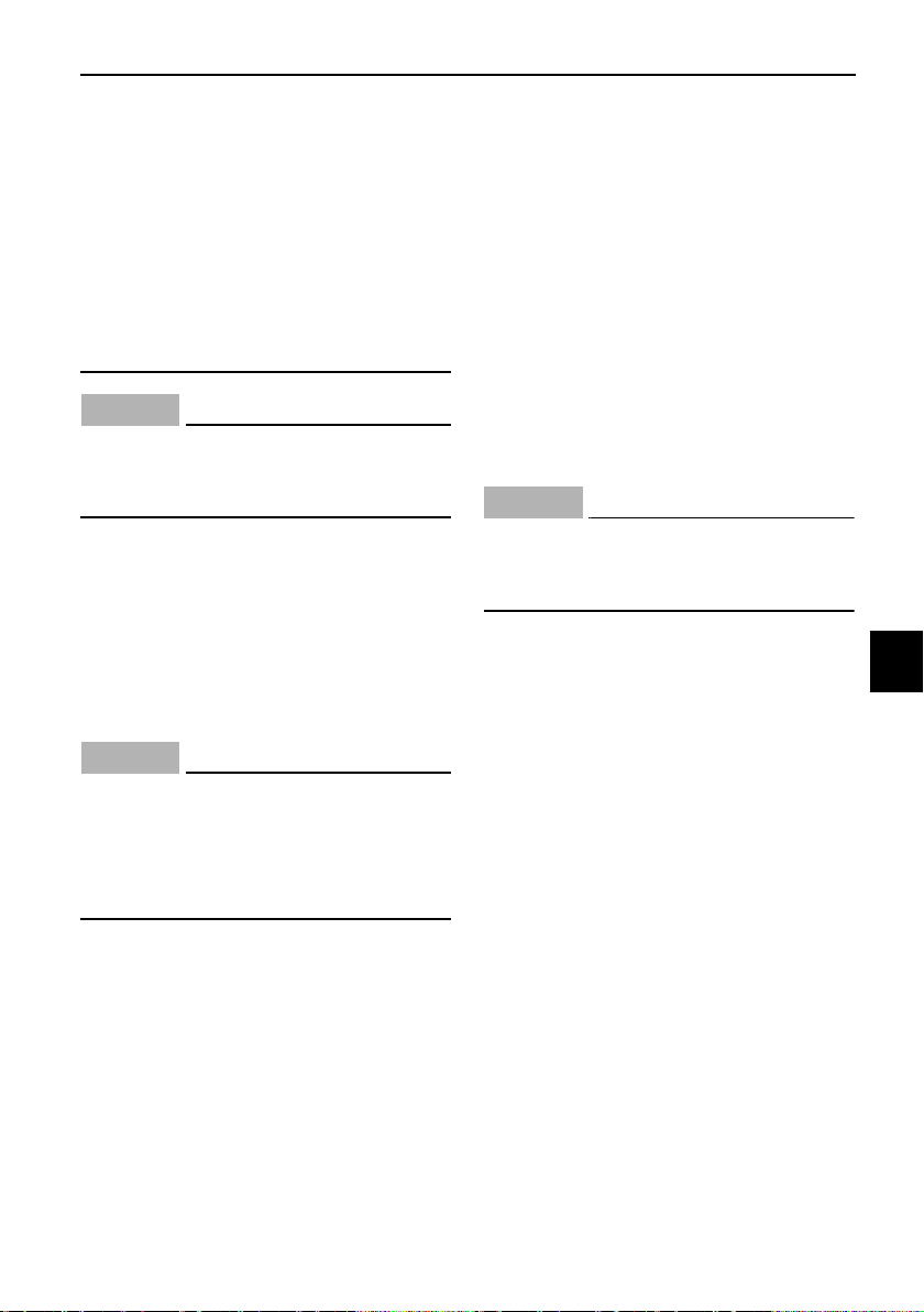
Periodic maintenance and adjustment
7-30
7
z Batteries produce explosive hy-
drogen gas. Therefore, keep
sparks, flames, cigarettes, etc.,
away from the battery and pro-
vide sufficient ventilation when
charging it in an enclosed
space.
z KEEP THIS AND ALL BATTER-
IES OUT OF THE REACH OF
CHILDREN.
NOTICE
ECA10621
Never attempt to remove the battery
cell seals, as this would permanently
damage the battery.
To charge the battery
Have your Yamaha dealer charge the
battery if it seems to have discharged.
Keep in mind that the battery tends to
discharge more quickly if the vehicle is
equipped with optional electrical ac-
cessories.
NOTICE
ECA16522
To charge a VRLA (Valve Regulated
Lead Acid) battery, a special (con-
stant-voltage) battery charger is re-
quired. Using a conventional battery
charger will damage the battery.
To store the battery
1. If the vehicle will not be used for
more than one month, remove the
battery, fully charge it, and then
place it in a cool, dry place.
NOTICE: When removing the
battery, be sure to turn the main
switch off, then disconnect the
negative lead before discon-
necting the positive lead.
[ECA16304]
2. If the battery will be stored for
more than two months, check it at
least once a month and fully
charge it if necessary.
3. Fully charge the battery before in-
stallation. NOTICE: When install-
ing the battery, be sure to turn
the main switch off, then con-
nect the positive lead before
connecting the negative lead.
[ECA16842]
4. After installation, make sure that
the battery leads are properly con-
nected to the battery terminals.
NOTICE
ECA16531
Always keep the battery charged.
Storing a discharged battery can
cause permanent battery damage.
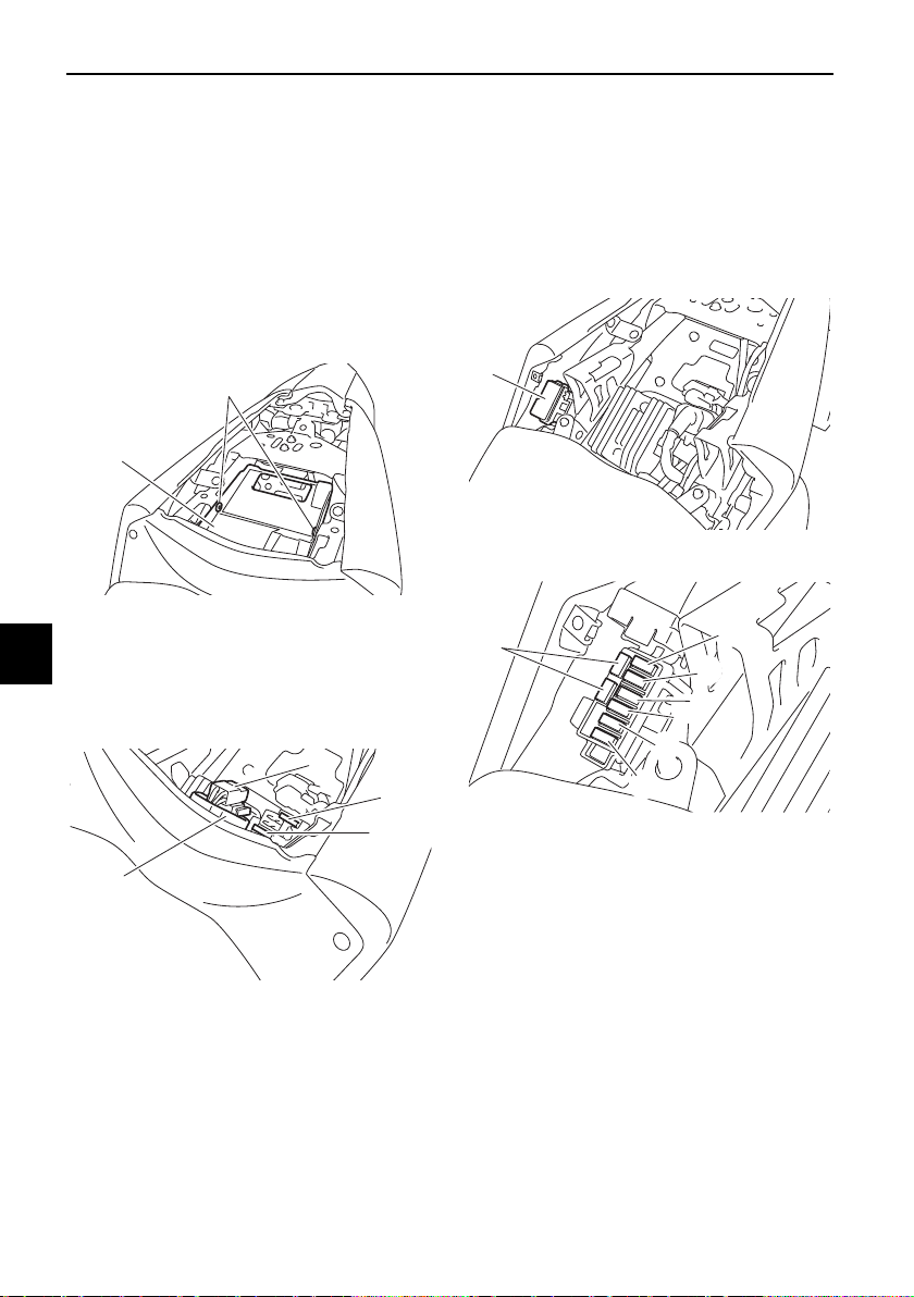
Periodic maintenance and adjustment
7-31
7
EAUN0824
Replacing the fuses
The main fuse is located under the
passenger seat.
To access the main fuse, proceed as
follows.
1. Remove the passenger seat. (See
page 4-18.)
2. Remove the tray by removing the
quick fasteners.
3. Pull back the starter relay cover,
and then disconnect the starter re-
lay coupler as shown.
4. Connect the starter relay coupler,
and then slide the cover to its orig-
inal position.
5. Place the tray in its original posi-
tion, and then install the quick fas-
teners.
6. Install the passenger seat.
Fuse box 1 is located behind the center
cover. (See page 4-18.)
Fuse box 1
Fuse box 2 is located under the rider
seat. (See page 4-18.)
1. Quick fastener
2. Tray
1. Starter relay cover
2. Starter relay coupler
3. Main fuse
4. Spare main fuse
2
1
1
2
3
4
1. Fuse box 1
1. Ignition fuse
2. Signaling system fuse
3. ABS control unit fuse
4. Headlight fuse
5. Backup fuse (for clock)
6. Radiator fan motor fuse
7. Spare fuse
1
7
1
2
3
5
6
4
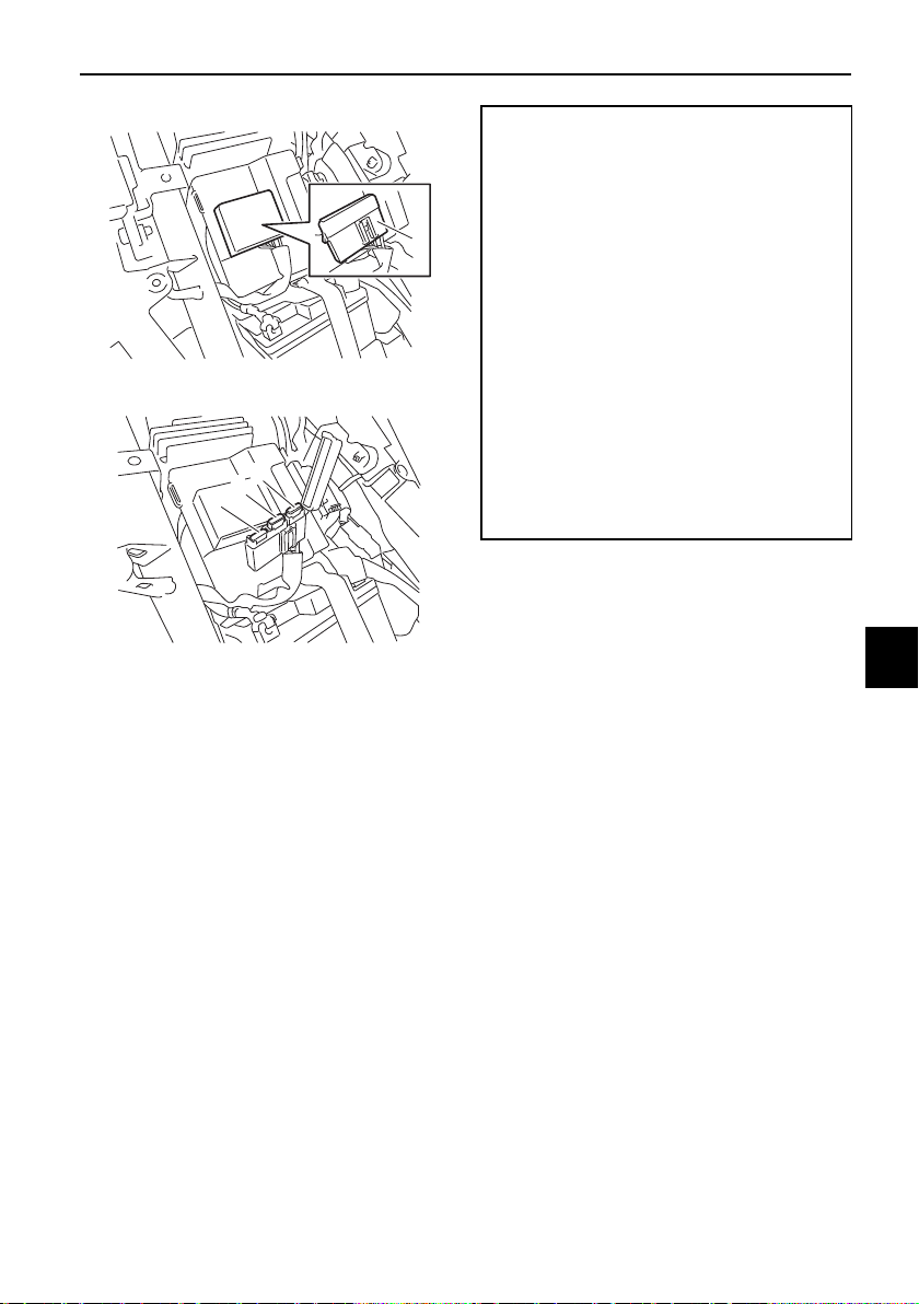
Periodic maintenance and adjustment
7-32
7
Fuse box 2
If a fuse is blown, replace it as follows.
1. Turn the main switch off and turn
off the electrical circuit in ques-
tion.
2. Remove the blown fuse, and then
install a new fuse of the specified
amperage. WARNING! Do not
use a fuse of a higher amperage
rating than recommended to
avoid causing extensive dam-
age to the electrical system and
possibly a fire.
[EWA15132]
3. Turn the main switch on and turn
on the electrical circuit in question
to check if the device operates.
4. If the fuse immediately blows
again, have a Yamaha dealer
check the electrical system.
1. Fuse box 2
1. Spare fuse
2. ABS solenoid fuse
3. ABS motor fuse
1
1
2
3
Specified fuses:
Main fuse:
30.0 A
Headlight fuse:
7.5 A
Signaling system fuse:
15.0 A
Ignition fuse:
15.0 A
Radiator fan motor fuse:
7.5 A
ABS motor fuse:
30.0 A
ABS solenoid fuse:
15.0 A
ABS control unit fuse:
7.5 A
Backup fuse:
7.5 A
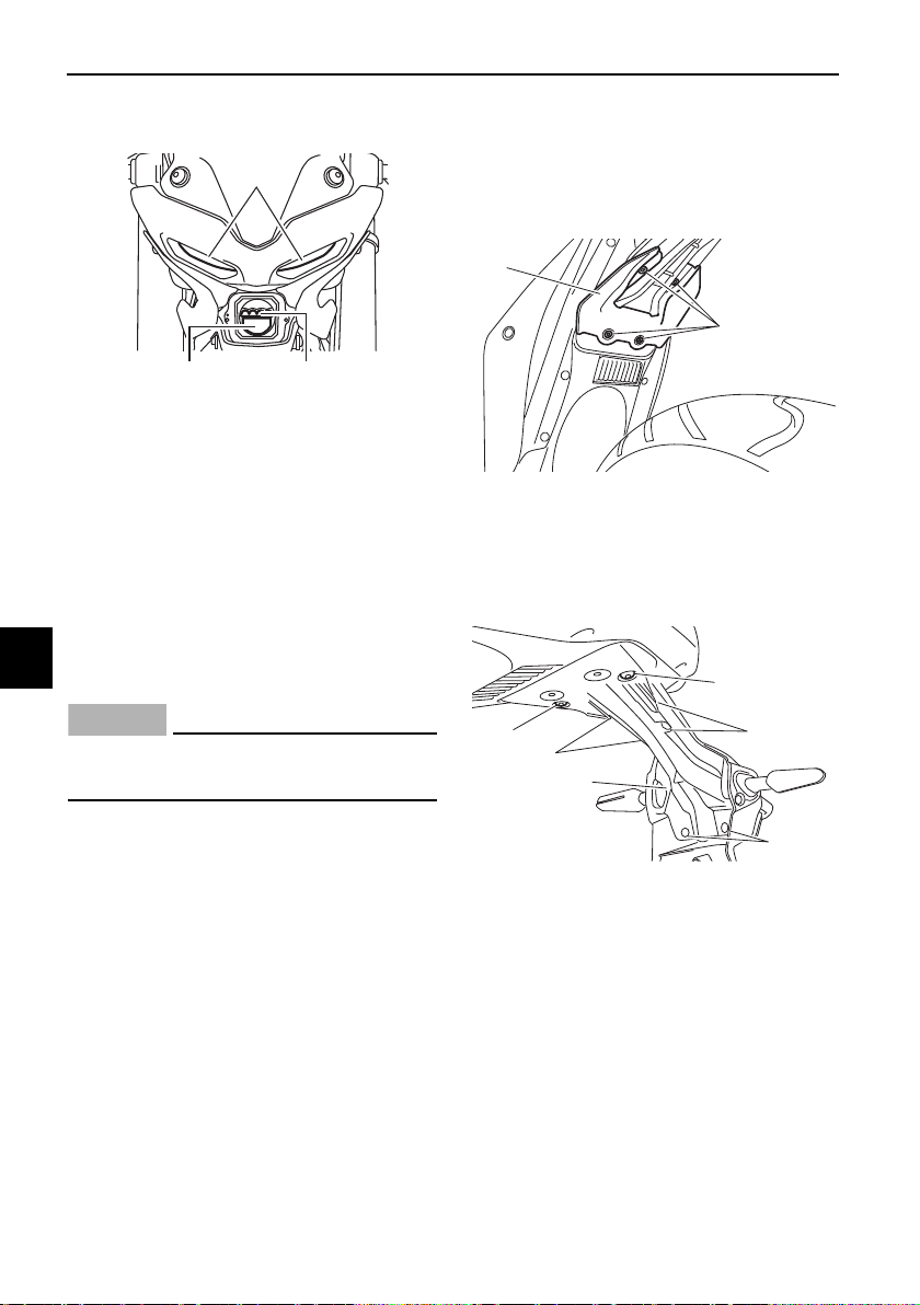
Periodic maintenance and adjustment
7-33
7
EAU80380
Vehicle lights
Except for the license plate light bulb,
this model’s lights are all LED.
If an LED light does not come on,
check the fuses and then have a
Yamaha dealer check the vehicle. If the
license plate light does not come on,
check and replace the bulb. (See page
7-33.)
NOTICE
ECA16581
Do not affix any type of tinted film or
stickers to the headlight lens.
EAU62670
Replacing the license plate
light bulb
1. Remove the mudguard by remov-
ing the quick fasteners.
2. Remove the rear fender lower
panel by removing the bolts and
screws.
3. Remove the license plate light
bulb socket (together with the
bulb) by pulling it out.
4. Remove the burnt-out bulb by
pulling it out.
1. Headlight (high beam)
2. Headlight (low beam)
3. Auxiliary light
3
12
1. Mudguard
2. Quick fastener
1. Bolt
2. Screw
3. Rear fender lower panel
1
2
3
2
1
2
2
1
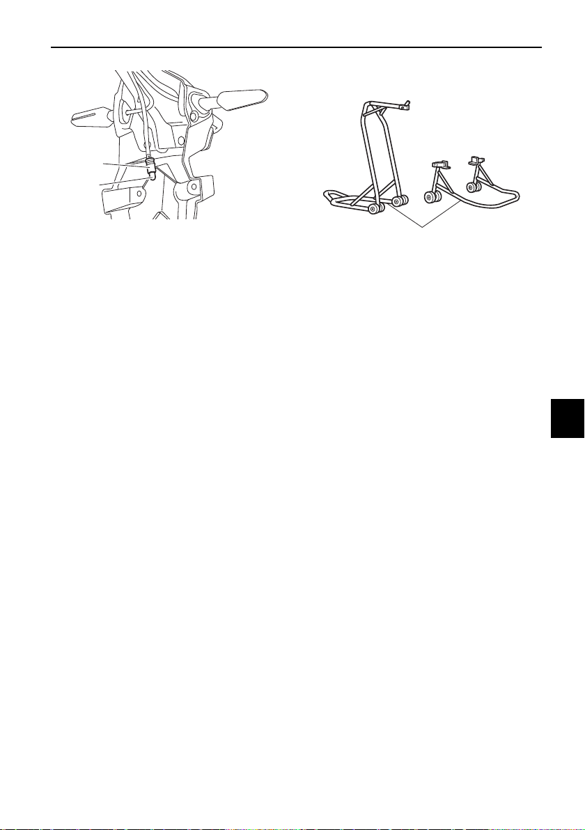
Periodic maintenance and adjustment
7-34
7
5. Insert a new bulb into the socket.
6. Install the socket (together with
the bulb) by pushing it in.
7. Install the rear fender lower panel
by installing the bolts and screws.
8. Install the mudguard by installing
the quick fasteners.
EAU67131
Supporting the motorcycle
Since this model is not equipped with a
centerstand, use maintenance stands
when removing the front or rear wheel
or when performing other maintenance
that requires the motorcycle to stand
up right.
Check that the motorcycle is in a stable
and level position before starting any
maintenance.
1. License plate light bulb
2. License plate light bulb socket
2
1
1. Maintenance stand (example)
1
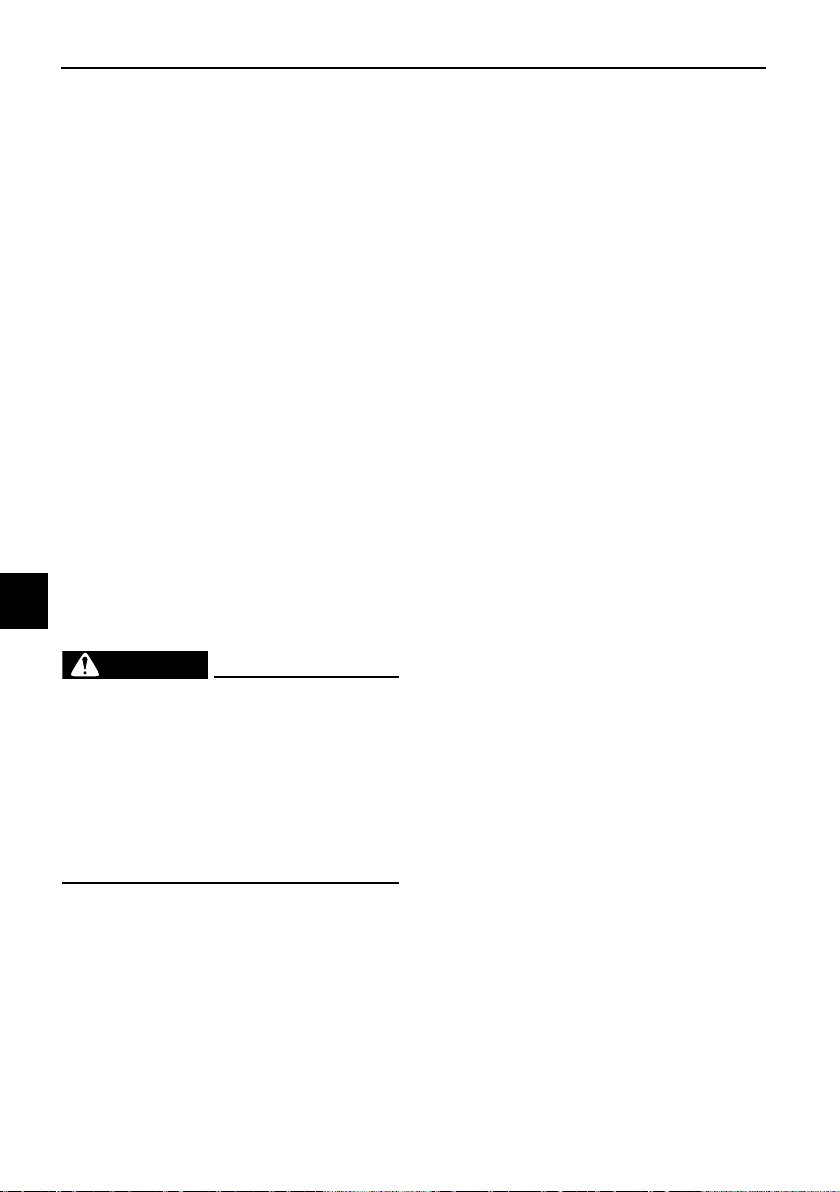
Periodic maintenance and adjustment
7-35
7
EAU25872
Troubleshooting
Although Yamaha motorcycles receive
a thorough inspection before shipment
from the factory, trouble may occur
during operation. Any problem in the
fuel, compression, or ignition systems,
for example, can cause poor starting
and loss of power.
The following troubleshooting charts
represent quick and easy procedures
for checking these vital systems your-
self. However, should your motorcycle
require any repair, take it to a Yamaha
dealer, whose skilled technicians have
the necessary tools, experience, and
know-how to service the motorcycle
properly.
Use only genuine Yamaha replace-
ment parts. Imitation parts may look
like Yamaha parts, but they are often
inferior, have a shorter service life and
can lead to expensive repair bills.
WARNING
EWA15142
When checking the fuel system, do
not smoke, and make sure there are
no open flames or sparks in the ar-
ea, including pilot lights from water
heaters or furnaces. Gasoline or
gasoline vapors can ignite or ex-
plode, causing severe injury or prop-
erty damage.
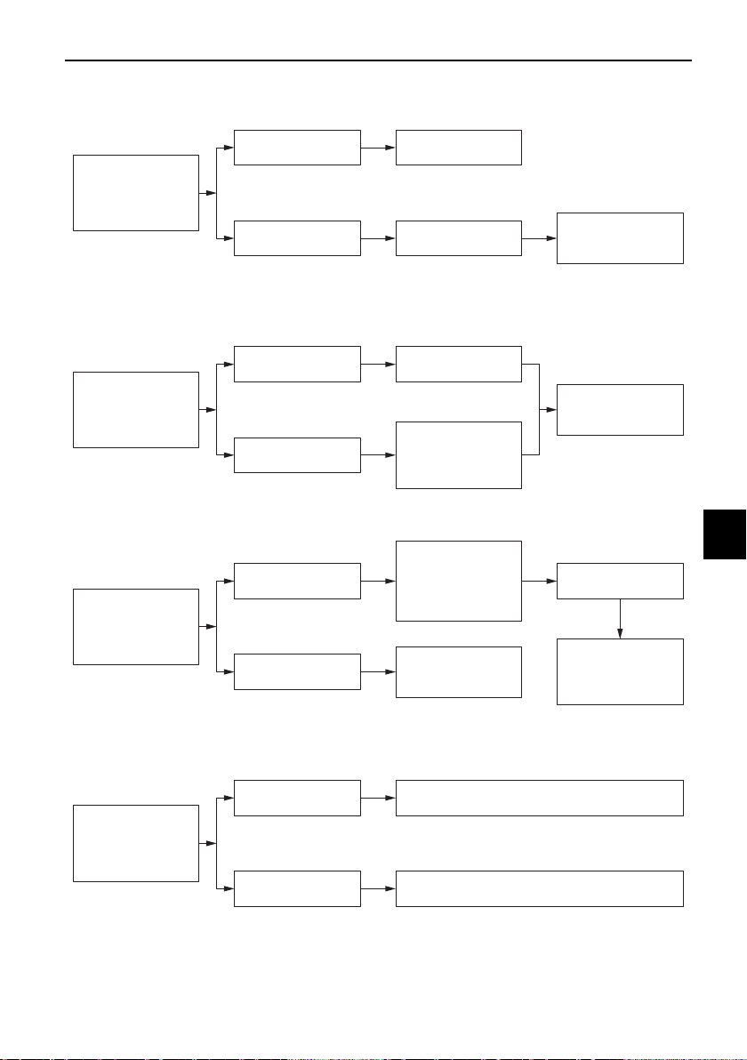
Periodic maintenance and adjustment
7-36
7
EAU86390
Troubleshooting chart
1. Fuel
There is enough fuel.
There is no fuel.
Check the battery.
Supply fuel.
The engine turns over
quickly.
The engine turns over
slowly.
Try starting the
engine.
The engine does not
start.
Check the battery.
Wipe off with a dry
cloth and correct the
spark plug gap, or
replace the spark
plug(s).
Check the battery
lead connections,
and charge the
battery if necessary.
2. Battery
The battery is good.
The engine does not
start.
Check the ignition.
3. Ignition
Wet
Dry
There is compression.
There is no
compression.
The engine does not start.
Have a Yamaha dealer check the vehicle.
Have a Yamaha dealer check the vehicle.
The engine does not
start.
Check the
compression.
Have a Yamaha
dealer check the
vehicle.
Remove the spark
plug and check
the electrodes.
Operate the electric
starter.
Try starting the
engine.
Check the fuel level
in the fuel tank.
4. Compression
Periodic maintenance and adjustment
7-37
7
EAU86430
Engine overheating
WARNING
EWAT1041
z Do not remove the radiator cap when the engine and radiator are hot.
Scalding hot fluid and steam may be blown out under pressure, which
could cause serious injury. Be sure to wait until the engine has cooled.
z Place a thick rag, like a towel, over the radiator cap, and then slowly ro-
tate the cap counterclockwise to the detent to allow any residual pres-
sure to escape. When the hissing sound has stopped, press down on the
cap while turning it counterclockwise, and then remove the cap.
TIP
If coolant is not available, tap water can be temporarily used instead, provided
that it is changed to the recommended coolant as soon as possible.
Wait until the engine
has cooled.
Check the coolant
level in the reservoir
and radiator.
Add coolant.
(See TIP.)
The coolant level is
OK.
There is no leakage.
There is leakage.
The coolant level is
low.
Check the cooling
system for leakage.
Have a Yamaha
dealer check and
repair the cooling
system.
Start the engine. If the engine overheats again,
have a Yamaha dealer check and repair the cooling
system.
Motorcycle care and storage
8-1
8
EAU37834
Matte color caution
NOTICE
ECA15193
Some models are equipped with
matte colored finished parts. Be
sure to consult a Yamaha dealer for
advice on what products to use be-
fore cleaning the vehicle. Using a
brush, harsh chemical products or
cleaning compounds when cleaning
these parts will scratch or damage
their surface. Wax also should not
be applied to any matte colored fin-
ished parts.
EAU83911
Care
Frequent, thorough cleaning of the ve-
hicle will not only enhance its appear-
ance but also will improve its general
performance and extend the useful life
of many components. Washing, clean-
ing, and polishing will also give you a
chance to inspect the condition of the
vehicle more frequently. Be sure to
wash the vehicle after riding in the rain
or near the sea, because salt is corro-
sive to metals.
TIP
z The roads of heavy snowfall areas
may be sprayed with salt as a de-
icing method. This salt can stay on
the roads well into spring, so be
sure to wash the underside and
chassis parts after riding in such
areas.
z Genuine Yamaha care and main-
tenance products are sold under
the YAMALUBE brand.
z See your Yamaha dealer for addi-
tional cleaning tips.
NOTICE
ECA26280
Improper cleaning can cause cos-
metic and mechanical damage. Do
not use:
z high-pressure washers or
steam-jet cleaners. Excessive
water pressure may cause wa-
ter seepage and deterioration of
wheel bearings, brakes, trans-
mission seals and electrical de-
vices. Avoid high-pressure
detergent applications such as
those available in coin-operated
car washers.

Motorcycle care and storage
8-2
8
z harsh chemicals, including
strong acidic wheel cleaners,
especially on spoke or magne-
sium wheels.
z harsh chemicals, abrasive
cleaning compounds, or wax on
matte-finished parts. Brushes
can scratch and damage the
matte-finish, use soft sponge or
towel only.
z towels, sponges, or brushes
contaminated with abrasive
cleaning products or strong
chemicals such as, solvents,
gasoline, rust removers, brake
fluid, or antifreeze, etc.
Before washing
1. Park the vehicle out of direct sun-
light and allow it to cool. This will
help avoid water spots.
2. Make sure all caps, covers, elec-
trical couplers and connectors are
tightly installed.
3. Cover the muffler end with a plas-
tic bag and a strong rubber band.
4. Pre-soak stubborn stains like in-
sects or bird droppings with a wet
towel for a few minutes.
5. Remove road grime and oil stains
with a biodegradable degreaser
(YAMACLEAN Pro-Wash Spray)
and a plastic-bristle brush or
sponge. NOTICE: Do not use
degreasing agent on areas re-
quiring lubrication such as
seals, gaskets, and wheel axles.
Follow product instructions.
[ECA26290]
Washing
1. Rinse off any degreaser and spray
down the vehicle with a garden
hose. Use only enough pressure
to do the job. Avoid spraying wa-
ter directly into the muffler, instru-
ment panel, air inlet, or other inner
areas such as underseat storage
compartments.
2. Wash the vehicle with a quality au-
tomotive-type detergent
(YAMALUBE Wash & Wax) mixed
with cool water and a soft, clean
towel or sponge. Use an old tooth-
brush or plastic-bristle brush for
hard-to-reach places. NOTICE:
Use cold water if the vehicle has
been exposed to salt. Warm wa-
ter will increase salt’s corrosive
properties.
[ECA26301]
3. For windshield-equipped vehicles:
Clean the windshield with a soft
towel or sponge dampened with
water and a pH neutral detergent.
If necessary, use a high-quality
windshield cleaner (YAMACLEAN
Glass Cleaner) or windshield pol-
ish. NOTICE: Never use any
strong chemicals to clean the
windshield. Additionally, some
cleaning compounds for plastic
may scratch the windshield, so
be sure to test all cleaning prod-
ucts before general application.
[ECA26310]
4. Rinse off thoroughly with clean
water. Be sure to remove all deter-
gent residues, as they can be
harmful to plastic parts.
Motorcycle care and storage
8-3
8
After washing
1. Dry the vehicle with a chamois or
absorbent towel, preferably mi-
crofiber terrycloth.
2. For drive chain-equipped models,
dry and then lubricate it to prevent
rust.
3. Use a chrome polish to shine
chrome, aluminum, and stainless
steel parts. Often the thermally in-
duced discoloring of stainless
steel exhaust systems can be re-
moved through polishing.
4. Apply a corrosion protection spray
(YAMALUBE Silicone Protectant &
Lubricant) on all metal parts in-
cluding chrome or nickel-plated
surfaces. WARNING! Do not ap-
ply silicone or oil spray to seats,
hand grips, rubber foot pegs or
tire treads. Otherwise these
parts will become slippery,
which could cause loss of con-
trol. Thoroughly clean the sur-
faces of these parts before
operating the vehicle.
[EWA20650]
5. Treat rubber, vinyl, and unpainted
plastic parts with a suitable care
product (YAMACLEAN Vinyl
Dressing).
6. Touch up minor paint damage
caused by stones, etc.
7. Wax all painted surfaces using a
non-abrasive wax or use a detail
spray for motorcycles
(YAMALUBE Spray Polish & In-
stant Detailer).
8. When finished cleaning, start the
engine and let it idle for several
minutes to help dry any remaining
moisture.
9. If the headlight lens has fogged
up, start the engine and turn on
the headlight to help remove the
moisture.
10. Let the vehicle dry completely be-
fore storing or covering it.
NOTICE
ECA26320
z Do not apply wax to rubber or
unpainted plastic parts.
z Do not use abrasive polishing
compounds as they will wear
away the paint.
z Apply sprays and wax sparingly.
Wipe off excess afterwards.
WARNING
EWA20660
Contaminants left on the brakes or
tires can cause loss of control.
z Make sure there is no lubricant
or wax on the brakes or tires.
z If necessary, wash the tires with
warm water and a mild deter-
gent.
z If necessary, clean the brake
discs and pads with brake
cleaner or acetone.
z Before riding at higher speeds,
test the vehicle’s braking per-
formance and cornering behav-
ior.
Motorcycle care and storage
8-4
8
EAU84141
Storage
Always store the vehicle in a cool, dry
place. If necessary, protect it against
dust with a porous cover. Be sure the
engine and the exhaust system are
cool before covering the vehicle. If the
vehicle often sits for weeks at a time
between uses, the use of a quality fuel
stabilizer (Fuel Med RX) is recommend-
ed after each fill-up.
NOTICE
ECA21170
z Storing the vehicle in a poorly
ventilated room or covering it
with a tarp, while it is still wet,
will allow water and humidity to
seep in and cause rust.
z To prevent corrosion, avoid
damp cellars, stables (because
of the presence of ammonia)
and areas where strong chemi-
cals are stored.
Long term storage
Before storing the vehicle long term (60
days or more):
1. Make all necessary repairs and
perform any outstanding mainte-
nance.
2. Follow all instructions in the Care
section of this chapter.
3. Fill up the fuel tank, adding fuel
stabilizer according to product in-
structions. Run the engine for 5
minutes to distribute treated fuel
through the fuel system.
4. For vehicles equipped with a fuel
cock: Turn the fuel cock lever to
the off position.
5. For vehicles with a carburetor: To
prevent fuel deposits from build-
ing up, drain the fuel in the carbu-
retor float chamber into a clean
container. Retighten the drain bolt
and pour the fuel back into the fuel
tank.
6. Use a quality engine fogging oil
(YAMALUBE Stor-Rite Engine
Fogging Oil) according to product
instructions to protect internal en-
gine components from corrosion.
If engine fogging oil is not avail-
able, perform the following steps
for each cylinder:
a. Remove the spark plug cap
and spark plug.
b. Pour a teaspoonful of engine
oil into the spark plug bore.
c. Install the spark plug cap onto
the spark plug, and then place
the spark plug on the cylinder
head so that the electrodes are
grounded. (This will limit spark-
ing during the next step.)
d. Turn the engine over several
times with the starter. (This will
coat the cylinder wall with oil.)
WARNING! To prevent dam-
age or injury from sparking,
make sure to ground the
spark plug electrodes while
turning the engine over.
[EWA10952]
e. Remove the spark plug cap
from the spark plug, and then
install the spark plug and the
spark plug cap.
7. Lubricate all control cables, piv-
ots, levers and pedals, as well as
the sidestand and centerstand (if
equipped).

Motorcycle care and storage
8-5
8
8. Check and correct the tire air
pressure, and then lift the vehicle
so that all wheels are off the
ground. Otherwise, turn the
wheels a little once a month in or-
der to prevent the tires from be-
coming degraded in one spot.
9. Cover the muffler outlet with a
plastic bag to prevent moisture
from entering it.
10. Remove the battery and fully
charge it, or attach a maintenance
charger to keep the battery opti-
mally charged. NOTICE: Confirm
that the battery and its charger
are compatible. Do not charge a
VRLA battery with a convention-
al charger.
[ECA26330]
TIP
z If the battery will be removed,
charge it once a month and store
it in a temperate location between
32-90 °F (0-30 °C).
z See page 7-29 for more informa-
tion on charging and storing the
battery.
Specifications
9-1
9
Dimensions:
Overall length:
2090 mm (82.3 in)
Overall width:
755 mm (29.7 in)
Overall height:
1070 mm (42.1 in)
Seat height:
780 mm (30.7 in)
Wheelbase:
1380 mm (54.3 in)
Ground clearance:
160 mm (6.30 in)
Minimum turning radius:
2.9 m (9.51 ft)
Weight:
Curb weight:
169 kg (373 lb)
Engine:
Combustion cycle:
4-stroke
Cooling system:
Liquid cooled
Valve train:
DOHC
Cylinder arrangement:
Inline
Number of cylinders:
2-cylinder
Displacement:
321 cm
Bore × stroke:
68.0 × 44.1 mm (2.68 × 1.74 in)
Starting system:
Electric starter
Engine oil:
Recommended brand:
SAE viscosity grades:
10W-40, 10W-50, 15W-40, 20W-40 or
20W-50
Recommended engine oil grade:
API service SG type or higher, JASO
standard MA
Engine oil quantity:
Oil change:
1.80 L (1.90 US qt, 1.58 Imp.qt)
With oil filter removal:
2.10 L (2.22 US qt, 1.85 Imp.qt)
Coolant quantity:
Coolant reservoir (up to the maximum level
mark):
0.25 L (0.26 US qt, 0.22 Imp.qt)
Radiator (including all routes):
0.94 L (0.99 US qt, 0.83 Imp.qt)
Fuel:
Recommended fuel:
Unleaded gasoline (E10 acceptable)
Octane number (RON):
90
Fuel tank capacity:
14 L (3.7 US gal, 3.1 Imp.gal)
Fuel reserve amount:
3.0 L (0.79 US gal, 0.66 Imp.gal)
Fuel injection:
Throttle body:
ID mark:
2MS1
Drivetrain:
Gear ratio:
1st:
2.500 (35/14)
2nd:
1.824 (31/17)
3rd:
1.348 (31/23)
4th:
1.087 (25/23)
5th:
0.920 (23/25)
–20 –10 0
10
20 30 40 50 ˚C
10 30 50 70 90 1100 130 ˚F
SAE 10W-30
SAE 15W-40
SAE 20W-40
SAE 20W-50
SAE 10W-40
SAE 10W-50

Specifications
9-2
9
6th:
0.800 (24/30)
Front tire:
Type:
Tubeless
Size:
110/70R17M/C 54H
Manufacturer/model:
DUNLOP/GPR-300F
Rear tire:
Type:
Tubeless
Size:
140/70R17M/C 66H
Manufacturer/model:
DUNLOP/GPR-300
Loading:
Maximum load:
160 kg (353 lb)
(Total weight of rider, passenger, cargo and
accessories)
Front brake:
Type:
Hydraulic single disc brake
Rear brake:
Type:
Hydraulic single disc brake
Front suspension:
Type:
Telescopic fork
Rear suspension:
Type:
Swingarm
Electrical system:
System voltage:
12 V
Battery:
Model:
GTZ8V
Voltage, capacity:
12 V, 7.0 Ah (10 HR)
Bulb wattage:
Headlight:
LED
Brake/tail light:
LED
Front turn signal light:
LED
Rear turn signal light:
LED
Auxiliary light:
LED
License plate light:
5.0 W
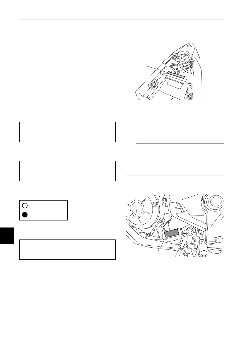
Consumer information
10-1
10
EAU26357
Identification numbers
Record the vehicle identification num-
ber, engine serial number, model label
information, and the key identification
number in the spaces provided below.
These identification numbers are need-
ed when registering the vehicle with
the authorities in your area and when
ordering spare parts from a Yamaha
dealer.
VEHICLE IDENTIFICATION NUMBER:
ENGINE SERIAL NUMBER:
MODEL LABEL INFORMATION:
KEY IDENTIFICATION NUMBER:
EAU62971
Vehicle identification number
The vehicle identification number is
stamped into the frame under the pas-
senger seat. (See page 4-18.)
TIP
The vehicle identification number is
used to identify your vehicle and may
be used to register it with the licensing
authority in your area.
EAU26442
Engine serial number
The engine serial number is stamped
into the crankcase.
1. Vehicle identification number
1. Engine serial number
1
1
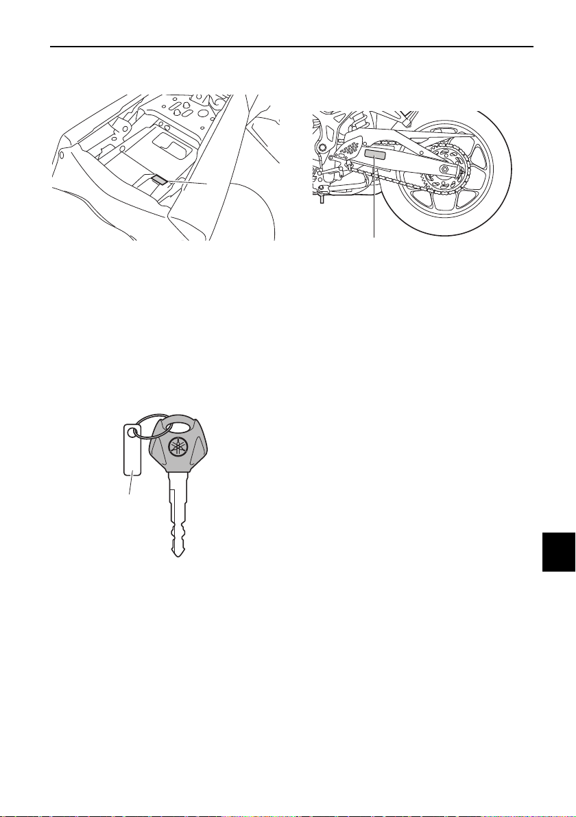
Consumer information
10-2
10
EAU26521
Model label
The model label is affixed to the frame
under the passenger seat. (See page
4-18.) Record the information on this
label in the space provided. This infor-
mation will be needed when ordering
spare parts from a Yamaha dealer.
EAU26382
Key identification number
The key identification number is
stamped into the key tag. Record this
number in the space provided and use
it for reference when ordering a new
key.
EAU48271
Vehicle Emission Control Informa-
tion label
The Vehicle Emission Control Informa-
tion label is affixed at the location in the
illustration. This label shows specifica-
tions related to exhaust emissions as
required by federal law, state law and
Environment Canada.
1. Model label
1. Key identification number
1
1
1. Vehicle Emission Control Information label
1

Consumer information
10-3
10
EAU90250
Vehicle data recording
This model’s ECU stores certain vehi-
cle data to assist in the diagnosis of
malfunctions and for research, statisti-
cal analysis and development purpos-
es.
Although the sensors and recorded
data will vary by model, the main data
points are:
z Vehicle status and engine perfor-
mance data
z Fuel-injection and emission-relat-
ed data
z With the consent of the vehicle
owner
z Where obligated by law
z For use by Yamaha in litigation
z When the data is not related to an
individual vehicle nor owner
This data will be uploaded only when a
special Yamaha diagnostic tool is at-
tached to the vehicle, such as when
maintenance checks or service proce-
dures are performed.
Vehicle data uploaded will be handled
appropriately according to the follow-
ing Privacy Policy.
Privacy Policy
https://www.yamaha-motor.com/
privacy-policy
Yamaha will not disclose this data to a
third party except in the following cas-
es. In addition, Yamaha may provide
vehicle data to a contractor in order to
outsource services related to the han-
dling of vehicle data. Even in this case,
Yamaha will require the contractor to
properly handle the vehicle data we
provided and Yamaha will appropriate-
ly manage the data.

Consumer information
10-4
10
EAU26553
Reporting safety defects
If you believe that your vehicle has a defect which could cause a crash or could
cause injury or death, you should immediately inform the National Highway Traffic
Safety Administration (NHTSA) in addition to notifying Yamaha Motor Corpora-
tion, U.S.A. If NHTSA receives similar complaints, it may open an investigation,
and if it finds that a safety defect exists in a group of vehicles, it may order a recall
and remedy campaign. However, NHTSA cannot become involved in individual
problems between you, your dealer, or Yamaha Motor Corporation, U.S.A.
To contact NHTSA, you may call the Vehicle Safety Hotline toll-free at 1-888-327-
4236 (TTY: 1-800-424-9153); go to http://www.safercar.gov; or write to: Adminis-
trator, NHTSA, 1200 New Jersey Avenue, SE, West Building, Washington, DC
20590. You can also obtain other information about motor vehicle safety from
http://www.safercar.gov.
Consumer information
10-5
10
EAU26561
Motorcycle noise regulation
TAMPERING WITH NOISE CONTROL SYSTEM PROHIBITED:
Federal law prohibits the following acts or the causing thereof: (1) The removal or
rendering inoperative by any person other than for purposes of maintenance, re-
pair, or replacement of any device or element of design incorporated into any new
vehicle for the purpose of noise control prior to its sale or delivery to the ultimate
purchaser or while it is in use or (2) the use of the vehicle after such device or el-
ement of design has been removed or rendered inoperative by any person.
“AMONG THOSE ACTS PRESUMED TO CONSTITUTE TAMPERING ARE THE
ACTS LISTED BELOW”.
These acts include tampering with the following systems; i.e., modification, re-
moval, etc.
Exhaust system
•Muffler
•Exhaust pipe
• Silencer
Intake system
• Air cleaner case
• Air cleaner element
• Intake duct
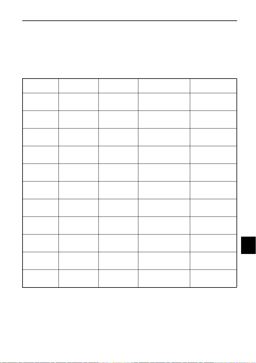
Consumer information
10-6
10
EAU69010
Maintenance record
Copies of work orders and/or receipts for parts purchased and installed on your
motorcycle will be required to document that maintenance has been completed
in accordance with the emissions warranty. The chart below is printed only as a
reminder that maintenance work is required. It is not acceptable proof of mainte-
nance work.
Maintenance
interval
Date of
service
Mileage
Servicing dealer
name and address
Remarks
600 mi
(1000 km) or
1 month
4000 mi
(6000 km) or
6 months
7000 mi
(11000 km) or
12 months
10000 mi
(16000 km) or
18 months
13000 mi
(21000 km) or
24 months
16000 mi
(26000 km) or
30 months
19000 mi
(31000 km) or
36 months
22000 mi
(36000 km) or
42 months
25000 mi
(41000 km) or
48 months
28000 mi
(46000 km) or
54 months
31000 mi
(51000 km) or
60 months

Consumer information
10-7
10
EAU63495
YAMAHA MOTOR CORPORATION, U.S.A. 2020 AND LATER
MODEL STREET & DUAL-PURPOSE MOTORCYCLE LIMITED
WARRANTY
Yamaha Motor Corporation, U.S.A. hereby warrants that each new Yamaha motorcycle purchased from an authorized Yamaha
motorcycle dealer in the continental United States will be free from defects in material and workmanship for the period of time
stated herein, subject to certain stated limitations.
THE PERIOD OF WARRANTY for Yamaha motorcycles originally equipped with headlight, stoplight, and turn signals shall be one
(1) year from the date of purchase, with no mileage limitation, except for the battery, which is warranted for thirty (30) days from
the date of purchase.
DURING THE PERIOD OF WARRANTY any authorized Yamaha motorcycle dealer will, free of charge, repair or replace, at
Yamaha’s option, any part adjudged defective by Yamaha due to faulty workmanship or material from the factory. Parts used in
warranty repairs will be warranted for the balance of the product’s warranty period. All parts replaced under warranty become the
property of Yamaha Motor Corporation, U.S.A.
GENERAL EXCLUSIONS from this warranty shall include any failures caused by:
a. Competition or racing use.
b. Installation of parts or accessories that are not qualitatively equivalent to genuine Yamaha parts.
c. Abnormal strain, neglect, or abuse.
d. Lack of proper maintenance and off-season storage as described in the Owner’s Manual.
e. Accident or collision damage.
f. Modification to original parts.
g. Damage due to improper transportation
SPECIFIC EXCLUSIONS from this warranty shall include parts replaced due to normal wear or routine maintenance.
THE CUSTOMER’S RESPONSIBILITY under this warranty shall be to:
1. Operate and maintain the motorcycle as specified in the appropriate Owner’s Manual, and
2. Give notice to an authorized Yamaha motorcycle dealer of any and all apparent defects within ten (10) days after discovery,
and make the machine available at that time for inspection and repairs at such dealer’s place of business.
WARRANTY TRANSFER: To transfer the warranty from the original purchaser to any subsequent purchaser, it is imperative that
the machine be inspected and registered for warranty by an authorized Yamaha motorcycle dealer. In order for this warranty to
remain in effect, this inspection and registration must take place within ten (10) days after transfer. A reasonable dealer-imposed
fee may be charged for the inspection.
EMISSIONS CONTROL SYSTEM WARRANTY
Yamaha Motor Corporation, U.S.A. also warrants to the ultimate purchaser and each subsequent purchaser of each Yamaha
motorcycle covered by this warranty that the vehicle is designed, built, and equipped so as to conform at the time of sale with all
U.S. emissions standards applicable at the time of manufacture and that it is free from defects in materials and workmanship
which would cause it not to meet these standards within the periods listed immediately below. Failures other than those resulting
from defects in material or workmanship which arise solely as a result of owner abuse and/or lack of proper maintenance are not
covered by this warranty.
ENGINE DISPLACEMENT PERIOD
50cc to 169cc 12,000 km (7,465 miles) or five years, whichever occurs first
Under 50cc 6,000 km (3,750 miles) or five years, whichever occurs first
170cc to 279cc 18,000 km (11,185 miles) or five years, whichever occurs first
280cc or over 30,000 km (18,641 miles) or five years, whichever occurs first
YAMAHA MOTOR CORPORATION, U.S.A. MAKES NO OTHER WARRANTY OF ANY KIND, EXPRESSED OR IMPLIED. ALL
IMPLIED WARRANTIES OF MERCHANTABILITY AND FITNESS FOR A PARTICULAR PURPOSE WHICH EXCEED THE
OBLIGATIONS AND TIME LIMITS STATED IN THIS WARRANTY ARE HEREBY DISCLAIMED BY YAMAHA MOTOR
CORPORATION, U.S.A. AND EXCLUDED FROM THIS WARRANTY.
SOME STATES DO NOT ALLOW LIMITATIONS ON HOW LONG AN IMPLIED WARRANTY LASTS, SO THE ABOVE
LIMITATIONS MAY NOT APPLY TO YOU. ALSO EXCLUDED FROM THIS WARRANTY ARE ANY INCIDENTAL OR
CONSEQUENTIAL DAMAGES INCLUDING LOSS OF USE. SOME STATES DO NOT ALLOW THE EXCLUSION OR
LIMITATION OF INCIDENTAL OR CONSEQUENTIAL DAMAGES, SO THE ABOVE EXCLUSION MAY NOT APPLY TO YOU.
THIS WARRANTY GIVES YOU SPECIFIC LEGAL RIGHTS, AND YOU MAY ALSO HAVE OTHER RIGHTS WHICH VARY
FROM STATE TO STATE.
YAMAHA MOTOR CORPORATION, U.S.A.
Post Office Box 6555
Cypress, California 90630
1-800-962-7926

Consumer information
10-8
10
WARRANTY QUESTIONS AND ANSWERS
Q. What costs are my responsibility during the warranty period?
A. The customer’s responsibility includes all costs of normal maintenance services, non-warranty repairs, accident and collision
damages, and oil, oil filters, air filters, spark plugs, and brake shoes.
Q. What are some examples of “abnormal” strain, neglect, or abuse?
A. These terms are general and overlap each other in areas. Specific examples include: Running the machine out of oil,
sustained high rpm, full-throttle, operating the machine with a broken or damaged part which causes another part to fail,
damage or failure due to improper or careless transportation and/or tie-down. If you have any specific questions on operation
or maintenance, please contact your dealer for advice.
Q. Does the warranty cover incidental costs such as towing or transportation due to a failure?
A. No. The warranty is limited to repair of the machine itself.
Q. May I perform any or all of the recommended maintenance shown in the Owner’s Manual instead of having the dealer do
them?
A. Yes, if you are a qualified mechanic and follow the procedures specified in the Owner’s and Service Manual. We do
recommend, however, that items requiring special tools or equipment be done by a Yamaha motorcycle dealer.
Q. Will the warranty be void or cancelled if I do not operate or maintain my new motorcycle exactly as specified in the Owner’s
Manual?
A. No. The warranty on a new motorcycle cannot be “voided” or “cancelled.” However, if a particular failure is caused by
operation or maintenance other than as described in the Owner’s Manual, that failure may not be covered under
warranty.
Q. What responsibility does my dealer have under this warranty?
A. Each Yamaha motorcycle dealer is expected to:
1. Completely set up every new machine before sale.
2. Explain the operation, maintenance, and warranty requirements to your satisfaction at the time of sale, and upon your
request at any later date.
3. Each Yamaha motorcycle dealer is held responsible for his setup, service and warranty repair work.
Q. Is the warranty transferable to second owners?
A. Yes. The remainder of the existing warranty can be transferred upon request. The unit has to be inspected and re-registered
by an authorized Yamaha motorcycle dealer for the policy to remain effective.
CUSTOMER SERVICE
If your machine requires warranty service, you must take it to any authorized Yamaha motorcycle dealer within the continental
United States. Be sure to bring your warranty registration card or other valid proof of the original date of purchase. If a question or
problem arises regarding the warranty, first contact the owner of the dealership. Since all warranty matters are handled at the
dealer level, this person is in the best position to help you. IF you are still not satisfied and require additional assistance, please
write to:
YAMAHA MOTOR CORPORATION, U.S.A.
CUSTOMER RELATIONS DEPARTMENT
P.O. Box 6555
Cypress, California 90630
When contacting Yamaha Motor Corporation, U.S.A., don’t forget to include any important information such as names, addresses,
model, VIN (vehicle identification number), dates, and receipts.
CHANGE OF ADDRESS
The federal government requires each manufacturer of a motor vehicle to maintain a complete, up-to-date list of all first
purchasers against the possibility of a safety-related defect and recall. This list is compiled from the purchase registrations sent to
Yamaha Motor Corporation, U.S.A. by the selling dealer at the time of your purchase.
If you should move after you have purchased your new motorcycle, please advise us of your new address by sending a postcard
listing your motorcycle model name, VIN number, dealer number (or dealer’s name) as it is shown on your warranty card, your
name and new mailing address. Mail to:
YAMAHA MOTOR CORPORATION, U.S.A.
1270 Chastain Road
Kennesaw, GA 30144
Attention: Warranty Department
This will ensure that Yamaha Motor Corporation, U.S.A. has an up-to-date registration record in accordance with federal law.

Consumer information
10-9
10
EAU63503
YAMAHA EXTENDED SERVICE (Y.E.S.)
Keep your Yamaha protected even after your limited warranty expires with genuine Yamaha
Extended Service (Y.E.S.).
This excellent Y.E.S. plan coverage is only available to Yamaha owners like you, and only while
your Yamaha is still within the Yamaha Limited Warranty period. So visit your authorized Yamaha
dealer to get all the facts. They can show you how easy it is to protect your investment with
Yamaha Extended Service.
• Y.E.S. is designed and administered by Yamaha Motor Corporation to provide maximum owner
satisfaction. It provides uninterrupted factory-backed coverage for extra peace of mind.
• Y.E.S. is flexible. You choose the plan that’s right for you: 12 months, 24 months, 36 months or,
on certain models, even 48 months beyond your warranty period.
• Y.E.S. is designed and administered by the same Yamaha people who handle your warranty –
and it shows in the comprehensive coverage benefits. There are no mileage limitations.
Coverage isn’t limited to “moving parts” or the “drivetrain” like many other plans. And Y.E.S.
covers manufacturing defects just like the warranty. See the sample contract at your Yamaha
dealer to see how comforting uninterrupted factory-backed protection can be.
• You don’t have to pay anything for covered repairs. There’s no deductible to pay, and repairs
aren’t “pro-rated.” You don’t have any “out-of-pocket” expenses for covered repairs.
• In addition, Travel and Recreation Interruption Protection (TRIP) is included at no extra cost.
TRIP gives you up to $250 reimbursement per occurrence for any reasonable expenses you
incur because your Yamaha needs covered service: replacement vehicle rental, emergency
towing, phone calls, even food and lodging when you are away from home. This superb
coverage goes into effect when you purchase Y.E.S., so it applies to any warranty repairs as
well as covered repairs during your entire Y.E.S. plan period.
• Y.E.S. coverage is honored at any authorized Yamaha dealer nationwide.
• Y.E.S. coverage is transferable to a new owner if you sell or trade-in. That can make your
Yamaha much more valuable!
Consumer information
10-10
10
We urge you to act now. You’ll get the excellent benefits of TRIP coverage right away, and you’ll
rest easy knowing you’ll have strong factory-backed protection even after your Yamaha Limited
Warranty expires.
A special note:
If visiting your dealer isn’t convenient, contact Yamaha with your VIN number and we’ll be happy
to help you get the Y.E.S. coverage you need.
Yamaha Service Marketing
P.O. Box 6555
Cypress, CA 90630
1-(866)-YES-EXTD (1-866-937-3983)
YAMAHA EXTENDED SERVICE

11-1
11
Index
A
ABS.......................................................4-14
ABS warning light ...................................4-3
Air filter element and check hose,
replacing and cleaning .......................7-13
B
Battery ..................................................7-29
Brake and clutch levers,
checking and lubricating ....................7-26
Brake and shift pedals,
checking and lubricating ....................7-26
Brake fluid, changing ............................7-22
Brake fluid level, checking ....................7-21
Brake lever............................................4-13
Brake lever free play, checking.............7-19
Brake light switches..............................7-20
Brake pedal...........................................4-13
C
Cables, checking and lubricating .........7-25
Canister...................................................7-8
Care ........................................................8-1
Catalytic converter................................4-17
Clock.......................................................4-5
Clutch lever...........................................4-12
Clutch lever free play, adjusting ...........7-18
Coolant .................................................7-12
Coolant temperature meter ....................4-5
D
Data recording, vehicle .........................10-3
Dimmer switch......................................4-10
Display units, switching ..........................4-4
Drive chain, cleaning and lubricating....7-24
Drive chain slack...................................7-23
E
Engine break-in.......................................6-1
Engine oil and oil filter cartridge .............7-8
Engine overheating ...............................7-37
Engine serial number ............................10-1
Engine trouble warning light ...................4-3
F
Front and rear brake pads, checking....7-20
Front fork, checking..............................7-28
Fuel .......................................................4-15
Fuel meter...............................................4-4
Fuel tank cap ........................................4-15
Fuel tank overflow hose ........................4-17
Fuses, replacing....................................7-31
H
Handlebar switches ..............................4-10
Hazard switch .......................................4-11
Helmet holders ..................................... 4-19
High beam indicator light ....................... 4-2
Horn switch .......................................... 4-11
I
Identification numbers.......................... 10-1
Ignition circuit cut-off system............... 4-23
Indicator lights and warning lights ......... 4-2
K
Key identification number .................... 10-2
L
Labels, location ...................................... 1-1
License plate light bulb, replacing........ 7-33
Luggage strap holders ......................... 4-22
M
Main switch/steering lock....................... 4-1
Maintenance and lubrication, periodic... 7-4
Maintenance,
emission control system ...................... 7-3
Maintenance record ............................. 10-6
Matte color, caution ............................... 8-1
Model label........................................... 10-2
Multi-function display............................. 4-6
Multi-function meter unit ........................ 4-4
N
Neutral indicator light ............................. 4-2
Noise regulation ................................... 10-5
O
Oil pressure warning light....................... 4-2
P
Parking ................................................... 6-5
Part locations ......................................... 3-1
Pass switch .......................................... 4-10
S
Safety defects, reporting...................... 10-4
Safety information .................................. 2-1
Seats .................................................... 4-18
Self-diagnosis device ............................. 4-9
Shift indicator light ................................. 4-3
Shift indicator light control mode ........... 4-8
Shifting ................................................... 6-3
Shift pedal ............................................ 4-12
Shock absorber assembly, adjusting ... 4-21
Sidestand ............................................. 4-22
Sidestand, checking and lubricating.... 7-27
Spark plugs, checking............................ 7-7
Specifications......................................... 9-1
Speedometer.......................................... 4-4
Start/Engine stop switch ...................... 4-11
Starting the engine ................................. 6-2
Steering, checking................................ 7-28

Index
11-2
11
Storage................................................... 8-4
Storage compartment .......................... 4-20
Supporting the motorcycle................... 7-34
Swingarm pivots, lubricating................ 7-27
T
Tachometer ............................................ 4-4
Throttle grip and cable,
checking and lubricating.................... 7-25
Throttle grip free play, checking........... 7-15
Tires...................................................... 7-16
Tool kit.................................................... 7-2
Transmission gear display...................... 4-5
Troubleshooting ................................... 7-35
Troubleshooting chart .......................... 7-36
Turn signal indicator lights ..................... 4-2
Turn signal switch ................................ 4-11
V
Valve clearance .................................... 7-15
Vehicle Emission Control Information
label ................................................... 10-2
Vehicle identification number............... 10-1
Vehicle lights ........................................ 7-33
W
Warranty, extended.............................. 10-9
Warranty, limited .................................. 10-7
Wheel bearings, checking.................... 7-29
Wheels.................................................. 7-18
Y
Yamalube ............................................. 7-11


EAU66301
For your best ownership experience, think Genuine Yamaha!
Genuine Yamaha Parts – Genuine Yamaha replacement parts are the exact
same parts as the ones originally equipped on your vehicle, providing you
with the performance and durability you have come to expect. Why settle for
aftermarket parts that may not provide full confidence and satisfaction?
Genuine Yamaha Accessories – Yamaha only offers accessories that meet
our high standards for quality and performance. Buy with confidence,
knowing your Genuine Yamaha Accessories will fit right and perform right –
right out of the box.
Yamalube – Take care of your Yamaha with legendary Yamalube oils,
lubricants, and care products. They’re formulated and approved by the
toughest judges we know: the Yamaha engineering teams that know your
Yamaha from the inside out.
Genuine Yamaha Service Manuals – Get the same factory manual for your
vehicle that the technicians at your authorized Yamaha dealer use. Service
manuals are available through your Yamaha dealer or you can order them
directly through yamahapubs.com (for US consumers only).
Genuine Yamaha products are available only from your Yamaha dealer.
Find out more at:
For US consumers, please visit yamaha-motor.com
For Canadian consumers, please visit yamaha-motor.ca

PRINTED IN INDONESIA
2021.10
