Owner's Manual _'_ dr
CRAFTSMAN°
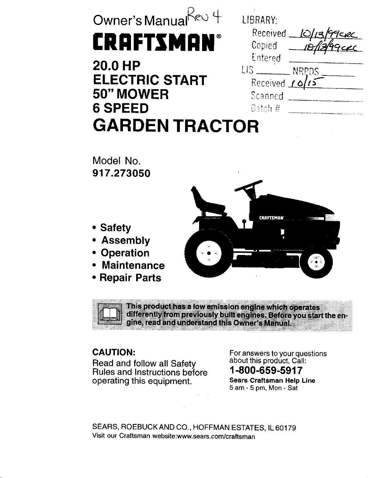
20.0 HP
ELECTRIC START
50" MOWER
6 SPEED
LIBRARY;
Receivedcopied
Entered
LiSRcceived (NR!_9_Sf --
Scan,_cd
GARDEN TRACTOR
Model No
917.273050
• Safety
• Assembly
• Operation
• Maintenance
• Repair Parts
CAUTION:
Read and follow all Safety
Rules and Instructions before
operating this equipment.
For answers to your questions
about this product, Call:
1-800-659-5917
Sears Craftsman Help Une
5 am- 5 pm, Mon- Sat
SEARS, ROEBUCK AND CO., HOFFMAN ESTATES, IL 60179
Visit our Craftsman website:www.sears.com/craftsman

Warranty ...............................................2
Safety Rules ................................. ......... 2
Product Specifications .......................... 5
Assembly ............................................... 8
Operation ............................................ 12
Maintenance Schedule ...................... 18
Maintenance ....................................... 18
Service and Adjustments .................... 22
Storage ............................................... 29
Troubleshooting ................................. 30
Repair Parts ........................................ 34
Parts Ordering ..................... Back Cover
LIMITED TWO YEAR WARRANTY ON CRAFTSMAN RIDING EQUIPMENT
For two (2) years from the date of purchase, if this Craftsman Riding Equipment is
maintained, lubricated and tuned up according to the instructions in the owner's
manual, Sears will repair or replace, free of charge, any parts found to be defective in
material or workmanship.
This Warranty does not cover:
• Expendable items which become worn during normal use, such as blades, spark
plugs, air cleaners, belts, etc.
• Tire replacement or repair caused by punctures from outside objects, such as nails,
thorns, stumps, or glass.
• Repairs necessary because of operator abuse, negligence, improper storage or
accident or the failure to maintain the equipment according to the instructions
contained in the owner's manual.
• Riding equipment used for commercial or rental purposes.
LIMITED 90 DAY WARRANTY ON BAI-IERY
For ninety (90) days from date of purchase, if any battery included with this riding
equipment proves defective in material or workmanship and our testing determines the
battery wil! not hold a charge, Sears will replace the battery at no charge. In-home
warranty service on your Craftsman riding equipment is available at no charge for 30
days from the date of purchase. Please contact your nearest service center. After 30
days from the date of purchase, warranty service is available by taking your Craftsman
riding equipment to your nearest Sears Service Center. (In-home warranty service will
still be available after 30 days from the date of purchase but a standard trip charge will
apply). This warranty applies only while this product is in the United States. This
Warranty gives you specific legal rights, and you may also have other rights which may
vary from state to state.
Sears, Roebuck and Co., D/817 WA, Hoffman Estates, IL 60179
IMPORTANT: This cutting machine is
capable of amputating hands and feet
and throwing objects. Failure to observe
the following safety instructions could
result in serious injury or death.
GENERAL OPERATION
• Read, understand, and follow all
instructions in the manual and on the
machine before starting.
• Only allow responsible adults, who are
familiar with the instructions, to
operate the machine.
• Clear the area of objects such as
rocks, toys, wire, etc., which could be
picked up and thrown by the blade.
2
• Be sure the area is clear of other
people before mowing. Stop machine
if anyone enters the area.
• Never carry passengers.
• Do not mow in reverse unless abso-
lutely necessary. Always look down
and behind before and while backing.
• Be aware of the mower discharge
direction and do not point it at anyone.
Do not operate the mower without
either the entire grass catcher or the
guard in place.
Slow down before turning.
• Never leave a running machine
unattended. Always turn off blades, set
parking brake, stop engine, and
remove keys before dismounting.
• Turn off blades when not mowing.
• Stop engine before removing grass
catcher or unclogging chute.
• Mow only in daylight or good artificial
light.
• Do not operate the machine while
under the influence of alcohol or
drugs.
• Watch for traffic when operating near
or crossing ro_idways.
• Use extra care when loading or
unloading the machine into a trailer or
truck.
• Data indicates that operators, age 60
years and above, are involved in a
large percentage of riding mower-
related injuries. These operators
should evaluate their ability to operate
the riding mower safely enough to
protect themselves and others from
serious injury.
SLOPE OPERATION
Slopes are a major factor related to loss-
of-control and tipover accidents, which
can result in severe injury or death. All
slopes require extra caution. If you
cannot back up the slope or if you feel
uneasy on it, do not mow it.
DO:
• Mow up and down slopes, not across.
• Remove obstacles such as rocks, tree
limbs, etc.
• Watch for holes, ruts, or bumps.
Uneven terrain could overturn the
machine. Tall grass can hide ob-
stacles.
• Use slow speed. Choose a low gear
so that you will not have to stop or shift
while on the slope.
• Follow the manufacturer's recommen-
dations for wheel weights or counter-
weights to improve stability.
• Use extra care with grass catchers or
other attachments. These can change
the stability of the machine.
• Keep all movement on the slopes slow
and gradual. Do not make sudden
changes in speed or direction.
• Avoid starting or stopping on a slope. If
tires lose traction, disengage the
blades and proceed slowly straight
down the slope.
DO NOT:
• Do notturn on slopes unless neces-
sary, and then, turn slowly and
gradually downhill, if possible.
• Do not mow near drop-offs, ditches, or
embankments. The mower could
suddenly turn over if a wheel is over
the edge of a cliff or ditch, or if an edge
caves in.
• Do not mow on wet grass. Reduced
traction could cause sliding.
• Do nottry to stabilize the machine by
putting your foot on the ground.
• Do not use grass catcher on steep
slopes.
CHILDREN
Tragic accidents can occur if the operator
is not alert to the presence of children.
Children are often attracted to the
machine and the mowing activity. Never
assume that children will remain where
you last saw them.
• Keep children out of the mowing area
and under the watchful care of another
responsible adult.
• Be alert and turn machine off if
children enter the area.
• Before and when backing, look behind
and down for small children.
• Never carry children. They may fall off
and be seriously injured or interfere
with safe machine operation.
• Never allow children to operate the
machine.
• Use extra care when approaching
blind corners, shrubs, trees, or other
objects that may obscure vision.
SERVICE
• Use extra care in handling gasoline
and other fuels. They are flammable
and vapors are explosive.
Use only an approved container.
Never remove gas cap or add fuel
with the engine running. Allow
engine to cool before refueling. Do
not smoke.
Never refuel the machine indoors.
Never store the machine or fuel
container inside where there is an
open flame, such as a water heater.
3
• Never run a machine inside a closed
area.
• Keep nuts and bolts, especially blade
attachment bolts, tight and keep
equipment in good condition.
• Never tamper with safety devices.
Check their proper operation regularly.
• Keep machine free of grass, leaves, or
other debris build-up. Clean oil or fuel
spillage. Allow machine to cool before
storing.
Stop and inspect the equipment if you
strike an object. Repair, if necessary,
before restarting.
Never make adjustments or repairs
with the engine running.
Grass catcher components are subject
to wear, damage, and deterioration,
which could expose moving parts or
allow objects to be thrown. Frequently
check components and replace with
manufacturer's recommended parts,
when necessary.
• Mower blades are sharp and can cut.
Wrap the blade(s) or wear gloves, and
use extra caution when servicing
them.
• Check brake operation frequently.
Adjust and service as required.
• Be sure the area is clear of other
people before mowing. Stop machine
if anyone enters the area.
• Never carry passengers.
• Do not mow in reverse unless abso-
lutely necessary. Always look down
and behind before and while backing.
• Never carry children. They may fall off
and be seriously injured or interfere
with safe machine operation.
• Keep children out of the mowing area
and under the watchful care of another
responsible adult.
• Be alert and turn machine off if
children enter the area.
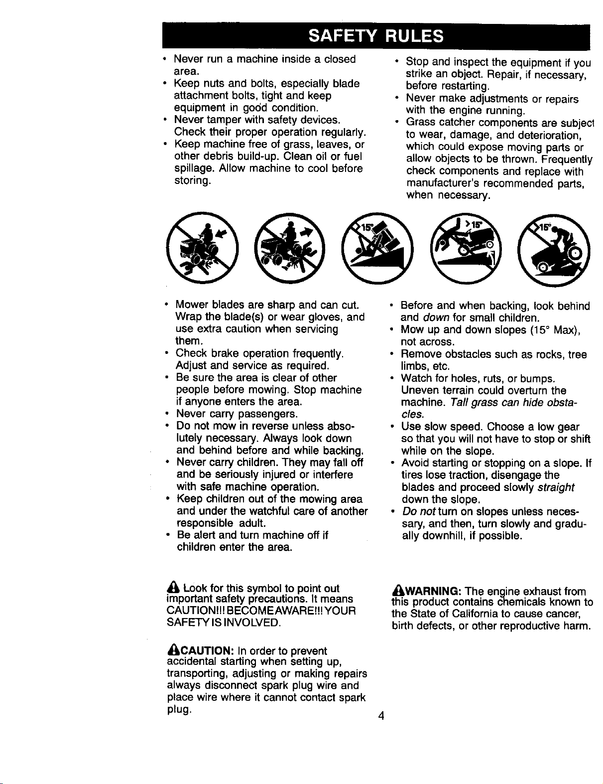
Before and when backing, look behind
and down for small children.
Mow up and down slopes (15 ° Max),
not across.
Remove obstacles such as rocks, tree
limbs, etc.
Watch for holes, ruts, or bumps.
Uneven terrain could overturn the
machine. Tall grass can hide obsta-
cles.
Use slow speed. Choose a low gear
so that you will not have to stop or shift
while on the slope.
Avoid starting or stopping on a slope. If
tires lose traction, disengage the
blades and proceed slowly straight
down the slope.
Do not turn on slopes unless neces-
sary, and then, turn slowly and gradu-
ally downhill, if possible.
Look for this symbol to point out
important safety precautions. It means
CAUTION!!! BECOMEAWARE!!! YOUR
SAFETY IS INVOLVED.
_CAUTION: In order to prevent
accidental starting when setting up,
transporting, adjusting or making repairs
always disconnect spark plug wire and
place wire where it cannot contact spark
plug.
• LWARNING: The engine exhaust from
this product contains chemicals known to
the State of California to cause cancer,
birth defects, or other reproductive harm.
4
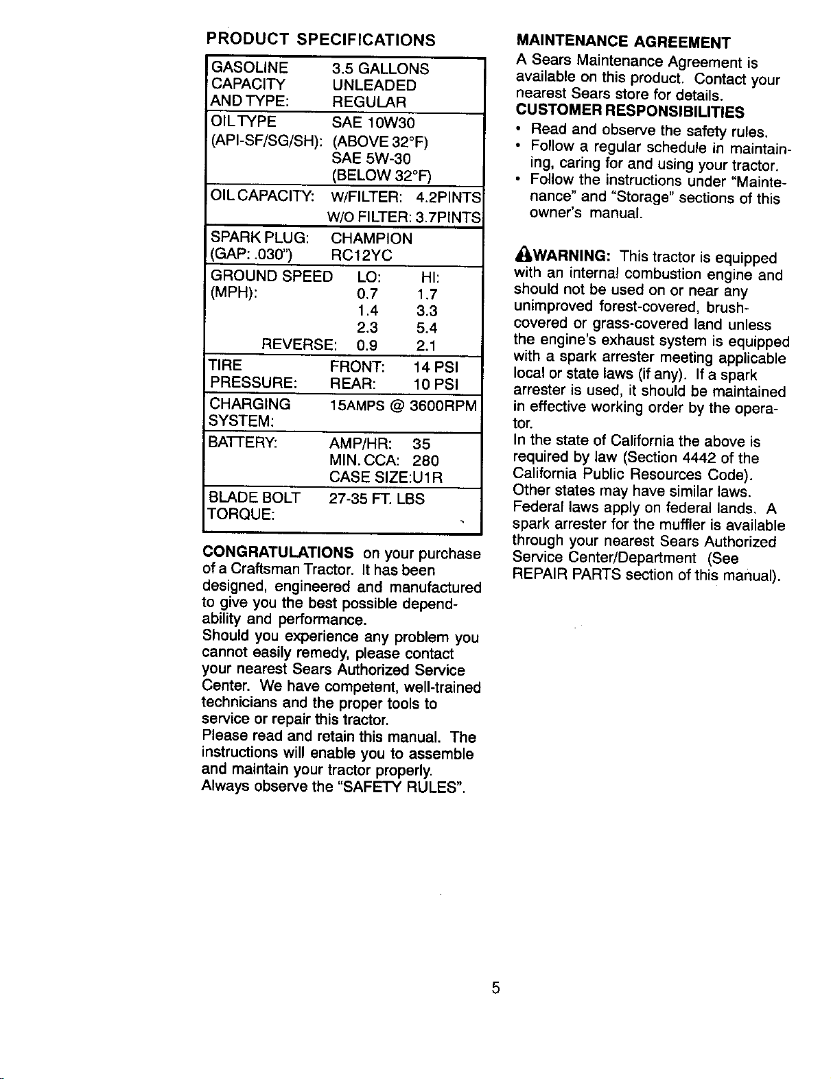
PRODUCT SPECIFICATIONS
GASOLINE 3.5 GALLONS
CAPACITY UNLEADED
AND TYPE: REGULAR
)ILTYPE SAE 10W30
&PI-SF/SG/SH): (ABOVE 32°F)
SAE 5W-30
(BELOW 32°F)
)ILCAPACITY: W/FILTER: 4.2PINTS
W/O FILTER: 3.7PINTS
_PARK PLUG: CHAMPION
GAP: .030") RC12YC
GROUND SPEED LO: HI:
MPH): 0.7 1.7
1.4 3.3
2.3 5.4
REVERSE: 0.9 2.1
TIRE FRONT: 14 PSI
PRESSURE: REAR: 10 PSI
CHARGING 15AMPS @ 3600RPM
SY ST EM:
3AI-I-E RY: AMP/HR: 35
MIN. CCA: 280
CASE SIZE:U 1R
3LADE BOLT 27-35 FT. LBS
TORQUE:
CONGRATULATIONS on your purchase
of a Craftsman Tractor. It has been
designed, engineered and manufactured
to give you the best possible depend-
ability and performance.
Should you experience any problem you
cannot easily remedy, please contact
your nearest Sears Authorized Service
Center. We have competent, well-trained
technicians and the proper tools to
service or repair this tractor.
Please read and retain this manual. The
instructions will enable you to assemble
and maintain your tractor properly.
Always observe the "SAFETY RULES".
MAINTENANCE AGREEMENT
A Sears Maintenance Agreement is
available on this product. Contact your
nearest Sears store for details.
CUSTOMER RESPONSIBILITIES
• Read and observe the safety rules.
• Follow a regular schedule in maintain-
ing, caring for and using your tractor.
• Follow the instructions under "Mainte-
nance" and "Storage" sections of this
owner's manual.
_WARNING: This tractor is equipped
with an internal combustion engine and
should not be used on or near any
unimproved forest-covered, brush-
covered or grass-covered land unless
the engine's exhaust system is equipped
with a spark arrester meeting applicable
local or state laws (if any). If a spark
arrester is used, it should be maintained
in effective working order by the opera-
tor.
In the state of California the above is
required by law (Section 4442 of the
California Public Resources Code).
Other states may have similar laws.
Federal laws apply on federal lands. A
spark arrester for the muffler is available
through your nearest Sears Authorized
Service Center/Department (See
REPAIR PARTS section of this manual).
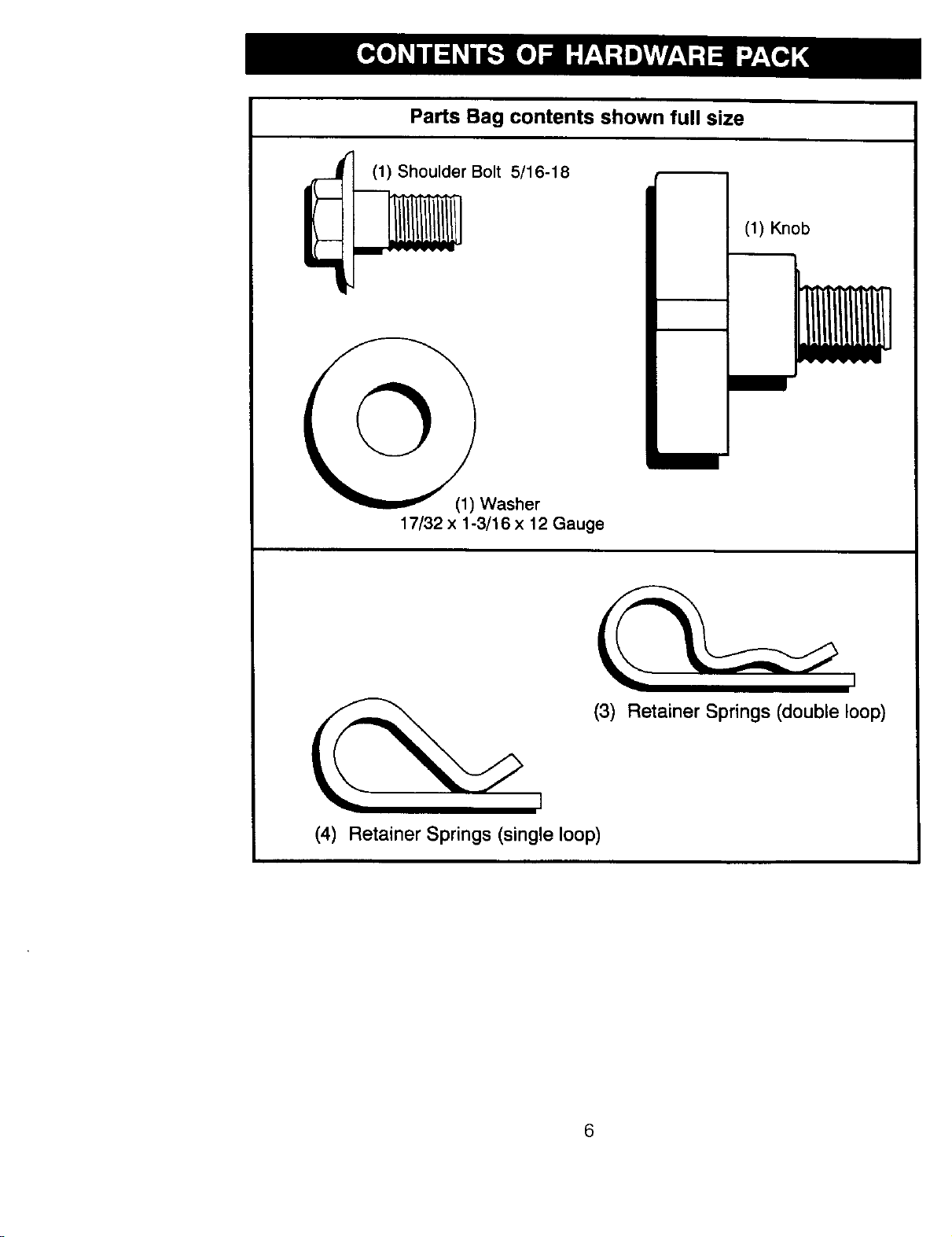
Parts Bag contents shown full size
(1) Shoulder Bolt 5/16-18
(1) Knob
17/32 x 1-3/16 x 12 Gauge
(3) Retainer Springs (double loop)
(4) Retainer Springs (single loop)
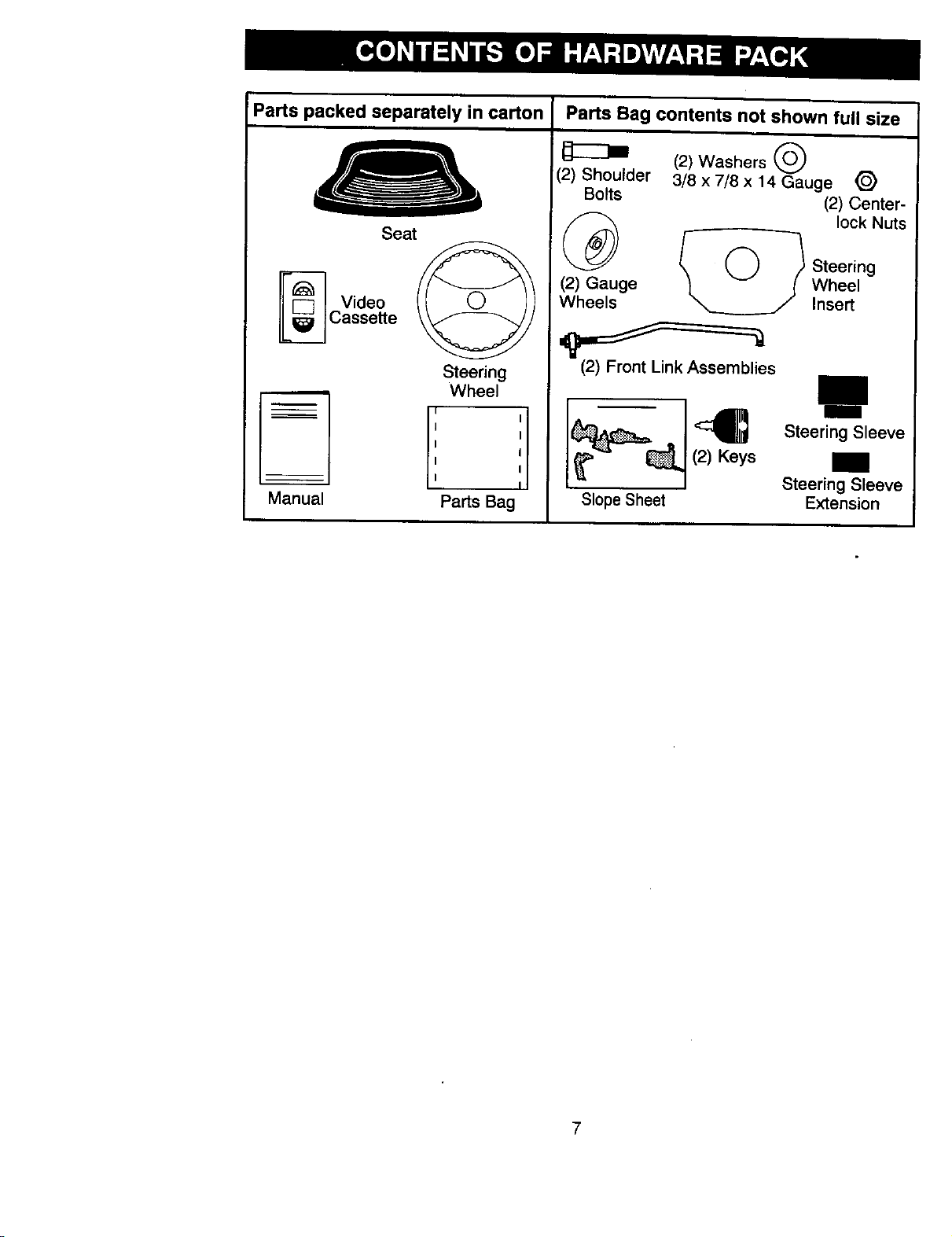
Parts packed separately in carton Parts Bag contents not shown full size
Seat
Video
Cassette
(2) Washers
(2) Shoulder 3/8 x 7/8 x 14 Gauge _)
Bolts (2) Center-
_ lock Nuts
Steering
(2) Gauge t v / Wheel
Wheels __ J Insert
Steering
Wheel
(2) Front Link Assemblies
I I
I I
I
I
I
I
I
I
Manual Parts Bag
(2) Keys
Slope Sheet
Steering Sleeve
Steering Sleeve
Extension
7
Your new tractor has been assembled at the factory with exception of those parts left
unassembled for shipping purposes. To ensure safe and proper operation of your
tractor all parts and hardware you assemble must be tightened securely. Use the
correct tools as necessary to insure proper tightness. Review the video cassette before
you begin.
TOOLS REQUIRED FOR ASSEMBLY
A socket wrench set will make assembly
easier. Standard wrench sizes you need
are listed below.
(1) 9/16"wrench (1) Pliers
(1) 1/2" wrench (1) Utility knife
(1) 3/4" socket with
drive ratchet
(1) Tire pressure gauge
When right or left hand is mentioned in
this manual, it means, from your point of
view, when you are in the operating
position (seated behind the steering
wheel).
TO REMOVE TRACTOR FROM
CARTON
UNPACK CARTON
• Remove all accessible loose parts and
parts boxes from shipping carton.
• Cut, from top to bottom, along lines on
all four corners of shipping carton, and
lay panels flat.
• Remove mower and packing materi-
als.
• Check for any additional loose parts or
boxes and remove.
_ ,..F"'_:_ Stee ring
_..-J" Wheel Insert
_- Hex Bolt
o_ Lock Washer
Steering _ Large Flat
Wheel_t(eep_i:_el
Steering _ .
Sleeve __::_'-Tabs
Extension I
Steering Shaft _ .-_\.
Steerin
Sleeve
• Snap steering wheel insert into center
of steering wheel.
• Remove protective materials from
tractor hood and grill.
IMPORTANT: Check for and remove any
staples in skid that may puncture tires
where tractor is to roll off skid.
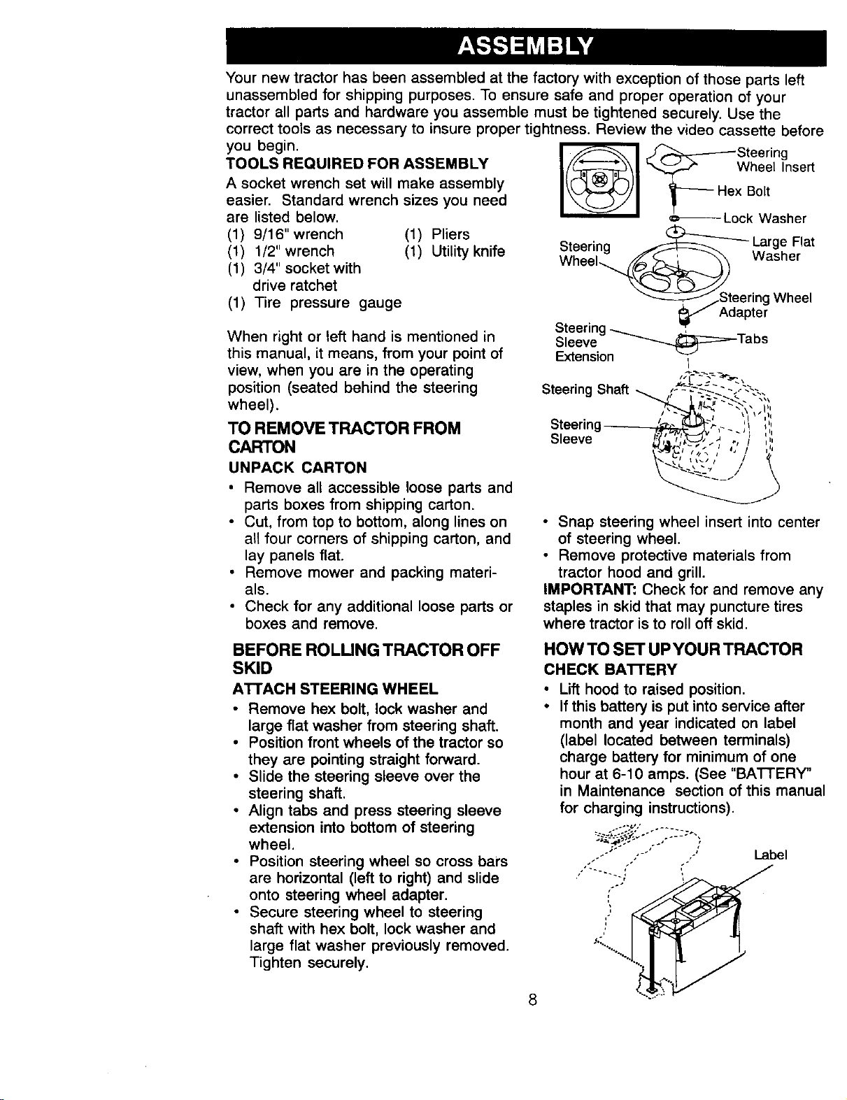
BEFORE ROLUNG TRACTOR OFF
SKID
AI'I'ACH STEERING WHEEL
• Remove hex bolt, lock washer and
large flat washer from steering shaft.
• Position front wheels of the tractor so
they are pointing straight forward.
• Slide the steering sleeve over the
steering shaft.
• Align tabs and press steering sleeve
extension into bottom of steering
wheel.
• Position steering wheel so cross bars
are horizontal (left to right) and slide
onto steering wheel adapter.
• Secure steering wheel to steering
shaft with hex bolt, lock washer and
large flat washer previously removed.
Tighten securely.
8
HOW TO SET UPYOUR TRACTOR
CHECK BA'n'ERY
Lift hood to raised position.
If this battery is put into service after
month and year indicated on label
(label located between terminals)
charge battery for minimum of one
hour at 6-10 amps. (See "BATTERY"
in Maintenance section of this manual
for charging instructions).
"" "' ' Label
'I
.<.
-..%
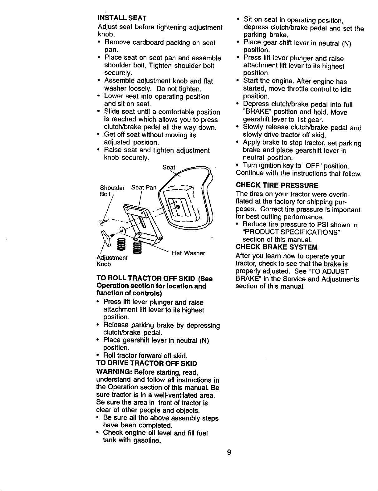
INSTALL SEAT
Adjust seat before tightening adjustment
knob.
• Remove cardboard packing on seat
pan.
• Place seat on seat pan and assemble
shoulder bolt. Tighten shoulder bolt
securely.
• Assemble adjustment knob and flat
washer loosely. Do not tighten.
• Lower seat into operating position
and sit on seat.
• Slide seat until a comfortable position
is reached which allows you to press
clutch/brake pedal all the way down.
• Get off seat without moving its
adjusted position.
• Raise seat and tighten adjustment
knob securely.
Seat
Shoulder Seat Pan
Bolt
Adjustment
Knob
Flat Washer
TO ROLLTRACTOR OFF SKID (See
Operation section for location and
function of controls)
,, Press lift lever plunger and raise
attachment lift lever to its highest
position.
• Release parking brake by depressing
clutch/brake pedal.
• Place gearshift lever in neutral (N)
position.
• Roll tractor forward off skid.
TO DRIVE TRACTOR OFF SKID
WARNING: Before starting, read,
understand and follow all instructions in
the Operation section of this manual. Be
sure tractor is in a well-ventilated area.
Be sure the area in front of tractor is
clear of other people and objects.
• Be sure all the above assembly steps
have been completed.
• Check engine oil level and fill fuel
tank with gasoline.
• Sit on seat in operating position,
depress clutch/brake pedal and set the
parking brake.
• Place gear shift lever in neutral (N)
position.
• Press lift lever plunger and raise
attachment lift lever to its highest
position.
• Start the engine. After engine has
started, move throttle control to idle
position.
• Depress clutch/brake pedal into full
"BRAKE" position and hold. Move
gearshift lever to 1st gear.
• Slowly release clutch/brake pedal and
slowly drive tractor off skid.
• Apply brake to stop tractor, set parking
brake and place gearshift lever in
neutral position.
• Turn ignition key to "OFF" position.
Continue with the instructions that follow.
CHECK TIRE PRESSURE
The tires on your tractor were overin-
flated at the factory for shipping pur-
poses. Correct tire pressure is important
for best cutting performance.
• Reduce tire pressure to PSI shown in
"PRODUCT SPECIFICATIONS"
section of this manual.
CHECK BRAKE SYSTEM
After you learn how to operate your
tractor, check to see that the brake is
properly adjusted. See "TO ADJUST
BRAKE" in the Service and Adjustments
section of this manual.
9
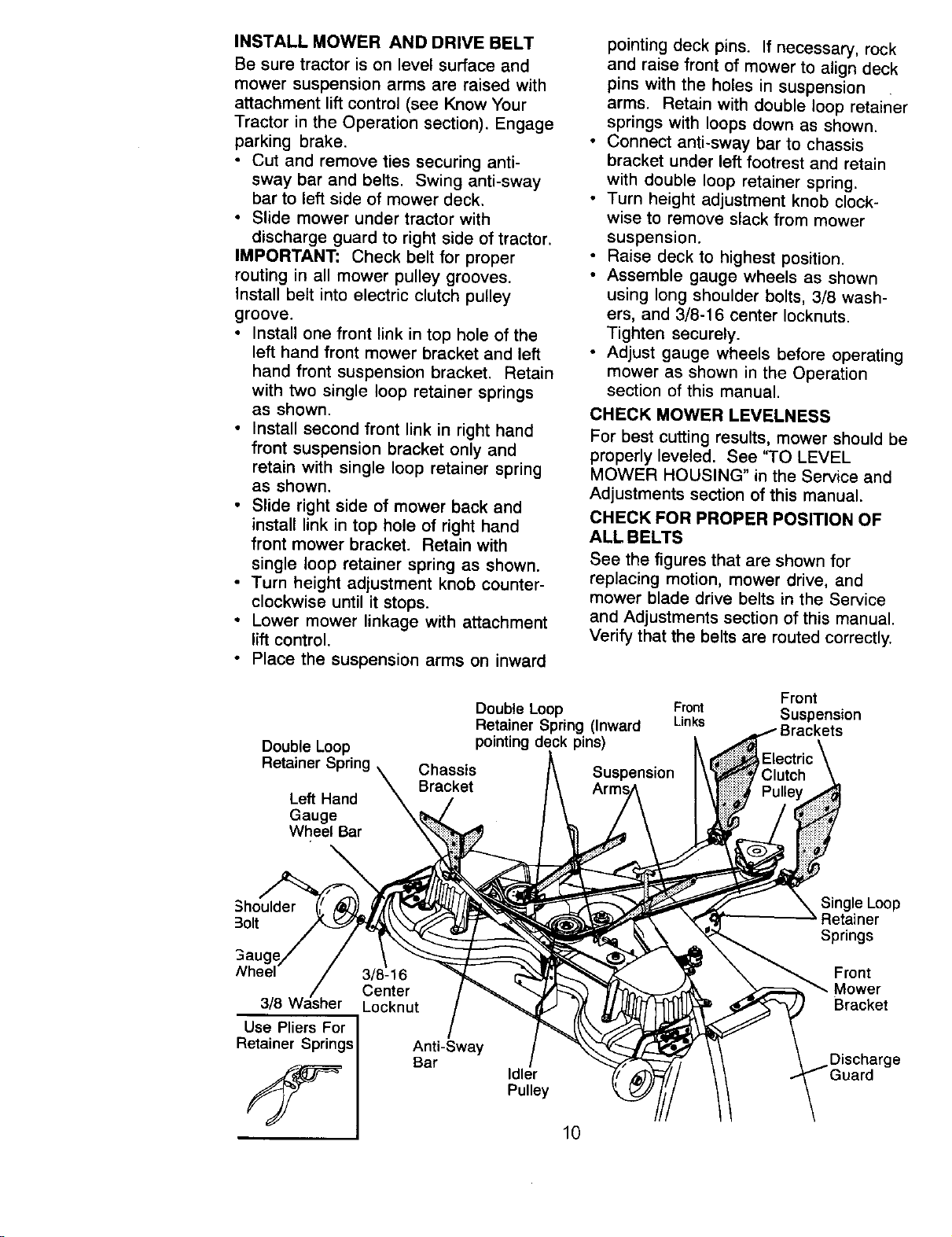
INSTALL MOWER AND DRIVE BELT
Be sure tractor is on level surface and
mower suspension arms are raised with
attachment lift control (see Know Your
Tractor in the Operation section). Engage
parking brake.
• Cut and remove ties securing anti-
sway bar and be_ts. Swing anti-sway
bar to left side of mower deck.
• Slide mower under tractor with
discharge guard to right side of tractor.
IMPORTANT: Check belt for proper
routing in all mower pulley grooves.
Install belt into electric clutch pulley
groove.
• Install one front link in top hole of the
left hand front mower bracket and left
hand front suspension bracket. Retain
with two single loop retainer springs
as shown.
• Install second front link in right hand
front suspension bracket only and
retain with single loop retainer spring
as shown.
• Slide right side of mower back and
install link in top hole of right hand
front mower bracket. Retain with
single loop retainer spring as shown.
• Turn height adjustment knob counter-
clockwise until it stops.
• Lower mower linkage with attachment
lift control.
• Place the suspension arms on inward
pointing deck pins. If necessary, rock
and raise front of mower to align deck
pins with the holes in suspension
arms. Retain with double loop retainer
springs with loops down as shown.
• Connect anti-sway bar to chassis
bracket under left footrest and retain
with double loop retainer spring.
• Turn height adjustment knob clock-
wise to remove slack from mower
suspension.
• Raise deck to highest position.
• Assemble gauge wheels as shown
using long shoulder bolts, 3/8 wash-
ers, and 3/8-1 6 center Iocknuts.
Tighten securely.
• Adjust gauge wheels before operating
mower as shown in the Operation
section of this manual.
CHECK MOWER LEVELNESS
For best cutting results, mower should be
properly leveled. See 'q-O LEVEL
MOWER PIOUSING" in the Service and
Adjustments section of this manual.
CHECK FOR PROPER POSITION OF
ALL BELTS
See the figures that are shown for
replacing motion, mower drive, and
mower blade drive belts in the Service
and Adjustments section of this manual.
Verify that the belts are routed correctly.
Double Loop
Retainer 5
Left Hand
Gauge
Wheel Bar
Double Loop
Retainer Spring (Inward
pins)
Front
Fror_ Suspension
Links
Suspension
Arm_
Shoulder
3olt
Use Pliers For
Retainer Springs
3/8-16
Center
Locknut
Anti-Sway
Bar
Idler
Pulley
Single Loop
Retainer
Springs
Front
Mower
Bracket
Discharge
10
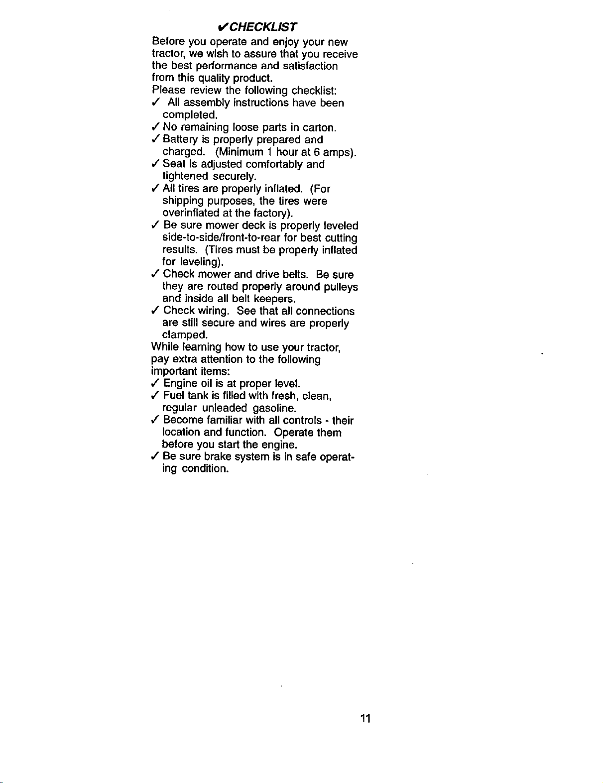
v" CHECKLIST
Before you operate and enjoy your new
tractor, we wish to assure that you receive
the best performance and satisfaction
from this quality product.
Please review the following checklist:
,/ All assembly instructions have been
completed.
/ No remaining loose parts in carton.
,/Battery is properly prepared and
charged. (Minimum 1 hour at 6 amps).
,I Seat is adjusted comfortably and
tightened securely.
,/All tires are properly inflated. (For
shipping purposes, the tires were
overinflated at the factory).
,/Be sure mower deck is properly leveled
side-to-side/front-to-rear for best cutting
results. (Tires must be properly inflated
for leveling).
•/ Check mower and drive belts. Be sure
they are routed properly around pulleys
and inside all belt keepers.
,/Check wiring. See that all connections
are still secure and wires are properly
clamped.
While learning how to use your tractor,
pay extra attention to the following
important items:
,/ Engine oil is at proper level.
,/" Fuel tank is filled with fresh, clean,
regular unleaded gasoline.
,/" Become familiar with all controls - their
location and function. Operate them
before you start the engine.
,/Be sure brake system is in safe operat-
ing condition.
11
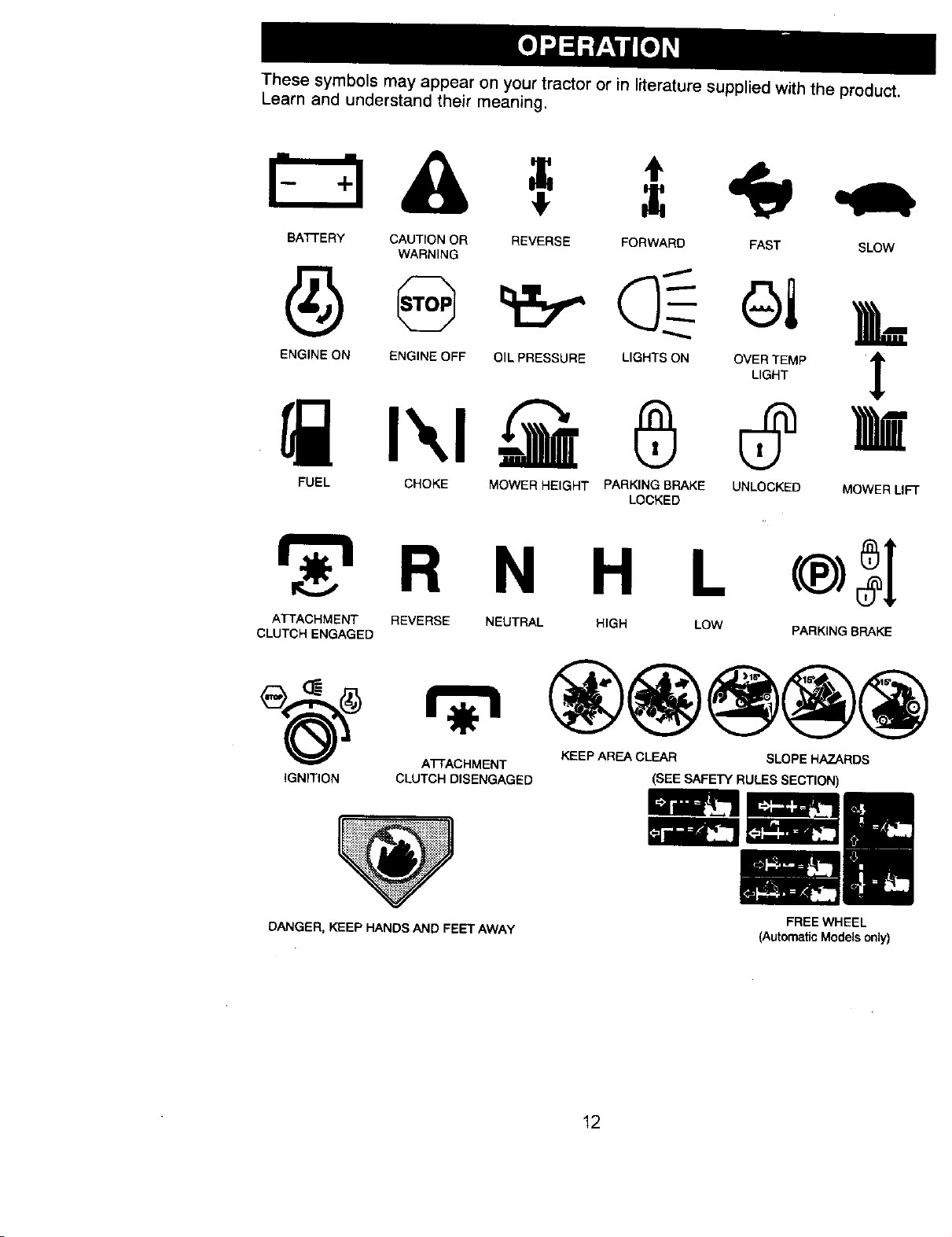
These symbols may appear on your tractor or in literature supplied with the product.
Learn and understand their meaning.
BAI-FERY CAUTION OR REVERSE FORWARD FAST SLOW
WARNING
_I_ENG'NEONI_!_IENG'NEOFFO"PRESSURE_L'G"TSON_OV_,_Mp_
FUEL CHOKE MOWER HEIGHT PARKING BRAKE UNLOCKED MOWER LIFT
LOCKED
R N H L
ATTACHMENT REVERSE NEUTRAL HIGH LOW
CLUTCH ENGAGED PARKING BRAKE
ATTACHMENT KEEP AREA CLEAR SLOPE HAZARDS
IGNITION CLUTCH DISENGAGED
i:i::iiJ::i:i_iii_....................._iii:.:.::iiiiii_iiii
(SEE SAFETY RULES SECTION)
DANGER, KEEP HANDS AND FEET AWAY
FREE WHEEL
(Automatic Models only)
12
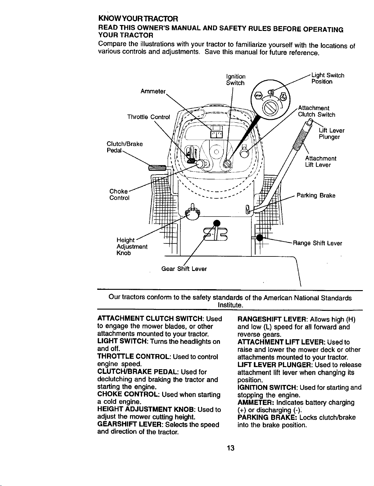
KNOW YOUR TRACTOR
READ THIS OWNER'S MANUAL AND SAFETY RULES BEFORE OPERATING
YOUR TRACTOR
Compare the illustrations with your tractor to familiarize yourself with the locations of
various controls and adjustments. Save this manual for future reference.
Ammeter
Ignition
Switch Position
Throttle Control
Clutch/Brake
Clutch Switch
Lift Lever
Plunger
Attachment
Lift Lever
Choke
Control Brake
Height _ Shift Lever
Adjustment
Knob
Gear Shift Lever \
\
Our tractors conform to the safety standards of the American National Standards
Institute.
ATTACHMENT CLUTCH SWITCH: Used
to engage the mower blades, or other
attachments mounted to your tractor.
LIGHT SWITCH: Turns the headlights on
and off.
THROTTLE CONTROL: Used to control
engine speed.
CLUTCH/BRAKE PEDAL: Used for
declutching and braking the tractor and
starting the engine.
CHOKE CONTROL: Used when starting
a cold engine.
HEIGHT ADJUSTMENT KNOB: Used to
adjust the mower cutting height.
GEARSHIFT LEVER: Selects the speed
and direction of the tractor.
RANGESHIFT LEVER: Allows high (H)
and low (L) speed for all forward and
reverse gears.
ATTACHMENT LIFT LEVER: Used to
raise and lower the mower deck or other
attachments mounted to your tractor.
LIFT LEVER PLUNGER: Used to release
attachment lift lever when changing its
position.
IGNITION SWITCH: Used for starting and
stopping the engine.
AMMETER: Indicates battery charging
(+) or discharging (-)_
PARKING BRAKE: Locks clutch/brake
into the brake position.
13
The operation of any tractor can result in foreign objects thrown into the
eyes, which can result in severe eye damage. Always wear safety
glasses or eye shields while operating your tractor or performing any
adjustments or repairs. We recommend a wide vision safety mask over
spectacles or standard safety glasses.
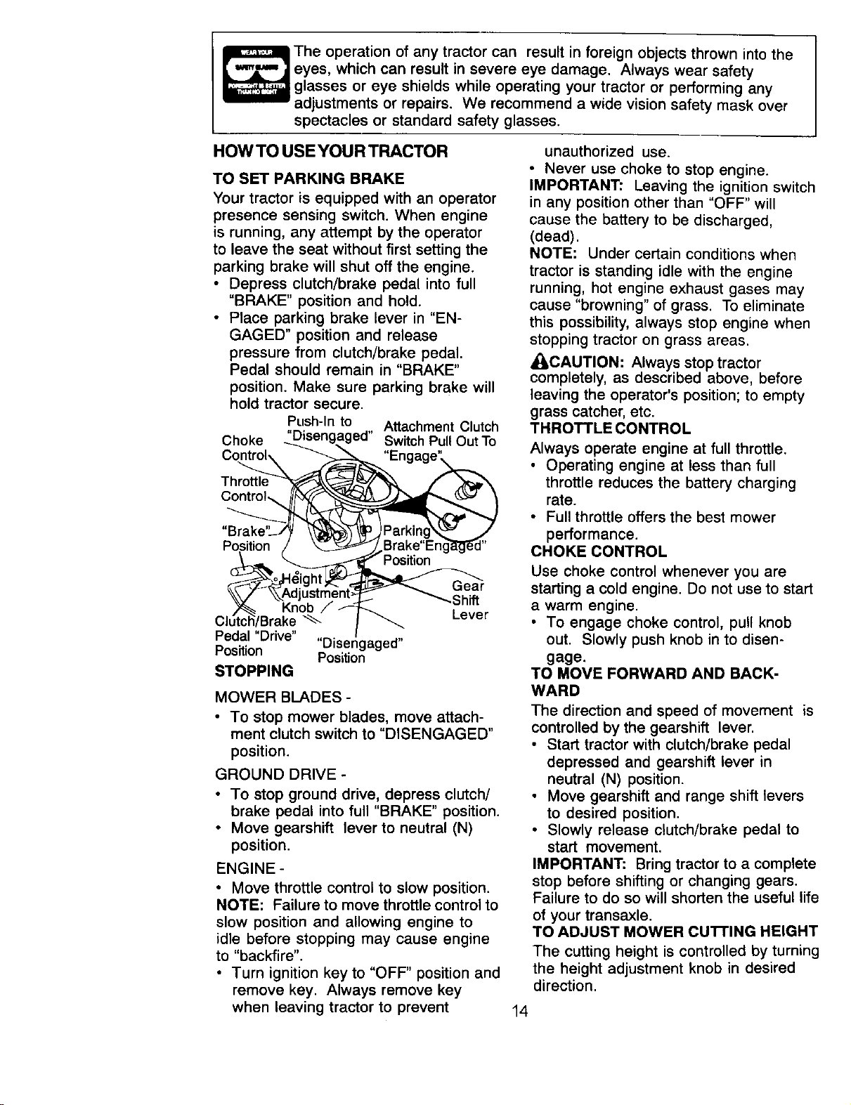
HOW TO USE YOUR TRACTOR
TO SET PARKING BRAKE
Your tractor is equipped with an operator
presence sensing switch. When engine
is running, any attempt by the operator
to leave the seat without first setting the
parking brake will shut off the engine.
• Depress clutch/brake pedal into full
"BRAKE" position and hold.
• Place parking brake lever in "EN-
GAGED" position and release
pressure from clutch/brake pedal.
Pedal should remain in "BRAKE"
position. Make sure parking brake will
hold tractor secure.
Push-In to Attachment Clutch
Choke "Disengaged" Switch Pull Out To
Position
Pedal "Drive" "Disengaged"
Position Position
STOPPING
Gear
-Sh_
Lever
MOWER BLADES -
• To stop mower blades, move attach-
ment clutch switch to "DISENGAGED"
position.
GROUND DRIVE -
• To stop ground drive, depress clutch/
brake pedal into full "BRAKE" position.
• Move gearshift lever to neutral (N)
position.
ENGINE -
• Move throttle control to slow position.
NOTE: Failure to move throttle control to
slow position and allowing engine to
idle before stopping may cause engine
to "backfire".
• Turn ignition key to "OFF" position and
remove key. Always remove key
when leaving tractor to prevent
unauthorized use.
• Never use choke to stop engine.
IMPORTANT: Leaving the ignition switch
in any position other than "OFF" will
cause the battery to be discharged,
(dead).
NOTE: Under certain conditions when
tractor is standing idle with the engine
running, hot engine exhaust gases may
cause "browning" of grass. To eliminate
this possibility, always stop engine when
stopping tractor on grass areas.
_CAUTION: Always stop tractor
completely, as described above, before
leaving the operator's position; to empty
grass catcher, etc.
THROTTLE CONTROL
Always operate engine at full throttle.
• Operating engine at less than full
throttle reduces the battery charging
rate.
• Full throttle offers the best mower
performance.
CHOKE CONTROL
Use choke control whenever you are
starting a cold engine. Do not use to start
a warm engine.
• To engage choke control, pull knob
out. Slowly push knob in to disen-
gage.
TO MOVE FORWARD AND BACK-
WARD
The direction and speed of movement is
controlled by the gearshift lever.
• Start tractor with clutch/brake pedal
depressed and gearshift lever in
neutral (N) position.
• Move gearshift and range shift levers
to desired position.
• Slowly release clutch/brake pedal to
start movement.
IMPORTANT: Bring tractor to a complete
stop before shifting or changing gears.
Failure to do so will shorten the useful life
of your transaxle.
TO ADJUST MOWER cu'n'ING HEIGHT
The cutting height is controlled by turning
the height adjustment knob in desired
direction,
14
• Turn knob clockwise (f-_) to raise
cutting height.
• Turn knob counterclockwise (v_)to
lower cutting height.
The cutting height range is approxi-
mately 1-1/2" to 4-1/2". The heights are
measured from the ground to the blade
tip with the engine not running. These
heights are approximate and may vary
depending upon soil conditions, height
of grass and types of grass being
mowed.
• The average lawn should be cut to
approximately 2-1/2 inches during the
cool season and to over 3 inches
during hot months. For healthier and
better looking lawns, mow often and
after moderate growth.
• For best cutting performance, grass
over 6 inches in height should be
mowed twice. Make the first cut
relatively high; the second to desired
height.
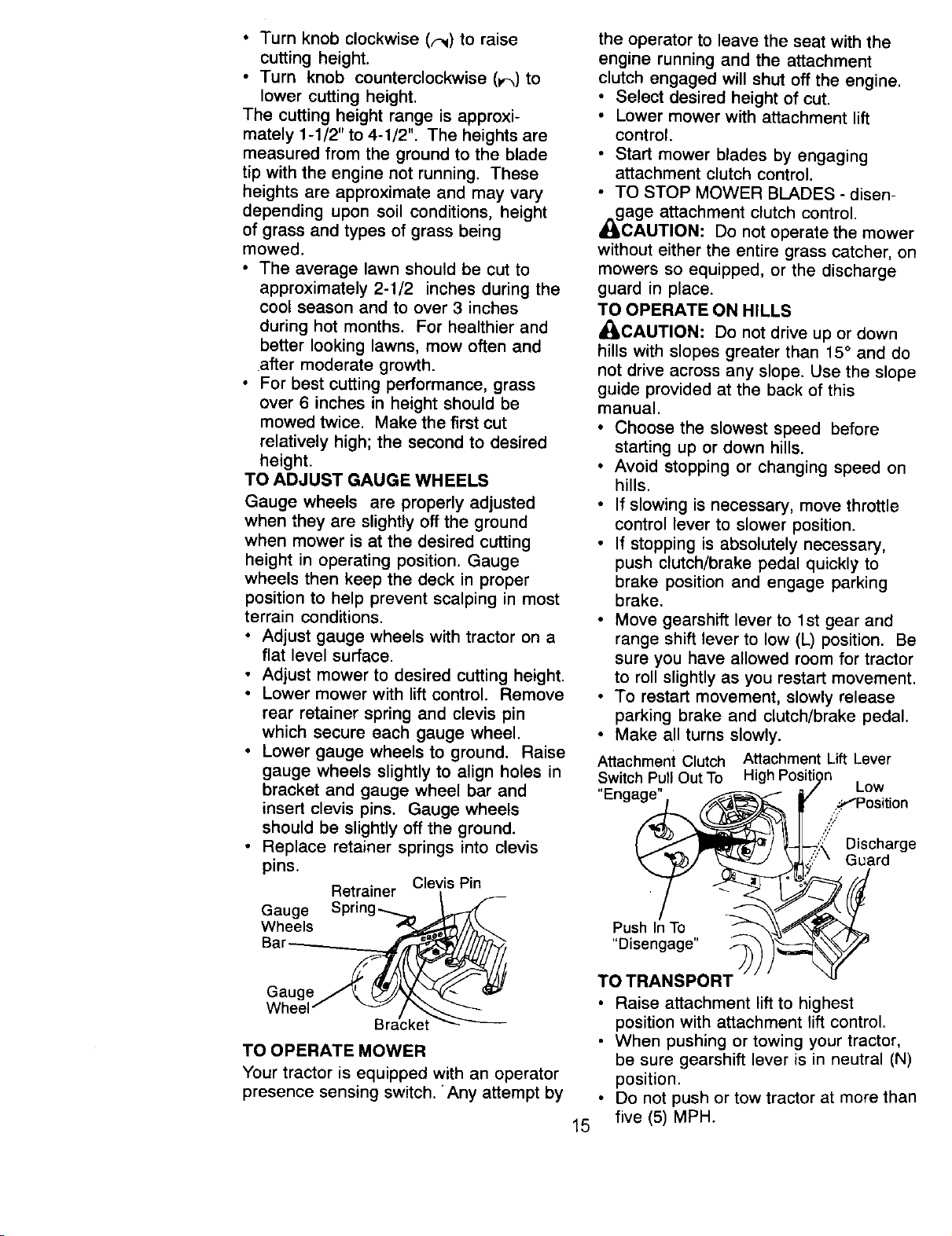
TO ADJUST GAUGE WHEELS
Gauge wheels are properly adjusted
when they are slightly oft the ground
when mower is at the desired cutting
height in operating position. Gauge
wheels then keep the deck in proper
position to help prevent scalping in most
terrain conditions.
• Adjust gauge wheels with tractor on a
flat level surface.
• Adjust mower to desired cutting height.
• Lower mower with lift control. Remove
rear retainer spring and clevis pin
which secure each gauge wheel.
• Lower gauge wheels to ground. Raise
gauge wheels slightly to align holes in
bracket and gauge wheel bar and
insert clevis pins. Gauge wheels
should be slightly off the ground.
• Replace retainer springs into clevis
pins.
Clevis Pin
Retrainer
Gauge Spring......_ _
Wheels
Bar _=_
Gauge J_. _-!/_£x"
Wheel" "_ra/cke_
TO OPERATE MOWER
Your tractor is equipped with an operator
presence sensing switch, Any attempt by
the operator to leave the seat with the
engine running and the attachment
clutch engaged will shut off the engine.
• Select desired height of cut.
• Lower mower with attachment lift
control.
• Start mower blades by engaging
attachment clutch control.
• TO STOP MOWER BLADES - disen-
A__gage attachment clutch control.
CAUTION: Do not operate the mower
without either the entire grass catcher, on
mowers so equipped, or the discharge
guard in place.
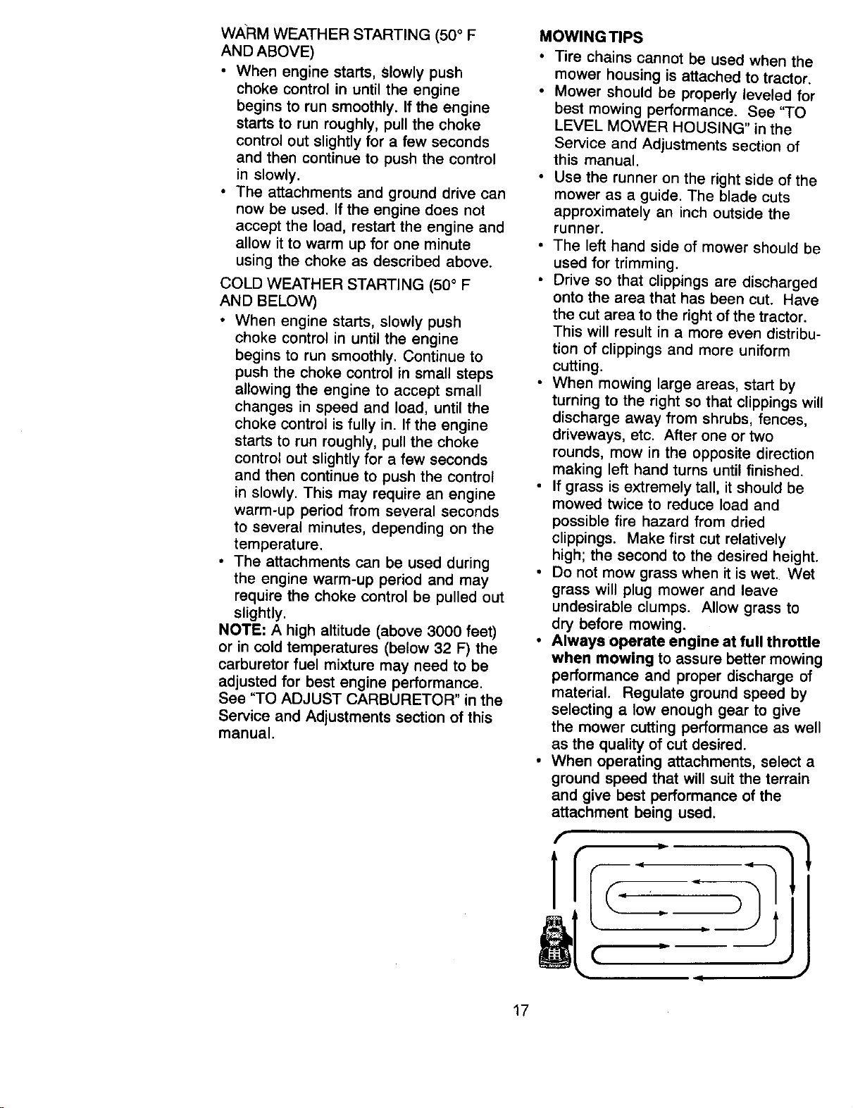
TO OPERATE ON HILLS
_IbCAUTION: Do not drive up or down
hills with slopes greater than 15 ° and do
not drive across any slope. Use the slope
guide provided at the back of this
manual.
• Choose the slowest speed before
starting up or down hills.
• Avoid stopping or changing speed on
hills.
• If slowing is necessary, move throttle
control lever to slower position.
• If stopping is absolutely necessary,
push clutch/brake pedal quickly to
brake position and engage parking
brake.
• Move gearshift lever to 1st gear and
range shift lever to low (L) position. Be
sure you have allowed room for tractor
to roll slightly as you restart movement.
• To restart movement, slowly release
parking brake and clutch/brake pedal.
• Make all turns slowly.
Attachment Clutch Attachment Lift Lever
Switch P,ul_Out 3"o High Posit_on Low
Enga_ _/ ..:!.;_,"Position
( _'f_J ___.!_ Discharge
'_/ _ _[,:_" Guard
Push In TO ,, _'_d _-_,T_'._,/_.
• Raise attachment lift to highest
position with attachment lift control.
• When pushing or towing your tractor,
be sure gearshift lever is in neutral (N)
position.
• Do not push or tow tractor at more than
15 five (5) MPH.

NOTE:Toprotecthoodfromdamage
whentransportingyourtractoron a truck
or a trailer, be sure hood is closed and
secured to tractor. Use an appropriate
means of tying hood to tractor (rope,
cord, etc.).
TOWING CARTS AND OTHER AT-
TACHMENTS
Tow only the attachments that are
recommended by and comply with
specifications of the manufacturer of your
tractor. Use common sense when towing.
Too heavy of a load, while on a slope, is
dangerous. Tires can lose traction with
the ground and cause you to lose control
of your tractor.
BEFORE STARTING THE ENGINE
CHECK ENGINE OIL LEVEL
• The engine in your tractor has been
shipped, from the factory, already filled
with summer weight oil.
• Check engine oil with tractor on level
ground.
• Unthread and remove oil fill cap/
dipstick; wipe oil off. Reinsert the
dipstick into the tube and rest oil fill
cap on the tube. Do not thread the cap
onto the tube. Remove and read oil
level. If necessary, add oil until
"FULL" mark on dipstick is reached.
Do not overfill.
• For cold weather operation you should
change oil for easier starting (See "OIL
VISCOSITY CHART' in the Mainte-
nance section of this manual).
• To change engine oil, see the Mainte-
nance section in this manual.
ADD GASOLINE
• Fill fuel tank. Use fresh, clean, regular
unleaded gasoline with a minimum of
87 octane. (Use of leaded gasoline
will increase carbon and lead oxide
deposits and reduce valve life). Do
not mix oil with gasoline. Purchase
fuel in quantities that can be used
within 30 days to assure fuel fresh-
ness.
IMPORTANT: When operating in
temperatures below 32°F(0°C), use
fresh, clean winter grade gasoline to
help insure good cold weather starting.
_WARNING: Experience indicates that
alcohol blended fuels (called gasohol or
using ethanol or methanol) can attract
moisture which leads to separation and
formation of acids during storage. Acidic
gas can damage the fuel system of an
engine while in storage. To avoid engine
problems, the fuel system should be
emptied before storage of 30 days or
longer. Drain the gas tank, start the
engine and let it run until the fuel lines
and carburetor are empty. Use fresh fuel
next season. See Storage Instructions
for additional information. Never use
engine or carburetor cleaner products in
the fuel tank or permanent damage may
_ICcur"
AUTION" Fill to bottom of gas tank
filler neck. Do not overfill. Wipe off any
spilled oil or fuel. Do not store, spill or
use gasoline near an open flame.
TO START ENGINE
When starting the engine for the first time
or if the engine has run out of fuel, it will
take extra cranking time to move fuel
from the tank to the engine.
• Sit on seat in operating position,
depress clutch/brake pedal and set
parking brake.
• Place gear shift lever in neutral (N)
position.
• Move attachment clutch to "DISEN-
GAGED" position.
• Move throttle control to fast position
• Pull choke control out for a cold
engine start attempt. For a warm
engine start attempt the choke control
may not be needed.
NOTE: Before starting, read the warm
and cold starting procedures below.
• Insert key into ignition and turn key
clockwise to "START' position and
release key as soon as engine starts.
Do not run starter continuously for
more than fifteen seconds per minute.
If the engine does not start after
several attempts, push choke control
in, wait a few minutes and try again. If
engine still does not start, pull the
choke control out and retry.
16
WARM WEATHER STARTING (50 ° F
AND ABOVE)
• When engine starts, Slowly push
choke control in until the engine
begins to run smoothly. If the engine
starts to run roughly, pull the choke
control out slightly for a few seconds
and then continue to push the control
in slowly.
• The attachments and ground drive can
now be used. If the engine does not
accept the load, restart the engine and
allow it to warm up for one minute
using the choke as described above.
COLD WEATHER STARTING (50 ° F
AND BELOW)
• When engine starts, slowly push
choke control in until the engine
begins to run smoothly. Continue to
push the choke control in small steps
allowing the engine to accept small
changes in speed and load, until the
choke control is fully in. If the engine
starts to run roughly, pull the choke
control out slightly for a few seconds
and then continue to push the control
in slowly. This may require an engine
warm-up period from several seconds
to several minutes, depending on the
temperature.
• The attachments can be used during
the engine warm-up period and may
require the choke control be pulled out
slightly.
NOTE: A high altitude (above 3000 feet)
or in cold temperatures (below 32 F) the
carburetor fuel mixture may need to be
adjusted for best engine performance.
See "TO ADJUST CARBURETOR" in the
Service and Adjustments section of this
manual.
MOWING TIPS
• Tire chains cannot be used when the
mower housing is attached to tractor.
• Mower should be properly leveled for
best mowing performance. See "TO
LEVEL MOWER HOUSING" in the
Service and Adjustments section of
this manual.
• Use the runner on the right side of the
mower as a guide. The blade cuts
approximately an inch outside the
runner.
• The left hand side of mower should be
used for trimming.
• Drive so that clippings are discharged
onto the area that has been cut. Have
the cut area to the right of the tractor.
This will result in a more even distribu-
tion of clippings and more uniform
cutting.
• When mowing large areas, start by
turning to the right so that clippings will
discharge away from shrubs, fences,
driveways, etc. After one or two
rounds, mow in the opposite direction
making left hand turns until finished.
• If grass is extremely tall, it should be
mowed twice to reduce load and
possible fire hazard from dried
clippings. Make first cut relatively
high; the second to the desired height.
• Do not mow grass when it is wet. Wet
grass will plug mower and leave
undesirable clumps. Allow grass to
dry before mowing.
• Always operate engine at full throttle
when mowing to assure better mowing
performance and proper discharge of
material. Regulate ground speed by
selecting a low enough gear to give
the mower cutting performance as well
as the quality of cut desired.
• When operating attachments, select a
ground speed that will suit the terrain
and give best performance of the
attachment being used,
17
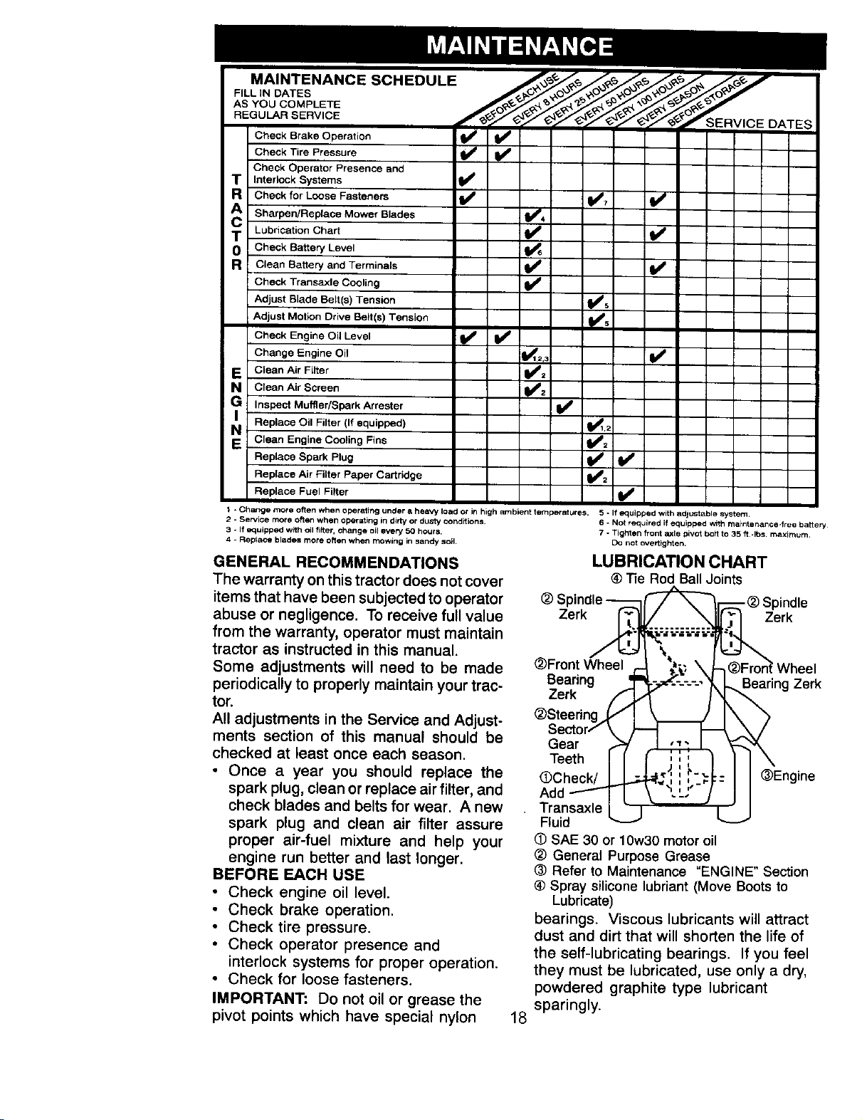
MAINTENANCE SCHEDULE ./___/_o_/,_o_ _o_o_y_
FILL IN DATES
REGULAR
Che_k Brake Operation _
Check Tire Pressure
Cheek Operator Presence and
T Interlock Systems
R Check for Loose Fasteners _ _7
cA Sharpen/Replace Mower Blades _4
T LubriCation Chart
0 Che_k Battery Level
R Clean Battery and Tetmlnals
Check Transaxle Cooling
Adjust Blade Belt(s) Tension _s
Adjust Motk_n Drive Be_t(s) Tension
Check Engine Oil Level t_
Change Engine Oil _=,_
ECleanAi'Fil'e' _f#:
a Clean Air Screen
Inspect Muffler/Spark Arrester ll_
Replace Oil FB_er (li equipped) _1,2 I
N Clean Engine Cooling Fins _2
Replace Spark Plug _ _1_
Replace Air Fi_terP_per Cartridge t##2 I
Replace Fuel Filter
1 - Change mote often when operating under a heaVy load or in high F=mbient temperatures. 5 - If equipped with adfut_table system
2 - Service mote often when operating in dirty or dusty conditions,
3 - If equipped with oil fi_er, change oil every 50 hours,
4 - Replace blades mote often when mowing in sandy soil
GENERAL RECOMMENDATIONS
The warranty on this tractor does not cover
items that have been subjected to operator
abuse or negligence. To receive full value
from the warranty, operator must maintain
tractor as instructed in this manual.
Some adjustments will need to be made
periodically to properly maintain your trac-
tor.
All adjustments in the Service and Adjust-
ments section of this manual should be
checked at least once each season.
• Once a year you should replace the
spark plug, clean or replace air filter, and
check blades and belts for wear. A new
spark plug and clean air filter assure
proper air-fuel mixture and help your
engine run better and last longer.
BEFORE EACH USE
• Check engine oil level.
• Check brake operation.
• Check tire pressure.
• Check operator presence and
interlock systems for proper operation.
. Check for loose fasteners.
IMPORTANT: Do not oil or grease the
pivot points which have special nylon
18
6 - Not required if equipped With malntenance-free Caile _/
7 - _ighten front _le pivot bo_t to 35 ft -Ibs maximum
Do not overtighten.
LUBRICATION CHART
® -_e Rod BallJoints
(_ Spindle _ _"_--'_ _) Spindle
Zerk _[_ i =_erk
_)FrontWheel , -I _ \ J-_Fron_Wheel
Bearing _'t \-_---=-----_ _ Bearing Zerk
Zerk _j " I _L
_)Steedng_ _ J_
Sector/ \ ) -! _ ._._
Gear _ _ _-_
Teeth II :!: I II \
( Check/IL I I 'Engine
_, ,v
Add--ty7 j,.L."J I I
, Transaxlel " I " J
Fluid _--" v
SAE 30 or 10w30 motor oil
(_ General Purpose Grease
(_ Refer to Maintenance "ENGINE" Section
® Spray silicone lubriant (Move Boots to
Lubricate)
bearings. Viscous lubricants will attract
dust and dirt that will shorten the life of
the self-lubricating bearings. If you feel
they must be lubricated, use only a dry,
powdered graphite type lubricant
sparingly.
TRACTOR
Always observe safety rules when
performing any maintenance.
BRAKE OPERATION
If tractor requires more than six (6) feet
stopping distance at high speed in
highest gear, then brake must be
adjusted. (See "TO ADJUST BRAKE" in
the Service and Adjustments section of
this manual).
TIRES
• Maintain proper air pressure in all tires
(See "PRODUCT SPECIFICATIONS"
section of this manual).
• Keep tires free of gasoline, oil, or
insect control chemicals which can
harm rubber.
• Avoid stumps, stones, deep ruts, sharp
objects and other hazards that may
cause tire damage.
NOTE: To seal tire punctures and
prevent flat tires due to slow leaks, tire
sealant may be purchased from your
local parts dealer. Tire sealant also
prevents tire dry rot and corrosion.
OPERATOR PRESENCE SYSTEM
Be sure operator presence and interlock
systems are working properly. If your
tractor does not function as described,
repair the problem immediately.
• The engine should not start unless the
clutch/brake pedal is fully depressed
and attachement clutch control is in
the disengaged position.
• When the engine is running, any
attempt by the operator to leave the
seat without first setting the parking
brake should shut off the engine.
• When the engine is running and the
attachment clutch is engaged, any
attempt by the operator to leave the
seat should shut off the engine.
• The attachment clutch should never
operate unless the operator is in the
seat.
BLADE CARE
For best results mower blades must be
kept sharp. Replace bent or damaged
blades.
BLADE REMOVAL
• Raise mower to highest position to
allow access to blades.
• Remove hex bolt, lock washer and flat
washer securing blade.
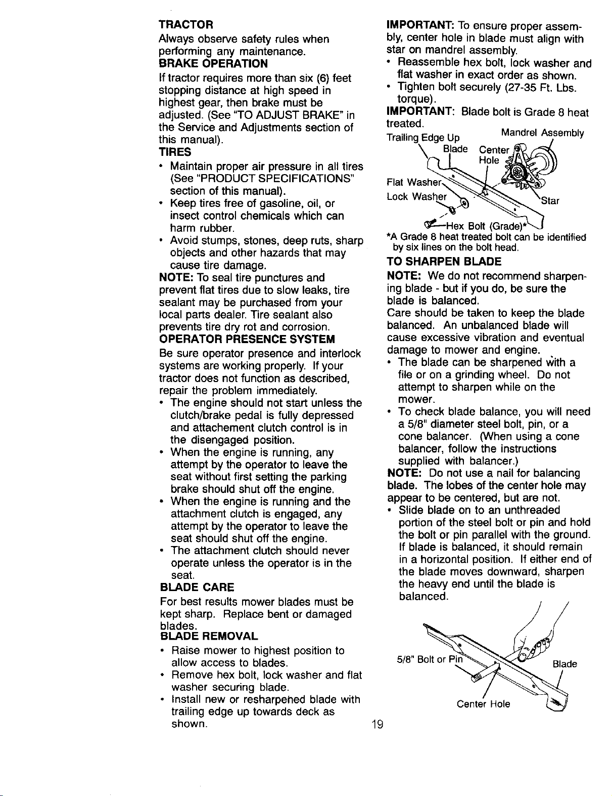
• Install new or resharpehed blade with
trailing edge up towards deck as
shown.
IMPORTANT: To ensure proper assem-
bly, center hole in blade must align with
star on mandrel assembly.
• Reassemble hex bolt, lock washer and
flat washer in exact order as shown.
• Tighten bolt securely (27-35 Ft. Lbs.
torque).
IMPORTANT: Blade bolt is Grade 8 heat
treated.
Trailing Edge Up Mandrel Assembly
\ Blade Center _
Flat Washer_.__
•
_P----Hex Bolt (Grade)*L--.J
•A Grade 8 heat treated bolt can be identified
by six lines on the bolt head.
TO SHARPEN BLADE
NOTE: We do not recommend sharpen-
ing blade - but if you do, be sure the
blade is balanced.
Care should be taken to keep the blade
balanced. An unbalanced blade will
cause excessive vibration and eventual
damage to mower and engine.
• The blade can be sharpened with a
file or on a grinding wheel. Do not
attempt to sharpen while on the
mower.
• To check blade balance, you will need
a 5/8" diameter steel bolt, pin, or a
cone balancer. (When using a cone
balancer, follow the instructions
supplied with balancer.)
NOTE: Do not use a nail for balancing
blade. The lobes of the center hole may
appear to be centered, but are not.
• Slide blade on to an unthreaded
portion of the steel bolt or pin and hold
the bolt or pin parallel with the ground.
If blade is balanced, it should remain
in a horizontal position. If either end of
the blade moves downward, sharpen
the heavy end until the blade is
balanced.
518" e
Center Hole
19
BATTERY
Your tractor has a battery charging
system which is sufficient for normal use.
However, periodic charging of the battery
with an automotive charger will extend
its life.
• Keep battery and terminals clean.
• Keep battery bolts tight.
• Keep small vent holes open.
• Recharge at 6-10 amperes for 1 hour.
NOTE: The original equipment battery on
your tractor is maintenance free. Do not
attempt to open or remove caps or
covers. Adding or checking level of
electrolyte is not necessary.
TO CLEAN BATTERY AND TERMINALS
Corrosion and did on the battery and
terminals can cause the battery to "leak"
power.
• Remove terminal guard.
• Disconnect BLACK battery cable first
then RED battery cable and remove
battery from tractor.
• Rinse the battery with plain water and
dry.
• Clean terminals and battery cable
ends with wire brush until bright.
• Coat terminals with grease or petro-
leum jelly.
• Reinstall battery (See "REPLACING
BATTERY" in the SERVICE AND
ADJUSTMENTS section of this
manual).
V-BELTS
Check V-belts for deterioration and wear
after 100 hours of operation and replace
if necessary. The belts are not adjustable.
Replace belts if they begin to slip from
wear.
TRANSAXLECOOLING
Keep transaxle free from build-up of dirt
and chaff which can restrict cooling.
CHECK TRANSAXLE OIL LEVEL
• Block up rear axle securely.
• Remove left rear wheel by removing
hub bolts.
• Remove filler plug from transaxle. Oil
level must be even with plug threads.
If necessary, fill with SAE 30 motor oil,
API SF, SG or SH. Replace filler plug.
• Reassemble wheel to hub.
_Transaxle Filler
'_, _ Plug
ENGINE
LUBRICATION
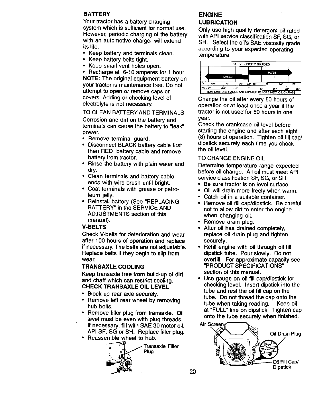
Only use high quality detergent oil rated
with API service classification SF, SG, or
SH. Select the oil's SAE viscosity grade
according to your expected operating
temperature.
SAE VISCOSITY GRADES
"c .30-
.1o- o* io- 20-
TEMPERA_JRE RANGE ANTICIPATED BEFORE NEXT OIL CHANGE
Change the oil after every 50 hours of
operation or at least once a year if the
tractor is not used for 50 hours in one
year.
Check the crankcase oil level before
starting the engine and after each eight
(8) hours of operation. Tighten oil fill cap/
dipstick securely each time you check
the oil level.
TO CHANGE ENGINE OIL
Determine temperature range expected
before oil change. All oil must meet API
service classification SF, SG, or SH.
• Be sure tractor is on level surface.
• Oil will drain more freely when warm.
• Catch oil in a suitable container.
• Remove oil fill cap/dipstick. Be careful
not to allow dirt to enter the engine
when changing oil.
• Remove drain plug.
• After oil has drained completely,
replace oil drain plug and tighten
securely.
• Refill engine with oil through oil fill
dipstick tube. Pour slowly. Do not
overfill. For approximate capacity see
"PRODUCT SPECIFICATIONS"
section of this manual.
• Use gauge on oil fill cap/dipstick for
checking level. Insert dipstick into the
tube and rest the oil fill cap on the
tube. Do not thread the cap onto the
tube when taking reading. Keep oil
at "FULL" line on dipstick. Tighten cap
onto the tube securely when finished.
Air Screen
\
Oil Drain Plug
2O
Dipstick
CLEAN AIR SCREEN
Air screen must be kept free of dirt and
chaff to prevent engine damage from
overheating. Clean with a wire brush or
compressed air to remove dirt and
stubborn dried gum fibers.
CLEAN AIR INTAKE/COOLING AREAS
To insure proper cooling, make sure the
grass screen, cooling fins, and other
external surfaces of the engine are kept
clean at all times.
Every 100 hours of operation (more often
under extremely dusty, dirty conditions),
remove the blower housing and other
cooling shrouds. Clean the cooling fins
and external surfaces as necessary.
Make sure the cooling shrouds are
reinstalled.
NOTE: Operating the engine with a
blocked grass screen, dirty or plugged
cooling fins, and/or cooling shrouds
removed will cause engine damage due
to overheating.
AIR FILTER
Your engine will not run properly using a
dirty air filter. Clean the foam pre-cleaner
after every 25 hours of operation or
every season. Service paper cartridge
every 100 hours of operation or every
season, whichever occurs first.
Service air cleaner more often under
dusty conditions.
• Loosen knob and remove cover.
TO SERVICE PRE-CLEANER
• Slide foam pre-cleaner off cartridge.
• Wash it in liquid detergent and water.
• Squeeze it dry in a clean cloth. Allow
it to dry.
• Saturate it in engine oil. Wrap it in
clean, absorbent cloth and squeeze to
remove excess oil.
TO SERVICE CARTRIDGE
• Replace a dirty, bent, or damaged
cartridge.
NOTE: Do not wash the paper cartridge
or use pressurized air, as this will
damage the cartridge.
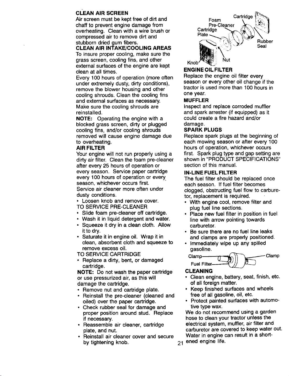
• Remove nut and cartridge plate.
• Reinstall the pre-cleaner (cleaned and
oiled) over the paper cartridge.
• Check rubber seal for damage and
proper position around stud. Replace
if necessary.
• Reassemble air cleaner, cartridge
plate, and nut.
• Reinstall air cleaner cover and secure
by tightening knob.
Cartridge
Foam
Pre-Cleaner
Cartridge
Plate
Rubber
Seal
Knob : Nut
ENGINE OIL FILTER
Replace the engine oil filter every
season or every other oil change if the
tractor is used more than 100 hours in
one year.
MUFFLER
Inspect and replace corroded muffler
and spark arrester (if equipped) as it
could create a fire hazard and/or
damage.
SPARK PLUGS
Replace spark plugs at the beginning of
each mowing season or after every 100
hours of operation, whichever occurs
first. Spark plug type and gap setting are
shown in "PRODUCT SPECIFICATIONS"
section of this manual.
IN-LINE FUEL FILTER
The fuel filter should be replaced once
each season. If fuel filter becomes
clogged, obstructing fuel flow to carbure-
tor, replacement is required.
• With engine cool, remove filter and
plug fuel line sections.
• Place new fuel filter in position in fuel
line with arrow pointing towards
carburetor.
• Be sure there are no fuel line leaks
and clamps are properly positioned.
• Immediately wipe up any spilled
gasoline.
Clamp_ Clamp
Fuel Filter_j L_J
CLEANING
• Clean engine, battery, seat, finish, etc.
of all foreign matter.
• Keep finished surfaces and wheels
free of all gasoline, oil, etc.
• Protect painted surfaces with automo-
tive type wax.
We do not recommend using a garden
hose to clean your tractor unless the
electrical system, muffler, air filter and
carburetor are covered to keep water out.
Water in engine can result in a short-
21 ened engine life.
_CAUTION: Before performing any service or adjustments:
• Depress clutch/brake pedal fully and set parking brake.
• Place gearshift lever in neutral (N) position.
• Place attachment clutch in "DISENGAGED" position.
• Turn ignition key "OFF" and remove key.
• Make sure the blades and all moving parts have completely stopped.
• Disconnect spark plug wire from spark plug and place wire where it cannot come
in contact with plug.
TRACTOR
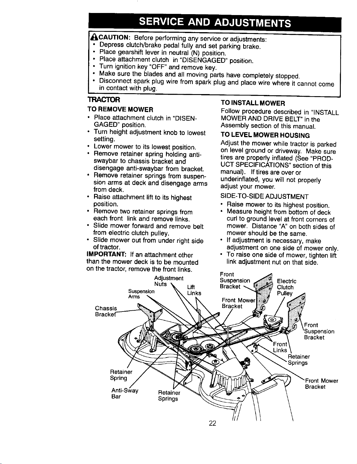
TO REMOVE MOWER
• Place attachment clutch in "DISEN-
GAGED" position.
• Turn height adjustment knob to lowest
setting.
• Lower mower to its lowest position.
• Remove retainer spring holding anti-
swaybar to chassis bracket and
disengage anti-swaybar from bracket.
• Remove retainer springs from suspen-
sion arms at deck and disengage arms
from deck.
• Raise attachment lift to its highest
position.
• Remove two retainer springs from
each front link and remove links.
• Slide mower forward and remove belt
from electric clutch pulley.
• Slide mower out from under right side
of tractor.
IMPORTANT: If an attachment other
than the mower deck is to be mounted
on the tractor, remove the front links.
Adjustment
Nuts Lift
Suspension Links
Arms
TO INSTALL MOWER
Follow procedure described in "INSTALL
MOWER AND DRIVE BELT" in the
Assembly section of this manual.
TO LEVEL MOWER HOUSING
Adjust the mower while tractor is parked
on level ground or driveway. Make sure
tires are properly inflated (See "PROD-
UCT SPECIFICATIONS" section of this
manual). If tires are over or
underinflated, you will not properly
adjust your mower.
SIDE-TO-SIDE ADJUSTMENT
• Raise mower to its highest position.
• Measure height from bottom of deck
curl to ground level at front corners of
mower. Distance "A" on both sides of
mower should be the same.
• If adjustment is necessary, make
adjustment on one side of mower only.
• To raise one side of mower, tighten lift
link adjustment nut on that side.
Front
Suspension Electric
Bracket Clutch
Pulley
Front
Chassis
Front
pension
Bracket
Retainer
Retainer
Spring
Anti-S_ay
Bar
Retainer
Springs
Mower
Bracket
22
• To lower one side of mower, loosen lift
link adjustment nut on that side.
NOTE: Each full turn of adjustment nut
will change mower height about 3/16".
• Recheck measurements after adjust-
ing.
Bottom _ Bottom edge of
edge of _ ,L _ . _ mower
mower t(_ IA_=_ _\1_1 I to
ground.J---______o_/g rOund
roun,UneT""T-
FRONT-TO-BACKADJUSTMENT
IMPORTANT: DECK MUST BE LEVEL
SIDE-TO-SIDE. If the following front-to-
back adjustment is necessary, be sure to
adjust both front links equally so mower
will stay level side-to-side.
To obtain the best cutting results, the
mower housing should be adjusted so
the front is approximately 1/8" to 1/2"
lower than the rear when the mower is in
its highest position.
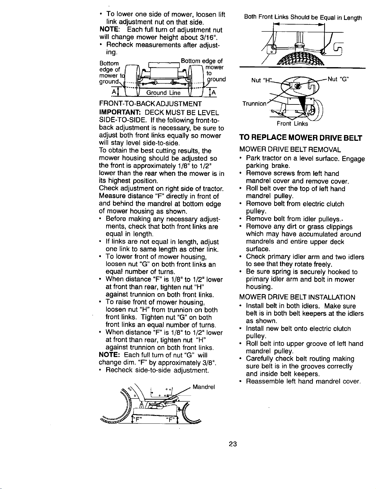
Check adjustment on right side of tractor.
Measure distance "F" directly in front of
and behind the mandrel at bottom edge
of mower housing as shown.
• Before making any necessary adjust-
ments, check that both front links are
equal in length.
• If links are not equal in length, adjust
one link to same length as other link.
• To lower front of mower housing,
loosen nut "G" on both front links an
equal number of turns.
• When distance "F" is 1/8" to 1/2" lower
at front than rear, tighten nut "H"
against trunnion on both front links.
• To raise front of mower housing,
loosen nut "H" from trunnion on both
front links. Tighten nut "G" on both
front links an equal number of turns.
• When distance "F" is 1/8" to 1/2" lower
at front than rear, tighten nut "H"
against trunnion on both front links.
NOTE: Each full turn of nut "G" will
change dim. "F" by approximately 3/8".
• Recheck side-to-side adjustment.
Both Front Links Should be Equal in Length
Nut
Front Links
TO REPLACE MOWER DRIVE BELT
MOWER DRIVE BELT REMOVAL
• Park tractor on a level surface. Engage
parking brake.
• Remove screws from left hand
mandrel cover and remove cover.
• Roll belt over the top of left hand
mandrel pulley.
• Remove belt from electric clutch
pulley.
• Remove belt from idler pulleys..
• Remove any dirt or grass clippings
which may have accumulated around
mandrels and entire upper deck
surface.
• Check primary idler arm and two idlers
to see that they rotate freely.
• Be sure spring is securely hooked to
primary idler arm and bolt in mower
housing.
MOWER DRIVE BELT INSTALLATION
• Install belt in both idlers. Make sure
belt is in both belt keepers at the idlers
as shown.
• Install new belt onto electric clutch
pulley.
• Roll belt into upper groove of left hand
mandrel pulley.
• Carefully check belt routing making
sure belt is in the grooves correctly
and inside belt keepers.
• Reassemble left hand mandrel cover.
23
Bcrews
Left Hand Idler Electric
Mandrel Pulleys Clutch
Primary
tdler Arm
Hand
Mandrel
Drive Belt
Belt
Keepers
Boltin
Housing
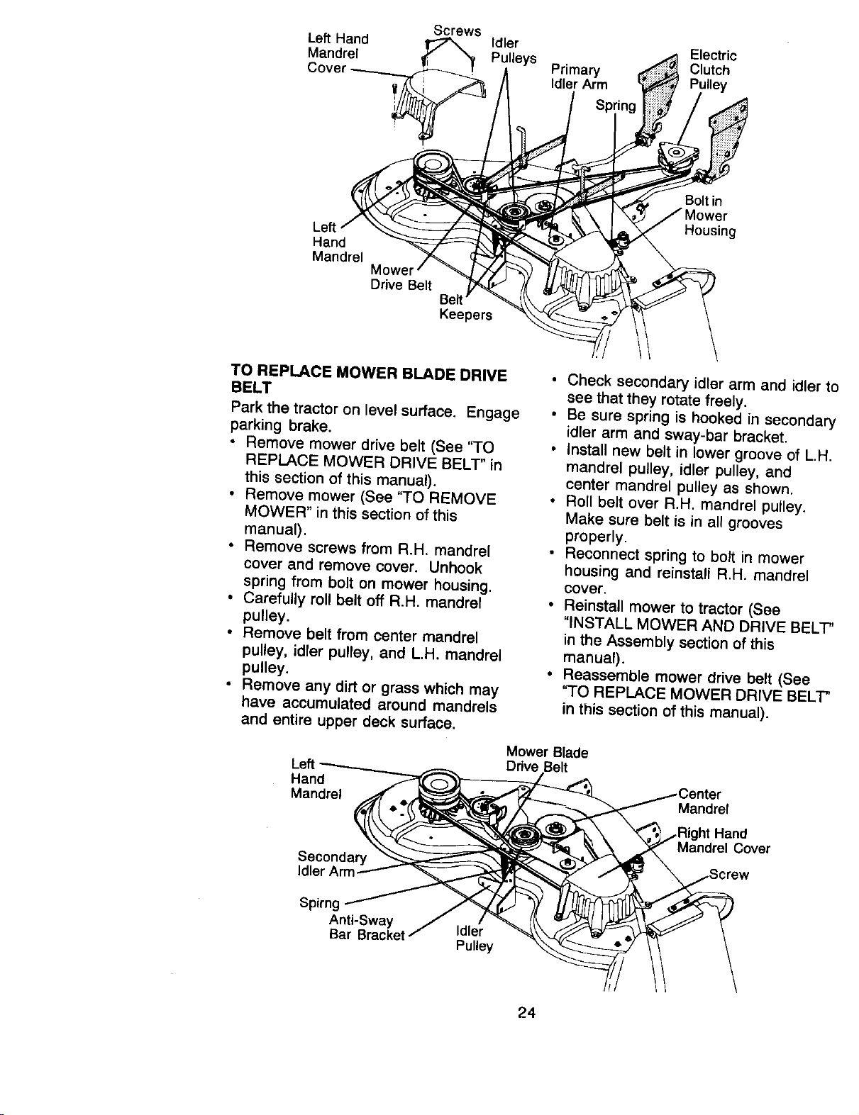
TO REPLACE MOWER BLADE DRIVE
BELT
Park the tractor on level surface. Engage
parking brake.
• Remove mower drive belt (See "TO
REPLACE MOWER DRIVE BELT" in
this section of this manual).
• Remove mower (See "TO REMOVE
MOWER" in this section of this
manual).
• Remove screws from R.H. mandrel
cover and remove cover. Unhook
spring from bolt on mower housing.
• Carefully roll belt off R.H. mandrel
pulley.
• Remove belt from center mandrel
pulley, idler pulley, and L.H. mandrel
pulley.
• Remove any dirt or grass which may
have accumulated around mandrels
and entire upper deck surface.
Hand
Mandrel
Secondary
• Check secondary idler arm and idler tc
see that they rotate freely.
• Be sure spring is hooked in secondary
idler arm and sway-bar bracket.
• Install new belt in lower groove of L.H.
mandrel pulley, idler pulley, and
center mandrel pulley as shown.
• Roll belt over R.H. mandrel pulley.
Make sure belt is in all grooves
properly.
• Reconnect spring to bolt in mower
housing and reinstall R.H. mandrel
cover.
• Reinstall mower to tractor (See
"INSTALL MOWER AND DRIVE BELT'
in the Assembly section of this
manual).
• Reassemble mower drive belt (See
'_O REPLACE MOWER DRIVE BELT'
in this section of this manual).
Mower Blade
Drive Belt
Mandrel
,Right Hand
Mandrel Cover
Spirng
Anti-Sway
Bar Bracket Idler
Pulley
24
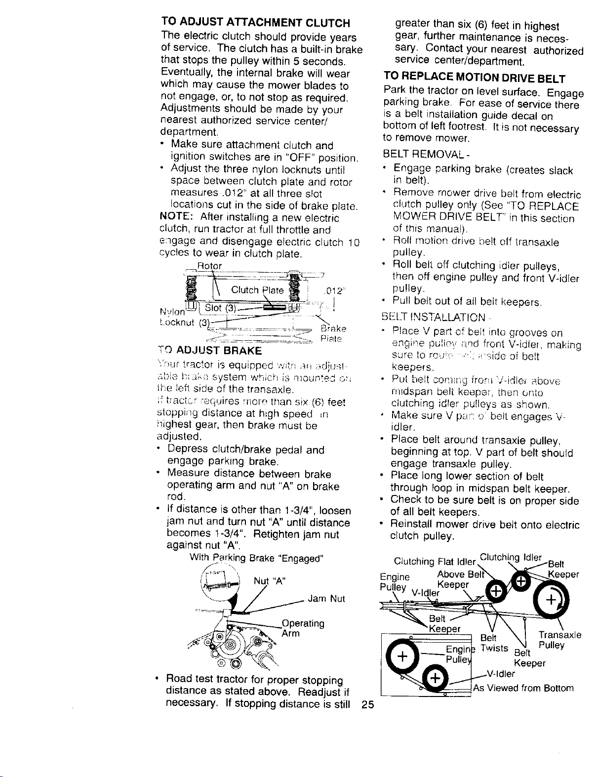
TO ADJUST ATTACHMENT CLUTCH
The electric clutch should provide years
of service. The clutch has a built-in brake
that stops the pulley within 5 seconds.
Eventually, the internal brake will wear
which may cause the mower blades to
not engage, or, to not stop as required.
Adjustments should be made by your
nearest authorized service center/
department.
• Make sure attachment clutch and
ignition switches are in "OFF" position.
• Adjust the three nylon Iocknuts until
space between clutch plate and rotor
measures .012" at all three slot
locations cut in the side of brake plate.
NOTE: After installing a new electric
clutch, run tractor at full throttle and
engage and disengage electric clutch !0
cycles to wear in clutch plate.
Rotor
.='_: .... -.-z _-_z -3 ,
,
_.ocknu, (3_-C'-_-'1 .... ;--. Brake
TO ADJUST BRAKE
"%ur tractor is equipped with _n _dit.Jst
,;['.,io i:.._:_ke system wh;ch is mounted oh
1he left side of the transax!e.
if bactcr "equires morq than six (6) feet
stopping distance at high speed ,n
i_ighest gear, then brake must be
adjusted.
* Depress clutch/brake pedal and
engage parking brake.
. Measure distance between brake
operating arm and nut "A" on brake
rod.
• If distance is other than 1-3/4", loosen
jam nut and turn nut "A" until distance
becomes 1-3/4". Retighten jam nut
against nut "A".
With Parking Brake "Engaged"
._ Jam Nut
4 _Or I:erating
• Road test tractor for proper stopping
distance as stated above. Readjust if
necessary. If stopping distance is still
greater than six (6) feet in highest
gear, further maintenance is neces-
sary. Contact your nearest authorizec
service center/department.
TO REPLACE MOTION DRIVE BELT
Park the tractor on level surface. Engage
parking brake. For ease of service there
is a belt installation guide decal on
bottom of left footrest. It is not necessary
to remove mower.
BELT REMOVAL-
• Engage parking brake (creates slack
in belt).
• Remove mower drive belt from electric
clutch pulley on!y (See "TO REPLACE
MOWER DRIVE BELT" in this section
of this manual).
• Rolt motion drive he!t off transaxle
pulley.
• Roll belt off clutching id{er pulleys,
then off engine pulley and front V-idler
pulley.
, Pull belt out of all belt keepers.
BELT INSTALLATION .
- Place V part, of belt into grooves on
engine pu!ie'? and front V-idle_, making
sure to ro_' ,',:: ;_side of belt
keepers.
Put belt com_r,g from V-idle, above
mldspan belt keeper, then onto
clutching idler pulleys as shown.
Make sure V par e belt engages V-
idler.
Place belt around transaxle pulley,
beginning at top. V part of belt should
engage transaxle pulley.
• Place iong lower section of belt
through loop in midspan belt keeper.
• Check to be sure belt is on proper side
of all belt keepers.
• Reinstall mower drive belt onto electric
clutch pulley.
Clutching Flat Idlerclutchin'
Above Belt\
Engine Kee
Pulley V-Idler
per
25
Engir
Belt Transaxle
Pulley
Twists Belt
Keeper
As Viewed from Bottom
IMPORTANT: Check brake adjustment.
TO ADJUST STEERING WHEEL
ALIGNMENT
If steering wheel crossbars are not
horizontal (left to right) when wheels are
positioned straight forward, remove
steering wheel and reassemble per
instructions in the Assembly section of
this manual.
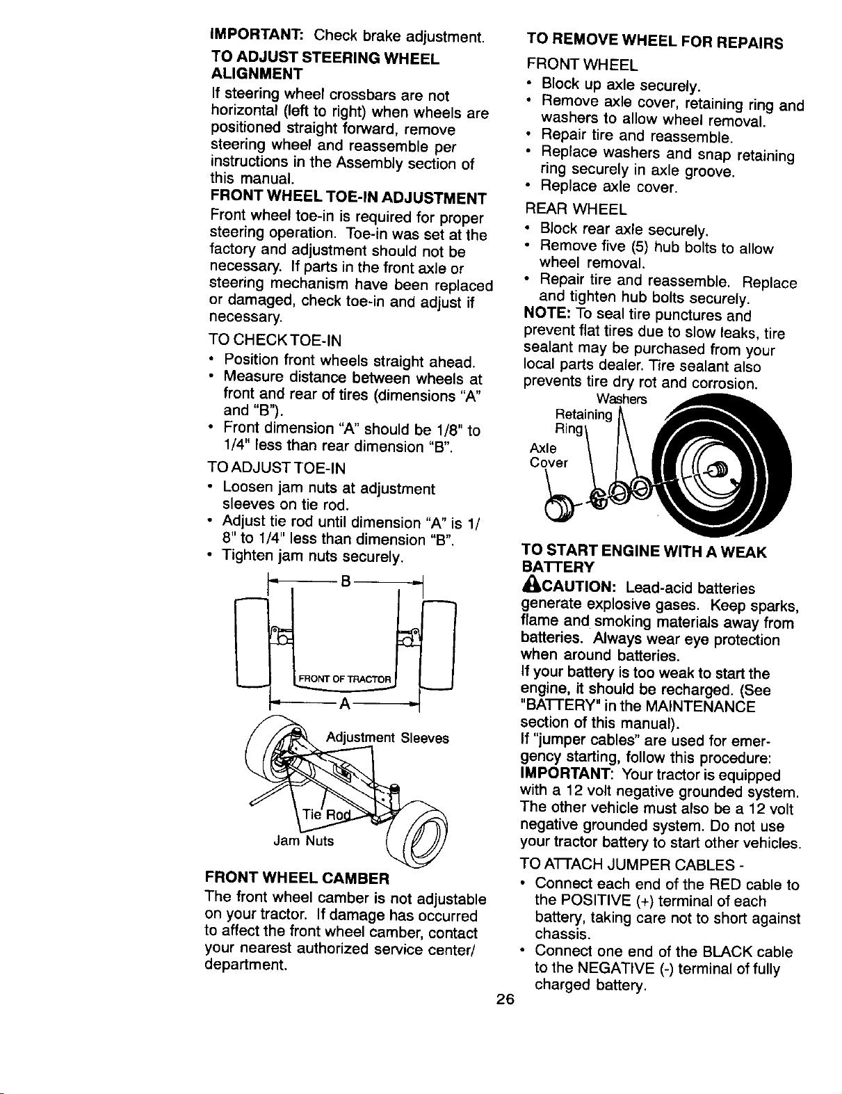
FRONT WHEEL TOE-IN ADJUSTMENT
Front wheel toe-in is required for proper
steering operation. Toe-in was set at the
factory and adjustment should not be
necessary, If parts in the front axle or
steering mechanism have been replaced
or damaged, check toe-in and adjust if
necessary.
TO CHECKTOE-IN
• Position front wheels straight ahead.
• Measure distance between wheels at
front and rear of tires (dimensions "A"
and "B").
• Front dimension "A" should be 1/8" to
1/4" less than rear dimension "B".
TO ADJUST TOE-IN
• Loosen jam nuts at adjustment
sleeves on tie rod.
• Adjust tie rod until dimension "A" is 1/
8" to 1/4" less than dimension "B".
• Tighten jam nuts securely.
Adjustment Sleeves
Jam Nuts
FRONT WHEEL CAMBER
The front wheel camber is not adjustable
on your tractor. If damage has occurred
to affect the front wheel camber, contact
your nearest authorized service center/
department.
TO REMOVE WHEEL FOR REPAIRS
FRONT WHEEL
• Block up axle securely.
• Remove axle cover, retaining ring and
washers to allow wheel removal.
• Repair tire and reassemble.
• Replace washers and snap retaining
ring securely in axle groove.
• Replace axle cover.
REAR WHEEL
• Block rear axle securely.
• Remove five (5) hub bolts to allow
wheel removal.
• Repair tire and reassemble. Replace
and tighten hub bolts securely.
NOTE: To seal tire punctures and
prevent flat tires due to slow leaks, tire
sealant may be purchased from your
local parts dealer. Tire sealant also
prevents tire dry rot and corrosion.
Washers
Retaining
Ring'
Axle
Cover
TO START ENGINE WITH A WEAK
BA'I-rERY
_CAUTION: Lead-acid batteries
generate explosive gases. Keep sparks,
flame and smoking materials away from
batteries. Always wear eye protection
when around batteries.
If your battery is too weak to start the
engine, it should be recharged. (See
"BAI-I'ERY" in the MAINTENANCE
section of this manual).
If "jumper cables" are used for emer-
gency starting, follow this procedure:
IMPORTANT: Your tractor is equipped
with a 12 volt negative grounded system.
The other vehicle must also be a 12 volt
negative grounded system. Do not use
your tractor battery to start other vehicles.
TO ATFACH JUMPER CABLES -
• Connect each end of the RED cable to
the POSITIVE (+) terminal of each
battery, taking care not to short against
chassis.
• Connect one end of the BLACK cable
to the NEGATIVE (-) terminal of fully
charged battery.
26
• Connectthe otherendoftheBLACK
cableto goodCHASSISGROUND,
awayfromfueltankandbattery.
TO REMOVE CABLES, REVERSE
ORDER -
• BLACK cable first from chassis and
then from the fully charged battery.
• RED cal: _,,J,astfrom bot_lbatteries. ,,
"Positive"
(+)J v(e/
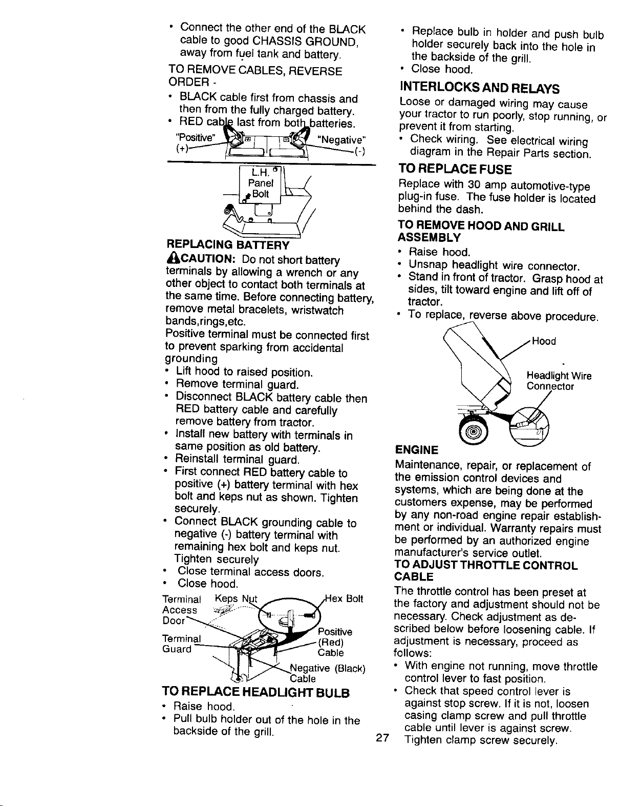
REPLACING BATTERY
_ILCAUTION: Do not short battery
terminals by allowing a wrench or any
other object to contact both terminals at
the same time. Before connecting battery,
remove metal bracelets, wristwatch
bands,rings,etc.
Positive terminal must be connected first
to prevent sparking from accidental
grounding
• Lift hood to raised position.
• Remove terminal guard.
• Disconnect BLACK battery cable then
RED battery cable and carefully
remove battery from tractor.
• Install new battery with terminals in
same position as old battery.
• Reinstall terminal guard.
• First connect RED battery cable to
positive (+) battery terminal with hex
bolt and keps nut as shown. Tighten
securely,
• Connect BLACK grounding cable to
negative (-) battery terminal with
remaining hex bolt and keps nut.
Tighten securely
Close terminal access doors.
Close hood.
Terminal Keps N_,j,.,,-_-,._ex Bolt
Access _::" ........"T'_-.- _ .-_f_
Door _"_ _k. _ Y
"_ _ Positive
Terminal __ (Red)
Guard _ Cable
"_1 _Negative (Black)
4,'_,__h,D," Cable
TO REPLACE HEADUGHT BULB
• Raise hood.
• Pull bulb holder out of the hole in the
backside of the grill.
• Replace bulb in holder and push bulb
holder securely back into the hole in
the backside of the grill.
• Close hood.
INTERLOCKS AND RELAYS
Loose or damaged wiring may cause
your tractor to run poorly, stop running, or
prevent it from starting.
• Check wiring. See electrical wiring
diagram in the Repair Parts section.
TO REPLACE FUSE
Replace with 30 amp automotive-type
plug-in fuse. The fuse holder is located
behind the dash.
TO REMOVE HOOD AND GRILL
ASSEMBLY
• Raise hood.
• Unsnap headlight wire connector.
• Stand in front of tractor. Grasp hood at
sides, tilt toward engine and lift off of
tractor.
• To replace, reverse above procedure.
Headlight Wire
Connector
27
ENGINE
Maintenance, repair, or replacement of
the emission control devices and
systems, which are being done at the
customers expense, may be performed
by any non-road engine repair establish-
ment or individual. Warranty repairs must
be performed by an authorized engine
manufacturer's service outlet.
TO ADJUST THROTTLE CONTROL
CABLE
The throttle control has been preset at
the factory and adjustment should not be
necessary. Check adjustment as de-
scribed below before loosening cable. If
adjustment is necessary, proceed as
follows:
• With engine not running, move throttle
control lever to fast position.
• Check that speed control lever is
against stop screw. If it is not, loosen
casing clamp screw and pull throttle
cable until lever is against screw.
Tighten clamp screw securely.
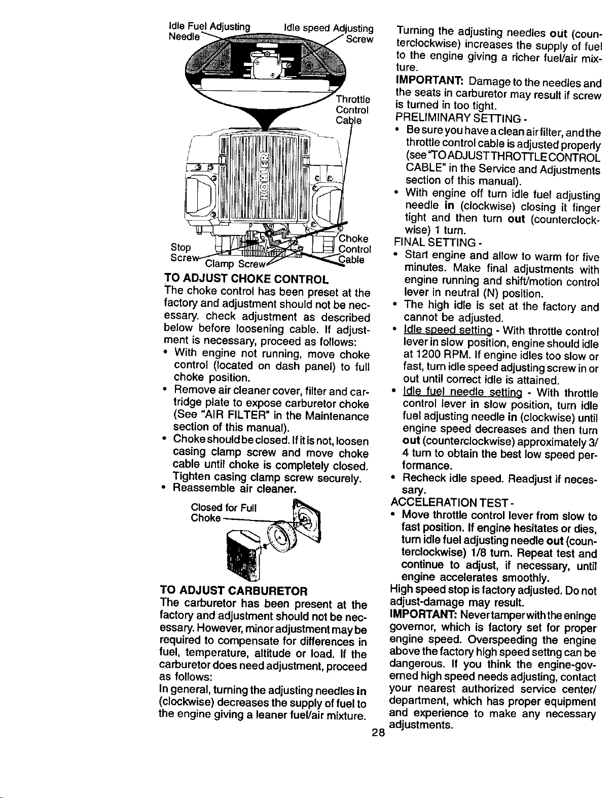
Idle Fuel Adjusting Idle speed Adjusting
Throttle
Control
Stop
Control
Clamp Screv
TO ADJUST CHOKE CONTROL
The choke control has been preset at the
factory and adjustment should not be nec-
essary, check adjustment as described
below before loosening cable. If adjust-
ment is necessary, proceed as follows:
• With engine not running, move choke
control (located on dash panel) to full
choke position.
• Remove air cleaner cover, filter and car-
tridge plate to expose carburetor choke
(See "AIR FILTER" in the Maintenance
section of this manual).
• Choke should be closed. If it is not, loosen
casing clamp screw and move choke
cable until choke is completely closed.
Tighten casing clamp screw securely.
• Reassemble air cleaner.
Closed for Full
Choke
TO ADJUST CARBURETOR
The carburetor has been present at the
factory and adjustment should not be nec-
essary. However, minor adjustment may be
required to compensate for differences in
fuel, temperature, altitude or load. If the
carburetor does need adjustment, proceed
as follows:
In general, turning the adjusting needles in
(clockwise) decreases the supply of fuel to
the engine giving a leaner fuel/air mixture.
Turning the adjusting needles out (coun
terclockwise) increases the supply of fue
to the engine giving a richer fuel/air mix
ture.
IMPORTANT: Damage to the needles an,
the seats in carburetor may result if screv
is turned in too tight.
PRELIMINARY SETTING -
• Be sure you have aclean air filter, and th,
throttle control cable is adjusted properl!
(see "TO ADJUSTTHROTTLE CONTROl
CABLE" in the Service and Adjustment_
section of this manual),
• With engine off turn idle fuel adjustin_j
needle in (clockwise) closing it fingel
tight and then turn out (counterclock-
wise) 1 turn.
FINAL SETTING -
• Start engine and allow to warm for five
minutes. Make final adjustments with
engine running and shift/motion centre
lever in neutral (N) position.
• The high idle is set at the factory ant
cannot be adjusted.
• Idle soeed setting - With throttle centre
lever in slow position, engine should idl_
at 1200 RPM. If engine idles too slow el
fast, turn idle speed adjusting screw in o=
out until correct idle is attained.
• Idle fuel needle settina - With throttle
control lever in slow position, turn idle
fuel adjusting needle in (clockwise) until
engine speed decreases and then turn
out (counterclockwise) approximately 3/
4 turn to obtain the best low speed per-
formance.
• Recheck idle speed. Readjust if neces-
sary.
ACCELERATION TEST -
• Move throttle control lever from slow to
fast position. If engine hesitates or dies,
turn idle fuel adjusting needle out (coun-
terclockwise) 118 tum. Repeat test and
continue to adjust, if necessary, until
engine accelerates smoothly.
High speed stop is factory adjusted. Do not
adjust-damage may result.
IMPORTANT: Never tamper with the eninge
governor, which is factory set for proper
engine speed. Overspeeding the engine
above the factory high speed settng can be
dangerous. If you think the engine-gov-
erned high speed needs adjusting, contact
your nearest authorized service center/
department, which has proper equipment
and experience to make any necessary
adjustments.
28
Immediately prepare your tractor for
storage at the end of the season or if the
tractor will not be used for 30 days or
more.
• ILCAUTION" Never store the tractor
with gasoline in the tank inside a
building where fumes may reach an
open flame or spark. Allow the engine to
cool before storing in any enclosure.
TRACTOR
Remove mower from tractor for winter
storage. When mower is to be stored for
a period of time, clean it thoroughly,
remove all dirt, grease, leaves, etc. Store
in a clean, dry area.
• Clean entire tractor (See "CLEANING"
in the Maintenance section of this
manual).
• Inspect and replace belts, ff necessary
(See belt replacement instructions in
the Service and Adjustments section of
this manual).
• Lubricate as shown in the Mainte-
nance section of this manual.
• Be sure that all nuts, bolts and screws
are securely fastened. Inspect moving
parts for damage, breakage and wear.
Replace if necessary.
• Touch up all rusted or chipped paint
surfaces; sand lightly before painting.
BATTERY
• Fully charge the battery for storage.
• After a period of time in storage,
battery may require recharging.
• To help prevent corrosion and power
leakage during long periods of
storage, battery cables should be
disconnected and battery cleaned
thoroughly (see '3"0 CLE.AN SAT[ERY
AND TERMINALS" in the Maintenance
section of this manual).
• After cleaning, leave cables discon-
nected and place cables where they
cannot come in contact with battery
terminals.
• If battery is removed from tractor for
storage, do not store battery directly on
concrete or damp surfaces.
ENGINE
FUELSYSTEM
IMPORTANT: It is important to prevent
gum deposits from forming in essential warm.
fuel system parts such as carburetor, fuel
filter, fuel hose, or tank during storage. 29
Also, experience indicates that alcohol
blended fuels called gasohol or using
ethanol or methanol) can attract moisture
which leads to separation and formation
of acids during storage. Acidic gas can
damage the fuel system of an engine
while in storage.
• Drain the fuel tank.
• Start the engine and let it run until the
fuel lines and carburetor are empty.
• Never use engine or carburetor
cleaner products in the fuel tank or
permanent damage may occur.
• Use fresh fuel next season.
NOTE: Fuel stabilizer is an acceptable
alternative in minimizing the formation of
fuel gum deposits during storage. Add
stabilizer to gasoline in fuel tank or
storage container. Always follow the mix
ratio found on stabilizer container. Run
engine at least 10 minutes after adding
stabilizer to allow the stabilizer to reach
the carburetor. Do not drain the gas tank
and carburetor if using fuel stabilizer.
ENGINEOIL
Drain oil (with engine warm) and replace
with clean engine oil. (See "ENGINE" in
the Maintenance section of this manual).
CYLINDER(S)
• Remove spark plug(s).
• Pour one ounce of oi! through spark
plug hole(s) into cylinder(s).
• Turn ignition key to "START" position
for a few seconds to distribute oil.
• Replace with new spark plug(s).
OTHER
• Do not store gasoline from one season
to another.
• Replace your gasoline can if your can
starts to rust. Rust and/or dirt in your
gasoline will cause problems.
• If possible, store your tractor indoors
and cover it to give protection from
dust and dirt.
• Cover your tractor with a suitable
protective cover that does not retain
moisture. Do not use plastic. Plastic
cannot breathe which allows conden-
sation to form and will cause your
tractor to rust.
IMPORTANT: Never cover tractor while
engine and exhaust areas are still
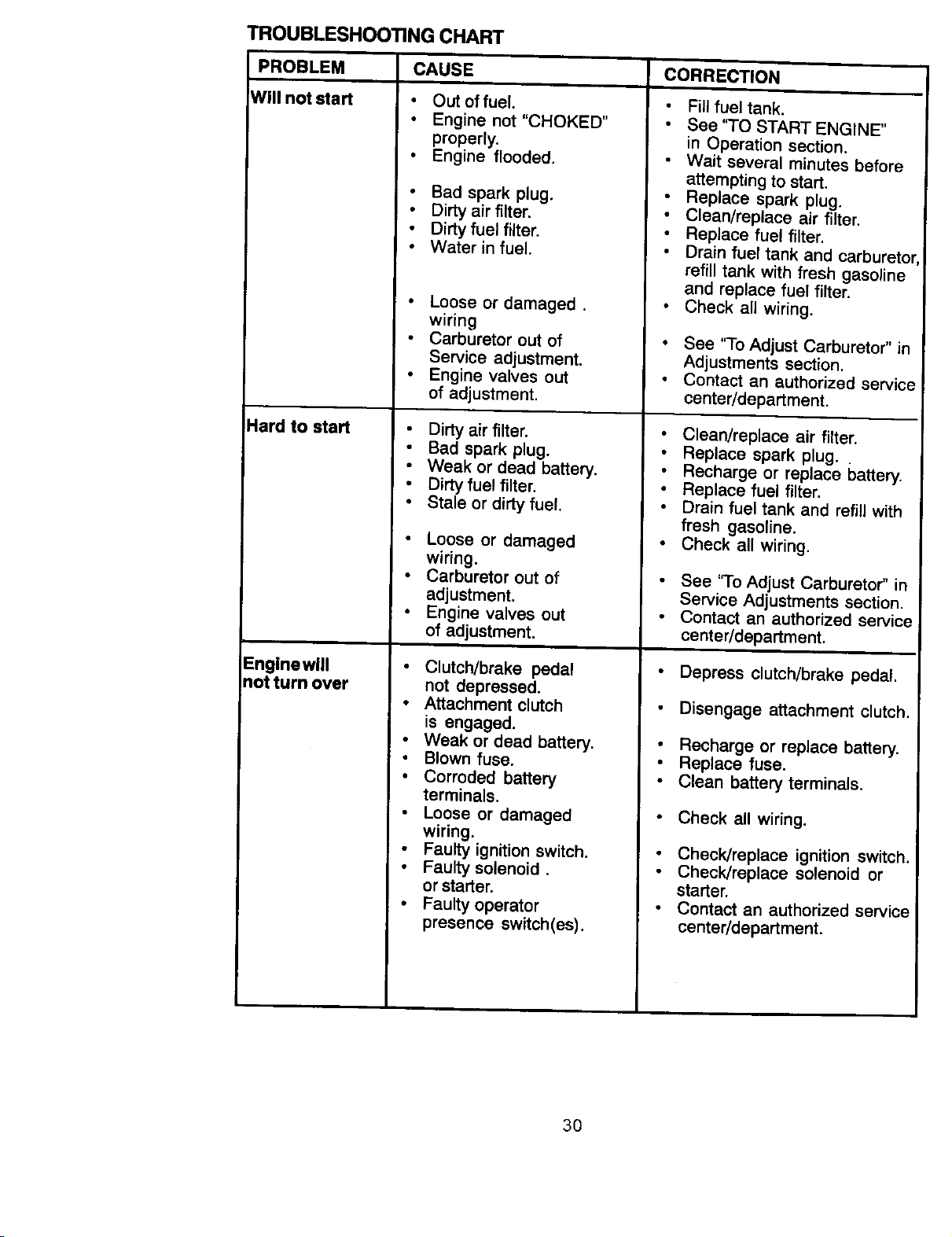
TROUBLESHOOTING CHART
PROBLEM CAUSE
Will not start
IHard to staM
Enginewill
not turn over
i i
CORRECTION
• Out offuel.
Engine not "CHOKED"
properly.
Engine flooded.
• Bad spark plug.
• Dirty air filter.
• Dirty fuel filter.
• Water in fuel.
• Loose or damaged.
wiring
• Carburetor out of
Service adjustment.
• Engine valves out
of adjustment.
• Dirty air filter.
• Bad spark plug.
• Weak or dead battery.
• Dirty fuel filter.
• Stale or dirty fuel.
• Loose or damaged
wiring.
• Carburetor out of
adjustment.
• Engine valves out
of adjustment.
Clutch/brake pedal
not depressed.
• Attachment clutch
is engaged.
Weak or dead battery.
Blown fuse.
• Corroded battery
terminals.
Loose or damaged
wiring.
Faulty ignition switch.
Faulty solenoid.
or starter.
• Faulty operator
presence switch(es),
Fill fuel tank.
See '3-0 START ENGINE"
in Operation section.
Wait several minutes before
attempting to start,
Replace spark plug.
Clean/replace air filter.
Replace fuel filter.
Drain fuel tank and carburetor, I
refill tank with fresh gasoline
and replace fuel filter.
Check all wiring.
See "To Adjust Carburetor" in
Adjustments section.
Contact an authorized service
center/department.
• Clean/replace air filter.
Replace spark plug.
Recharge or replace battery.
Replace fuel filter.
Drain fuel tank and refill with
fresh gasoline.
• Check all wiring.
See "To Adjust Carburetor" in
Service Adjustments section.
Contact an authorized service
center/department.
• Depress clutch/brake pedal.
Disengage attachment clutch.
• Recharge or replace battery.
• Replace fuse.
Clean battery terminals.
• Check all wiring.
• Check/replace ignition switch.
Check/replace solenoid or
starter.
• Contact an authorized service
center/department.
3O
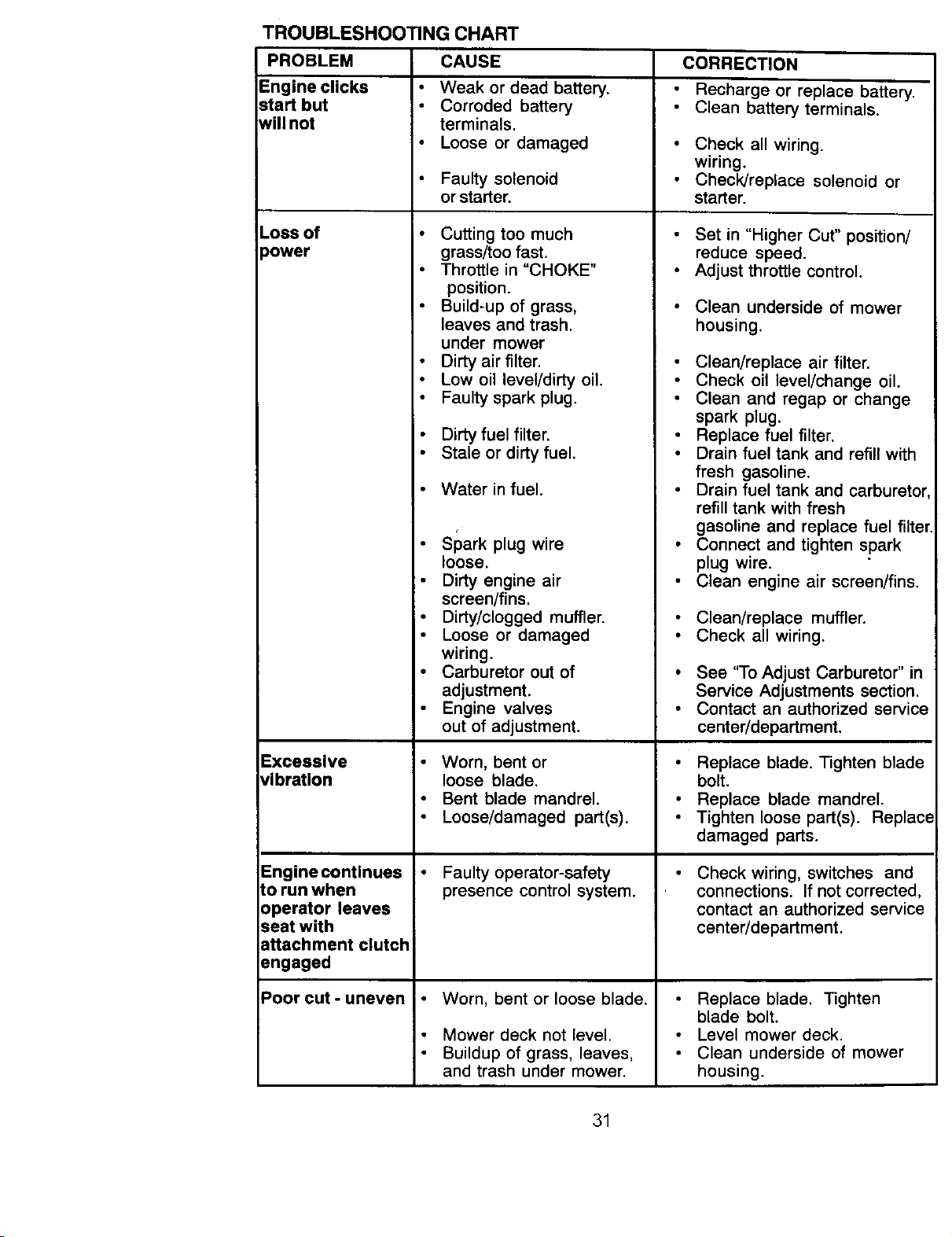
TROUBLESHOOTING CHART
PROBLEM CAUSE
Engine clicks Weak or dead battery.
start but Corroded battery
will not terminals,
• Loose or damaged
Loss of
:)ower
Excessive
_ibration
Engine continues
Lorun when
operator leaves
seat with
attachment clutch
angaged
Poor cut - uneven
Faulty solenoid
or starter.
• Cutting too much
grass/too fast.
Throttle in "CHOKE"
position.
Build-up of grass,
leaves and trash.
under mower
Dirty air filter.
Low oil level/dirty oil.
Faulty spark plug.
Dirty fuel filter.
Stale or dirty fuel.
Water in fuel.
• Spark plug wire
loose.
Dirty engine air
screen/fins.
• Dirty/clogged muffler.
• Loose or damaged
wiring.
• Carburetor out of
adjustment.
Engine valves
out of adjustment.
Worn, bent or
loose blade.
Bent blade mandrel.
Loose/damaged part(s).
Faulty operator-safety
presence control system.
Worn, bent or loose blade.
Mower deck not level.
Buildup of grass, leaves,
and trash under mower.
CORRECTION
Recharge or replace battery.
Clean battery terminals.
Check all wiring.
wiring.
Check/replace solenoid or
starter.
Set in "Higher Cut" position/
reduce speed.
Adjust throttle control.
Clean underside of mower
housing.
Clean/replace air filter.
Check oil level/change oil.
Clean and regap or change
spark plug.
Replace fuel filter.
Drain fuel tank and refill with
fresh gasoline.
Drain fuel tank and carburetor,
refill tank with fresh
gasoline and replace fuel filter.
Connect and tighten spark
plug wire.
Clean engine air screen/fins.
• Clean/replace muffler.
• Check all wiring.
• See "To Adjust Carburetor" in
Service Adjustments section.
• Contact an authorized service
center/department.
• Replace blade. Tighten blade
bolt.
• Replace blade mandrel.
• Tighten loose part(s). Replace
damaged parts.
Check wiring, switches and
connections. If not corrected,
contact an authorized service
center/department.
Replace blade. Tighten
blade bolt.
Level mower deck.
Clean underside of mower
housing.
31
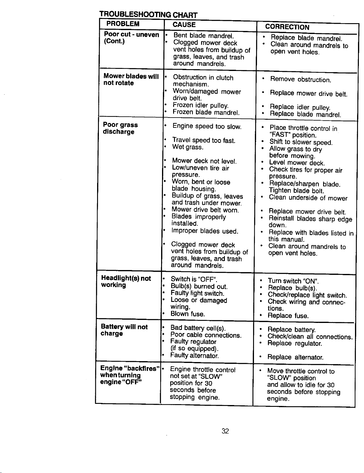
TROUBLESHOOTING CHART
CAUSEPROBLEM
Poor cut - uneven
(Cont.)
Mower blades will
not rotate
Poor grass
discharge
Headlight(s) not
working
Battery will not
charge
Engine "backfires"
when turning
engine "OFF"
Bent blade mandrel.
Clogged mower deck
vent holes from buildup of
grass, leaves, and trash
around mandrels.
Obstruction in clutch
mechanism.
Worn/damaged mower
drive belt.
Frozen idler pulley.
Frozen blade mandrel.
Engine speed too slow.
Travel speed too fast.
• Wet grass.
Mower deck not level.
Low/uneven tire air
pressure.
• Worn. bent or loose
blade housing.
Buildup of grass, leaves
and trash under mower.
Mower drive belt worn,
• Blades improperly
installed.
• Improper blades used.
Clogged mower deck
vent holes from buildup of
grass, leaves, and trash
around mandrels.
Switch is "OFF".
• Bulb(s) burned out.
Faulty light switch.
Loose or damaged
wiring.
Blown fuse,
Bad batterycell(s).
Poor cable connections.
Faulty regulator
(if so equipped).
Faulty alternator.
Engine throttle control
not set at "SLOW"
position for 30
seconds before
stopping engine.
CORRECTION
• Replace blade mandrel.
Clean around mandrels to
open vent holes.
Remove obstruction.
Replace mower drive belt.
• Replace idler pulley.
• Replace blade mandrel.
Place throttle control in
"FAST" position.
Shift to slower speed.
Allow grass to dry
before mowing.
Level mower deck.
Check tires for proper air
pressure.
Replace/sharpen blade.
Tighten blade bolt.
Clean underside of mower
Replace mower drive belt,
• Reinstall blades sharp edge
down.
Replace with blades listed in
this manual.
• Clean around mandrels to
open vent holes.
• Turn switch "ON".
Replace bulb(s).
Check/replace light switch.
Check wiring and connec-
tions.
• Replace fuse,
Replace battery.
Check/clean all connections.
Replace regulator.
• Replace alternator.
• Move throttle control to
"SLOW" position
and allow to idle for 30
seconds before stopping
engine.
32
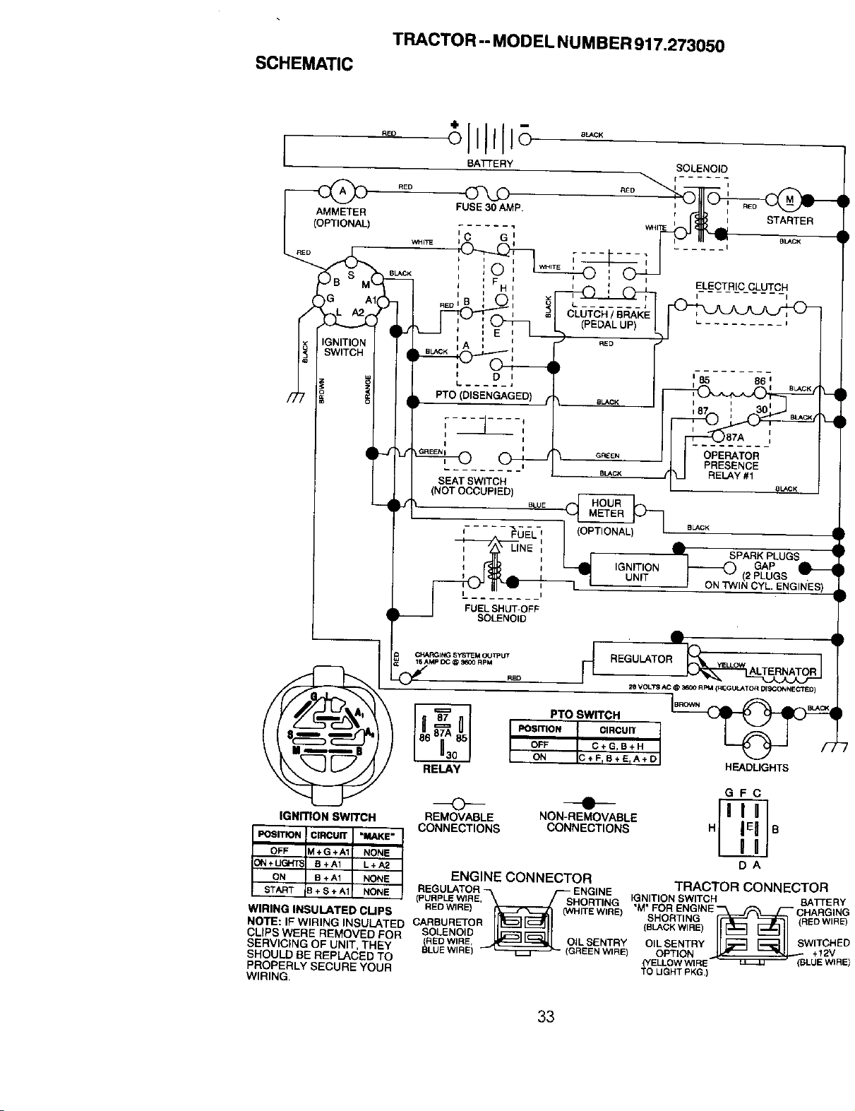
SCHEMATIC
TRACTOR -- MODEL NUMBER 917.273050
BATTERY SOLENOID
,
FUSE30AMP. _lr= f._ _ ; ,Lu -__j-
AMMETER i i STARTER
...... = _ITE I
)
wH,_ I C G i _ BUCK I
: , ,_,
WHITE i i
BLACK F H _l I ELECTRIC CLUTCH
_NITION IA : '
i _ t- aLACK
I i
° I
L ........
CLUTCH/BRAKE
L ......... i
PTO (DISENGAGED)
SEAT SWITCH
(NOT OCCUPIED)
, I_ I _LA°_ !
!
I SPARK PLUGS
GAP
J---'_ (2 PLUGS
_ ON TWIN CYL. ENGINES)
FUEL SHUT-OFF
SOLENOID
_ RPM
RELAY
PTO SWITCH
POSITION CIRCUIT
OFF C+GIB+H
ON C+FrB+ErA+D
• !
2e VOLTS AC @ 3600 RIM {REGULATOR DISCONNECTED)
HEADLIGHTS
GFC
IGNmON SWITCH REMOVABLE NON-REMOVABLE
CONNECTIONS CONNECTIONS H B
ENGINE CONNECTOR TRAC.T(_RCONNECTOR
REGULA OR N NE ...........
(PURPLEWIRE, SHORTING IGNITION SWITCH EATTEF
WIRING INSULATED CLIPS REDWIRE) TE W RE) M FOR ENGINE _ CHARGIf
SHORT'NG (REow,_
NOTE: IFWlRING INSULATED CARBURETOR ll_!_][_ll (E_'OKW'RE)_ _h--ll
CUPBW_REREMOVED_ORSOLENO,O_ _
RED WIRE. OIL SENTRY OIL SENTRY SWITCH
SERVICING OF UNIT, THEY _LUE W RE) REEN WIRE) OPT ON +12V
SHOULD BE REPLACED TO ELLOWWIRE _ (BLUE WJ
PROPERLY SECURE YOUR "_ t3GH'f PKG.)
WIRING.
33
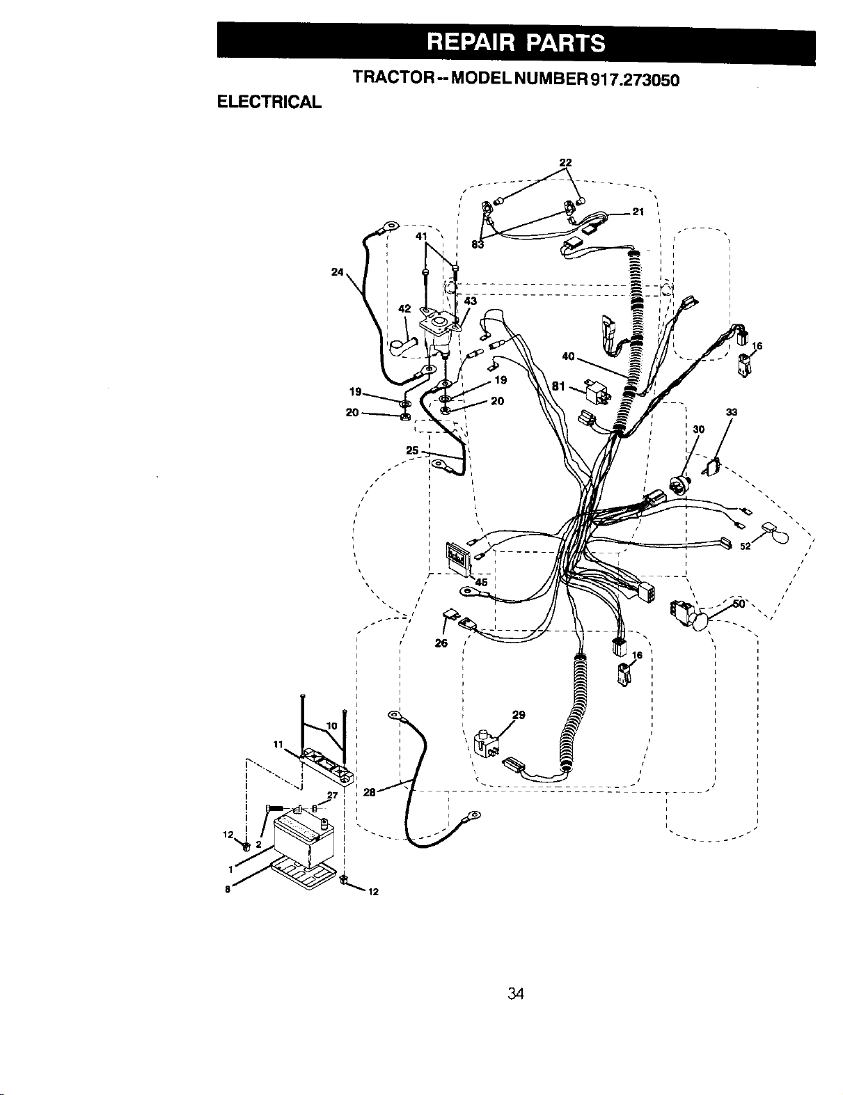
TRACTOR-- MODELNUMBER 917.273050
ELECTRICAL
22
26
29
t
I
J
34
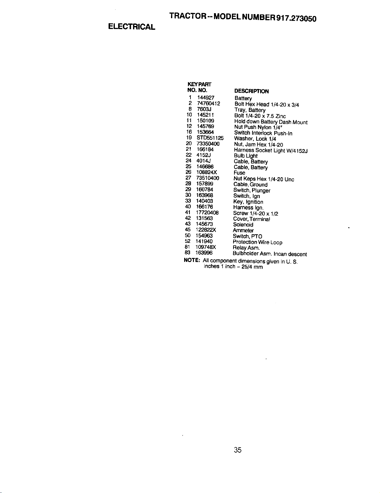
ELECTRICAL
TRACTOR -- MODEL NUMBER 917.273050
KEYPART
NO. NO. DP.SCRIPI1ON
1 144927 Battery
2 74760412 BoltHex Head 1/4-20 x 3/4
8 7603J Tray, Battery
10 145211 Bolt 1/4.20 x 7.5 Zinc
11 150109 Holddown BatteryDash Mount
12 145769 Nut Push Nylon 1/4"
16 153664 Switch Interlock Push-In
19 STD551125 Washer, Lock 1/4
20 73350400 Nut, Jam Hex 1/4-20
21 166184 Harness Socket Ught W/4152J
22 4152J Bulb Ught
24 4014J Cable, Battery
25 146686 Cable, Battery
26 108824X Fuse
27 73510400 Nut Keps Hex 1/4.20 Unc
28 157899 Cabte, Ground
29 160784 Switch, Plunger
30 163968 Switch, Ign
33 140403 Key, Ignition
40 166176 Harness Ign.
41 17720408 Screw 1/4-20 x 1/2
42 131563 Cover,Terminal
43 145673 Solenoid
45 122822X Ammeter
50 154963 Switch, PTO
52 141940 ProtectionWire Loop
81 109748X RetayAsm.
83 163996 BulbholderAsm. Incan descent
NOTE: All component dimensionsgiven in U. S
inches 1 Inch = 25/4 mm
35
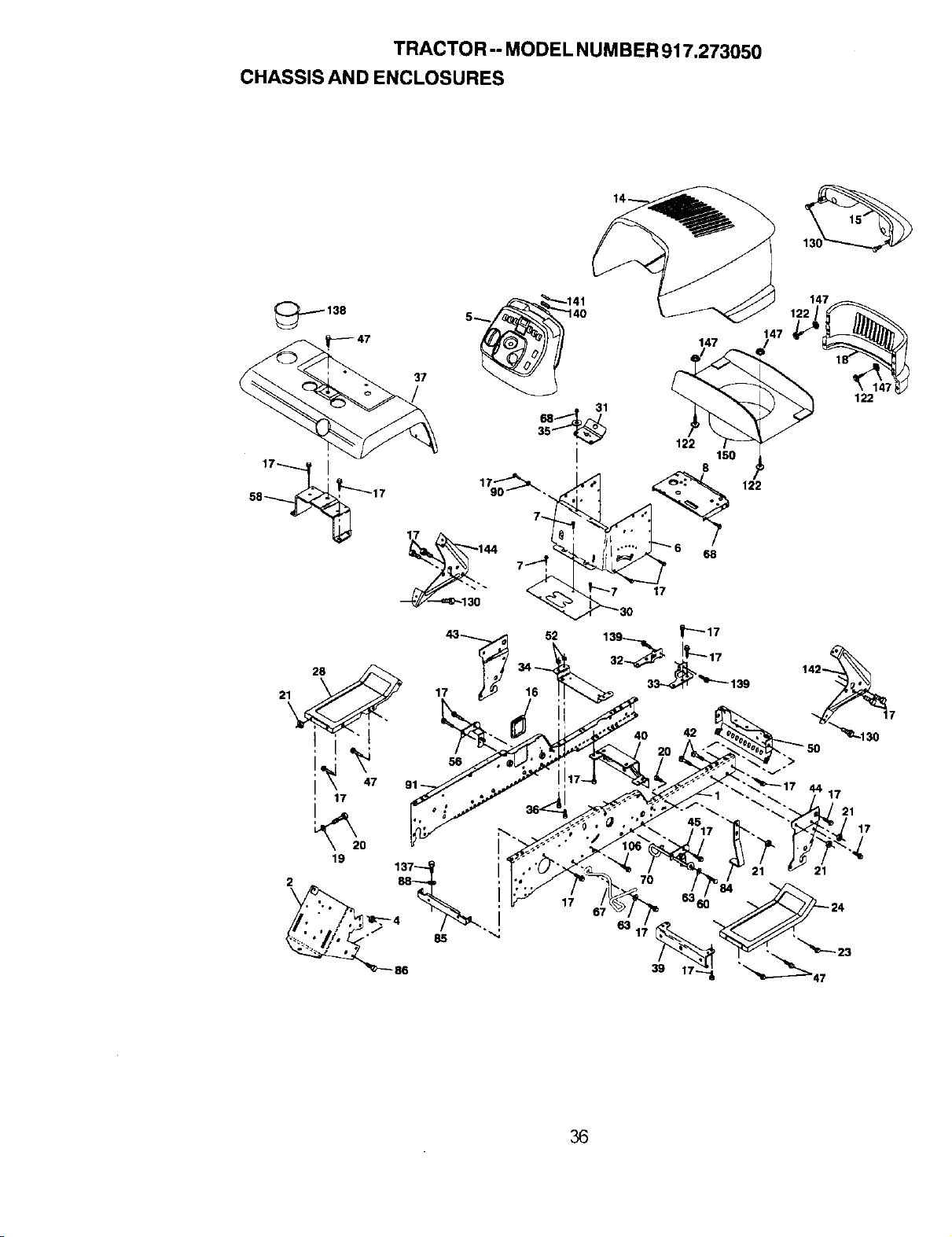
TRACTOR -- MODEL NUM BER 917.273050
CHASSIS AND ENCLOSURES
_138
37
17 144
52
28
21 17
I
17
147
150
8
_ 122
_7 17
_0 42
122
67
63
36
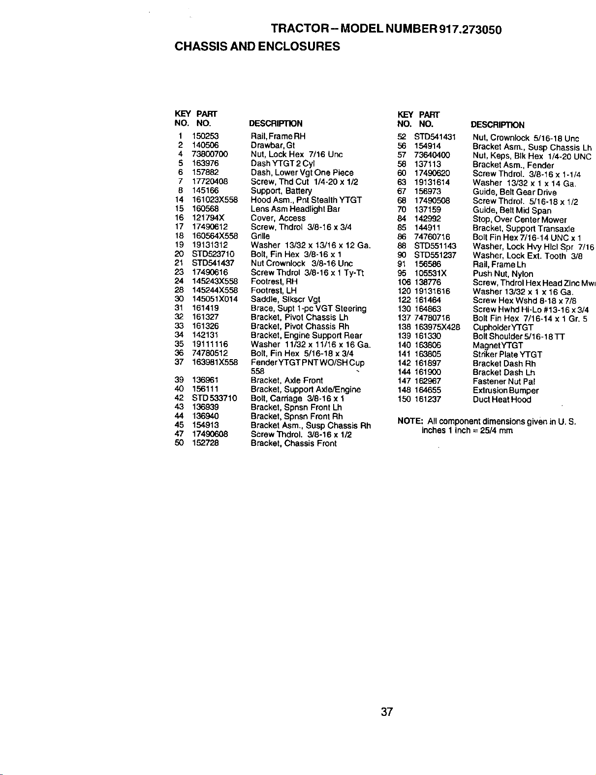
TRACTOR-- MODEL NUMBER 917.273050
CHASSIS AND ENCLOSURES
KEY PART KEY PART
NO. NO. DESCRIPTION NO. NO. DESCRIPTION
1 150253 RaiI, FrameRH 52 STD541431
2 140506 Drawbar, Gt 56 154914
4 73800700 Nut, LockHex 7/16 Uric 57 73640400
5 163976 Dash YTGT 2 Cyl 58 137113
6 157882 Dash, LowerVgtOnePiece 60 17490620
7 17720408 Screw, Thd Cut 1/4-20 x 1/2 63 19131614
8 145166 Support, Battery 67 156973
14 161023X558 Hood Asm., Pnt Stealth YTGT 68 17490508
15 160568 Lens Asm Headlight Bar 70 137159
16 121794X Cover, Access 84 142992
17 17490612 Screw, Thdrol 3/8-16x 3/4 85 144911
18 160564X558 Gdlle 86 74760716
19 19131312 Washer 13/32 x 13/16 x 12 Ca. 88 STD551143
20 STD523710 Bolt, Fin Hex 3/8-16 x 1 90 STD551237
21 STD541437 NutCrownlock 3/8-16Unc 91 156586
23 17490616 ScrewThdrol 3/8-16 x 1Ty-Tt 95 105531X
24 145243X558 Footrest, RH 106 138776
28 145244X558 Footrest, LH 120 19131616
30 145051X014 Saddle, Slkscr Vgt 122 161464
31 161419 Brace, Supt 1*pc VGT Steering 130 164863
32 161327 Bracket, Pivot Chassis Lh 137 74780716
33 161326 Bracket, Pivot Chassis Rh 138 163975X428
34 142131 Bracket, EngineSupport Rear 139 161330
35 19111116 Washer 11132x11116x16Ga, 140 163806
36 74780512 Bott, Fin Hex 5/16-18 x 3/4 141 163805
37 163981X558 FenderYTGTPNTWO/SHCup 142 161897
558 144 161900
39 136961 Bracket, Axle Front 147 162967
40 156111 Bracket, Support Axle/Engine 148 164655
42 STD533710 Bolt, Carhage 3/8-16 x 1 150 161237
43 136939 Bracket, Spnsn Front Lh
44 136940 Bracket, Spnsn Front Rh NOTE: All componentdimensions given in U. S.
45 154913 Bracket Asrn.,Susp Chassis Rh inches 1 inch = 25/4 mm
47 17490608 Screw Thdrol. 3/8-16 x 1/2
50 152728 Bracket, Chassis Front
Nut, Crownlock 5/16-18 Unc
Bracket Asm., Susp Chassis Lh
Nut, Keps, BIk Hex 1/4-20 UNC
Bracket Asm., Fender
Screw ThdroL 3/8-16 x 1-1/4
Washer 13/32 x 1x 14 Ca.
Guide, Belt Gear Drive
Screw ThdroL 5/16-18 x 1/2
Guide, Belt Mid Span
Stop, Over Center Mower
Bracket, Support Transaxle
Bolt Fin Hex 7/16-14 UNC x 1
Washer, Lock Hvy Hlcl Spr 7/16
Washer, Lock Ext. Tooth 3/8
Rail, Frame Lh
Push Nut, Nylon
Screw, Thdrol Hex Head Zinc MwT
Washer 13/32 x 1 x 16 Ga.
Screw Hex Wshd 8-18 x 7/8
Screw Hwhd Hi-Lo #13-16 x 3/4
Bolt Fin Hex 7/16-14 x 1 Gr. 5
Cupholder YTGT
Bolt Shoulder 5/16-18 TT
MagnetYTGT
Stdker Plate YTGT
Bracket Dash Rh
Bracket Dash Lh
Fastener Nut Pal
Extrusion Bumper
Duct Heat Hood
37
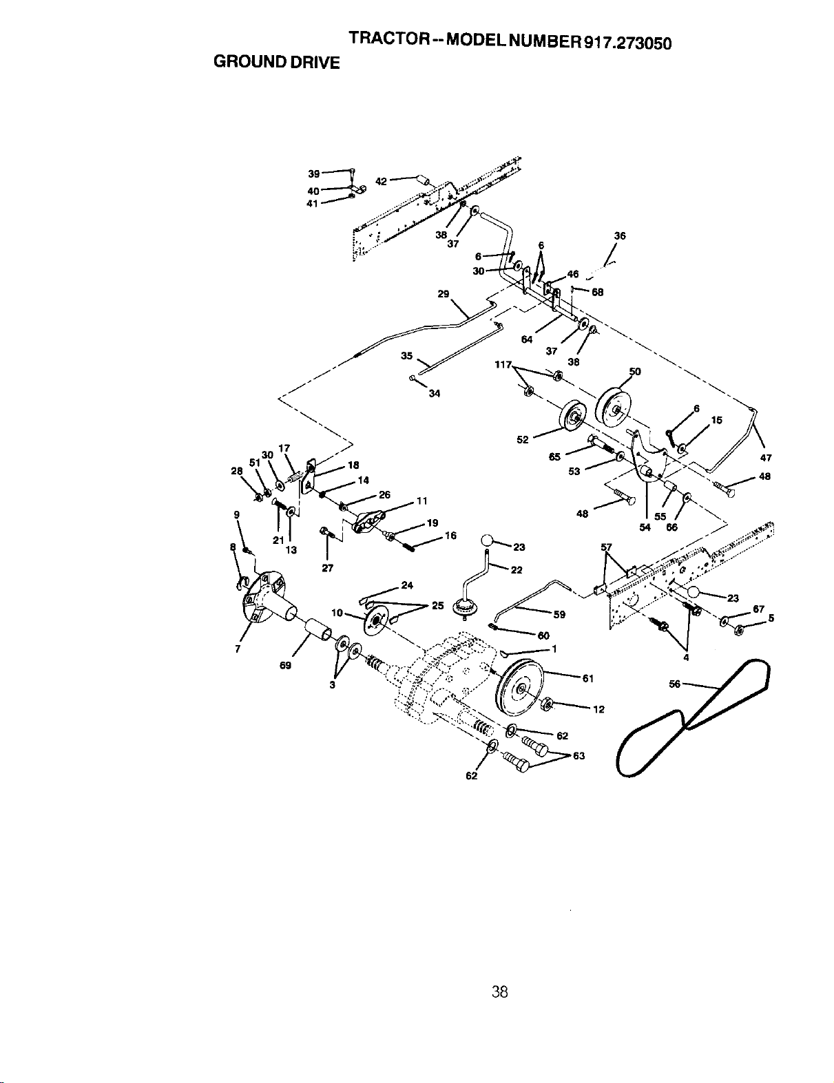
TRACTOR -- MODEL NUMBER 917.273050
GROUND DRIVE
39
28
\
9
27
10_.
69
3
36
i.... 37 6
29
62
38
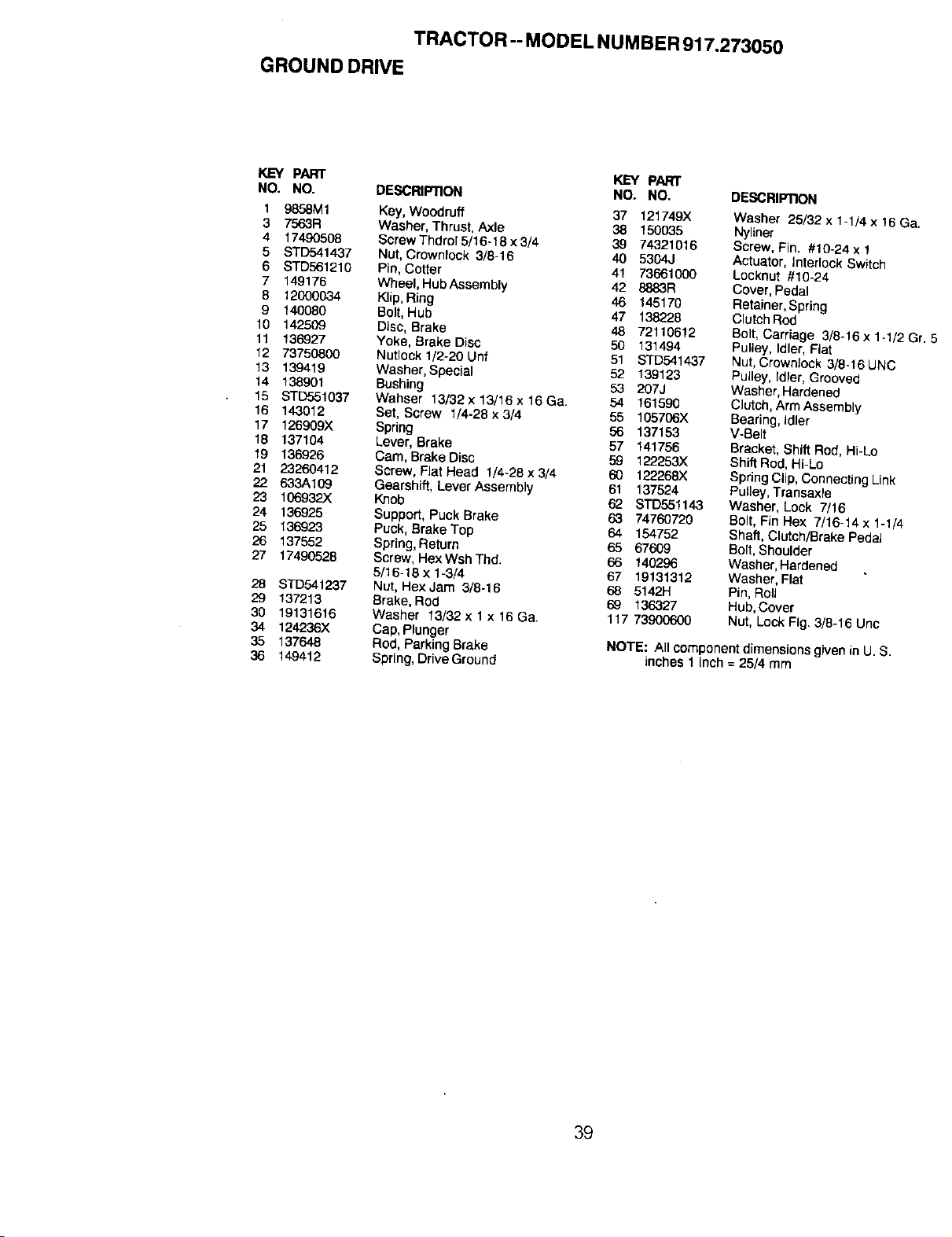
TRACTO R -- MODEL NUMBER 917.273050
GROUND DRIVE
KEY PART KEY PART
NO. NO. DESCRIPTION NO. NO.
1 9858M1 Key, Woodruff 37 121749)(
3 7563R Washer, Thrust, Axle 38 150035
4 17490508 Screw Thdrol 5/16-18 x 3/4 39 74321016
5 STD541437 Not, Crownlock 3/8=16 40 5304J
6 STD561210 Pin,Cotter 41 73661000
7 149176 WheeI, HubAssembly 42 8883R
8 12000034 Klip,Ring 46 145170
9 140080 Bolt, Hub 47 138228
10 142509 Disc, Brake 48 72110612
11 136927 Yoke, Brake Disc 50 131494
12 73750800 Nutlock 1/2-20 Unf 51 STD541437
13 139419 Washer, Special 52 139123
14 138901 Bushing 53 207J
15 STD551037 Wahser 13/32x13/16x16Ga. 54 161590
16 143012 Set, Screw 1/4-28x3/4 55 105706X
17 126909X Spring 56 137153
18 137104 Lever, BraKe 57 141756
19 136926 Cam, Brake Disc 59 122.253X
21 23260412 Screw, Flat Head 1/4-28 x 3/4 60 122,?.68X
22 633A109 Gearshift, Lever Assembty 61 137524
23 106932)( Knob 62 STD551143
24 136925 Support, Puck Brake 63 74760720
25 136923 Puck, Brake Top 64 154752
26 137552 Spring, Return 65 67609
27 17490528 Screw, Hex Wsh Thd. 66 140296
5/16-18x 1-3/4 67 19131312
28 STD541237 Nut, Hex Jam 3/8-16 68 5142H
29 137213 Brake, Rod 69 136327
30 19131616 Washer 13/32 x 1 x 16 Ga. 117 73900600
34 124236X Cap, Plunger
35 137648 Rod, ParkingBrake
36 149412 Spring, Drive Ground
DESCRIPTION
Washer 25/32 x %1/4 x 16 Ga.
Nyllner
Screw, Fin. #10-24 x 1
Actuator, interlock Switch
Locknut #10-24
Cover, Pedal
Retainer, Spring
Clutch Rod
Bolt, Carriage 3/8-16 x 1-1/2 Gr. !
Pulley, Idler, Fiat
Nut, Crownlock 3/8-16 UNC
Pulley, Idler, Grooved
Washer, Hardened
Clutch, Arm Assembly
Bearing, Idler
V-Belt
Bracket, Shift Rod, Hi-Lo
Shift Rod, Hi-Lo
Spring Clip, Connecting Link
Pulley,Transaxte
Washer, Lock 7/16
Bert, Fin Hex 7/16-14 x 1-1/4
Shaft, Clutch/Brake Pedal
Bolt, Shoulder
Washer, Hardened
Washer, Flat
Pin,Roll
Hub, Cover
Nut, Lock Fig. 3/8-16 Unc
NOTE: All componentdimensions given in U. S.
inches 1 inch = 25/4 mm
39
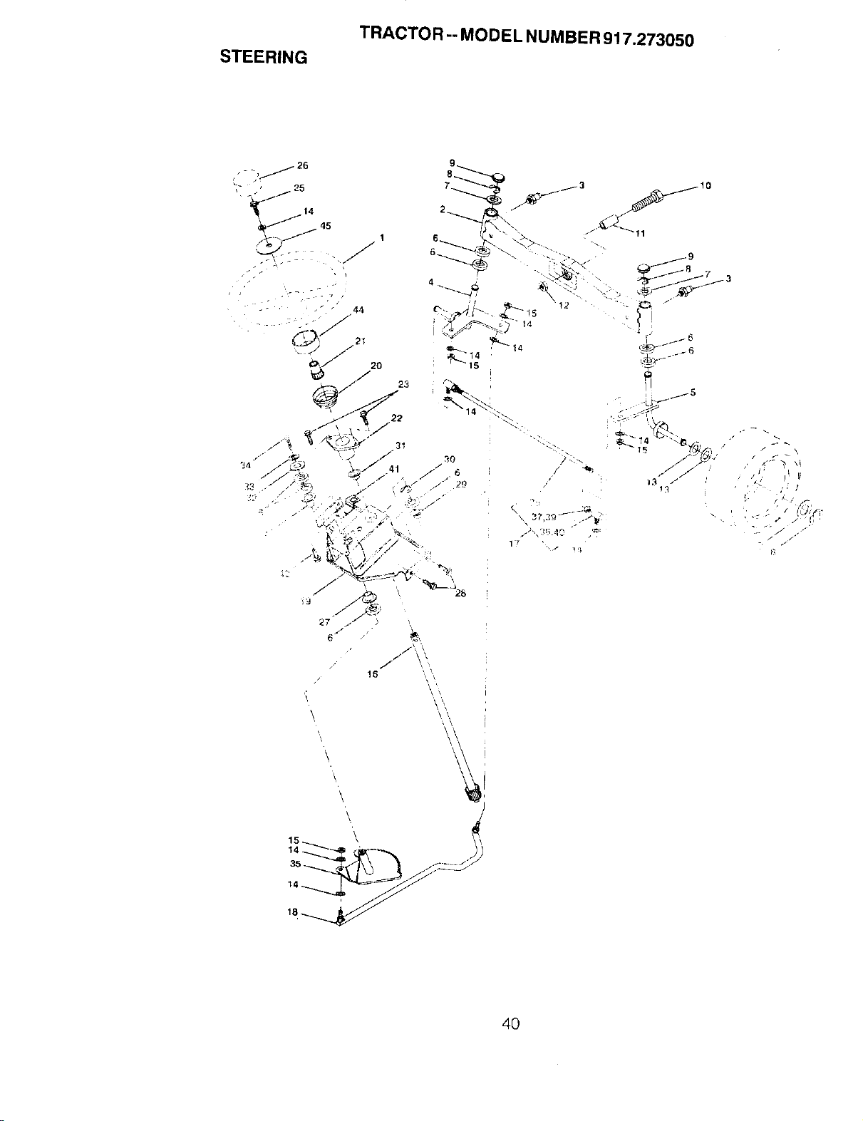
STEERING
TRACTOR -- MODEL NUMBER 917.273050
16
\
40
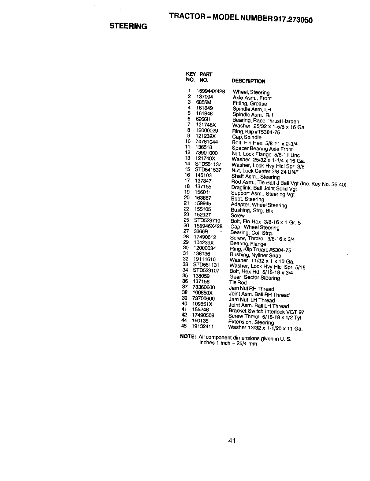
STEERING
TRACTOR -- MODEL NUMBER 917.273050
KEY PART
NO. NO. DESCRIPTION
1 159944X428
2 137094
3 6855M
4 161849
5 161848
6 6266H
7 121748X
8 12000029
9 121232X
10 74781044
11 136518
12 73901000
13 121749)(.
14 STD551137
15 STD541537
16 145103
17 137347
18 137155
19 156011
20 163887
21 159945
22 155105
23 152927
25 STD523710
26 159946X428
27 3366R
28 17490612
29 104239X
30 12000034
31 138136
32 19111610
33 STD551131
34 STD523107
35 138059
36 137156
37 73360600
38 109850X
39 737006o00
40 109851X
41 155246
42 17490508
44 160135
45 19132411
Wheel, Steering
Axle Asm., Front
Fitting,Grease
Spindle Asm, LH
SpindleAsm., RH
Beadng, Race ThrustHarden
Washer 25/32 x 1-5/8 x 16 Ga.
Ring,Klip#T5304-75
Cap, Spindle
Bolt, Fin Hex 5/8-11 x 2-3/4
Spacer BearingAxle Front
Nut, LockFlange 5/8-11 Uric
Washer 25/32 x 1-1/4 x 16 Ga.
Washer, Lock HW HlClSpr 3/8
Nut, LockCenter 3/8-24 UNF
Shaft Asm., Steering
Rod Asm., Tie BallJ BallVgt (inc. Key No. 36-40)
Draglink, Ball Joint Solid Vgt
Support Asm., Steering Vgt
Boot, Steering
Adapter, Wheel Steering
Bushing, Strg. BIk
Screw
Bolt, Fin Hex 3/8-16 x 1 Gr, 5
Cap, Wheel Steering
Bearing, CoL Strg.
Screw, Thrdrol 3/8-16 x 3/4
Bearing,Flange
Ring, KlipTruarc #5304-75
Bushing,NylinerSoap
Washer 11/32 x 1x 10 Ga.
Washer, Lock Hvy Hlcl Spr 5/16
Bolt, Hex Hd 5/16-18 x 3/4
Gear, Sector Steering
Tie Rod
Jam Nut RHThread
Joint Asm. Ball RH Thread
Jam Nut LH Thread
Joint Asm. Ball LH Thread
Bracket Switch Interlock VGT 97
ScrewThdrol 5/16-18 x 1/2 Tyt
Extension, Steering
W_,sher 13132x 1-1/20 x 11 Ga,
NOTE: All component dimensions given in U. S.
inches 1 inch = 25/4 mm
41
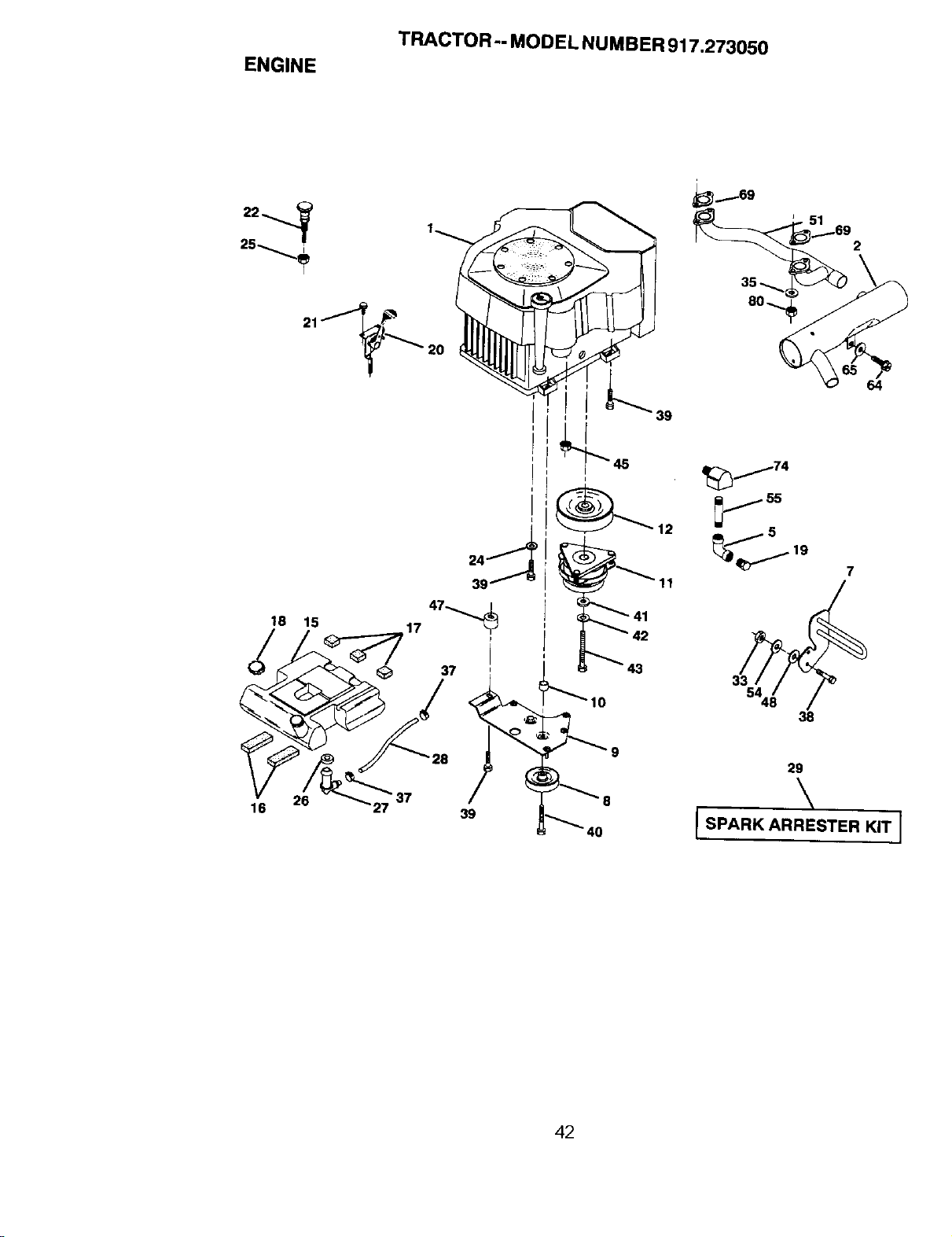
ENGINE
TRACTOR-- MODEL NUMBER 917.273050
_12 r
_3
10
_169
64
_j74
_ ss
_s
_ d_"'_'_ 19 7
54
38
29
\
I SPARK ARRESTER KIT ]
42
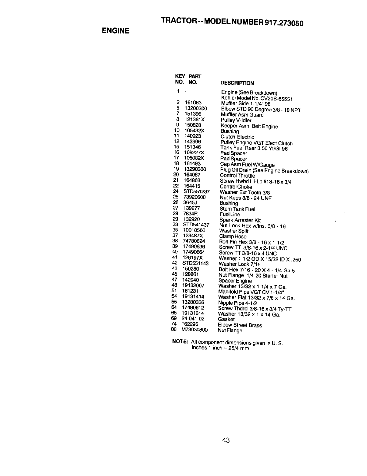
ENGINE
TRACTOR-- MODEL NUMBER 917.273050
KEY PART
NO. NO. DESCRIPTION
1 Engine (See Breakdown)
Kohler Model No.CV20S-65551
2 161063 Muffler Side 1-1/4"98
5 13200300 ElbowSTD 90 Degree 3/8- 18 NPT
7 151396 Muffler Asm Guard
8 121361X Pulley V-Idler
9 t50828 Keeper Asm. Belt Engine
10 1054,32X Bushing
11 140923 Clutch Etectric
12 143996 Pulley Engine VGT Elect Clutch
15 151346 Tank Fuel Rear 3.50 YUGt 96
16 109227)( Pad Spacer
17 106082X Pad Spacer
18 161493 Cap Asm FuelW/Gauge
19 13290300 Plug Oil Drain (See Engine Breakdown)
20 164067 GootrolThroffle
21 164863 Screw Hwhd Hi-Lo #13-16 x 3/4
22 164415 ControlChoke
24 STD551237 Washer Ext Tooth 9/8
25 73920600 Nut Keps 3/8 -24 UNF
26 3645J Bushing
27 139277 StemTank Fuel
28 7834R FuelLine
29 132920 Spark Arrester Kit
33 STD541437 Nut Lock Hex w/Ins. 3/8 - 16
35 10010500 Washer Split
37 123487)( ClampHose
38 74780624 BoltFin Hex 3/8 - 16x 1-1/2
39 17490636 ScrewTr 3/8-16x2-1/4UNC
40 17490664 Screw'i-r 3/8-t6 x 4 UNC
41 126197X Washer 1ol/20D X 15/32 ID X .250
42 STD551143 Washer Lock 7/16
43 150280 Bo)tHex 7/16 - 20 X 4 - 1/4 Ga 5
45 128861 Nut Flange 1/4-20 Starter Nut
47 142040 Spacer Engine
48 19132007 Washer 13/32 x 1-1/4 x 7 Ga.
51 161231 Manifold Pipe VGT CV 1-1/4"
54 19131414 Washer Flat 13/32 x 7f8 x 14 Ga,
55 13280336 Nipple Pipe 4-1/2
64 17490612 ScrewThdrot 3/8-t 6 x 3/4 Ty-TL"
65 19131614 Washer 13/32 x 1 x 14 Ga.
69 24-041-02 Gasket
74 162295 Elbow Street Brass
80 M73030800 NutFlaege
NOTE: All component dimensionsgiven in U. S.
inches 1 inch = 25/4 mm
43
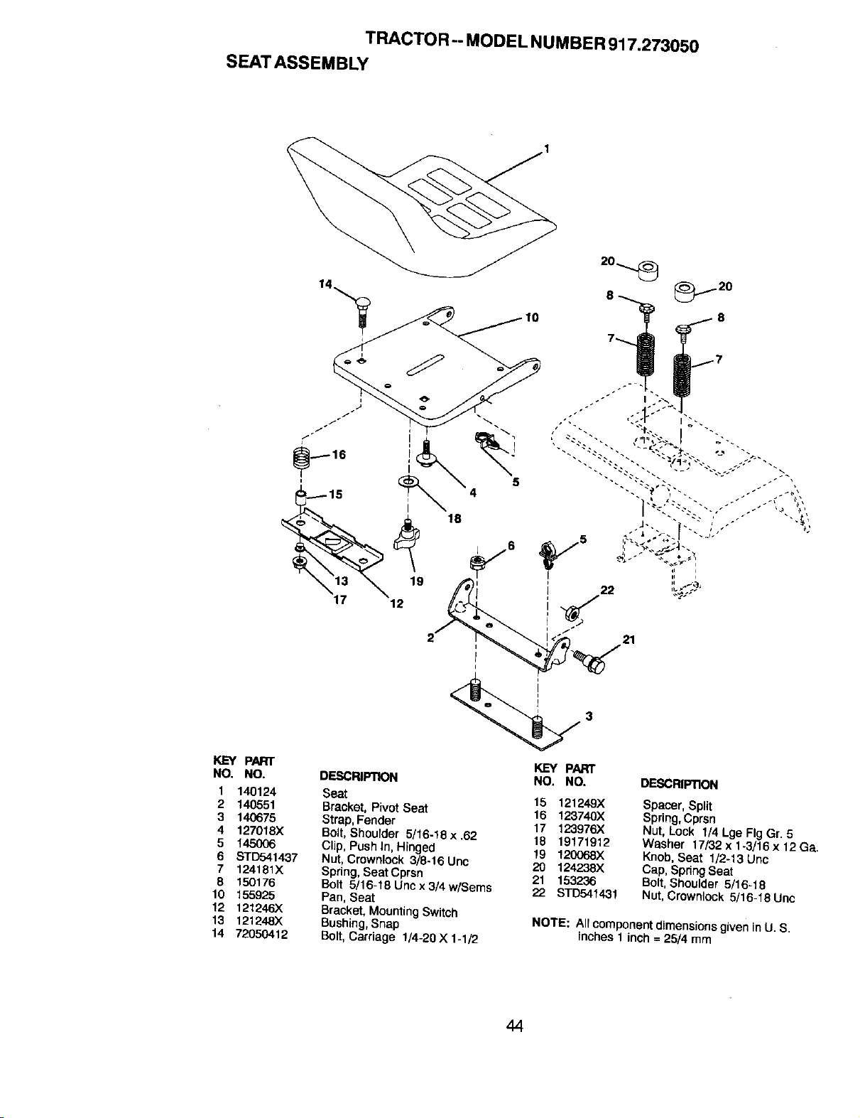
TRACTOR-- MODEL NUMBER 917.273050
SEATASSEMBLY
19
12
21
KEY PART
NO. NO.
1 140124
2 140551
3 140675
4 127018X
5 145006
6 STD541437
7 124181X
6 150176
10 155925
12 121246X
13 121248X
14 72050412
3
DESCRIPTION
Seat
Bracket, Pivot Seat
Strap, Fender
Bolt, Shourder 5/16.18x.62
Clip, Push In, Hinged
Nut, Crownlock 3/8-16 Unc
Spring, Seat Cprsn
Bolt 5/16-18 Unc x 3/4 w/Sems
Pan, Seat
Bracket, MountingSwitch
Bushing, Snap
Bolt,Carriage 1/4-20X 1-1/2
KEY PART
NO. NO.
15 121249X
16 123740X
17 123976X
18 19171912
19 120068X
20 124238X
21 153236
22 STD54.1431
DEBCRIP'nON
Spacer, Split
Spdng,Cprsn
Nut, Lock 1/4 Lge Fig G[. 5
Washer 17/32 x 1-3/16 x 12 Ga.
Knob, Seat 1/2-13 Unc
Cap, Spdng Seat
Bolt, Shoulder 5/16-18
Nut, Crown_ock 5/16-18 Uric
NOTE: All component dimensions given inU. S.
inches 1 inch =25/4 mm
44
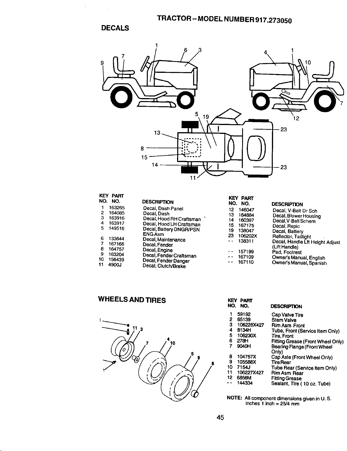
DECALS
TRACTOR- MODEL NUMBER 917.273050
7
3
1
10
5
12
8
15
14
11
KEY PART
NO. NO.
1 163265
2 164O85
3 163916
4 163917
5 149516
6 133644
7 167166
6 164757
9 163204
10 156439
11 4900J
DESCRIPTION
Decal, Dash Panel
Decat,Dash
Decal,Hood RH Craftsman "
Decal,Hood LH Craftsman
Decal,BatteryDNGR/PSN
ENGAsro
Decal,Maintenance
Decal,Fender
Decal, Engine
Decal,FenderCraftsroan
Decal,FenderDanger
Decal,Clutch/Brake
KEY PART
NO. NO.
12 146047
13 164884
14 160397
15 167175
19 138047
23 106202X
- - 138311
-- 157199
-- 167109
-- 167110
DESCRIPTION
Decal, V-Belt Dr Sch
Decal, BlowerHousing
Decal,V-Belt Schero
Decal, Replc
Decal, Battery
Reflector,Taillight
Decal, Handle Lft HeightAdjust
(Lift Handle)
Pad, Footrest
Owner's Manual, English
Owner's Manual,Spanish
WHEELS AND TIRES
t-....___...,
3
7
4
10
g
KEY PARr
NO. NO.
1 59192
2 65139
3 106228X427
4 81341"t
5 106230X
6 278H
7 9040t-I
8 104757X
8 9 105588X
10 7154J
11 106227X427
12 6856M
-- 144334
DESCRIPTION
Cap ValveTire
Stem Valve
RimAsro Front
Tube, Front (Service Item Only)
Tire, Front
FittingGrease (Front Wheel Onl'
BearingFlange(FrontWheel
Only)
Cap Axle (FrontWheel Only)
Tire Rear
Tube Real (Service Item Only)
Rim Asm Rear
FittingGrease
Sealant, Tire ( 10 oz. Tube)
NOTE: All componentdimensionsgiven in U. S.
inches 1 inch = 25/4 mro
45
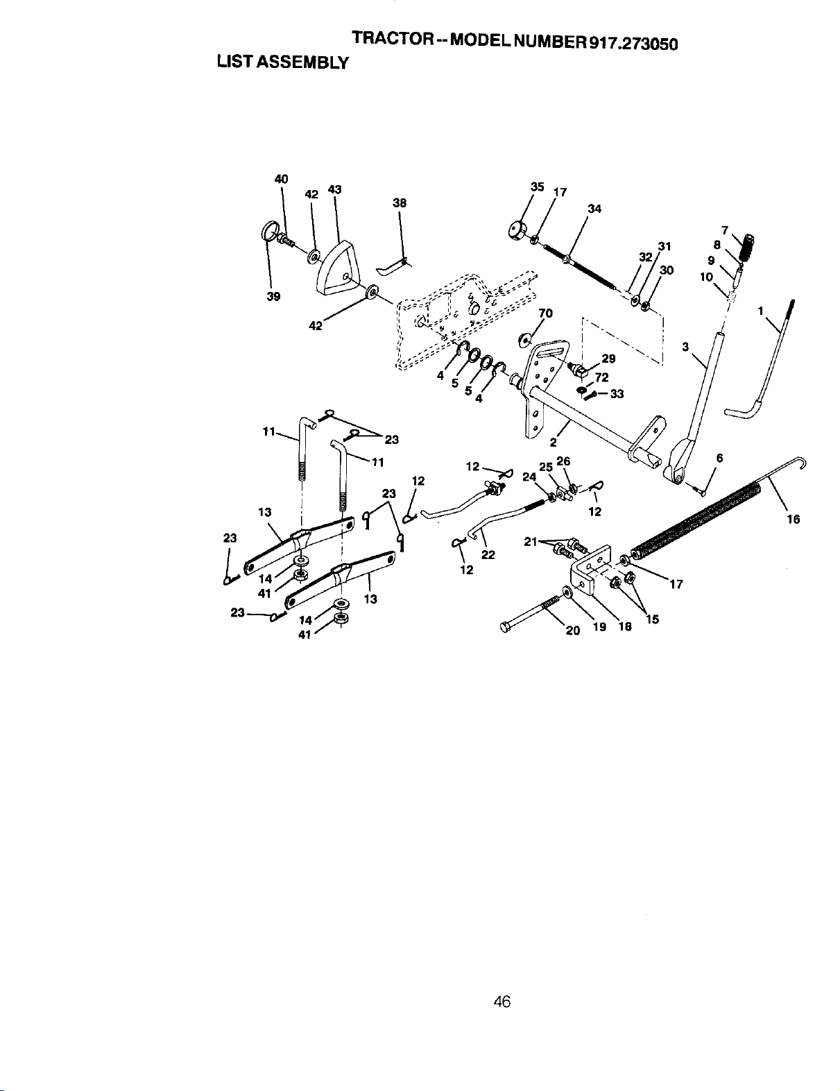
TRACTOR -- MODEL NUMBER 917.273050
LIST ASSEMBLY
40
39
42
35 17
70
34
12 _ 24 \ \
13 I 23 . 1_2
_2__ 20 19 18
12
16
46
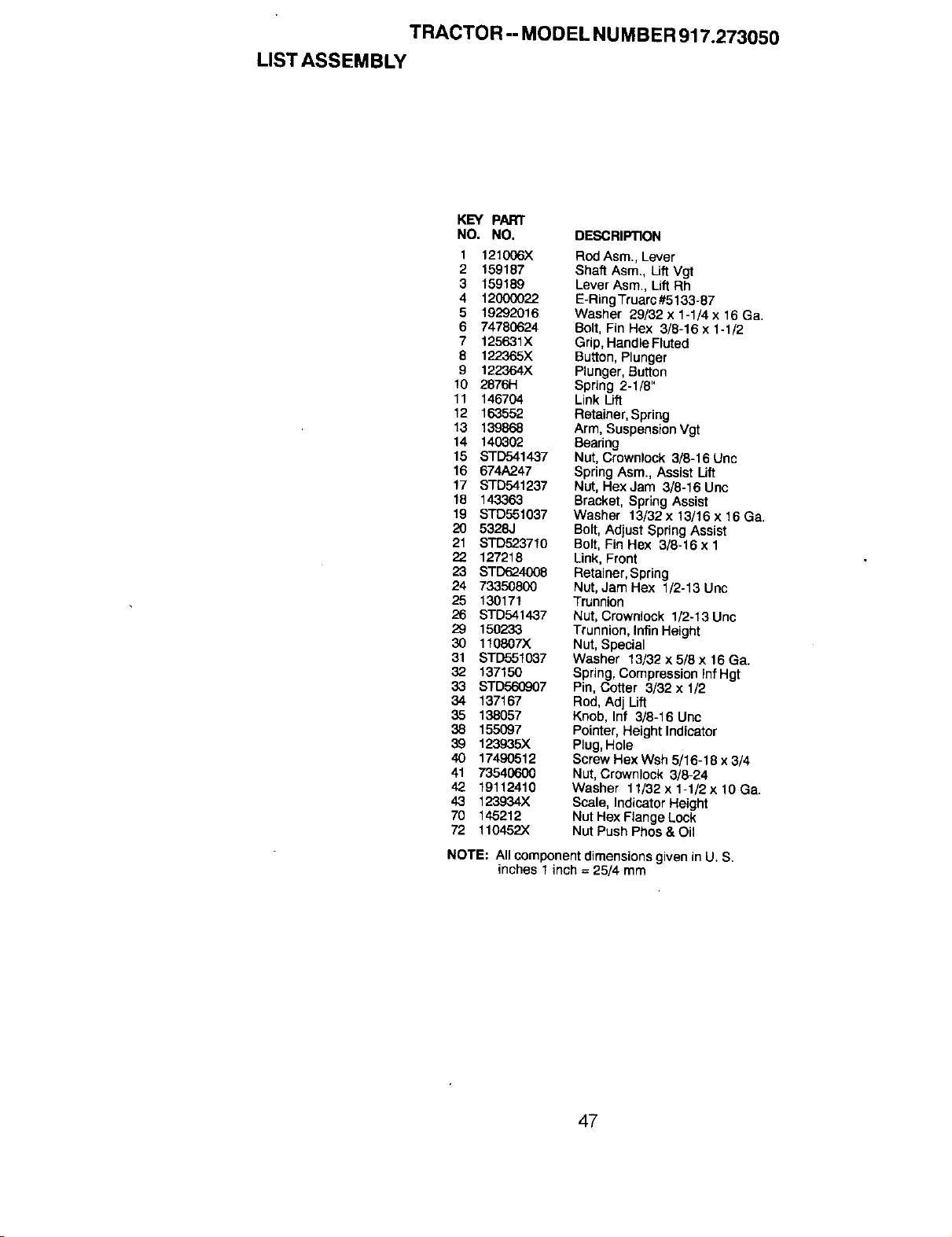
TRACTOR-- MODEL NUMBER 917.273050
LIST ASSEMBLY
KEY PART
NO. NO. DESCRIPTION
1 121006X RodAsm., Lever
2 159187 Shaft Asm., Lift Vgt
3 159189 Lever Asm., Lift Rh
4 12000022 E-RingTruarc#5133-87
5 19292016 Washer 29/32 x 1-1/4 x 16 Ga.
6 74780624 Bolt, Fin Hex 3/8-16 x 1-1/2
7 125631X Grip, HandleFluted
8 122365X Button, Plunger
9 122364X Plunger, Button
10 2876H Spring 2-1/8"
11 146704 Link Lift
12 163552 Retainer, Spring
13 139868 Arm, SuspensionVgt
14 140302 Bearing
15 STD541437 Nut, Crownlock 3/8-16 Unc
16 674A247 Spring Asm., Assist Uft
17 S_1237 Nut, Hex Jam 3/8-16 Unc
18 143363 Bracket, Spring Assist
19 STD551037 Washer 13/32x13/16x16Ga.
20 5328J Bolt, Adjust Spring Assist
21 STD523710 Bolt, Fin Hex 3/8-16 x 1
127218 Link, Front
23 STD624008 Retainer, Spring
24 73350800 Nut,JamHex 1/2-13Unc
25 130171 Trunnion
26 STD541437 Nut, Crownlock 1/2-13 Unc
29 150233 Trunnion, lnfin Height
30 110807X Nut, Special
31 STD551037 Washer 13/32 x 5/8 x 16 Ga.
32 137150 Spring, Compression InfHgt
33 STD560907 Pin, Cotter 3/32 x 1/2
34 137167 Rod, Adj Lift
35 138057 Knob, Inf 3/8-16 Unc
38 155097 Pointer, Height Indicator
39 123935X Plug,Hole
40 17490512 Screw Hex Wsh 5/16-18 x 3/4
41 73540600 Nut, Crownlock 3/8-24
42 19112410 Washer 11/32x1-1/2x10Ga.
43 123934X Scale, Indicator Height
70 145212 Nut Hex Flange Lock
72 110452X Nut Push Phos & Oil
NOTE: All componentdimensions given in U. S.
inches 1 inch = 25/4 mm
47
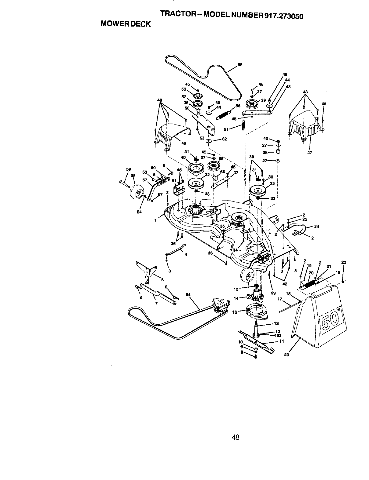
TRACTOR -. MODEL NUMBER 917.273050
MOWER DECK
45
53,
49
36
4 36
55
45
43
48
47
48
22
54
_" 1123
48
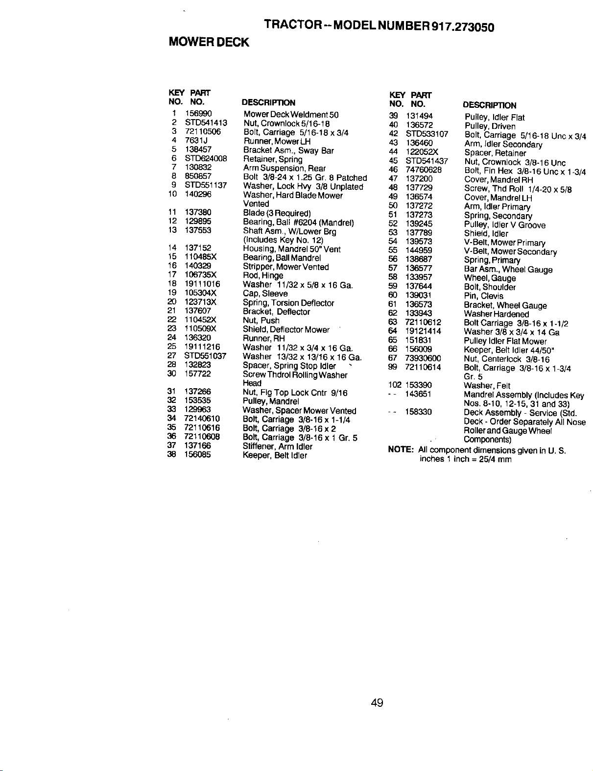
TRACTOR --MODEL NUMBER 917.273050
MOWER DECK
KEY pART KEY PARr
NO. NO. DESCRIPTION NO. NO.
1 156990 MowerDeckWetdment50 39 131494
2 STD541413 Nut,Ctownlock 5/16-16 40 136572
3 72110506 Bolt, Carriage 5/16-18x3/4 42 STD5.33107
4 7631J Runner, MowerLH 43 136460
5 138457 Bracket Asm., Sway Bar 44 122.052.X
6 STD624008 Retainer,Spring 45 STD541437
7 130832 Arm Suspension, Rear 46 74760628
8 850857 Bolt 3/8-24 x 1.25 Gr. 8 Patched 47 137200
9 BTD551137 Washer, Lock HW 3/8 Unplated 48 137729
10 140296 Washer, Hard Blade Mower 49 136574
Vented 50 137272
11 137380 Blade (3 Required) 51 137273
12 129895 Bearing, Bal_ #6204 (Mandrel) 52 139245
13 137553 Shaft Asm.,W/Lower Brg 53 137789
(Includes Key No. 12) 54 139573
14 137152 Housing, Mandrel50"Vent 55 144959
15 110485X Beering,BalIMandre_ 56 138687
16 140329 Stripper, MowerVented 57 136577
17 106735X Rod, Hinge 58 133957
18 19111016 Washer 11/32x5/8x16Ga. 59 137644
19 105304X Cap, Sleeve 60 139031
20 123713X Spring, Torsion Deflector 61 136573
21 137607 Bracket, Deflector 62 133943
22 110452X Nut, Push 63 72110612
23 110509X Sh{eld,Def_ectorMewer 64 19121414
24 136320 Runner,RH 65 151831
25 19111216 Washer 11/32x3/4x16Ga. 66 156009
27 STD551037 Washer 13/32 x 13/t6 x 16 Ge. 67 73930600
29 132823 Spacer, Spring Step Idler 99 72110614
30 157722 ScrewThdrolRolUngWasher
Head 102 153390
31 137266 Nut, FIgTop Lock Cntr 9/16 -- 143651
32 153535 Pulley,Mandrel
33 129963 Washer, Spacer Mower Vented - - 158330
34 72140610 Bolt, Carriage 3/6-16 x1-1/4
35 72110616 Bolt, Carriage 3/8-16x2
36 72110609 Bolt, Carriage 3/6-t6xl Gr. 5
37 137166 Stiffener, Arm Idler
38 156085 Keeper, Beltldler
DESCRIP13ON
Pulley, Idler F_at
Pulley, Driven
Bo_t,Carriage 5116-18 Unc x 3,
Arm, Idler Secondary
Spacer, Retainer
Nut, Crownlock 3/8-16 Unc
Bolt, Fin Hex 318-16 Uricx 1-3_
Cover, Mandrel RH
Screw, Thd Rell 1/4-20 x 5/8
Cover, Mandrel LH
Arm, Idler Primary
Spring, Secondary
Pulley, _dlerV Groove
Shield, Idler
V-BeLt,Mower Primary
V-Belt, Mower Secondary
Spring,Primary
Bar Asm.,Wheel Gauge
Wheel, Gauge
Bolt, Shoulder
Pin, Clevis
Bracket, WheelGauge
Washer Hardened
BoltCarriage 3/8-16 x 1-1/2
Washer 3/8 x 3/4 x 14 Ga
PulleyIdler FlatMower
Keeper, Belt Idler 44/50"
Nut, Centerlock 3/8-16
Bolt,Carriage 3/8-16 x 1-3/4
Gr. 5
Washer, Felt
MandrelAssembly (Includes K_
Nos. 8-10, 12-15, 31 and 33)
Deck Assembly - Service (Std.
Deck - Order Separately All No=
Rollerand GaugeWheel
Components)
NOTE: All component dimensions given in U. S.
inches 1 inch = 25/4 mm
49
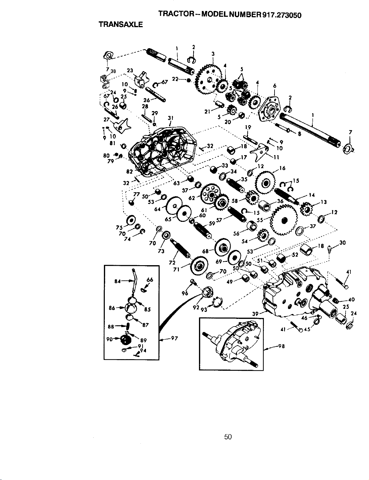
TRANSAXLE
TRACTOR-- MODEL NUMBER 917.273050
7
74
70
73
72
41
25
24
5O
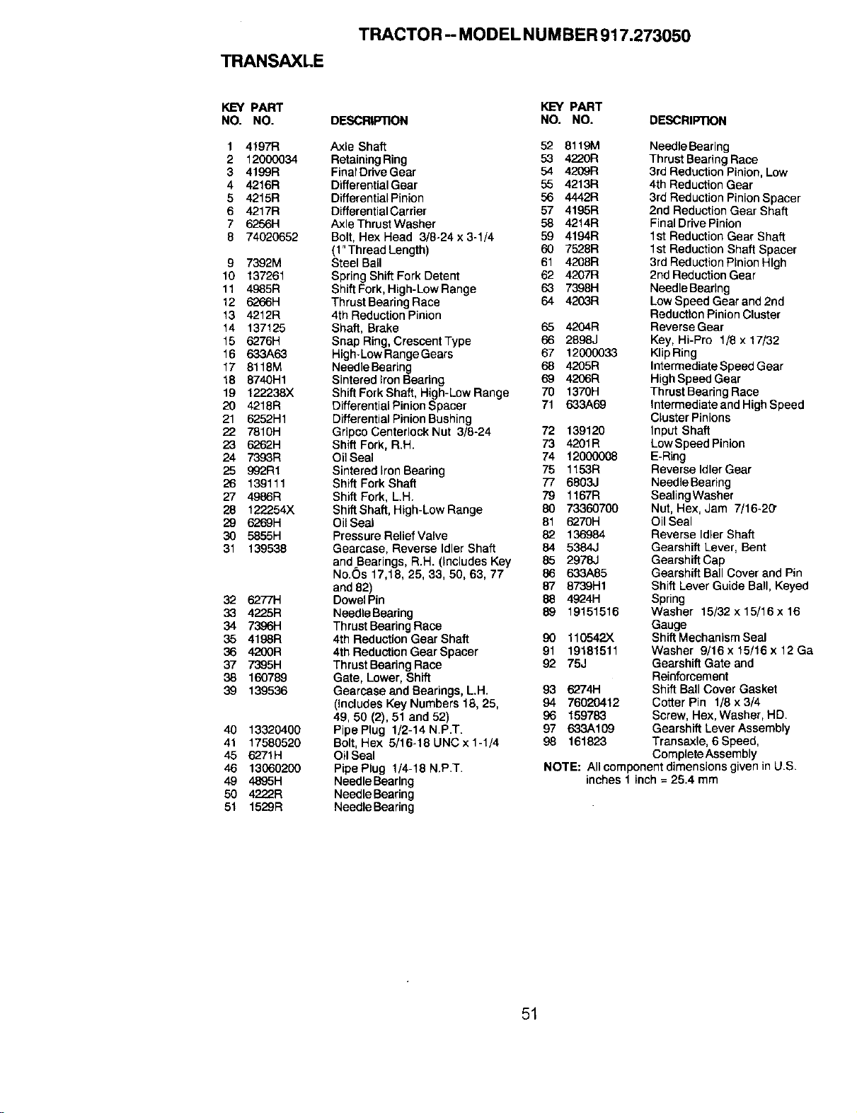
TRANSAXLE
TRACTOR -- MODEL NUMBER 917.273050
KEY PART KEY PART
NO. NO. DESCRIPTION NO. NO. DESCRIPTION
1 4197R
2 12000034
3 4199R
4 4216R
5 4215R
6 4217R
7 6256H
8 74020652
9 7392M
10 137261
11 4985R
12 6266H
13 4212R
14 137125
15 6276H
16 633A63
17 8118M
18 8740H1
19 122238X
20 4218R
21 6252H1
22 7810H
23 6262H
24 7393R
25 992R1
26 139111
27 4986R
28 122254X
29 6269H
30 5855H
31 139538
32 6277H
33 42"25R
34 7396H
35 4198R
36 4200R
37 7395H
38 160789
39 139536
40 13320400
41 17580520
45 6271H
46 13060200
49 4895H
50 4222R
51 1529R
Axle Shaft 52 8119M
Retaining Ring 53 4220R
FinalDrive Gear 54 4209R
Differential Geer 55 4213R
Differential Pinion 56 4442R
Differential Carrier 57 4195R
Axle Thrust Washer 58 4214R
Bolt, Hex Head 3/8-24 x 3-1/4 59 4194R
(l"ThreadLength) 60 7528R
Steel Ball 61 4208R
Spring Shift Fork Detent 62 4207R
Shift Fork, High-LowRange 63 7398H
Thrust Bearing Race 64 4203R
4th Reduction Pinion
Shaft, Brake 65 4204R
Snap Ring, Crescent Type 66 2898J
High-Low Range Gears 67 12000033
Needle Bearing 68 4205R
Sinteredlron Bearing 69 4206R
Shift Fork Shaft, High-Low Range 70 1370H
Differential Pinion Spacer 71 633A69
Differential Pinion Bushing
Gripco Centerlock Nut 3/8-24 72 139120
Shift Fork, R.H. 73 4201R
Oil Seal 74 12000008
Sintered Iron Bearing 75 1153R
Shift Fork Shaft 77 6803J
Shift Fork, L.H. 79 1167R
Shift Shaft, High-Low Range 80 73360700
Oil Seal 81 6270H
Pressure ReliefValve 82 136984
Gearcase, Reverse Idler Shaft 84 5384,.I
andBearings, R.H. (includes Key 85 2978J
No.Os 17,18, 25, 33, 50, 63, 77 86 633A85
and 82) 87 8739H1
Dowel Pin 88 4924H
Needle Beefing 89 19151516
Thrust Bearing Race
4th Reduction Gear Shaft 90 110542X
4th Reduction Gear Spacer 91 19181511
Thrust Bearing Race 92 75J
Gate, Lower, Shift
Gearcase and Bearings, L.H. 93 6274H
(Includes Key Numbers 18, 25, 94 76020412
49, 50 (2), 51 and 52) 96 159783
PipePlug 1/2-14N.P.T. 97 633A109
Bolt, Hex 5/16-18 UNC x 1-1/4 98 161823
Oil Seal
Pipe Plug 1/4-18 N.P.T.
NeedleBeerlng
NeedleBearing
NeedleBearing
NeedleBearing
ThrustBearingRace
3rd Reduction Pinion, Low
4th Reduction Gear
3rd Reduction Pinion Spacer
2nd Reduction Gear Shaft
Final Drive Pinion
1st Reduction Gear Shaft
1st Reduction Shaft Spacer
3rd Reduction Pinion High
2nd Reduction Gear
Needle Bearing
Low Speed Gear and 2nd
Reduction Pinion Cluster
Reverse Gear
Key, Hi-Pro 1/8 x 17/32
Klip Ring
Intermediate Speed Gear
High Speed Gear
Thrust Bearing Race
Intermediate and High Speed
Cluster Pinions
Input Shaft
Low Speed Pinion
E-Ring
Reverse Idler Gear
NeedleBearing
SealingWasher
Nut, Hex, Jam 7/16-20"
Oil Seal
Reverse Idler Shaft
Gearshift Lever, Bent
Gearshift Cap
Gearshift Ball Cover and Pin
Shift Lever Guide Ball, Keyed
Spring
Washer 15/32 x 15/16x 16
Gauge
Shift Mechanism Seal
Washer 9/16 x 15/16 x 12 Ga
Gearshift Gate and
Reinforcement
Shift Ball Cover Gasket
Cotter Pin 1/8 x 3/4
Screw, Hex, Washer, HD.
Gearshift Lever Assembly
Transaxle, 6 Speed,
Complete Assembly
NOTE: All componentdimensions given in U.S.
inches 1 inch = 25.4 mm
51
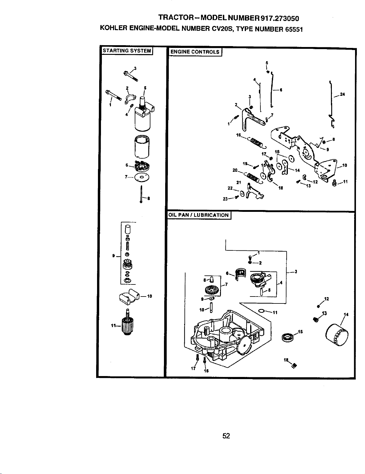
TRACTOR- MODEL NUMBER 917.273050
KOHLER ENGINE-MODEL NUMBER CV20S, TYPE NUMBER 65551
STARTING SYSTEM I
2 S
7-Q
ENGINE CONTROLS I
5
I
12
23_' _
OIL PAN / LUBRICATIONJ
17
O--2
_3
2
52
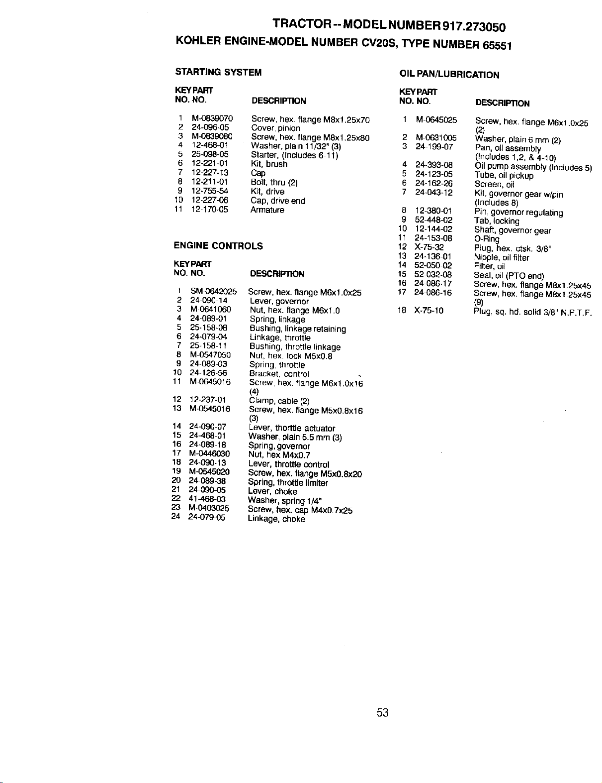
TRACTOR -- MODEL NUMBER 917.273050
KOHLER ENGINE-MODEL NUMBER CV2OS, TYPE NUMBER 65551
STARTING SYSTEM
OIL PAN/LUBRICATION
KEYPART KEYPART
NO. NO. DESCRIPTION NO. NO. DESCRIP'RON
1 M-0839070 Screw, hex. flange M8xl,25x70
2 24-096-05 Cover, pinion
3 M-0839080 Screw, hex. flange MBx1.25xB0
4 12-468-01 Washer, plain 11/32" (3)
5 25-098-05 Starter, (Includes 6-11)
6 12-221-0t Kit, brush
7 12-227-13 Cap
8 12-211_1 Bolt, thru (2)
9 12-755-54 Kit, drive
10 12-227-06 Cap, drive end
11 12-170-05 Armature
ENGINE CONTROLS
KEYPART
NO. NO. DESCRIPTION
Screw, hex. flange M6x1.0x25
Lever, governor
Nut, hex. flange M6xl.0
Spring, linkage
Bushing,linkage retaining
Linkage, throttle
Bushing, throttle linkage
Nut, hex. lock MSx0.8
Spring, throttle
Bracket, control
Screw, hex. flange M6xl.0x16
(4)
Clamp, cable (2)
Screw, hex. flange M5x0.8x16
(3)
Lever, thorttle actuator
Washer, plain 5.5 mm (3)
Spring, governor
Nut, hex M4x6.7
Lever, throttle control
Screw, hex. flange M5xO.Bx20
Spring,throttlellmiter
Lever, choke
Washer, spring 114"
Screw, hex. cap M4x0.7x25
Linkage, choke
1 SM_o42025
2 24-090 14
3 M-0641060
4 24-089-01
5 25-158-08
6 24-079-04
7 25-158-11
8 M-0547050
9 24-089-03
10 24-126-56
11 M-0645016
12 12-237-01
13 M-0545016
14 24-090-07
15 24-468-01
16 24-089-18
17 M-0446030
18 24-090-13
19 M-0545020
20 24-089<38
21 24-090-05
22 41--468-03
23 M-0403025
24 24-079-05
2
3
4
5
6
7
8
9
10
11
12
13
14
15
16
17
18
M-0645025
M-O631005
24-199-07
24-393-08
24-123-05
24-162-26
24-043-12
12-380-01
52-448-02
12-144-O2
24-153-08
X-75-32
24-136-01
52-050-02
52-032-08
24-086-17
24-086-16
X°75-10
Screw, hex. flange M6x1.0x2_
(2)
Washer, plain 6 mm (2)
Pan, oil assembly
(Includes 1,2, & 4-10)
Oil pump assembly (Includes
Tube, oil pickup
Screen, oil
Kit, governor gear w/pin
(Includes 8)
Pin, governor regulating
Tab, locking
Shaft, governor gear
O-Ring
Plug, flex. ctsk. 3/8"
Nipple, oil filter
Filter, oil
Seal, oil (PTO end)
Screw, hex. flange M8x1.25x,_
Screw, hex. flange M6x1.25xz
(9)
Plug, sq. hd. solid3/8" N.P.T.
53

TRACTOR-- MODEL NUMBER 917.273050
KOHLER ENGINE-MODEL NUMBER CV20S, TYPE NUMBER 65551
IGNITIONIELECTRICAL l
ill
14
AIR INTAKE J
SLOWER HOUSING AND SAFFLESJ
12-_+_
j
%--4
_2
_}---3
8
/"
Is
14
16
IS \
13
9
\
11
8
3
54
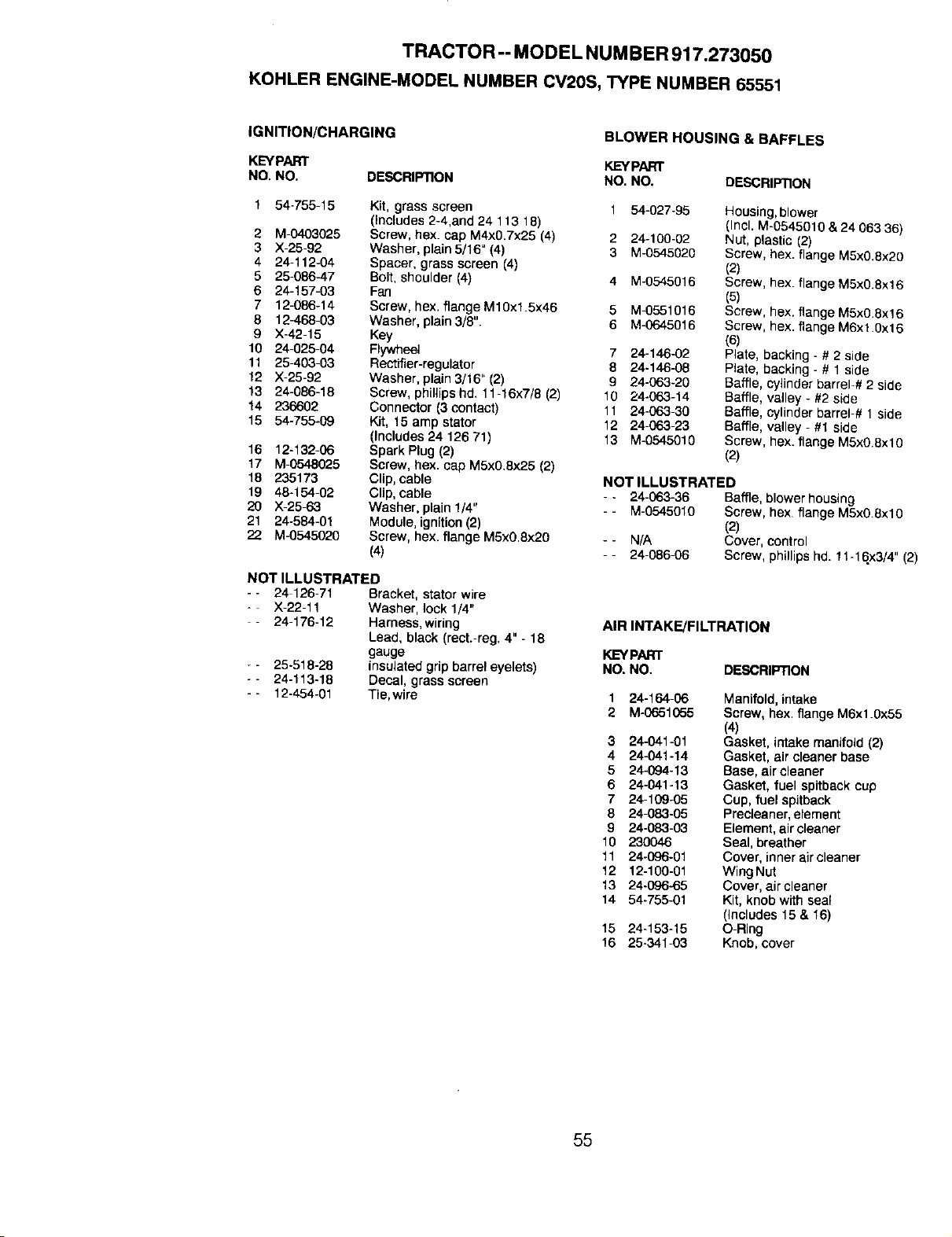
TRACTOR-- MODEL NUMBER917.273050
KOHLERENGINE-MODELNUMBERCV2OS,TYPENUMBER65551
IGNITION/CHARGING
KEYPART
NO. NO. DESCRIPTION
BLOWER HOUSING & BAFFLES
KEYPART
NO. NO. DESCRIPTION
1 54-755-15 Kit, grass screen 1 54-027-95
(Includes 2-4,and 24 113 18)
2 M-0403025 Screw, hex. cap M4x0.7x25 (4) 2 24-100-02
3 ;(-25-92 Washer, plain5/16" (4) 3 M-0545020
4 24-112-04 Spacer, grass screen (4)
5 25-086-47 Bolt, shoulder (4) 4 M-0545016
6 24-157-03 Fan
7 12-086-14 Screw, hex. flange M10x1.5x46 5 M-0551016
8 12-468-03 Washer, plain 3/8". 6 M-0645016
9 X-42-15 Key
10 24-025-04 Flywheel 7 24-146-02
11 25-403-63 Rectifier-regulator 8 24-146-08
12 X-25-92 Washer, plain 3!16" {2) 9 24-063-20
13 24-086-18 Screw, phillips hd. 11-16x7/8 (2) 10 24-063-14
14 286602 Connector (3 contact) 11 24-063-30
15 54-755-09 Kit, 15 amp starer 12 24-063-23
(Includes 24 126 71) 13 M-0545010
16 12-132-06 Spark Plug (2)
17 M-0548025 Screw, hex. cap M5x0.8x25 (2)
18 235173 Clip, cable
19 48-154-02 Clip, cable
20 X-25-63 Washer, plain1/4"
21 24-584-01 Module, ignition(2)
22 M-0545020 Screw, hex. flange M5x0.8x20
(4)
NOT ILLUSTRATED
- - 24 126-71 Bracket, stator wire
- X-22-11 Washer, lock 1/4"
- 24-176-12 Harness,wiring
Lead, black (rect.-reg. 4"- 18
gauge
- - 25-518-28 insulated grip barrel eyelets)
- - 24-113-18 Decal, grass screen
- - 12-454-01 Tie,wire
Housing, blower
(Incl. M-0545010 & 24 063 36)
Nut, plastic (2)
Screw, hex. flange M5x0.8x20
(2)
Screw, hex. flange M5x0.8x16
(5)
Screw, hex. flange M5x0.8x16
Screw, hex. flange M6x1.0x16
Plate, backing - # 2 side
Plate, backing - # 1 side
Baffle, cylinder barrel-# 2 side
Baffle, valley - #2 side
Baffle, cylinder barrel-# 1 side
Baffle, valley - #1 side
Screw, hex. flange M5x0.8xl0
(2)
NOT ILLUSTRATED
-. 24-063-36 Baffle,blowerhousing
- - M-0545010 Screw,hex flangeM5x0.8xt9
(2)
- - N/A Cover,control
- - 24-086-06 Screw,phillipshd.11-t6x3/4"(2)
AIR INTAKE/FILTRATION
KEYPART
NO.NO. DESCRIPTION
1 24-164-06 Manifold, intake
2 M-0651055 Screw, hex. 11angeM6x1.0x55
(4)
3 24-041-01 Gasket, Intake manifold (2)
4 24-041-14 Gasket, air cleaner base
5 24-094-13 Base, air cleaner
6 24-041-13 Gasket, fuel spitbackcup
7 24-109-05 Cup, fuel spitback
8 24_83-05 Precleaner, element
9 24-083-03 Element, air cleaner
10 230046 Seal, breather
11 24-096-01 Cover, innerair cleaner
12 12-100-01 Wing Nut
13 24-096-65 Cover, air cleaner
14 54-755-01 Kit, knob with seal
(Includes 15 & 16)
15 24-153-15 O-Ring
16 25-341-03 Knob, cover
55
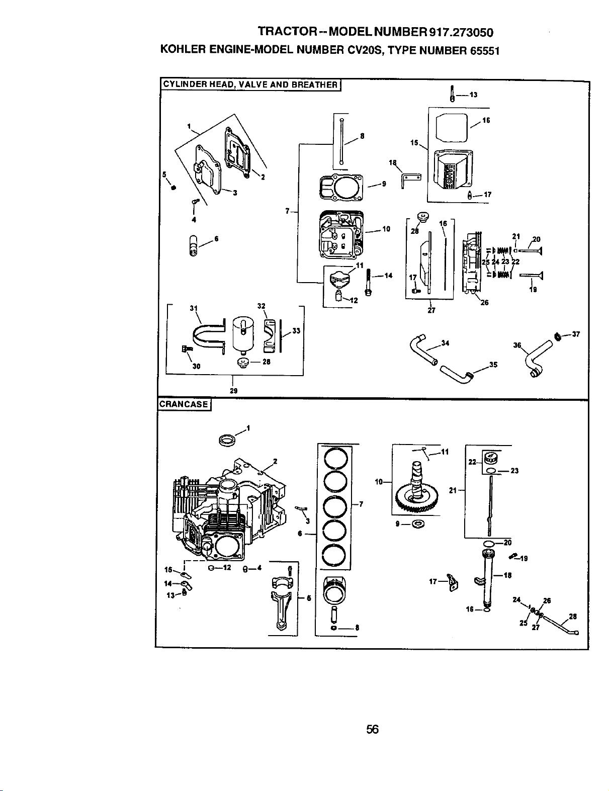
TRACTOR -- MODEL NUMBER 917.273050
KOHLER ENGINE-MODEL NUMBER CV20S, TYPE NUMBER 65551
CYLINDER HEAD, VALVE AND BREATHER I
\2
7-
,\
2 _
30 _ -- 28
I
29
CRANCASEJ
14--=_
O--12 g--4
iS--
!
V
V
-7
v
v
A
V
0--8
I D13
[_jls
25 _.423 22
_ 2s
27
56
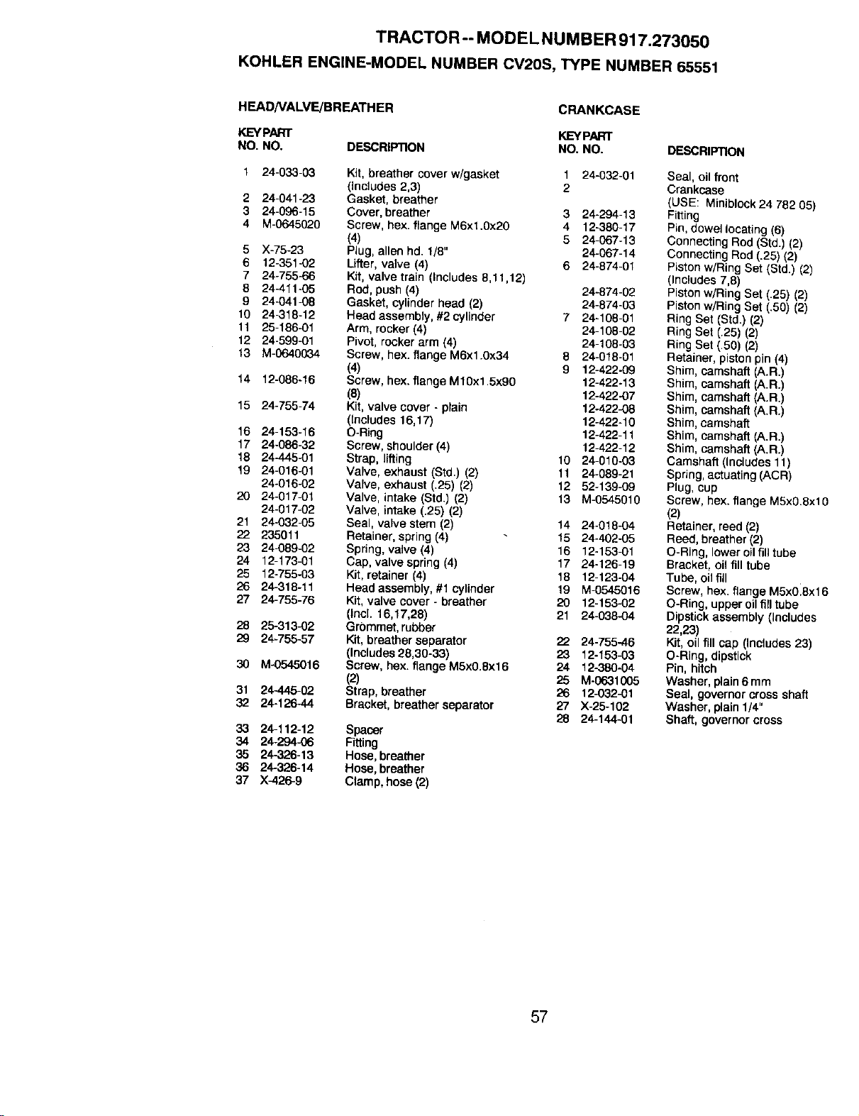
TRACTOR -- MODEL NUMBER 917.273050
KOHLER ENGINE-MODEL NUMBER CV2OS, TYPE NUMBER 65551
HEADNALVE/BREATHER
KEYPART
NO, NO. DESCRIPTION
CRANKCASE
KEYPART
NO. NO. DESCRIPTION
1 24-033-03 Kit, breather cover w/gasket 1 24-032-01
(includes 2,3) 2
2 24-041-23 Gasket, breather
3 24-096-15 Cover, breather 3 24-294-13
4 M-0645020 Screw, hex. flange M6xl.0x20 4 12-380-17
(4) 5 24_67-13
5 X-75-23 Plug, allen hd. 1/8" 24-067-14
6 12-351-02 Lifter, valve (4) 6 24-874-01
7 24-755-66 Kit, valve train (Includes 8,11,12)
8 24411-05 Rod, push (4) 24-874-02
9 24-041-08 Gasket, cytinderhead (2) 24-674-03
10 24_318-12 Head assembly, #2 cylinder 7 24-108-01
11 25-186-01 Arm, rocker (4) 24-108-02
12 24-599-01 Pivot, rocker arm (4) 24-108-03
13 M-0640034 Screw, hex. flange M6x1.0x34 8 24-018-01
(4) 9 12-422-09
14 12-088-16 Screw, hex. flange M10xt .5x90 12-422-13
(8) 12-422-07
15 24-755-74 Kit, valve cover - plain 12-422-08
(Includes 16,17) 12-422-10
16 24-153-16 O-Ring 12o422-11
17 24-086-32 Screw, shoulder(4) 12o422-12
18 24-445-01 Strap, lifting 10 24-010-03
19 24-016-01 Valve, exhaust (Std.) (2) 11 24-089-21
24-016-02 Valve, exhaust (.25) (2) 12 52-139-09
20 24-017-01 Valve, intake (Std.) (2) 13 M-0545010
24-017-02 Valve, intake (.25) (2)
21 24-032-05 Seal, valve stem (2) 14 24-018-04
22 235011 Retainer, spring(4) 15 24-402-05
23 24-089-02 Spring,valve (4) 16 12-153-01
24 12-173-01 Cap, valve spring (4) 17 24-126-19
25 12-755-03 Kit, retainer (4) 18 12-123-04
26 24-318-11 Head assembly,#1 cylinder 19 M-0545016
27 24-755-76 Kit, valve cover - breather 20 12-15302
(lncl. 16,17,28) 21 24-038-04
28 25-313-02 Grommet,rubber
29 24-755-57 Kit, breather separator 22 24-755-46
(Includes 28,30-33) 23 12-153-03
30 M-0545016 Screw, hex. flange M5x0.8x16 24 12_80-04
(2) 25 M-0631005
31 24-445-02 Strap, breather 26 12-032-01
32 24-126-44 Bracket, breather separator 27 X-25-102
28 24-144-01
33 24-112-12 Spacer
34 24-294-06 Fitting
35 24-326-13 Hose, breather
36 24-326-14 Hose, breather
37 X-426-9 Clamp, hose (2)
Seal, oil front
Crankcase
(USE: Miniblock24 782 05)
Fitting
Pin,dowel locating (6)
Connecting Rod (Std.) (2)
Connecting Rod (.25) (2)
Pistonw/Ring Set (Std.) (2)
(Includes 7,8)
Piston w/Ring Set (.25) (2)
Pistonw(Ring Set (.50) (2)
Ring Set (Std.) (2)
Ring Set (.25) (2)
Ring Set (.50) (2)
Retainer, piston pin (4)
Shim, camshaft (A.R.)
Shim, camsh_'_ (A.R.)
Shim, camshaft (A.R.)
Shim, camshaft (A.R.)
Shim, camshaft
Shim, camshaft (A.R.)
Shim, camshaft (A.R.)
Camshaft (Includes 11)
Spring, actuating (ACR)
Plug, cup
Screw, hex. flange M5x0.8xl0
(2)
Retainer, reed (2)
Reed, breather (2)
O-Ring, lower oil fill tube
Bracket, oil fill tube
Tube, oil fill
Screw, hex. flange M5x018x16
O-Ring, upper oilfill tube
Dipstick assembly (Includes
22,23)
Kit, oil fill cap (thc_udes23)
O-Ring, dipstick
Pin, hitch
Washer, plain 6 mm
Seal, governor cross shaft
Washer, plain 1/4"
Shaft, governorcross
57
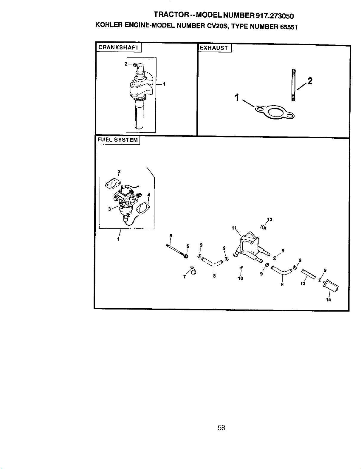
TRACTOR -- MODEL NUMBER 917.273050
KOHLER ENGINE-MODEL NUMBER CV20S, TYPE NUMBER 65551
CRANKSHAFT I
FUEL SYSTEM]
--1
EXHAUSTJ
2 \
/
/
1
11
5
\
/g i
7 8
\
2
9
58
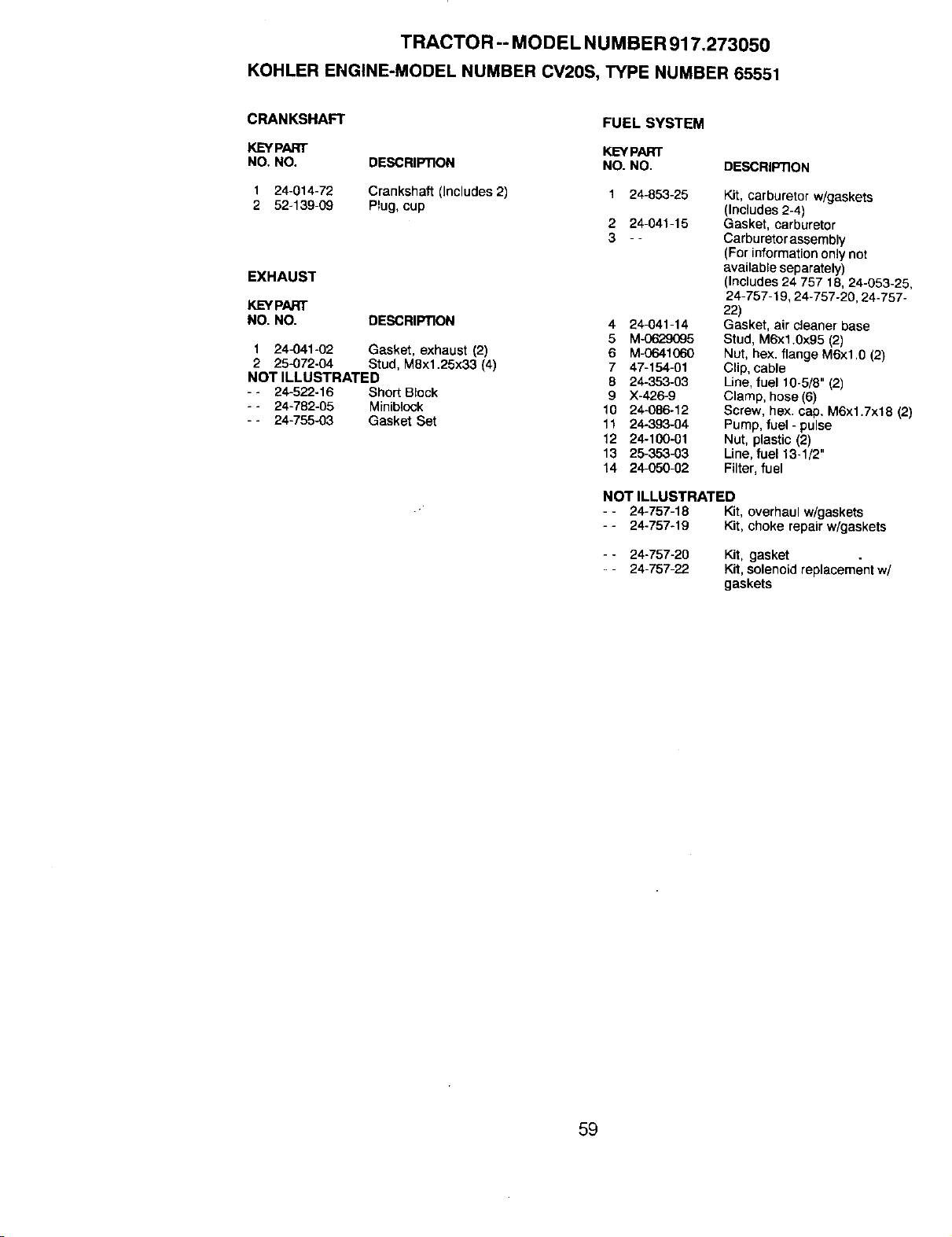
TRACTOR -- MODEL NUMBER 917.273050
KOHLER ENGINE-MODEL NUMBER CV20S, TYPE NUMBER 65551
CRANKSHAFT
KEYPART
NO. NO. DESCRIP_ON
1 24-014-72 Crankshaft (Includes2)
2 52-139-09 Plug, cup
EXHAUST
KEYPART
NO. NO. DESCRIPTION
1 244341-02 Gasket, exhaust (`2)
2 25.072-04 Stud, M8x1.28x33 (4)
NOT ILLUSTRATED
- - 24-522-16 Short Block
- - 24-782-05 Miniblock
- - 24-755-03 Gasket Set
FUEL SYSTEM
KEYPART
NO. NO. DESCRIPTION
1 24-853-25 Kit, carburetor w/gaskets
(Includes 2-4)
2 24-041-15 Gasket, carburetor
3 - - Carburetor assembly
(For information only not
available separately)
(Includes 24 757 18, 24-053-25,
24-757-'_9, 24-757-20, 24-757-
22)
4 24-041-14 Gasket, air cleaner base
5 M-0629095 Stud, M6xl.0x95 (2)
6 M.0641060 Nut, hex. fiange M6x1.0 (2)
7 47-154-01 Clip, cable
8 24-353-03 Line, fuel 10-5/8" (2)
9 X-426-9 Clamp, hose (6)
10 24-086-12 Screw, hex. ca_. M6xl.7x18 (2)
11 24-393434 Pump,fuel - pulse
12 24-100-01 Nut, plastic (2)
13 25-353.03 Line,fuel 13-1/2"
14 24-050.02 Fitter,fuel
NOT ILLUSTRATED
-- 24-757-18 Kit, overhaul w/gaskets
- - 24-757-19 Kit, choke repair w/gaskets
- - 24-757-20
- - 24-757-22
Kit, gasket
Kit, solenoid replacement w/
gaskets
59

60

61

62

SUGGESTED GUIDE FOR SIGHTING SLOPES FOR SAFE OPERATION
J "*
SIGHTING
GUIDE
ONLY RIDE UP AND DOWN HILL,
NOT ACROSS HILL
_1 _ Operate your Tractor up and down the face of slopes (not ]
i_|_ greater than 15°), never across the face. Make turns gradu-
I
i_|0 ally to prevent tipping or loss of control. Exercise extreme
:,!!1 caution when changing direction on slopes.

For in-home major brand repair service:
Call 24 hours a day, 7 days a week
1-800-4-MY-HOME s" (1-800-469-4663)
Para pedir servicio de reparacibn a domicilio
1-800-676-5811
In Canada for all your service and parts needs call
Au Canada pour tout le service ou les pieces
1-800-665-4455
For the repair or replacement parts you need:
Call 6 am - 11 pm CST, 7 days a week
PartsDirect
1-800-366-PART (1-800-366-7278)
Para ordenar piezas con entrega a domicilio
1-800-659-7084
For the location of a Sears Parts and Repair Center
in your area:
Call 24 hours a day, 7 days a week
1-800-488-1222
For information on purchasing a Sears Maintenance
Agreement or to inquire about an existing Agreement:
Call 9 am - 5 pro, Monday - Saturday
1-800-827-6655
167109 Rev. 4
8.23.99 RDiTR/RD Printed in U.S.A.