Loading ...
Loading ...
Loading ...
• To avoid snipe, gently push the board up while feed-
ing the work until the outfeed roller starts advancing
it
• Move to the rear and receive planed board by gently
pushing it up when the infeed roller looses contact
with the board
• When planing more than one board of the same
thickness, butt boards together to avoid snipe
• Snipe is more apparent when deeper cuts are taken
• Feed work in direction of grain Work fed against
grain will have chipped, splintered edges
Planer will operate best if kept in good condition and
properly adjusted
CHECK FOR WORN INSERTS
• Condition of inserts will affect precision of cut
Observe quality of cut which planer produces to
check condition of inserts
• Dull inserts will tear, rather than sever wood fibers
and produce fuzzy appearance
• Raised grain will occur when dull inserts pound on
wood that has varying density Raised edge will also
be produced where inserts have been nicked
• Inserts on this planer are indexable Keeping a spare
set of inserts on hand is recommended
CHANGING INSERTS
Refer to Figures 8-10
WARNING: Always turn planer OFF and disconnect
from power source before starting any maintenance
work
• Loosen and remove thumb screws from dust chute
and hood on the rear side of planer Remove chute
and hood
Figure 8 - Remove Dust Chute and Hood
• Loosen and remove three screws, washers and belt
guard
Figure9 - RemoveBelt Guard
• Carefully rotate belt towards you until cutterhead is
in desired position
• Put on heavy-duty gloves to protect your hands
CAUTION: Cutterhead inserts are very sharp and can
easily cut your hands ALWAYS use care and wear
gloves when handling inserts
• Use a vacuum to remove any sawdust or debris from
the insert to be rotated/replaced and also the area
surrounding the insert
• Loosen and remove Torx screw, remove insert and
then clean both parts and the space on cutterhead
they were removed from
NOTE: Insert, Torx screw and cutterhead must be
cleaned well Dust or debris trapped between the insert
and cutterhead can slightly raise the insert causing
insert to be out of height alignment with respect to the
other inserts
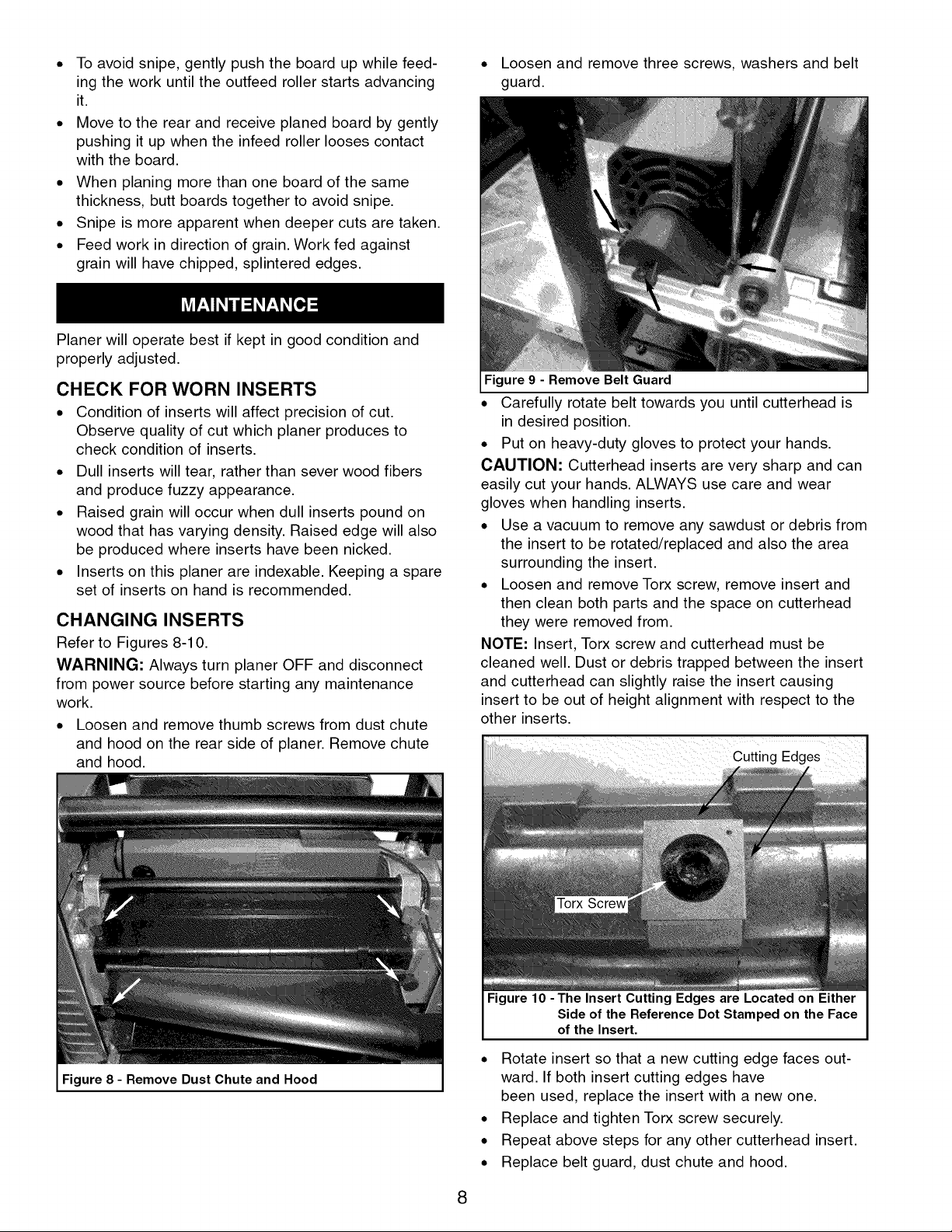
Figure 10 -The Insert Cutting Edges are Located on Either
Side of the Reference Dot Stamped on the Face
of the Insert.
• Rotate insert so that a new cutting edge faces out-
ward If both insert cutting edges have
been used, replace the insert with a new one
• Replace and tighten Torx screw securely
• Repeat above steps for any other cutterhead insert
• Replace belt guard, dust chute and hood
8
Loading ...
Loading ...
Loading ...