Loading ...
Loading ...
• Avoid accidental start-up. Make sure that the switch
is in the OFF position before plugging in.
• Do not force tool. It will work most efficiently at the
rate for which it was designed.
• Keep hands away from moving parts and cutting
surfaces.
• Never leave tool running unattended. Turn the power
off and do not leave tool until it comes to a complete
stop.
• Do not overreach. Keep proper footing and balance.
• Never stand on tool. Serious injury could occur if tool is
tipped or if blade is unintentionally contacted.
• Know your tool. Learn the tool's operation, applica-
tion and specific limitations.
• Use recommended accessories (refer to page 13).
Use of improper accessories may cause risk of
injury to persons.
• Handle workpiece correctly. Protect hands from pos-
sible injury.
• Turn machine off if it jams. Blade jams when it digs
too deeply into workpiece. (Motor force keeps it
stuck in the work.)
• Always keep drive, cutterhead and blade guards in
place and in proper operating condition.
• Feed work into blade or cutter against direction of
rotation.
CAUTION: Think safety! Safety is a combination of
operator common sense and alertness at all times
when tool is being used.
WARNING: Do not attempt to operate tool until it is
completely assembled according to the instructions.
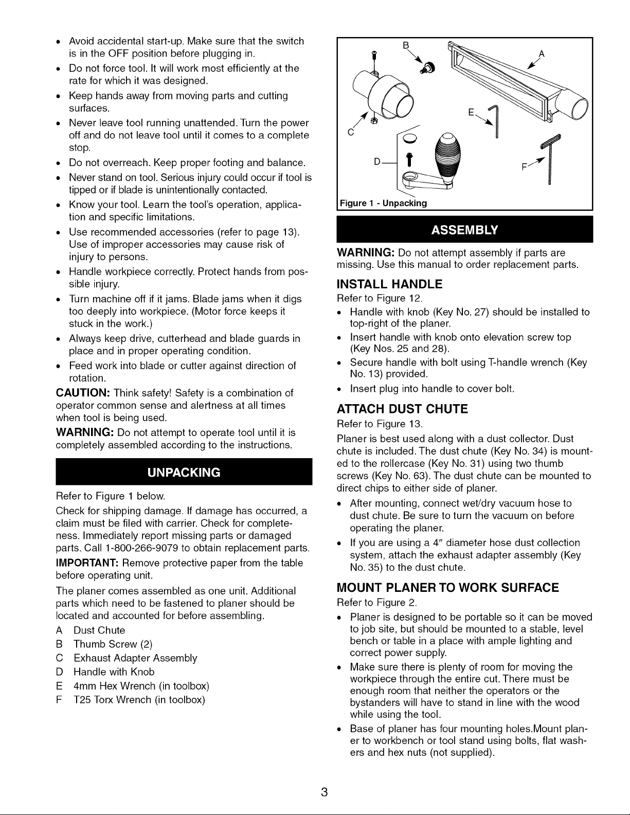
Refer to Figure 1 below.
Check for shipping damage. If damage has occurred, a
claim must be filed with carrier. Check for complete-
ness. Immediately report missing parts or damaged
parts. Call 1-800-266-9079 to obtain replacement parts.
IMPORTANT: Remove protective paper from the table
before operating unit.
The planer comes assembled as one unit. Additional
parts which need to be fastened to planer should be
located and accounted for before assembling.
A Dust Chute
B Thumb Screw (2)
C Exhaust Adapter Assembly
D Handle with Knob
E 4mm Hex Wrench (in toolbox)
F T25 Torx Wrench (in toolbox)
B
C
Figure 1 - Unpacking
A
WARNING: Do not attempt assembly if parts are
missing. Use this manual to order replacement parts.
INSTALL HANDLE
Refer to Figure 12.
• Handle with knob (Key No. 27) should be installed to
top-right of the planer.
• Insert handle with knob onto elevation screw top
(Key Nos. 25 and 28).
• Secure handle with bolt using T-handle wrench (Key
No. 13) provided.
• Insert plug into handle to cover bolt.
ATTACH DUST CHUTE
Refer to Figure 13.
Planer is best used along with a dust collector. Dust
chute is included. The dust chute (Key No. 34) is mount-
ed to the rollercase (Key No. 31) using two thumb
screws (Key No. 63). The dust chute can be mounted to
direct chips to either side of planer.
• After mounting, connect wet/dry vacuum hose to
dust chute. Be sure to turn the vacuum on before
operating the planer.
• If you are using a 4" diameter hose dust collection
system, attach the exhaust adapter assembly (Key
No. 35) to the dust chute.
MOUNT PLANER TO WORK SURFACE
Refer to Figure 2.
• Planer is designed to be portable so it can be moved
to job site, but should be mounted to a stable, level
bench or table in a place with ample lighting and
correct power supply.
• Make sure there is plenty of room for moving the
workpiece through the entire cut. There must be
enough room that neither the operators or the
bystanders will have to stand in line with the wood
while using the tool.
• Base of planer has four mounting holes.Mount plan-
er to workbench or tool stand using bolts, flat wash-
ers and hex nuts (not supplied).
3
Loading ...
Loading ...
Loading ...