Home
Bookmarks
Home
Chamberlain
Chamberlain G801CB-P User Manual
Page 28
Chamberlain G801CB-P
User Manual - Page 28
For G801CB-P.
PDF File Manual
,
116 pages
,
Read Online
|
Download pdf file
More photos
Unpacking
Safety Information
Quick Start
Preparing Tools and Components
Installing a Processor
Installing DDR4 memory
Connecting the Front Panel Header
Installing the Motherboard
Installing SATA Drives
Installing a Graphics Card
Connecting Peripheral Devices
Connecting the Power Connectors
Power On
Specifications
JCORSAIR1 Connector Specification
Block Diagram
Rear I/O Panel
LAN Port LED Status Table
Audio Ports Configuration
Realtek HD Audio Manager
Overview of Components
Processor Socket
DIMM Slots
PCI_E1~5: PCIe Expansion Slots
M2_1~2: M.2 Slots (Key M)
SATA1~8: SATA 6Gb/s Connectors
JFP1, JFP2: Front Panel Connectors
CPU_PWR1~2, ATX_PWR1: Power Connectors
JUSB1~2: USB 2.0 Connectors
JUSB3~4: USB 3.1 Gen1 Connectors
CPU_FAN1, PUMP_FAN1, SYS_FAN1~4: Fan Connectors
JAUD1: Front Audio Connector
JCI1: Chassis Intrusion Connector
JTPM1: TPM Module Connector
JBAT1: Clear CMOS (Reset BIOS) Jumper
JRGB1~2, JRAINBOW1: RGB LED connectors
JCORSAIR1: CORSAIR Connector
Onboard LEDs
DIMM LEDs
PCIe x16 slot LEDs
XMP LED
EZ Debug LED
BIOS Setup
Entering BIOS Setup
Resetting BIOS
Updating BIOS
EZ Mode
Advanced Mode
SETTINGS
Advanced
Boot
Security
Save & Exit
OC
M-FLASH
OC PROFILE
HARDWARE MONITOR
Software Description
Installing Windows® 10
Installing Drivers
Installing Utilities
APP MANAGER
LIVE UPDATE 6
COMMAND CENTER
GAMING APP
X-BOOST
MYSTIC LIGHT
MYSTIC LIGHT PARTY
SMART TOOL
RAMDISK
GAMING LAN MANAGER
Nahimic 2.5
RAID Configuration
Using AMD RAID Controller BIOS Configuration Utility
Initialize Disks
Create Arrays
Delete Arrays
Swap Arrays
Manage Spares
Change the Controller Options
Booting the system from an array
Pausing the boot sequence for warning messages
Change the Staggered Spinup Count
Using UEFI to create a 2.2TB RAID
Installing RAID Driver
Troubleshooting
Regulatory Notices
CPU_FAN1, PUMP_FAN1, SYS_FAN1~4: Fan Connectors
CPU_PWR1~2, ATX_PWR1: Power Connectors
DIMM Slots
JAUD1: Front Audio Connector
JBAT1: Clear CMOS (Reset BIOS) Jumper
JCI1: Chassis Intrusion Connector
JCORSAIR1: CORSAIR Connector
JFP1, JFP2: Front Panel Connectors
JRGB1~2, JRAINBOW1: RGB LED connectors
JTPM1: TPM Module Connector
JUSB1~2: USB 2.0 Connectors
JUSB3~4: USB 3.1 Gen1 Connectors
M2_1~2: M.2 Slots (Key M)
PCI_E1~5: PCIe Expansion Slots
Processor Socket
SATA1~8: SATA 6Gb/s Connectors
Page 28/116
Page 1
Page 2
Page 3
Page 4
Page 5
Page 6
Page 7
Page 8
Page 9
Page 10
Page 11
Page 12
Page 13
Page 14
Page 15
Page 16
Page 17
Page 18
Page 19
Page 20
Page 21
Page 22
Page 23
Page 24
Page 25
Page 26
Page 27
Page 28
Page 29
Page 30
Page 31
Page 32
Page 33
Page 34
Page 35
Page 36
Page 37
Page 38
Page 39
Page 40
Page 41
Page 42
Page 43
Page 44
Page 45
Page 46
Page 47
Page 48
Page 49
Page 50
Page 51
Page 52
Page 53
Page 54
Page 55
Page 56
Page 57
Page 58
Page 59
Page 60
Page 61
Page 62
Page 63
Page 64
Page 65
Page 66
Page 67
Page 68
Page 69
Page 70
Page 71
Page 72
Page 73
Page 74
Page 75
Page 76
Page 77
Page 78
Page 79
Page 80
Page 81
Page 82
Page 83
Page 84
Page 85
Page 86
Page 87
Page 88
Page 89
Page 90
Page 91
Page 92
Page 93
Page 94
Page 95
Page 96
Page 97
Page 98
Page 99
Page 100
Page 101
Page 102
Page 103
Page 104
Page 105
Page 106
Page 107
Page 108
Page 109
Page 110
Page 111
Page 112
Page 113
Page 114
Page 115
Page 116
Contents
Table of Contents
Search
Previous
Next
Troubleshooting
Bookmarks
Loading ...
Loading ...
Loading ...
28
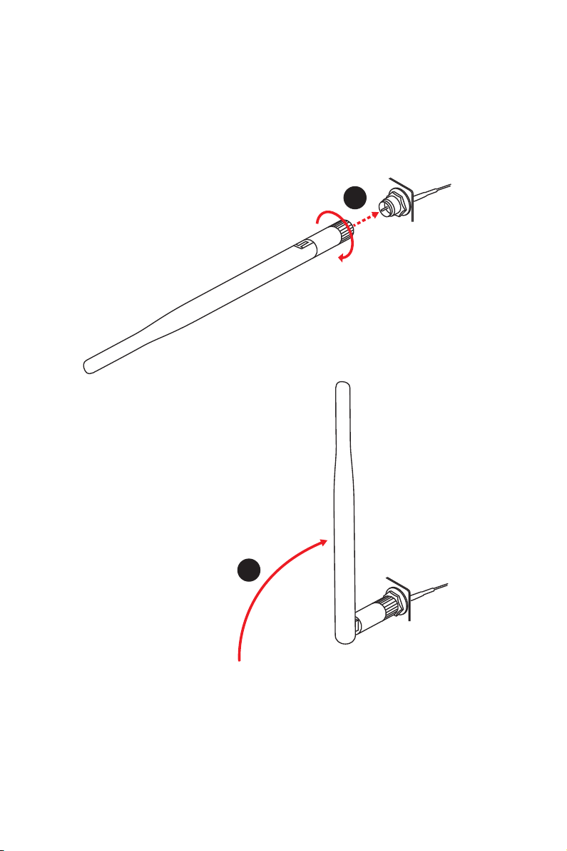
Rear I/O Panel
Installin
g antennas (
optional)
1.
Scr
ew the antennas tight to the antenna c
onnectors as sho
wn below
.
2.
Orient the antennas.
1
2
Loading ...
Loading ...
Loading ...
File type: PDF
File name: 78696797_g801cb-p.pdf
File size: 3.66 MB
File Language: English
Pages: 116
Author: Chamberlain
File created: 2022-05-18
Published: 2022-06-19
Updated: 2023-05-08
Download File
Table of Contents
×
Unpacking
1
Safety Information
3
Quick Start
4
Preparing Tools and Components
4
Installing a Processor
5
Installing DDR4 memory
7
Connecting the Front Panel Header
8
Installing the Motherboard
9
Installing SATA Drives
10
Installing a Graphics Card
11
Connecting Peripheral Devices
12
Connecting the Power Connectors
13
Power On
14
Specifications
18
JCORSAIR1 Connector Specification
23
Block Diagram
24
Rear I/O Panel
25
LAN Port LED Status Table
25
Audio Ports Configuration
25
Realtek HD Audio Manager
26
Overview of Components
29
Processor Socket
31
DIMM Slots
32
PCI_E1~5: PCIe Expansion Slots
33
M2_1~2: M.2 Slots (Key M)
36
SATA1~8: SATA 6Gb/s Connectors
37
JFP1, JFP2: Front Panel Connectors
37
CPU_PWR1~2, ATX_PWR1: Power Connectors
38
JUSB1~2: USB 2.0 Connectors
39
JUSB3~4: USB 3.1 Gen1 Connectors
39
CPU_FAN1, PUMP_FAN1, SYS_FAN1~4: Fan Connectors
40
JAUD1: Front Audio Connector
41
JCI1: Chassis Intrusion Connector
41
JTPM1: TPM Module Connector
42
JBAT1: Clear CMOS (Reset BIOS) Jumper
42
JRGB1~2, JRAINBOW1: RGB LED connectors
43
JCORSAIR1: CORSAIR Connector
44
Onboard LEDs
45
DIMM LEDs
45
PCIe x16 slot LEDs
45
XMP LED
45
EZ Debug LED
46
BIOS Setup
47
Entering BIOS Setup
47
Resetting BIOS
48
Updating BIOS
48
EZ Mode
49
Advanced Mode
51
SETTINGS
52
Advanced
52
Boot
57
Security
57
Save & Exit
59
OC
60
M-FLASH
65
OC PROFILE
66
HARDWARE MONITOR
67
Software Description
68
Installing Windows® 10
68
Installing Drivers
68
Installing Utilities
68
APP MANAGER
69
LIVE UPDATE 6
70
COMMAND CENTER
72
GAMING APP
76
X-BOOST
81
MYSTIC LIGHT
83
MYSTIC LIGHT PARTY
87
SMART TOOL
91
RAMDISK
93
GAMING LAN MANAGER
94
Nahimic 2.5
96
RAID Configuration
101
Using AMD RAID Controller BIOS Configuration Utility
101
Initialize Disks
103
Create Arrays
104
Delete Arrays
105
Swap Arrays
106
Manage Spares
107
Change the Controller Options
108
Booting the system from an array
108
Pausing the boot sequence for warning messages
108
Change the Staggered Spinup Count
109
Using UEFI to create a 2.2TB RAID
110
Installing RAID Driver
111
Troubleshooting
112
Regulatory Notices
113
CPU_FAN1, PUMP_FAN1, SYS_FAN1~4: Fan Connectors
40
CPU_PWR1~2, ATX_PWR1: Power Connectors
38
DIMM Slots
32
JAUD1: Front Audio Connector
41
JBAT1: Clear CMOS (Reset BIOS) Jumper
42
JCI1: Chassis Intrusion Connector
41
JCORSAIR1: CORSAIR Connector
44
JFP1, JFP2: Front Panel Connectors
37
JRGB1~2, JRAINBOW1: RGB LED connectors
43
JTPM1: TPM Module Connector
42
JUSB1~2: USB 2.0 Connectors
39
JUSB3~4: USB 3.1 Gen1 Connectors
39
M2_1~2: M.2 Slots (Key M)
36
PCI_E1~5: PCIe Expansion Slots
33
Processor Socket
31
SATA1~8: SATA 6Gb/s Connectors
37
Search:
×
Search