FilterQuick
™
FQG30
Gas Fryer
Installation, Operation and Maintenance Manual
This manual is updated as new information and models are released. Visit our website for the latest manual.
Part Number: FRY_IOM_8197052 06/2015
*8197052*
FOR YOUR SAFET
Y
Do Not Store or use gasoline or other
flammable vapors and liquids in the vicinity
of this or any other appliance.
OriginalInstructions
CAUTION
READTHEINSTRUCTIONSBEFOREUSINGTHEFRYER.
ii
NOTICE
IF, DURING THE WARRANTY PERIOD, THE CUSTOMER USES A PART FOR THIS MANITOWOC FOOD SERVICE
EQUIPMENT OTHER THAN AN UNMODIFIED NEW OR RECYCLED PART PURCHASED DIRECTLY FROM FRYMASTER
OR ANY OF ITS AUTHORIZED SERVICERS, AND/OR THE PART BEING USED IS MODIFIED FROM ITS ORIGINAL
CONFIGURATION, THIS WARRANTY WILL BE VOID. FURTHER, FRYMASTER AND ITS AFFILIATES WILL NOT BE
LIABLE FOR ANY CLAIMS, DAMAGES OR EXPENSES INCURRED BY THE CUSTOMER WHICH ARISE DIRECTLY OR
INDIRECTLY, IN WHOLE OR IN PART, DUE TO THE INSTALLATION OF ANY MODIFIED PART AND/OR PART
RECEIVED FROM AN UNAUTHORIZED SERVICER.
NOTICE
This appliance is intended for professional use only and is to be operated by qualified personnel only. A Frymaster
Factory Authorized Servicer (FAS) or other qualified professional should perform installation, maintenance, and
repairs. Installation, maintenance, or repairs by unqualified personnel may void the manufacturer’s warranty. See
Chapter 1 of this manual for definitions of qualified personnel.
NOTICE
This equipment must be installed in accordance with the appropriate national and local codes of the country and/or
region in which the appliance is installed. See NATIONAL CODE REQUIREMENTS in Chapter 2 of this manual for
specifics.
NOTICE TO U.S. CUSTOMERS
This equipment is to be installed in compliance with the basic plumbing code of the Building Officials and Code
Administrators International, Inc. (BOCA) and the Food Service Sanitation Manual of the U.S. Food and Drug
Administration.
NOTICE
Drawings and photos used in this manual are intended to illustrate operational, cleaning and technical procedures
and may not conform to onsite management operational procedures.
NOTICE
This appliance is intended to be used for commercial applications, for example in kitchens of restaurants, canteens,
hospitals and in commercial enterprises such as bakeries, butcheries, etc., but not for continuous mass production
of food.
NOTICE TO OWNERS OF UNITS EQUIPPED WITH CONTROLLERS
U.S.
This device complies with Part 15 of the FCC rules. Operation is subject to the following two conditions: 1) This
device may not cause harmful interference, and 2) This device must accept any interference received, including
interference that may cause undesired operation. While this device is a verified Class A device, it has been shown to
meet the Class B limits.
CANADA
This digital apparatus does not exceed the Class A or B limits for radio noise emissions as set out by the ICES-003
standard of the Canadian Department of Communications.
DANGER
Improper installation, adjustment, maintenance or service, and unauthorized alterations or modifications can cause
property damage, injury, or death. Read the installation, operating, and service instructions thoroughly before
installing or servicing this equipment. Only qualified service personnel may convert this appliance to use a gas other
than that for which it was originally configured.
DANGER
No structural material on the fryer should be altered or removed to accommodate placement of the fryer under a hood.
Questions? Call the Frymaster Service Hotline at 1-800-551-8633.
WARNING
After installation of a gas fryer and after any maintenance to the gas system of a gas fryer-manifold, valve, burners,
etc. – check for gas leaks at all connections. Apply a thick soapy solution to all connections and ensure there are no
bubbles. There should be no smell of gas.
NOTICE
The Commonwealth of Massachusetts requires any and all gas products to be installed by a licensed plumber or pipe
fitter.
iii
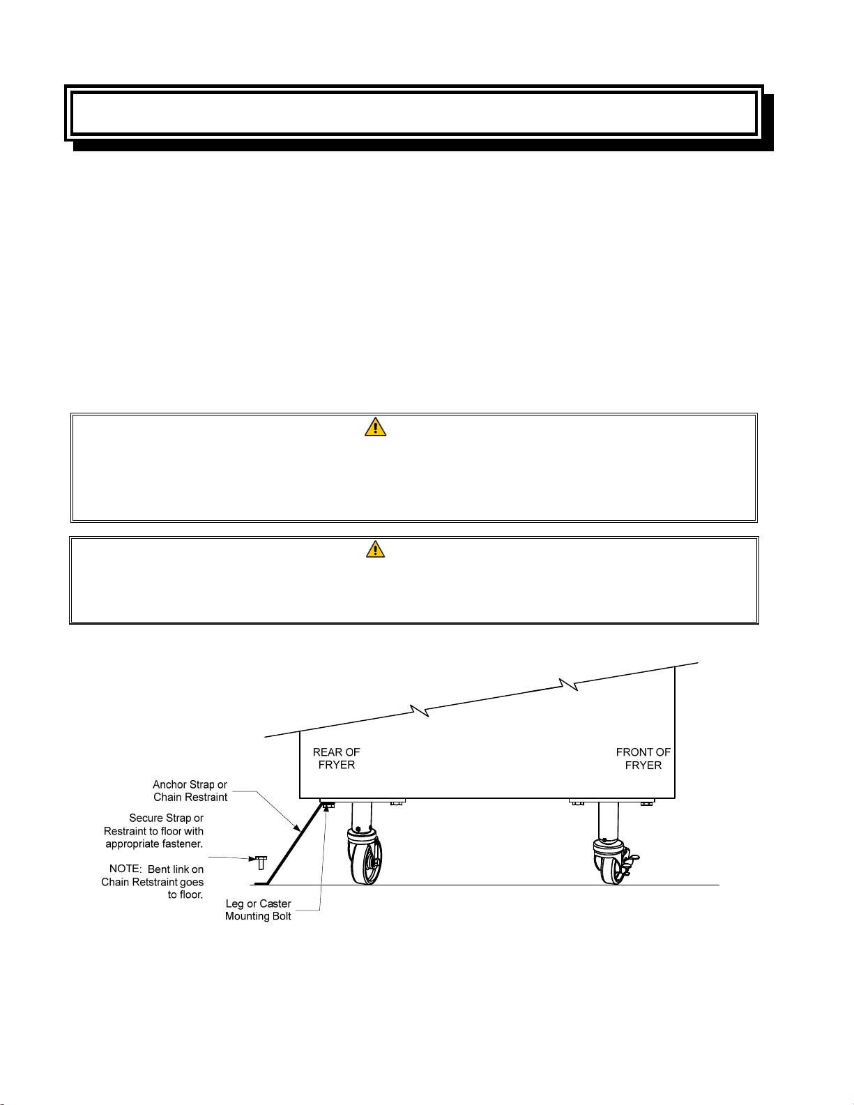
DANGER
Adequate means must be provided to limit the movement of this appliance without depending upon the gas line
connection. Single fryers equipped with legs must be stabilized by installing anchor straps. All fryers equipped with
casters must be stabilized by installing restraining chains. If a flexible gas line is used, an additional restraining cable
must be connected at all times when the fryer is in use.
CAUTION
No warranty is provided for any Frymaster fryer used in a mobile or marine installation or concession. Warranty
protection is only offered for fryers installed in accordance with the procedures described in this manual. Mobile,
marine or concession conditions of this fryer should be avoided to ensure optimum performance.
DANGER
The front ledge of the fryer is not a step! Do not stand on the fryer. Serious injury can result from slips or contact
with the hot oil.
DANGER
Do not store or use gasoline or other flammable liquids or vapors in the vicinity of this or any other appliance.
DANGER
Do not spray aerosols in the vicinity of this appliance while it is in operation.
DANGER
Instructions to be followed in the event the operator smells gas or otherwise detects a gas leak must be posted in a
prominent location. This information can be obtained from the local gas company or gas supplier.
DANGER
This product contains chemicals known to the state of California to cause cancer and/or birth defects or other
reproductive harm.
Operation, installation, and servicing of this product could expose you to airborne particles of glasswool or ceramic
fibers, crystalline silica, and/or carbon monoxide. Inhalation of airborne particles of glasswool or ceramic fibers is
known to the State of California to cause cancer. Inhalation of carbon monoxide is known to the State of California to
cause birth defects or other reproductive harm.
DANGER
The crumb tray in fryers equipped with a filter system must be emptied into a fireproof container at the end of frying
operations each day. Some food particles can spontaneously combust if left soaking in certain shortening material.
WARNING
Do not bang fry baskets or other utensils on the fryer’s joiner strip. The strip is present to seal the joint between the
fry vessels. Banging fry baskets on the strip to dislodge shortening will distort the strip, adversely affecting its fit. It
is designed for a tight fit and should only be removed for cleaning.
DANGER
Improper installation, adjustment, maintenance or service, and unauthorized alterations or modifications can cause
property damage, injury, or death. Read the installation, operating, and service instructions thoroughly before
installing or servicing this equipment.
NOTICE
The appliance must be installed and used in such a way that any water cannot contact the fat or oil.
DANGER
Keep all items out of drains. Closing actuators may cause damage or injury.
DANGER
Prior to movement, testing, maintenance and any repair on your Frymaster fryer; disconnect ALL electrical power
cords from the electrical power supply.
WARNING
Use caution and wear appropriate safety equipment to avoid contact with hot oil or surfaces that may cause severe
burns or injury.

iv
FilterQuick
™
FQG30 Series Gas Fryers
Installation and Operation Manual
TABLE OF CONTENTS
CHAPTER 1: General Information
1.1 Applicability and Validity ............................................................................................................................. 1-1
1.2 Safety Information ......................................................................................................................................... 1-1
1.3 Controller Information .................................................................................................................................. 1-2
1.4 European Community (CE) Specific Information ................................................................................ 1-2
1.5 Equipment Description ................................................................................................................................ 1-3
1.6 Installation, Operating, and Service Personnel .................................................................................... 1-3
1.7 Definitions ......................................................................................................................................................... 1-3
1.8 Shipping Damage Claim Procedure ........................................................................................................ 1-4
1.9 Reading the Model Numbers ..................................................................................................................... 1-5
1.10 Parts Ordering and Service Information ................................................................................................. 1-5
CHAPTER 2: Installation Instructions
2.1 General Installation Requirements ........................................................................................................... 2-1
2.1.1 Clearance and Ventilation .............................................................................................................. 2-1
2.1.2 National Code Requirements ........................................................................................................ 2-2
2.1.3 Electrical Grounding Requirements ........................................................................................... 2-3
2.1.4 Australian Requirements ................................................................................................................ 2-3
2.2 Caster/Leg Installation .................................................................................................................................. 2-3
2.3 Pre-Connection Preparations ..................................................................................................................... 2-4
2.4 Connection to Gas Line ................................................................................................................................ 2-6
2.5 Converting to another Gas Type ............................................................................................................... 2-9
2.6 Positioning the Fryer ................................................................................................................................... 2-10
2.7 Installing the JIB Cradle .............................................................................................................................. 2-11
CHAPTER 3: Operating Instructions
3.1 Controller Operation and Programming ................................................................................................ 3-2
3.2 Equipment Setup and Start-Up Procedures .......................................................................................... 3-2
3.2.1 Setup ..................................................................................................................................................... 3-2
3.2.2 Lighting the Fryer ............................................................................................................................. 3-3
3.3 Shutting the Fryer Down ............................................................................................................................. 3-4
3.4 Oil Attendant
®
Automatic Topoff .............................................................................................................. 3-5
3.4.1 Install the Oil Reservoir ................................................................................................................... 3-5
3.4.2 Routine Oil Changes ........................................................................................................................ 3-6
CHAPTER 4: Filtration Instructions
4.1 Introduction ..................................................................................................................................................... 4-1
4.2 Preparing the Filtration System for Use with Paper or Pad ............................................................ 4-1
4.3 FilterQuick
™
with Fingertip Filtration ....................................................................................................... 4-2
4.4 Troubleshooting the FilterQuick
™
with Fingertip Filtration ............................................................. 4-3
4.4.1 Incomplete Filtration ....................................................................................................................... 4-3
4.4.2 Clogged Drain Error ......................................................................................................................... 4-4
4.5 Filter Busy .......................................................................................................................................................... 4-4
4.6 Draining and Refilling Vats, and Disposing of Waste Oil .................................................................. 4-5

v
CHAPTER 5: Preventive Maintenance
5.1 Fryer Preventive Maintenance Checks and Service ............................................................................ 5-1
5.2 Daily Checks and Service .............................................................................................................................. 5-1
5.2.1 Inspect Fryer for Damage ................................................................................................................ 5-1
5.2.2 Clean Fryer Cabinet Inside and Out ............................................................................................. 5-1
5.2.3 Clean the FilterQuick Filtration System ...................................................................................... 5-1
5.2.4 Clean Filter Pan, Detachable Parts and Accessories ............................................................... 5-2
5.2.5 Clean Oil Level Sensor ....................................................................................................................... 5-2
5.3 Weekly Checks and Service ......................................................................................................................... 5-2
5.3.1 Drain and Clean Frypot ..................................................................................................................... 5-2
5.3.2 Boiling out the Frypot ....................................................................................................................... 5-3
5.4 Monthly Checks and Service ....................................................................................................................... 5-3
5.4.1 Check FilterQuick™ Setpoint Accuracy ....................................................................................... 5-3
5.5 Quarterly Checks and Service ..................................................................................................................... 5-4
5.5.1 Replace the O-rings ........................................................................................................................... 5-4
5.6 Semi-Annual Checks and Service .............................................................................................................. 5-4
5.6.1 Clean Gas Valve Vent Tube .............................................................................................................. 5-4
5.6.2 Check Burner Manifold Pressure ................................................................................................... 5-4
5.7 Annual/Periodic System Inspection ......................................................................................................... 5-4
5.7.1 Fryer ........................................................................................................................................................ 5-4
5.7.2 FilterQuick™ Fingertip Filtration System .................................................................................... 5-5
5.7.3 Clean Combustion Air Blower Assembly .................................................................................... 5-6
CHAPTER 6: Operator Troubleshooting
6.1 Introduction ...................................................................................................................................................... 6-1
6.2 Troubleshooting .............................................................................................................................................. 6-2
6.2.1 Controller and Heating Problems ................................................................................................. 6-2
6.2.2 Error Message and Display Problems .......................................................................................... 6-3
6.2.3 Basket Lift Problems .......................................................................................................................... 6-3
6.2.4 Filtration Problems ............................................................................................................................. 6-4
6.2.5 Auto Top-Off Problems .................................................................................................................... 6-5
6.2.6 Error Log Codes ................................................................................................................................... 6-5
6.2.7 High Limit Test..................................................................................................................................... 6-6
APPENDIX A: Bulk Oil Instructions
APPENDIX B: Solid Shortening JIB Preparation Instructions
APPENDIX C: Solid Shortening Melting Unit Use Instructions
1-1
FILTERQUICK
™
FQG30 SERIES GAS FRYER
CHAPTER 1: GENERAL INFORMATION
1.1 Applicability and Validity
The FilterQuick™ FQG30 Series Gas Fryer, with SMART4U
®
technology, has been approved
by the European Union for sale and installation in the following EU countries: AT, BE, DE,
DK, ES, FI, FR, GB, IE, IT, LU, NL, NO, PT and SE.
This manual is applicable to and valid for all FilterQuick™ FQG30 Series Gas Fryers sold in
English-speaking countries, including those in the European Union. Where conflicts exist be-
tween instructions and information in this manual and local or national codes of the country in
which the equipment is installed, installation and operation shall comply with those codes.
This appliance is only for professional use and shall be used by qualified personnel only, as
defined in Section 1.7.
1.2 Safety Information
Before attempting to operate your unit, read the instructions in this manual thoroughly. Throughout
this manual, you will find notations enclosed in double-bordered boxes similar to the ones that
follow.
CAUTION
CAUTION boxes contain information about actions or conditions that may cause or result
in a malfunction of your system.
WARNING
WARNING boxes contain information about actions or conditions that may cause or result
in damage to your system, and which may cause your system to malfunction.
DANGER
DANGER boxes contain information about actions or conditions that may cause or result
in injury to personnel, and which may cause damage to your system and/or cause your
system to malfunction.
Your fryer is equipped with automatic safety features:
1. High temperature detection shuts off gas to the burner assembly should the controlling
thermostat fail.
NOTE: The Frymaster FilterQuick™ FQG30 fryer requires a start-up, demonstration
and training before normal restaurant operations can begin.
1-2
2. An optional safety switch built into the drain valve prevents burner ignition with the drain valve
even partially open.
1.3 Controller Information
FCC COMPLIANCE
This equipment has been tested and found to comply with the limits for a Class A digital device,
pursuant to Part 15 of the FCC rules. While this device is a verified Class A device, it has been
shown to meet the Class B limits. These limits are designed to provide reasonable protection against
harmful interference when the equipment is operated in a commercial environment. This equipment
generates, uses and can radiate radio frequency energy and, if not installed and used in accordance
with the instruction manual, may cause harmful interference to radio communications.
Operation of the equipment in a residential area is likely to cause harmful interference in which case
the user will be required to correct the interference at their own expense.
The user is cautioned that any changes or modifications not expressly approved by the party respon-
sible for compliance could void the user's authority to operate the equipment.
If necessary, the user should consult the dealer or an experienced radio and television technician for
additional suggestions.
The user may find the following booklet prepared by the Federal Communications Commission
helpful: "How to Identify and Resolve Radio-TV Interference Problems". This booklet is available
from the U.S. Government Printing Office, Washington, DC 20402, Stock No. 004-000-00345-4.
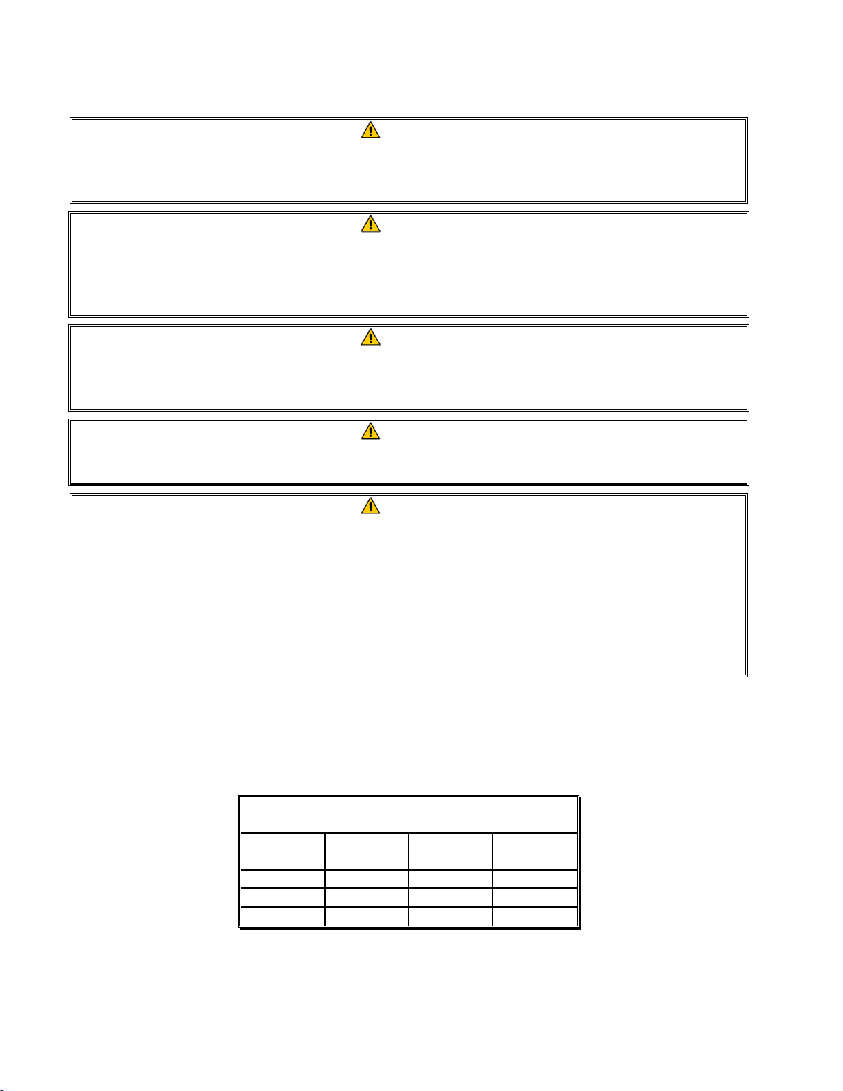
1.4 European Community (CE) Specific Information
The European Community (CE) has established certain specific standards regarding equipment of
this type. Whenever a conflict exists between CE and non-CE standards, the information or
instructions concerned are identified by means of shadowed boxes similar to the one below.
Non-CE Standard
for Incoming Gas Pressures
Type Minimum Maximum
6" W.C. 14" W.C.
Natural 1.49 kPa 3.49 kPa
14.68 mbar 34.72 mbar
11" W.C. 14" W.C.
LP 2.74 kPa 3.49 kPa
27.28 mbar 34.84 mbar

1-3
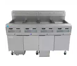
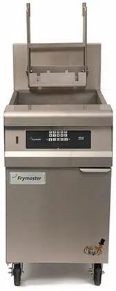
1.5 Equipment Description
FilterQuick™ FQG30 Series high-efficiency gas fryers employ a unique infrared burner system that
uses up to 43% less energy to cook the same volume as conventional open-burner fryers. Models in
this series include FQG variants. These models have a built-in FilterQuick™ fingertip filtration
system located under the leftmost fryer in a battery.
All FilterQuick™ FQG30 Series Gas fryers are of an open-frypot design with no tubes and have a
hand-sized opening into the cold zone, which makes cleaning the stainless frypot quick and easy.
Heating is supplied by a pair of infrared burner assemblies mounted on each side of the frypot.
Combustion air for the burners is supplied by a dedicated blower mounted on the front of the frypot.
FilterQuick™ FQG30 Series Gas fryers can be configured for natural gas, propane (LP), or
manufactured gas, as required by the customer.
Each frypot is equipped with a temperature probe for precise temperature control.
All FilterQuick™ FQG30 Series Gas fryers come standard with electronic ignition and melt cycle
mode. The FilterQuick™ FQG30 Series Gas fryers are controlled with a FilterQuick™ controller.
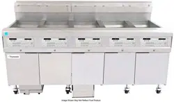
Fryers in this series come in full or split pot arrangements, and can be purchased as two, three or
four vat fryers.
All fryers in this series require an external source of AC electrical power. Units can be configured
for voltages ranging from 100 VAC to 240 VAC.
FilterQuick™ FQG30 Series fryers are shipped completely assembled. All fryers are shipped with a
package of standard accessories. Each fryer is adjusted, tested, and inspected at the factory before
crating for shipment.
1.6 Installation, Operating, and Service Personnel
Operating information for Frymaster equipment has been prepared for use by qualified and/or
authorized personnel only, as defined in Section 1.7. All installation and service on Frymaster
equipment must be performed by qualified, certified, licensed, and/or authorized installation
or service personnel, as defined in Section 1.7.
1.7 Definitions
QUALIFIED AND/OR AUTHORIZED OPERATING PERSONNEL
Qualified/authorized operating personnel are those who have carefully read the information in this
manual and have familiarized themselves with the equipment functions, or who have had previous
experience with the operation of the equipment covered in this manual.

1-4
QUALIFIED INSTALLATION PERSONNEL
Qualified installation personnel are individuals, firms, corporations, and/or companies which, either
in person or through a representative, are engaged in and are responsible for the installation of gas-
fired appliances. Qualified personnel must be experienced in such work, be familiar with all gas
precautions involved, and have complied with all requirements of applicable national and local
codes.
QUALIFIED SERVICE PERSONNEL
Qualified service personnel are those who are familiar with Frymaster equipment and who have been
authorized by Frymaster, L.L.C. to perform service on the equipment. All authorized service per-
sonnel are required to be equipped with a complete set of service and parts manuals, and to stock a
minimum amount of parts for Frymaster equipment. A list of Frymaster Factory Authorized Ser-
vicers (FAS’s) is located on the Frymaster website at www.frymaster.com/service. Failure to use
qualified service personnel will void the Frymaster warranty on your equipment.
1.8 Shipping Damage Claim Procedure
Your Frymaster equipment was carefully inspected and packed before leaving the factory. The
transportation company assumes full responsibility for safe delivery upon its acceptance of the
equipment for transport.
What to do if your equipment arrives damaged:
1. File a claim for damages immediately, regardless of the extent of damages.
2. Inspect for and record all visible loss or damage, and ensure that this information is noted on
the freight bill or express receipt and is signed by the person making the delivery.
3. Concealed loss or damage that was unnoticed until the equipment was unpacked should be
recorded and reported to the freight company or carrier immediately upon discovery. A
concealed damage claim must be submitted within 15 days of the date of delivery. Ensure that
the shipping container is retained for inspection.
Frymaster
DOES NOT ASSUME RESPONSIBILITY FOR DAMAGE OR LOSS
INCURRED IN TRANSIT.
1-5
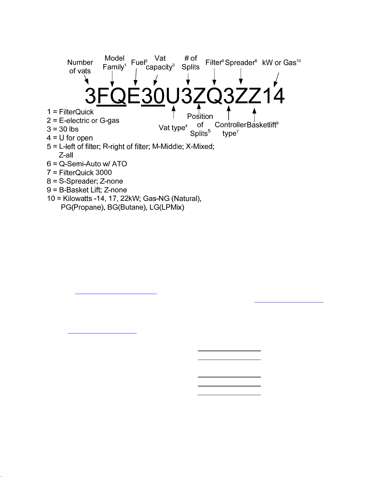
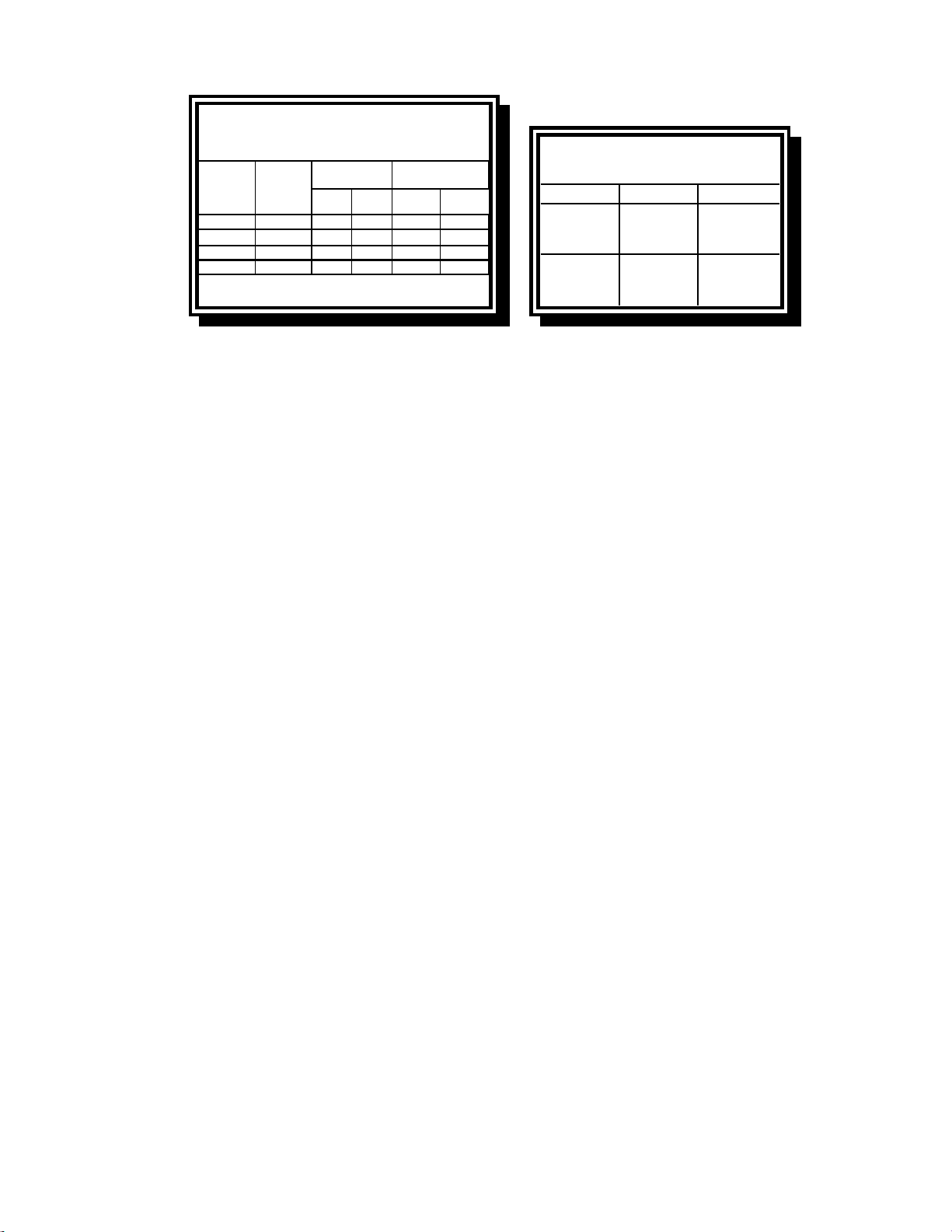
1.9 Reading Model Numbers
1.10 Parts Ordering and Service Information
In order to assist you quickly, the Frymaster Factory Authorized Servicer (FAS) or Service
Department representative requires certain information about your equipment. Most of this
information is printed on a data plate affixed to the inside of the fryer door. Part numbers are found
in the Service and Parts Manual. Parts orders may be placed directly with your local FAS or
distributor. A list of Frymaster Factory Authorized Servicers (FAS’s) is located on the Frymaster
website at www.frymaster.com/service. If you do not have access to this list, contact the Frymaster
Service Department at 1-800-551-8633 or 1-318-865-1711 or by e-mail: service@frymaster.com.
Service information may be obtained by contacting your local FAS/Distributor. Service may also be
obtained by calling the Frymaster Service Department at 1-800-551-8633 or 1-318-865-1711 or by
information ready:
Model Number:
Serial Number:
Type of Gas and
voltage:
Item Part Number:
Quantity Needed:
In addition to the model number, serial number, and type of gas, please be prepared to describe the
nature of the problem and have ready any other information that you think may be helpful in solving
your problem.
RETAIN AND STORE THIS MANUAL IN A SAFE PLACE FOR FUTURE USE.
2-1
FILTERQUICK
™
FQG30 SERIES GAS FRYER
CHAPTER 2: INSTALLATION INSTRUCTIONS
2.1 General Installation Requirements
Qualified, licensed, and/or authorized installation or service personnel, as defined in Section
1.7 of this manual, should perform all installation and service on Frymaster equipment.
Conversion of this appliance from one type of gas to another should only be performed by
qualified, licensed, and/or authorized installation or service personnel as defined in Section 1.7
of this manual.
Failure to use qualified, licensed, and/or authorized installation or service personnel (as de-
fined in Section 1.7 of this manual) to install, convert to another gas type or otherwise service
this equipment will void the Frymaster warranty and may result in damage to the equipment
or injury to personnel.
Where conflicts exist between instructions and information in this manual and local or nation-
al codes or regulations, installation and operation shall comply with the codes or regulations in
force in the country in which the equipment is installed.
DANGER
Building codes prohibit a fryer with its open tank of hot oil being installed beside an
open flame of any type, including those of broilers and ranges.
Upon arrival, inspect the fryer carefully for visible or concealed damage. (See Shipping Damage
Claim Procedure in Chapter 1.)
2.1.1 Clearance and Ventilation
The fryer(s) must be installed with a 6” (150 mm) clearance at both sides and back when installed
adjacent to combustible construction; no clearance is required when installed adjacent to
noncombustible construction. A minimum of 24” (600 mm) clearance should be provided at the
front of the fryer.
WARNING
Do not block the area around the base or under the fryers.
DANGER
No structural material on the fryer should be altered or removed to accommodate
placement of the fryer under a hood. Questions? Call the Frymaster Service Hotline
at 1-800-551-8633.
2-2
One of the most important considerations of efficient fryer operation is ventilation. Make sure the
fryer is installed so that products of combustion are removed efficiently, and that the kitchen
ventilation system does not produce drafts that interfere with burner operation.
The fryer flue opening must not be placed close to the intake of the exhaust fan, and the fryer must
never have its flue extended in a “chimney” fashion. An extended flue will change the combustion
characteristics of the fryer, causing longer recovery time. It also frequently causes delayed ignition.
To provide the airflow necessary for good combustion and burner operation, the areas surrounding
the fryer front, sides, and rear must be kept clear and unobstructed.
DANGER
This appliance must be installed with sufficient ventilation to prevent the occurrence
of unacceptable concentrations of substances harmful to the health of personnel in
the room in which it is installed.
Fryers must be installed in an area with an adequate air supply and adequate ventilation. Adequate
distances must be maintained from the flue outlet of the fryer to the lower edge of the ventilation
filter bank. Filters should be installed at an angle of 45º. Place a drip tray beneath the lowest edge
of the filter. For U.S. installation, NFPA standard No. 96 states, “A minimum distance of 18 in.
(450 mm) should be maintained between the flue outlet and the lower edge of the grease filter.”
Frymaster recommends that the minimum distance be 24 in. (600 mm) from the flue outlet to the
bottom edge of the filter when the appliance consumes more than 120,000 BTU per hour.
For installations in the United States, information on construction and installation of ventilating
hoods can be found in the NFPA standard cited above. A copy of the standard may be obtained
from the National Fire Protection Association, Battery March Park, Quincy, MA 02269.
2.1.2 National Code Requirements
The type of gas for which the fryer is equipped is stamped on the data plate attached to the inside of
the fryer door. Connect a fryer stamped “NAT” only to natural gas, those stamped “PRO” only to
propane gas, and those stamped “MFG” only to manufactured gas.
Installation shall be made with a gas connector that complies with national and local codes, and,
where applicable, CE codes. Quick-disconnect devices, if used, shall likewise comply with national,
local, and, if applicable, CE codes. In the absence of local codes, installation must conform to the
national Fuel Gas Code, ANSI Z223.1/NFPA 54 or the Natural Gas and Propane Installation code,
CSA B149.1, as applicable including:
1. The appliance and its individual shutoff valve must be disconnected form the gas supply piping
system during any pressure testing of the system at test pressures in excess of ½ psi (3.5 kPa).
2. The appliance must be isolated from the gas supply piping system by closing its individual
manual shutoff valve during any pressure testing of the gas supply piping system at test
pressures equal to or less than ½ psi (3.5 kPa).
2-3
2.1.3 Electrical Grounding Requirements
All electrically operated appliances must be grounded in accordance with all applicable national and
local codes, and, where applicable, CE codes. In the absence of local codes, the appliance must be
grounded in accordance with National Electrical Code, ANSI/NFPA 70, or the Canadian Electrical
Code, CSA C22.2, as applicable. All units (cord connected or permanently connected) should be
connected to a grounded power supply system. A wiring diagram is located on the inside of the
fryer door. Refer to the rating plate on the inside of the fryer door for proper
voltages.
The equipotential grounding lug allows all the equipment in the same location to be
electrically connected to ensure there is no electrical potential difference between the
units, which could be hazardous.
DANGER
This appliance is equipped with a special (grounding) plug for your protection
against electrical shock, and must be plugged directly into a properly grounded re-
ceptacle. Do not cut, remove, or otherwise bypass the grounding prong on this
plug!
DANGER
This appliance requires electrical power for operation. Place the gas control valve in
the OFF position in case of a prolonged power outage. Do not attempt to operate
this appliance during a power outage.
2.1.4 Australian Requirements
To be installed in accordance with AS 5601, local authority, gas, electricity, and any other relevant
statutory regulations.
If casters are fitted, the installation must comply with AS5601 and AS1869 requirements.
2.2 Caster/Leg Installation
Depending upon the specific configuration ordered, your fryer may have been shipped without
installed casters or legs. DO NOT INSTALL THIS APPLIANCE WITHOUT CASTERS OR
LEGS. If the appliance requires the installation of casters or legs, install them in accordance
with the instructions included in your accessory package.
On an appliance with casters; the installation shall be made with a connector that complies with the
Standard for Moveable Gas Appliances, ANSI Z21.69 • CSA 6.16, and a quick disconnect device
that complies with the Standard for Quick-Disconnect Devices for Use With Gas Fuel, ANSI Z21.41
• CSA 6.9.
2-4
2.3 Pre-Connection Preparations
DANGER
DO NOT connect this appliance to the gas supply before completing each step in
this section.
After the fryer has been positioned under the exhaust hood, ensure the following has been
accomplished:
1. Adequate means must be provided to limit the movement of fryers without depending upon the
gas line connections. If a flexible gas hose is used, a restraining cable must be connected at all
times when the fryer is in use. The restraining cable and installation instructions are packed with
the flexible hose in the accessories box that was shipped with your unit.
DANGER
Do not attach an apron drainboard to a single fryer. The fryer may become unstable,
tip over, and cause injury. The appliance area must be kept free and clear of
combustible material at all times.
2. Level fryers equipped with legs by screwing out the legs approximately 1 inch then adjusting
them so that the fryer is level and at the proper height in the exhaust hood. Frymaster
recommends that the minimum distance from the flue outlet to the bottom edge of the hood be 24
in. (600 mm) when the appliance consumes more than 120,000 BTU per hour. NOTE: There
are no built-in leveling devices on fryers equipped with casters. The floor where the fryer is to
be installed must be level.
3. Test the fryer electrical system:
a. Plug the fryer electrical cord(s) into a grounded electrical receptacle.
b. Place the computer switch in the ON position. Verify that the display indicates MLT-
CYCL.
c. Place the computer power switch in the OFF position. Verify that the display indicates
OFF.
4. Refer to the data plate on the inside of the fryer door to determine if the fryer burner is configured
for the proper type of gas before connecting the fryer quick-disconnect device or piping from the
gas supply line.
5. Verify the minimum and maximum gas supply pressures for the type of gas to be used in
accordance with the accompanying tables on the following page.
2-5
Orifice Diameter
Single
Vat
Dual
Vat
Single
Vat
Du a l
Vat
G20 20 2 x 3.18 2 x 3.18 7 mbar 8 mbar
G25 20 or 25 2 x 3.18 2 x 3.18 10 mbar 11.2 mbar
G30 28/30 or 50 2 x 1.95 2 x 1.95 17 mbar 17 mbar
G31 37 or 50 2 x 1.95 2 x 1.95 20.6 mbar 20.6 mbar
CE Standard
for Incoming Gas Pressures
for Fryers Manufactured After April 1999
(
1
)
mbar = 10,2 mm H
2
O
Gas
Pressure
(mbar)
(1)
Regulator Pressure
Non-CE Standard
for Incoming Gas Pressures
Gas Minimum Maximum
Natural
6" W.C.
1.49 kPa
14.93 mbar
14" W.C.
3.48 kPa
34.84 mbar
LP
11" W.C.
2.74 kPa
27.37 mbar
14" W.C.
3.48 kPa
34.84 mbar
6. For fryers equipped with a FootPrint Pro system or basket lifts, plug the electrical cord(s) into a
power receptacle behind the fryer.
2-6
2.4 Connection to Gas Line
DANGER
Before connecting new pipe to this appliance, the pipe must be blown out thorough-
ly to remove all foreign material. Foreign material in the burner and gas controls will
cause improper and dangerous operation.
DANGER
The appliance and its individual shutoff valve must be disconnected from the gas
supply piping system during any pressure testing of the system at test pressures in
excess of ½ PSI (3.45 kPa, 13.84 inches W.C.) to avoid damage to the fryer’s gas
tubes and gas valve(s).
DANGER
The appliance must be isolated from the gas supply piping system by closing its in-
dividual manual shutoff valve during any pressure testing of the gas supply piping
system at test pressures equal to or less than ½ PSI (3.45 kPa, 13.84 inches W.C.)
DANGER
“Dry-firing” your unit will cause damage to the frypot and can cause a fire. Always
ensure that cooking oil or water is in the frypot before firing the unit.
DANGER
All connections must be sealed with a joint compound suitable for the gas being
used and all connections must be tested with a solution of soapy water before light-
ing any pilots.
Never use matches, candles, or any other ignition source to check for leaks. If gas
odors are detected, shut off the gas supply to the appliance at the main shut-off
valve and immediately contact the local gas company or an authorized service agen-
cy for service.
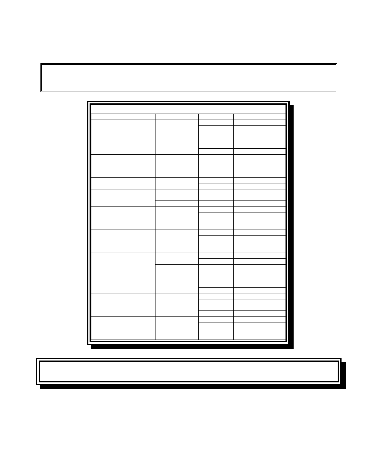
The size of the gas line used for installation is very important. If the line is too small, the gas
pressure at the burner manifold will be low. This may cause slow recovery and delayed ignition.
The incoming gas supply line should be a minimum of 1½” (38 mm) in diameter. Refer to the chart
below for the minimum sizes of connection piping.
Gas Connection Pipe Sizes
(Minimum incoming pipe size should be 1 1/2" (41 mm))
Natural
3/4
" (22 mm)
1" (28 mm) 1 1/4" (36 mm)
Propane 1/2" (15 mm) 3/4" (22 mm) 1" (28 mm)
Manufactured 1" (28 mm) 1 1/4" (36 mm) 1 1/2" (41 mm)
Gas Single Unit 2 - 3 Units
4 or more
units*
* For distances of more than 20 feet (6 m) and/or more
than 4 fittings or elbows, increase the connection by one
pipe size.
2-7
The FilterQuick™ FQG30 Series gas fryer has received the CE mark for the countries and gas
categories indicated in the table below. NOTE: The nominal heat input (QN) is 21kW except for
AT, DE, LU and category 3P/B, which is 23kW.
NOTICE- Australia Only
The air pressure switch on the combustion blower should read: Full Vat units-122pa
(0.5 inches W.C.) and for Split Vat units-180pa (0.72 inches W.C.).
COUNTRIES CATEGORIES GAS PRESSURE (MBAR)
AUSTRIA (AT) II2H3B/P
G20 20
G30, G31 50
BELGIUM (BE)
I2E(R)B G20, G25 20, 25
I3+ G30, G31 28-30, 37
DENMARK (DK) II2H3B/P
G20 20
G30, G31 30
FRANCE (FR)
II2Esi3+
G20, G25 20, 25
G30, G31 28-30, 37
II2Esi3P
G20, G25 20, 25
G31 50
FINLAND (FI) II2H3B/P
G20 20
G30, G31 30
GERMANY (DE)
II2ELL3B/P
G20, G25 20
G30, G31 50
I3P G31 50
GREECE (GR) II2H3+
G20 20
G30, G31 28-30, 37
ITALY (IT) II2H3+
G20 20
G30, G31 28-30, 37
IRELAND (IE) II2H3+
G20 20
G30, G31 28-30, 37
LUXEMBOURG (LU) II2E3B/P
G20 20
G30, G31 50
NETHERLANDS (NL)
II2L3P
G25 25
G31 50
II2L3B/P
G25 25
G30, G31 30
NORWAY (NO) I3B/P G30, G31 30
PORTUGAL (PT) II2H3+
G20 20
G30, G31 28-30, 37
SPAIN (ES)
II2H3+
G20 20
G30, G31 28-30, 37
II2H3P
G20 20
G31 37, 50
SWEDEN (SE) II2H3B/P
G20 20
G30, G31 30
UNITED KINGDOM (UK) II2H3+
G20 20
G30, G31 28-30, 37
CE Standard
Required airflow for the combustion air supply is 2m
3
/h per kW.
1. Connect the quick-disconnect hose to the fryer quick-disconnect under the fryer and to the
building gas line.
NOTE: Some fryers are configured for a rigid connection to the gas supply line. These units
are connected to the gas supply line at the rear of the unit.
CE Approved Gas Categories by Country

2-8
When using thread compound, use very small amounts on male threads only. Use a pipe thread
compound that is not affected by the chemical action of LP gases (Loctite™ PST56765 Sealant
is one such compound). DO NOT apply compound to the first two threads. Doing so may allow
some of the compound to enter the gas stream, resulting in clogging of burner orifices and/or the
control valve.
2. Open the gas supply to the fryer and check all piping, fittings, and gas connections for leaks. A
soap solution should be used for this purpose.
3. Close the fryer drain valve and fill the frypot with water or oil to the bottom OIL LEVEL line at
the rear of the frypot. Light the fryer described in the “Lighting Instructions” topics found in
Chapter 3 of this manual.
DANGER
“Dry-firing” your unit will cause damage to the frypot and can cause a fire. Always
ensure that cooking oil or water is in the frypot before firing your unit.
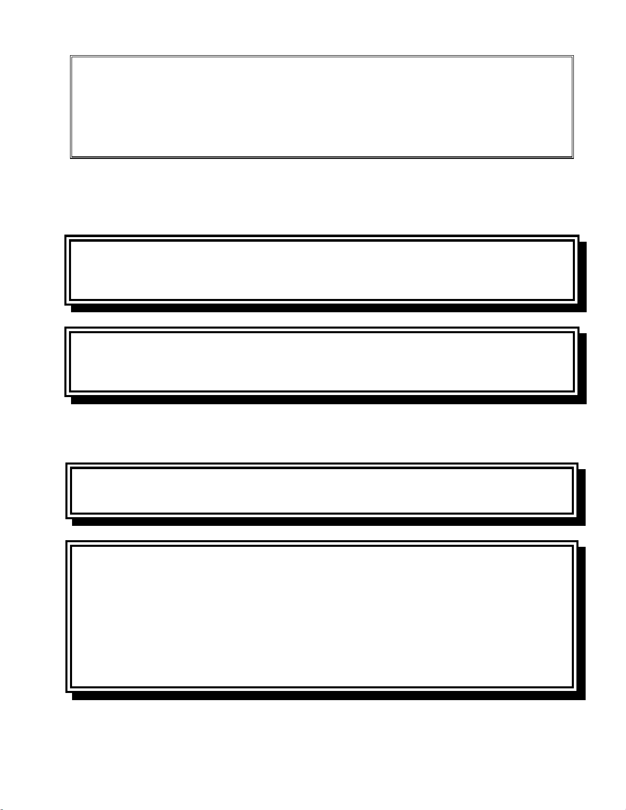
4. The burner manifold pressure should be checked at this time by the local gas company or an
authorized service agent. The tables below and on the following page list the burner manifold
gas pressures for the various gas types that can be used with this equipment.
Natural Gas Lacq
(G20) under 20 mbar
78
Natural Gas Gronique *
(G25) under 25 mbar
10 11.2
Natural Gas Gronique
(G25) under 20 mbar
10 11.2
Butane/Propane
(G30) at 28/30 or 50 mbar
17 17
Propane
(G31) under 37 or 50 mbar
20.6 20.6
* Belgian G25 = 7,0 mbar (single or dual)
Non-CE Standard
Burner Manifold Gas Pressures
Gas Pressure
Natural
3.20" W.C.
0.80 kPa
Propane
8.25" W.C.
2.5 kPa
5. Check the programmed temperature thermostat setting. (Refer to chapter 1 FilterQuick™
Controller Manual) for the setpoint programming instructions for your particular controller.)
2.5 Converting to another Gas Type
DANGER
This appliance was configured at the factory for a specific type of gas. Converting from
one type of gas to another requires the installation of specific gas-conversion compo-
nents. Conversion instructions are included with conversion kits.
2-9
Switching to a different type of gas without installing the proper conversion components
may result in fire or explosion. NEVER ATTACH THIS APPLIANCE TO A GAS SUPPLY
FOR WHICH IT IS NOT CONFIGURED!
Conversion of this appliance from one type of gas to another should only be performed
by qualified, licensed, and authorized installation or service personnel, as defined in
Section 1.7 of this manual.
FilterQuick™ FQG30 series gas fryers manufactured for non-CE countries use different burners for each
type gas. The burners in fryers built for Propane gas have a special gray-colored coating on the burner
tiles to enable them to withstand the higher caloric value of the Propane gas. Burners designed for use in
propane units may be used in natural gas applications, but not vice versa.
Non-CE Gas Conversion Kits
Natural Gas to Propane (LP) Gas Propane (LP) Gas to Natural Gas
Full Vat PN 826-2965 Full Vat PN 826-2967
Dual Vat PN 826-2966 Dual Vat PN 826-2968
Non-CE Gas Conversion Kits for Australia
Natural Gas to Propane (LP) Gas Propane (LP) Gas to Natural Gas
Full Vat PN 826-2969 Full Vat PN 826-2971
Dual Vat PN 826-2970 Dual Vat PN 826-2972
Units manufactured for export to CE countries are equipped with “universal” burners that may be used
with either Natural (G20, G25) gas or Butane (G30) and Propane (G31) gasses.
CE Gas Conversion Kits for Units with Gas Valve 810-1715
G20 or G25 (Natural) to G30 or G31 Gas: G30 or G31 to G20 or G25 (Natural) Gas:
PN 826-2975 PN 826-2976
CE GAS CONVERSION INSTRUCTIONS
1. Between G20- and G25-type Natural Gas, adjust the gas pressure at the regulator. (Refer to the CE
Standard Burner Manifold Gas Pressure Chart.) Do not change the orifice.
2. Between a 2
nd
family (G20 or G25) and a 3
rd
family gas (G30 Butane or G31 Propane):
a. Change the orifices.
b. Adjust the manifold pressure.
3. Remove the old rating plate and return to Frymaster. Affix the new rating plate included with the
conversion kit in place of the old rating plate stating the gas has been converted.
2-10
4. If the destination language changes, replace the rating plate. Call your local service agency or KES
for a label kit. The language of reference will be on the corner of the label.
2.6 Positioning the Fryer
1. Once the fryer has been positioned at the frying station, use a carpenter’s level placed across the
top of the frypot to verify that the unit is level, both side-to-side and front-to-back.
To level fryers, adjust the casters being careful to ensure the fryer(s) are at the proper height in
the frying station.
When the fryer is leveled in its final position, install the restraints provided by the KES to limit
its movement so that it does not depend on or transmit stress to the connection. Install the re-
straints in accordance with the provided instructions. If the restraints are disconnected for service
or other reasons, they must be reconnected before the fryer is used.
DANGER
Hot oil can cause severe burns. Avoid contact. Under all circumstances, oil must be
removed from the fryer before attempting to move it to avoid spills, falls, and severe
burns. Fryers may tip and cause personal injury if not secured in a stationary posi-
tion.
DANGER
Adequate means must be provided to limit the movement of this appliance without
depending on the connector and the quick-disconnect device or its associated pip-
ing to limit the appliance movement.
2. Close fryer drain-valve(s).
2-11
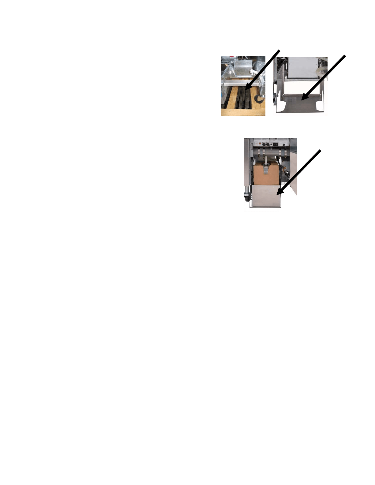
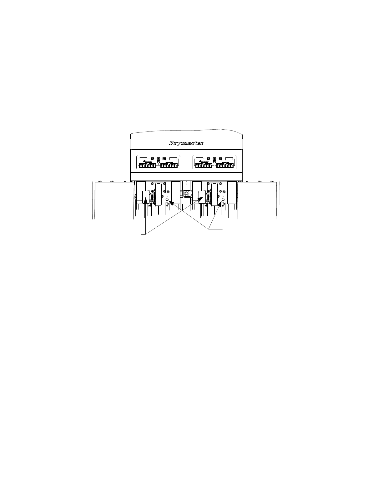
2.7 Installing the JIB Cradle
Open the fryer door (typically the far right door)
and remove the cross brace used for shipping
support by removing the four screws (see Figure
1). Install the JIB cradle shipped in the accesso-
ries pack with the screws that were removed in
the cross brace removal step (see Figure 2). If
using the solid shortening option see Appendix A
in the rear of this manual for installation instruc-
tions. Install the optional JIB splash shield to
protect the bottom of the JIB (see Figure 3).
Figure 1 Figure 2
Figure 3
3-1
FILTERQUICK™ FQG30 SERIES GAS FRYER
CHAPTER 3: OPERATING INSTRUCTIONS
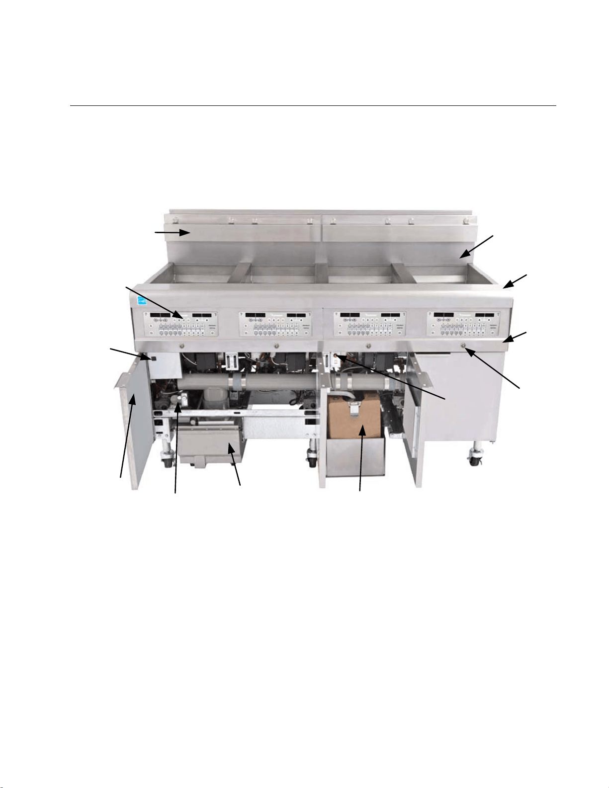
FINDING YOU WAY AROUND THE FILTERQUICK™
FQG30 SERIES GAS FRYER
Flue
Cap
Top Cap
Bezel
JIB (Jug In Box) Oil Reservoir
Control Panel
(FilterQuick
Controller
shown)
Fryer
Identification
Data Labels
(Model and
Serial Number)
Filter Pan
MIB
Board
Drain
Valve
Button
with
LED
Basket
Hanger
Waste
Handle
JIB (Jug
In Box)
Reset
Button
TYPICAL CONFIGURATION (FILTERQUICK FQG430 SHOWN)
NOTE: The appearance of your fryer may differ slightly from that
shown depending upon the configuration and date of manufacture.
3-2
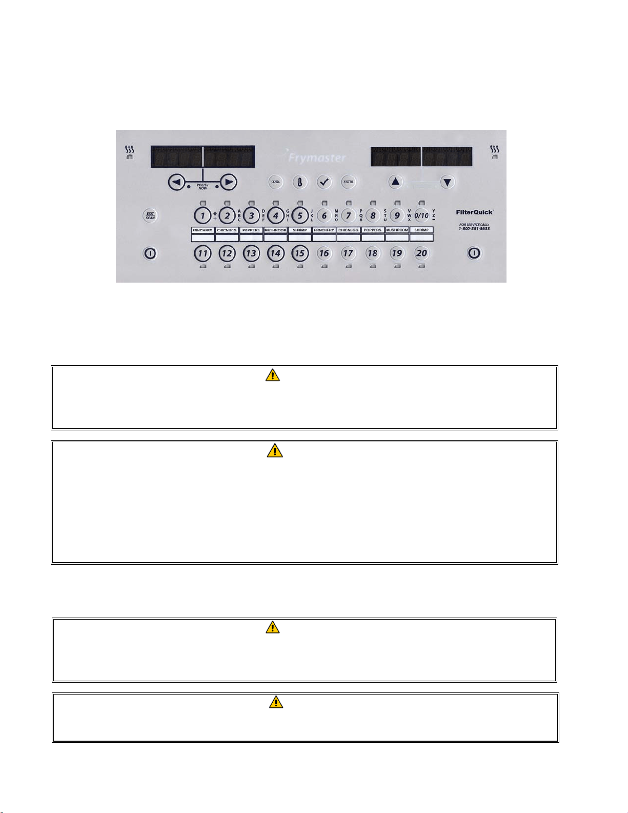
3.1 Controller Operation and Programming
This fryer is equipped with the FilterQuick™ controller (illustrated below). Fryers with FilterQuick™
controllers should refer to the FilterQuick™ Controller Manual 819-7206 for the controller program-
ming and operating procedure.
FILTERQUICK™ CONTROLLER
Refer to Chapter 4 of this manual for operating instructions for the built-in filtration system.
3.2 Equipment Setup and Start-Up Procedures
WARNING
The on-site supervisor is responsible for ensuring that operators are made aware of
the inherent hazards of operating a hot oil filtering system, particularly the aspects
of oil filtration, draining and cleaning procedures.
CAUTION
The cooking oil capacity of the FilterQuick™ FQG30 Series gas fryer is 32 lbs. (3.8
gallons/14.5 liters) at 70°F (21°C) for a full-vat and 18 lbs. (2.2 gallons/8.33 liters) at
70°F (21°C) for each half of a dual-vat.
Before lighting the fryer, make sure the fryer is OFF and the frypot drain valve(s)
is/are closed. Remove the basket support rack(s), if installed, and fill the frypot to
the bottom OIL-LEVEL line.
3.2.1 Setup
WARNING
Never operate this appliance with an empty frypot. The frypot must be filled with wa-
ter or oil before lighting the burners. Failure to do so will damage the frypot and may
cause a fire.
DANGER
Remove all drops of water from the frypot before filling with oil. Failure to do so will
cause spattering of hot liquid when the oil is heated to cooking temperature.
3-3
WARNING
The FilterQuick™ FQG30 Series gas fryer is NOT intended to use solid shortening
without a solid shortening kit. Use only liquid shortening with this fryer if a solid
shortening kit is not installed. The use of solid shortening without a solid
shortening kit will clog the top off oil lines.
1. Fill the frypot with cooking oil to the bottom OIL LEVEL line located on the rear of the frypot.
This will allow for oil expansion as heat is applied. Do not fill cold oil any higher than the bot-
tom line; overflow may occur as heat expands the oil. For bulk oil systems see Section 1.9.8 on
page 1-16 in the FilterQuick™ Controller Manual 819-7206 for instructions to fill the vat from
bulk.
2. Ensure that the power cord(s) are plugged into the appropriate receptacle(s). Verify that the face
of the plug is flush with the outlet plate, with no portion of the prongs visible.
3. Ensure that the oil level is at the top OIL LEVEL line when the oil is at its cooking temperature.
3.2.2 Lighting the Fryer
1. Press the controller ON/OFF switch to the OFF position.
2. Press the controller ON/OFF switch to the ON position and program the controller for normal
cooking temperature.
3. If the burners fail to light, press the ON/OFF switch to the OFF position and wait 60 seconds.
Repeat step 2.
4. The fryer will automatically enter the melt cycle mode if the frypot temperature is below 180ºF
(82ºC). (NOTE: During the melt cycle, the burners will repeatedly fire for a few seconds, then
3-4
go out for a longer period.) When the frypot temperature reaches 180ºF (82ºC), the unit will au-
tomatically switch to the full heat mode. The burners will remain lit until the frypot temperature
reaches the programmed cooking temperature. On the FilterQuick™ controller, once the fryer
reaches setpoint, the controller display changes to READY and the fryer is ready for use. To ex-
it the melt cycle on the FilterQuick™ controller, press the EXIT COOL button. Answer YES to
EXIT MELT? (Note: The fryer will continue the melt cycle for approximately 6 minutes until
the oil level sensor is up to temperature before exiting melt.)
5. After the burners have been lit for at least 90 seconds, observe the flames through the burner
viewing ports located on each side of the combustion air blower.
Right Viewing Ports
Left Viewing Ports are
behind the motor
housings.
The optimum burn is a bright orange-red glow. If a blue flame is observed, or if there are dark spots
on a burner face, adjust the air gas mixture as follows: On the side of the blower housing opposite
the motor is a plate with a locking nut. Loosen the nut enough to allow the plate to be moved, then
adjust the position of the plate to open or close the air intake opening until a bright orange-red glow
is obtained. Carefully hold the plate in position and tighten the locking nut.
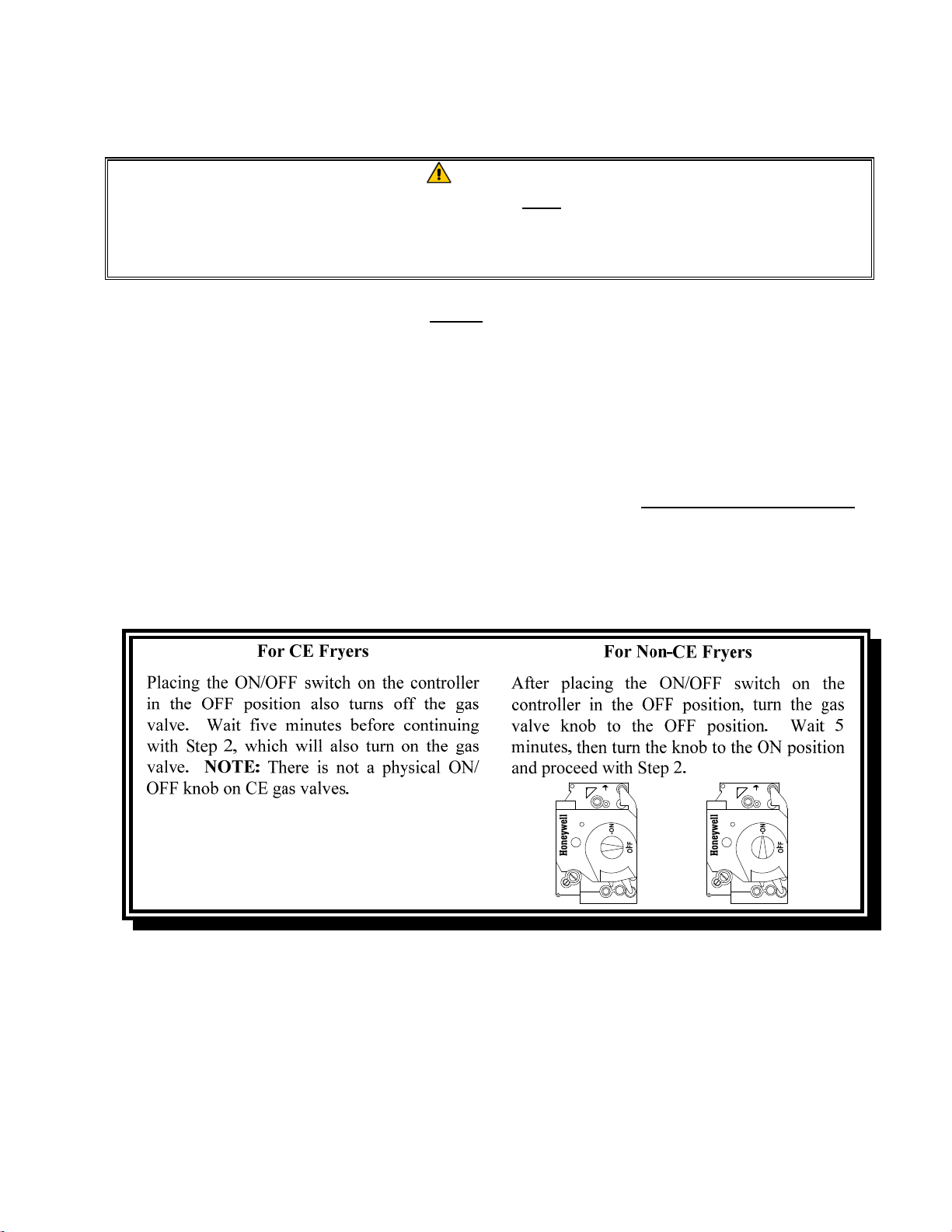
3.3 Shutting the Fryer Down
For short-term shut down during the workday, place the controller ON/OFF switch in the OFF
position and put the frypot covers in place (if the fryer is so equipped).
When shutting the fryers down at closing time, filter the oil and clean the fryers. Place the controller
ON/OFF switch in the OFF position. Then place the gas valve in the off position. See illustration
below.
3-5
Put the frypot covers in place (if the fryer is so equipped).
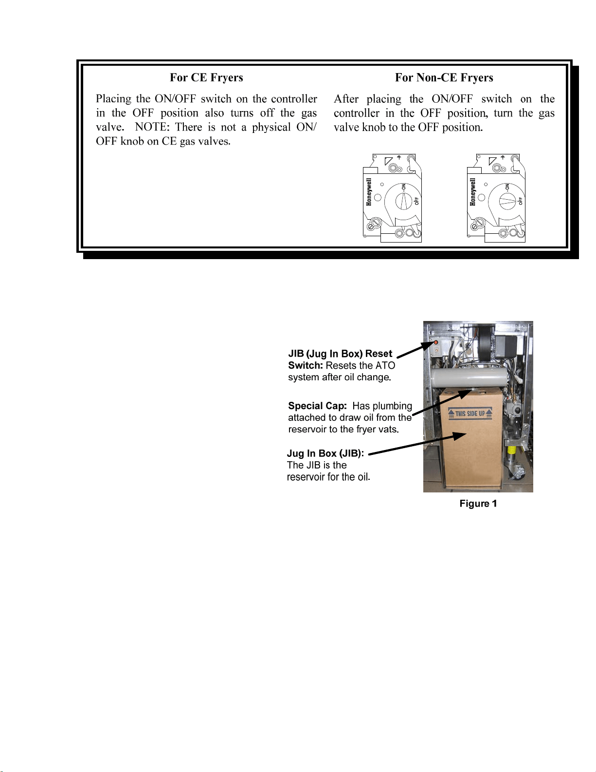
3.4 Oil Attendant
®
Automatic Top-Off
When the Oil Attendant
®
top-off oil sys-
tem is in place on the fryer, oil is continu-
ally topped off in the frypots from a reser-
voir in the cabinet. The reservoir holds up
to a 35 pound box of oil. In a typical op-
eration this will last approximately two
days before changing. Components of the
system are annotated at the right (see Fig-
ure 1).
NOTE: The system is intended to top
off the frypots from the oil reservoir, not
fill the vats from the reservoir. The fry-
pots will require manual filling upon
startup and after disposal unless a bulk
fresh oil system is used.
3.4.1 Install the Oil Reservoir
Remove the original lid from the oil container and foil liner. Replace with the provided cap, which
has connected suction hardware. Ensure the feeder tube from the cap reaches to the bottom of the oil
container.
Place the oil container inside the cabinet and slide it into place (as shown on the following page).
Avoid catching the suction hardware on the cabinet interior as the container is placed in the fryer.
The system is now ready for operation. As the fryer heats to preprogrammed temperatures, the sys-
tem will energize and then slowly add oil to the frypot as needed, until the oil reaches an optimal
level.
3-6
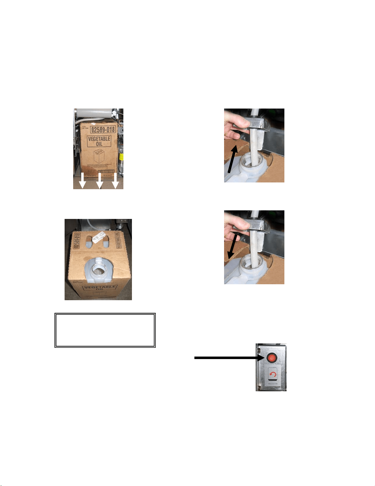
3.4.2 Routine Oil Changes
When the oil reservoir level is low, the controller displays TOPOFF OIL EMPTY in the left display
and CONFIRM in the right display. Press (CONFIRM). Some procedures may differ from photos
shown. If using solid shortening see Appendix C for instructions. Follow manufacturer’s instructions
for changing the JIB.
1. Open the cabinet and slide the JIB from
the cabinet (see Figure 2).
Figure 2
2. Remove the cap and pour any remaining oil in the
container into all fry vats equally (see Figure 3).
Figure 3
3. With the jug upright remove the cap and
foil seal (see Figure 4).
Figure 4
4. Put the tube in the new full container (see Figure 5).
Figure 5
5. Slide the JIB onto the shelf inside the fryer cabinet
(as seen in Figure 2).
6. Press and hold the orange JIB reset switch ten (10)
seconds to reset the top off system. (see Figure 6).
3.4.3 Bulk Oil Systems
Instructions for installing and using bulk oil systems are found in Appendix A locat-
ed at the rear of this manual.
WARNING: Do not add
HOT or USED oil to a JIB.
Figure 6
Image and location may differ
from photo.
4-1
FILTERQUICK™ FQG30 SERIES GAS FRYERS
CHAPTER 4: FILTRATION INSTRUCTIONS
4.1 Introduction
The FilterQuick
™
with fingertip filtration system allows the oil in one frypot to be safely and
efficiently filtered while the other frypots in a battery remain in operation.
Section 4.2 covers preparation of the filter system for use. Operation of the system is covered in
Section 4.3.
WARNING
The on-site supervisor is responsible for ensuring that operators are made aware of
the inherent hazards of operating a hot oil filtering system, particularly the aspects
of oil filtration, draining and cleaning procedures.
WARNING
The filter pad or paper MUST be replaced daily or when the sediment level exceeds
the height of the hold down ring.
4.2 Preparing the FilterQuick™ with Fingertip Filtration System for Use with Filter
Paper or Filter Pad
The FilterQuick™ with fingertip filtration system allows the oil in one frypot to be safely and
efficiently filtered while the other frypots in a battery remain in operation. The FilterQuick™
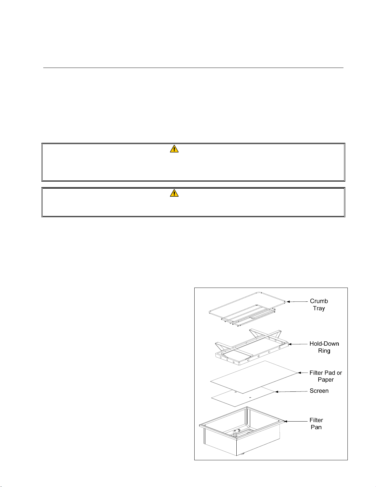
filtration system uses a filter paper configuration which includes a crumb tray, large hold-down ring,
and metal filter screen.
1. Pull the filter pan out from the cabinet and
remove the crumb tray, hold-down ring, filter
paper and filter screen (see Figure1). Clean
all components with a solution of detergent
and hot water then dry thoroughly.
The pan cover must not be removed except
for cleaning, interior access, or to allow a
shortening disposal unit (SDU) built before
January 2004 to be positioned under the
drain. Disposal instructions are on page 1-13
in the controller manual 819-7206.
Figure 1
4-2
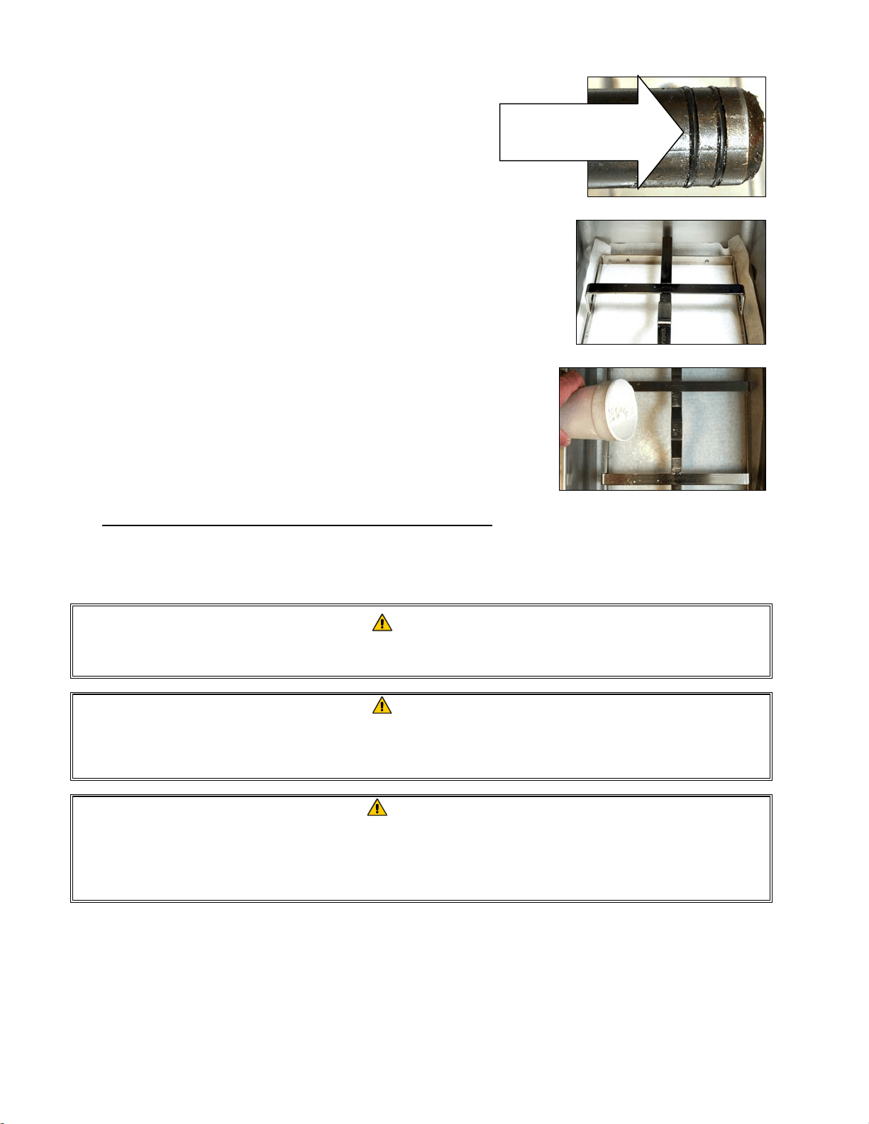
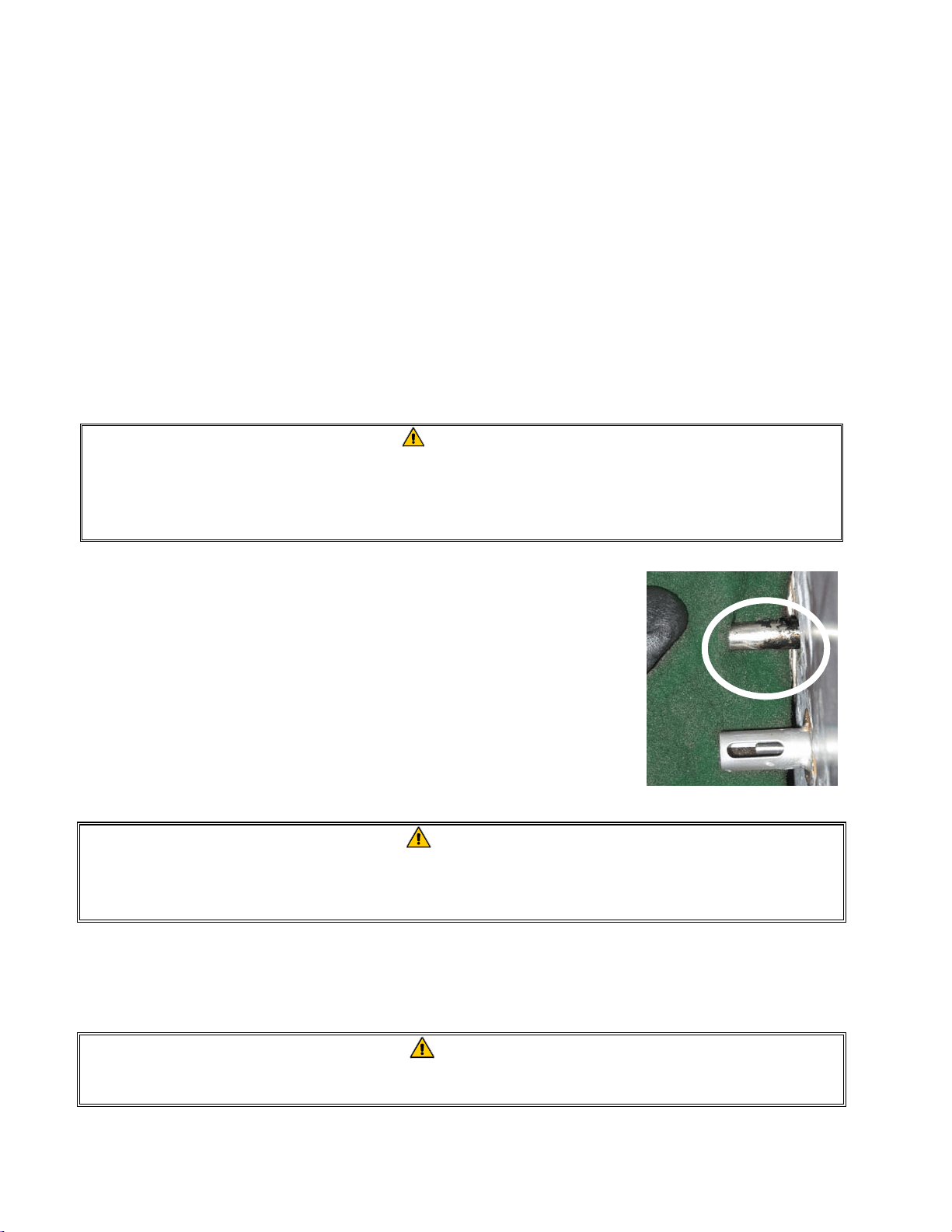
2. Inspect the filter pan connection fitting to ensure that
both O-rings are in good condition (see Figure 2).
3. Then in reverse order, place the metal filter screen in
the center of the bottom of the pan, then lay a sheet of
filter paper on top of the screen, overlapping on all
sides (see Figure1). If using a filter pad, ensure the
rough side of the pad is up and lay the pad over the
screen, making sure that the pad is in between the
embossed ridges of the filter pan.
4. Position the hold-down ring over the filter paper and
lower the ring into the pan, allowing the paper to rest
on the sides of the filter pan (see Figure 3).
5. When the hold-down ring is in position, if using filter
paper, sprinkle one packet of filter powder evenly
over the paper. (See Figure 4)
6. Replace the crumb tray in the filter pan, then push the
filter pan back into the fryer, positioning it under the
drain.
Figure 2
Figure 3
Figure 4
DO NOT USE FILTER POWDER WITH THE PAD!
7. Push the filter pan back into the fryer, positioning it under the fryer. Ensure “A” is displayed on
the MIB board. The filtration system is now ready for use.
DANGER
Do not drain more than one frypot at a time into the built-in filtration unit to avoid
overflow and spillage of hot oil that may cause severe burns, slipping and falling.
DANGER
The crumb tray in fryers equipped with a filter system must be emptied into a
fireproof container at the end of frying operations each day. Some food particles can
spontaneously combust if left soaking in certain shortening material.
WARNING
Do not bang fry baskets or other utensils on the fryer’s joiner strip. The strip is
present to seal the joint between the fry vessels. Banging fry baskets on the strip to
dislodge shortening will distort the strip, adversely affecting its fit. It is designed for
a tight fit and should only be removed for cleaning.
4.3 FilterQuick™ with Fingertip Filtration
The FilterQuick™ controller has a feature that will prompt the operator to begin the semi-automatic
filtration process, after a number of preset cook cycles.
Inspect the filter
connection fitting
O-rings.

4-3
A FilterQuick™ controller controls the semi-automatic filtration system on the FilterQuick™ fryer.
After a preset number of cook cycles the controller displays Filter now? alternating with
YES NO. If NO is selected or a cook cycle is started, the controller will resume normal
operation for a set amount of cooks and the prompt for a filter again. The FILTER NOW? prompt is
displayed once the cooks til filter or filter prompt count is satisfied. Refer to page 1-12 of the
FilterQuick™ controller manual 819-7206 for filter steps. All messages need to be confirmed or
cleared on all controllers prior to starting any filtration process.
4.4 Troubleshooting the FilterQuick
™
with Fingertip Filtration
4.4.1 Incomplete Filtration
Should the filter procedure fail after the filter paper or pad was changed an error message is
generated.
The controller displays IS VAT FULL? alternating with yes no.
The MIB board displays three horizontal lines.
1. If the vat is full press the (YES) button to continue. The controller
returns to idle cook mode or OFF.
If the pot is not filled completely continue to next step.
2. Press (NO) if pot is not filled completely.
The controller displays FILLING while the pump runs again. When the pump stops, the controller
displays IS VAT FULL? alternating with yes no again. If the vat is full go to step 1. If the
vat is not completely filled continue.
3. Press (NO) if pot is not filled completely.
The controller displays FILLING while the pump runs again. When the pump stops, the controller
displays IS VAT FULL? alternating with yes no again. If the vat is full go to step 1. If the
vat is not completely filled continue.
4. Press (NO) if pot is not filled completely. If this is the sixth
consecutive sequence of incomplete filtration skip to step 8.
The controller displays CHANGE FILTER PAPER? alternating with YES NO and an
alarm.
5. Press (YES) to continue.
Pressing (NO) allows the fryer to return to cook mode in most cases for
four minutes or 15 minutes if the paper is expired*, ending with the
CHANGE FILTER PAPER? alternating with YES NO display.
This repeats until YES is chosen.

4-4
The controller displays REMOVE PAN.
*NOTE: If the filter paper change time has expired, normally every 25
hours, the CHANGE FILTER PAPER? message repeats every 15
minutes instead of every four minutes.
6. Remove the pan. The controller display changes to CHANGE PAPER. Change the filter
paper and ensure the filter pan has been pulled forward, out of the cabinet for at least 30 seconds.
Once the pan has been out for 30 seconds the controller displays OFF. Ensure the pan is dry
and assembled correctly. Push the filter pan back into the fryer. Ensure “A” is displayed on the
MIB board.
7. Switch the controller on. The controller displays the fryer temperature until the fryer reaches
setpoint.
8. If a filtration error occurs six consecutive times, the return valve closes and the controller
displays SERVICE REQUIRED alternating with YES and an alarm.
9. Press (YES) to silence alarm and continue.
The controller displays SYSTEM ERROR and the error message for 15
seconds changing to SYSTEM ERROR FIXED alternating with YES
NO.
10. Press (NO) to continue cooking. Call your FAS to repair and reset
the fryer. The error will be re-displayed every 15 minutes until the issue
is repaired. Semi-automatic filtration and auto top off is disabled until
the fryer is reset.
4.4.2 Clogged Drain Error
The clogged drain error occurs during auto filtration when the oil level sensor detects that oil has not
completely drained from the frypot. This may be due to a clogged drain or an oil sensor failure.
When this occurs the controller displays CLEAR DRAIN for 15 seconds changing to IS
DRAIN CLEAR? alternating with YES.
1. Clear debris from the drain using the fryer’s friend and press the (YES) button to continue.
2. The controller displays DRAINING. Once the oil level sensor detects the oil has drained,
normal auto filtration operation resumes.
4.5 Filter Busy
When FILTER BUSY is displayed on the controller, the system is waiting on another vat to be
filtered or waiting on another issue to clear. Wait 15 minutes to see if problem is corrected. If not,
call your local FAS.
4-5
DANGER
Do not drain more than one frypot at a time into the built-in filtration unit to avoid
overflow and spillage of hot oil that may cause severe burns, slipping and falling.
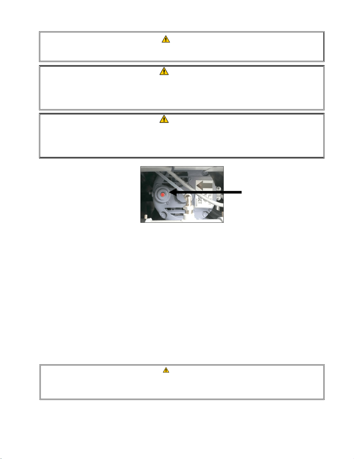
WARNING
The filter pump is equipped with a manual reset switch in case the filter motor
overheats or an electrical fault occurs. If this switch trips, turn off power to the filter
system and allow the pump motor to cool 20 minutes before attempting to reset the
switch (see photo below).
WARNING
Use caution and wear appropriate safety equipment when resetting the filter pump
reset switch. Resetting the switch must be accomplished with care to avoid the
possibility of a serious burn from careless maneuvering around the drain tube and
frypot.
Filter Pump Reset Switch
4.6 Draining and Refilling Vats, and Disposing of Oil
When cooking oil requires changing, drain the oil into an appropriate container for transport to the
disposal container. (For safe, convenient draining and disposal of used oil, Frymaster recommends
the use of the Frymaster Shortening Disposal Unit (SDU) for JIB systems. The SDU is available
through your local distributor.) Do not drain boil-out solution into an SDU. NOTE: If using
an SDU built before January 2004 the filter pan cover must be removed to allow the unit to be
positioned beneath the drain. To remove the cover, lift up on the front edge slightly and slip the oil
guard up and pull it straight out of the cabinet. Refer to the documentation furnished with your
disposal unit for specific operating instructions. If a shortening disposal unit is not available, allow
the oil to cool to 100°F (38°C), then drain the oil into a METAL container with a capacity of FOUR
(4) gallons (15 liters) or larger to prevent oil from spilling. If using a bulk oil system, follow the
disposal and refilling instructions for bulk oil in the FilterQuick Controller Manual 819-7206.
DANGER
When draining oil into an appropriate METAL container, make sure the container will
hold at least FOUR gallons (15 liters) or more, otherwise hot liquid could overflow
and cause injury.
4-6
DANGER
Allow oil to cool to 100°F (38°C) before draining into an appropriate METAL
container for disposal.
DANGER
When draining oil into a disposal unit, do not fill above the maximum fill line located
on the container.
DANGER
Draining and filtering of cooking oil must be accomplished with care to avoid the
possibility of a serious burn caused by careless handling. The oil to be filtered is at
or near 350°F (177°C). Wear all appropriate safety equipment when draining and
filtering oil.
WARNING
NEVER drain boil-out solution into an SDU. Boil-out solution can cause damage to
an SDU.
1. Turn the controller power switch to the OFF position.
2. Remove the filter pan and position the SDU or METAL container with a sealable cover with a
capacity of FOUR gallons (15 liters) or larger under the fryer drainpipe to drain the oil. The
METAL container must be able to withstand the heat of the oil and hold hot liquids.
3. Follow the instructions for disposing of oil on page 1-13 thru 1-14 of the FilterQuick
™
controller
manual for disposal or draining steps. If the drain valve becomes clogged with food particles,
use the Fryer’s Friend (poker-like tool) to clear the blockage.
DANGER
DO NOT hammer on the drain valve with the cleanout rod or other objects. Damage
to the ball inside will result in leaks and will void the Frymaster warranty.
4. After draining the oil, clean all food particles and residual oil from the frypot. BE CAREFUL,
this material may still cause severe burns if it comes in contact with bare skin.
5. Once the drain valve is closed, fill the frypot with clean, filtered or fresh cooking oil to the
bottom OIL-LEVEL line.
5-1
FILTERQUICK™ FQG30 GAS FRYER
CHAPTER 5: PREVENTATIVE MAINTENANCE
5.1 Fryer Preventive Maintenance Checks and Service
DANGER
The crumb tray in fryers equipped with a filter system must be emptied into a fireproof con-
tainer at the end of frying operations each day. Some food particles can spontaneously
combust if left soaking in certain shortening material.
DANGER
Never attempt to clean the fryer during the frying process or when the frypot is filled with hot
oil. If water comes in contact with oil heated to frying temperature, it will cause spattering of
the oil, which can result in severe burns to nearby personnel.
WARNING
Use a multi-purpose detergent. Read the directions for use and precautionary statements
before use. Particular attention must be paid to the concentration of cleaner and the length
of time the cleaner remains on the food-contact surfaces.
5.2 DAILY CHECKS AND SERVICE
5.2.1 Inspect Fryer and Accessories for Damage
Look for loose or frayed wires and cords, leaks, foreign material in frypot or inside cabinet, and any other indica-
tions that the fryer and accessories are not ready and safe for operation.
5.2.2 Clean Fryer Cabinet Inside and Out - Daily
Clean inside the fryer cabinet with dry, clean cloth. Wipe all accessible metal surfaces and components to remove
accumulations of oil and dust.
Clean the outside of the fryer cabinet with a clean, damp cloth soaked with degreaser, removing oil, dust, and lint
from the fryer cabinet. Wipe with a clean, damp cloth.
5.2.3 Clean the FilterQuick
™
Filtration System - Daily
WARNING
Never operate the filter system without oil in the system.
WARNING
Never use the filter pan to transport old oil to the disposal area.
WARNING
Never drain water into the filter pan. Water will damage the filter pump.
5-2
There are no periodic preventive maintenance checks and services required for your FilterQuick Filtration System
other than daily cleaning of the filter pan with a solution of hot water and detergent.
If you notice that the systems is pumping slowly or not at all, verify that the filter pan screen is on the bottom of
the filter pan, with the pad on top of the screen. Verify that the two O-ring(s) on the fitting at the right front of the
filter pan are present and in good condition.
5.2.4 Clean Filter Pan, Detachable Parts and Accessories
Carbonized oil will accumulate on the filter pan and detachable parts and accessories such as baskets, sediment
trays, or fish plates.
Wipe the filter pan and all detachable parts and accessories with a clean cloth dampened with a detergent solution
(or the parts can be run through a dishwasher). Rinse and thoroughly dry each part. DO NOT use steel wool or
abrasive pads to clean these parts. The scratches that result from such scrubbing make subsequent cleanings more
difficult.
WARNING
Use a commercial-grade cleaner formulated to effectively clean and sanitize food
contact surfaces. Read the directions for use and precautionary statements before
use. Particular attention must be paid to the concentration of cleaner and the
length of time the cleaner remains on the food-contact surfaces.
5.2.5 Clean Oil Level Sensor
1. Drain the oil using the drain to pan option in the filter menu.
2. Use a no-scratch pad to clean carbonized oil off of the sensor (see photo
right).
3. Return the oil using the fill vat from pan option in the filter menu.
5.3 WEEKLY CHECKS AND SERVICE
5.3.1 Drain and Clean Frypot
DANGER
Never operate the appliance with an empty frypot. The frypot must be filled with
water or oil before lighting the burners. Failure to do so will damage the frypot and
may cause a fire.
After the fryer has been in use for a period of time, a hard film of caramelized oil will form on the inside of the
frypot. This deposit must be periodically removed to maintain your fryer’s efficiency.
See the Clean and Filter procedure instructions on page 1-12 in the FilterQuick
™
controller manual to clean the
frypot.
DANGER
Allow oil to cool to 100ºF (38ºC) or lower before draining to an appropriate container for
disposal.
5-3
5.3.2 Boiling Out the Frypot
During normal usage of your fryer, a deposit of carbonized oil will gradually form on the inside of the frypot. This
film should be periodically removed by following the boil-out procedure. Use the instructions on pages 1-16
through 1-18 in the FilterQuick
™
controller manual to boil out the frypot.
WARNING
To prevent injury, ensure adjacent vats that contain oil are OFF and covered prior to
performing a boil out.
To boil out all frypots simultaneously dispose of all the oil using the instructions on page 1-13 through 1-14 in the
FilterQuick
™
controller manual. Once the oil is disposed follow the procedures below:
1. Program a product button for 195°F and follow the instructions on the detergent container.
2. When the solution is finished simmering, turn off controller.
3. Remove the filter pan and position a METAL container with a sealable cover with a capacity of FOUR
gallons (15 liters) or larger under the fryer drainpipe to drain the boil out solution. The METAL container
must be able to withstand the heat of the hot liquids.
4. Drain out the solution using the drain to pan instructions on page 1-15 in the FilterQuick
™
controller man-
ual and clean the frypot(s) thoroughly.
WARNING
Never leave the fryer unattended during this process. If the solution overflows, press the
ON/OFF switch to the OFF position immediately.
WARNING
NEVER drain boil-out solution into a shortening disposal unit (SDU), a built-in filtration unit,
or a portable filter unit. These units are not intended for this purpose, and will be damaged
by the solution.
DANGER
When draining hot boil-out solution into an appropriate METAL container, make sure the
container will hold at least FOUR gallons (15 liters) or more, otherwise hot liquid could over-
flow and cause injury.
5. Refill the frypot(s) with clean water. Rinse the frypot(s) twice, drain and dry with a clean towel. Thor-
oughly remove all water from the frypot before refilling the frypot with oil to the bottom OIL-LEVEL line.
DANGER
Ensure that the frypot is completely free of water before filling with oil. When the oil is
heated to cooking temperature, water in the frypot will cause splattering.
5.4 MONTHLY CHECKS AND SERVICE
5.4.1 Check FilterQuick™ Controller Set Point Accuracy
1. Insert a good-grade thermometer or pyrometer probe into the oil, with the end touching the fryer temperature-
sensing probe.
5-4
2. When the controller displays READY (indicating that the frypot contents are within the cooking range), press
the temperature button once to display the temperature of the oil as sensed by the temperature probe and the
setpoint. The setpoint is denoted by the temperature with the degree symbol.
3. Note the temperature on the thermometer or pyrometer. Actual temperature and pyrometer readings should be
within ± 5ºF (3ºC) of each other. If not, contact a Factory Authorized Servicer for assistance.
5.5 QUARTERLY CHECKS AND SERVICE
5.5.1 REPLACE THE O-RINGS
Refer to page 4-2 for inspection of O-rings.
5.6 SEMI-ANNUAL CHECKS AND SERVICE
5.6.1 Clean Gas Valve Vent Tube
NOTE: This procedure is not required for fryers configured for export to CE countries.
1. Set the fryer power switch and the gas valve to the OFF position.
2. Carefully unscrew the vent tube from the gas valve. NOTE: The vent tube may be straightened for ease in
removal.
3. Pass a piece of ordinary binding wire through the tube to remove any obstruction.
4. Remove the wire and blow through the tube to ensure it is clear.
5. Reinstall the tube and bend it so that the opening is pointing downward
.
5.6.2 Check Burner Manifold Pressure
DANGER
This task should be performed by qualified service personnel only. Contact your
FAS to arrange this service.
5.7 ANNUAL/PERIODIC SYSTEM INSPECTION
This appliance should be inspected and adjusted periodically by qualified service personnel as part of a reg-
ular kitchen maintenance program.
Frymaster recommends that a Factory Authorized Servicer inspect this appliance at least annually as fol-
lows:
5.7.1 Fryer
Inspect the cabinet inside and out, front and rear for excess oil.
Verify that debris or accumulations of solidified oil do not obstruct the flue opening.

5-5
Verify that burners and associated components (i.e. gas valves, pilot assemblies, ignitors, etc.) are in good
condition and functioning properly. Inspect all gas connections for leaks and verify that all connections are
properly tightened.
Verify that the burner manifold pressure is in accordance with that specified on the appliance’s rating plate.
Verify that the temperature and high-limit probes are properly connected, tightened and functioning properly,
and that probe guards are present and properly installed.
Verify that component box components (i.e. controller, transformers, relays, interface boards, etc.) are in good
condition and free from oil and other debris. Inspect the component box wiring and verify that connections
are tight and that wiring is in good condition.
Verify that all safety features (i.e. reset switches, etc.) are present and functioning properly.
Verify that the frypot is in good condition and free of leaks and that the frypot insulation is in serviceable con-
dition.
Verify that wiring harnesses and connections are tight and in good condition.
5.7.2 FilterQuick™ Filtration System
Inspect all oil-return and drain lines for leaks and verify that all connections are tight.
Inspect the filter pan for leaks and cleanliness. If there is a large accumulation of crumbs in the crumb basket,
advise the owner/operator that the crumb basket should be emptied into a fireproof container and cleaned dai-
ly.
Verify that all O-rings and seals are present and in good condition. Replace O-rings and seals if worn or dam-
aged.
Check filtration system integrity as follows:
Verify that filter pan cover is present and properly installed.
With the filter pan empty, place each vat into fill vat from pan selection (see page 1-15 of the Filter-
Quick
™
controller manual), one at a time. Verify proper functioning of each oil return valve by activating
the filter pump using the fill vat from pan selection. Verify that the pump activates and that bubbles ap-
pear in the cooking oil of the associated frypot only.
Verify that the filter pan is properly prepared for filtering, then drain a frypot of oil heated to a setpoint
above 300°F (149°C) (into the filter pan by using the drain to pan selection (see page 1-15 of the Filter-
Quick™ Controller Manual). Now using the fill vat from pan drain pan selection (page 1-15 of the
FilterQuick™ Controller Manual), allow all oil to return to the frypot (indicated by bubbles in the cooking
oil). Press the up arrow button when all oil is returned. The frypot should have refilled in approximately 2
minutes and 30 seconds.

5-6
5.7.3 Clean Combustion Air Blower Assembly
1. Disconnect the blower wiring harness and remove the four blower mounting nuts.
(See Figure 1 on below)
Figure 1
2. Remove the three fasteners that secure the blower motor assembly to the blower housing, and separate the two
components. (See Figure 2)
Figure 2
3. Wrap the motor with plastic wrap to prevent water from entering it. Spray degreaser or detergent on the
blower wheel and the blower housing. Allow it to soak for five minutes. Rinse the wheel and housing with
hot tap water, then dry with a clean cloth. (See Figure 3)
Blower Housing
Blower Wheel
Wrap the motor and wires
with plastic wrap or a
plastic bag.
Figure 3
4. Remove the plastic wrap from the blower motor assembly. Reassemble the blower motor assembly and
blower housing. Reinstall the blower assembly in the fryer.
5. Reinstall the blower shield or shield assembly.
6. Light the fryer in accordance with the procedure described in Chapter 3, Section 3.2.2.
Wiring connection
Blower
assembly
mounting nuts
Remove these fasteners.
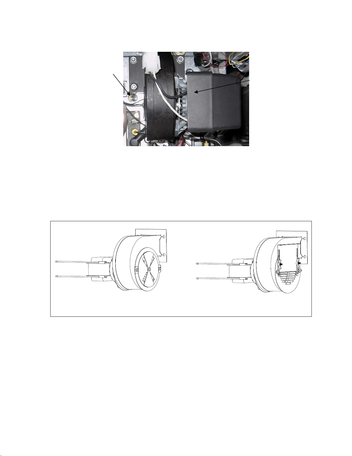
5-7
7. After the burners have been lit for at least 90 seconds, observe the flames through the burner viewing ports
located on each side of the combustion air blower. (See Figure 4)
Figure 4
The air/gas mixture is properly adjusted when the burner manifold pressure is in accordance with the applicable
table on page 2-7 and the burners display a bright orange-red glow. If a blue flame is observed, or if there are dark
spots on a burner face, the air/gas mixture requires adjustment.
On the side of the blower housing opposite the motor is a plate with one or two locking nuts (see illustration on the
following page). Loosen the nut(s) enough to allow the plate to be moved, then adjust the position of the plate to
open or close the air intake opening until a bright orange-red glow is obtained. Carefully hold the plate in position
and tighten the locking nut(s).
TYPICAL BLOWER ASSEMBLY
SOME CE BLOWER ASSEMBLIES
MAY BE CONFIGURED THIS WAY
Right
Viewing
Port is
Behind
Motor
Left Viewing
Port
6-1
FILTERQUICK™ FQG30 SERIES GAS FRYERS
CHAPTER 6: OPERATOR TROUBLESHOOTING
6.1 Introduction
This chapter provides an easy reference guide to some of the common problems that may occur
during the operation of your equipment. The troubleshooting guides that follow are intended to help
you correct, or at least accurately diagnose, problems with your equipment. Although the chapter
covers the most common problems reported, you may encounter problems that are not covered. In
such instances, the Frymaster Technical Services staff will make every effort to help you identify
and resolve the problem.
When troubleshooting a problem, always use a process of elimination starting with the simplest
solution and working through to the most complex. Most importantly, always try to establish a clear
idea of why a problem has occurred. Part of your corrective action involves taking steps to ensure
that it doesn’t happen again. If a controller malfunctions because of a poor connection, check all
other connections while you’re at it. If a fuse continues to blow, find out why. Always keep in mind
that failure of a small component may often be indicative of potential failure or incorrect functioning
of a more important component or system.
If you are in doubt as to the proper action to take, do not hesitate to call the Frymaster Technical
Service Department or your local Frymaster Factory Authorized Servicer for assistance.
Before calling a servicer or the Frymaster HOTLINE (1-800-551-8633):
Verify that electrical cords are plugged in and that circuit breakers are on.
Verify that gas line quick-disconnects are properly connected.
Verify that any gas line cutoff valves are open.
Verify that frypot drain valves are fully closed.
Have your fryer’s model and serial numbers ready to give to the technician assisting
you.
DANGER
Hot oil will cause severe burns. Never attempt to move this appliance when filled
with hot cooking oil or to transfer hot cooking oil from one container to another.
DANGER
This equipment should be unplugged when servicing, except when electrical circuit
tests are required. Use extreme care when performing such tests.
This appliance may have more than one electrical power supply connection point.
Disconnect all power cords before servicing.
Inspection, testing, and repair of electrical components should be performed by an
authorized service agent only.

6-2
6.2 Troubleshooting Fryers
6.2.1 Controller and Heating Problems
PROBLEM PROBABLE CAUSES CORRECTIVE ACTION
No displa
y
on the
controller.
A. Controller not turned on.
B. No power to fryer.
C. Failed controller or other
component
A. Press the ON/OFF switch to turn the controller
on.
B. Verify that the fryer is plugged in and that the
circuit breaker is not tripped.
C. Call your FAS for assistance.
Controller displays
IS VAT FULL?
YES NO during a
cook or in idle mode
with an audible
alarm.
A. An error has occurred due to
carbon buildup on oil level sensor.
B. CAN communication issues,
component failure issues.
A. If answering yes directs to IS OIL SENSOR
CLEAN? CONFIRM, clean the oil level
sensor with a scratch pad and power cycle the
controller.
B. If the issue persists contact your FAS for
assistance.
Controller displays
IS OIL SENSOR
CLEAM?
CONFIRM during a
cook or in idle mode
with an audible
alarm.
A. The oil level sensor may be
coated with caramelized oil.
B. CAN communication issues,
component failure issues.
A. Clean sensor with scratch pad.
B. If the issue persists contact your FAS for
assistance.
Controller displays
CHANGE FILTER
PAPER?
Daily filter paper change prompt has
occurred.
Press (YES), follow prompts and change the
filter paper.
Fryer repeatedly cycles
on and off when first
started.
Fryer is in melt cycle.
This is normal operation. This will continue until
the fryer temperature reaches 180ºF (82ºC).
Fryer does not heat.
A. Drain valve not fully closed.
B. Gas valve is not turned on.
C. Manual gas shut off valve closed.
D. Improperly connected quick-
disconnect fitting on gas line.
E. Obstructed or failed combustion air
blower.
A. Check status of MIB – Ensure A is displayed.
B. Turn the gas valve knob to the ON position.
C. Verify that any in-line manual shut off and gas
main valve is open.
D. Verify that the quick-disconnect fitting on
the flexible gas line is firmly connected to the
fryer.
E. Verify that combustion air blower is running.
If not, call your FAS for service. If
combustion air blower is functional, clean and
adjust per instructions in Chapter 5 of this
manual.
Fryer is operating
normally, but recovery
is slow when cooking.
Dirty or obstructed combustion air
blower.
Clean and adjust per instructions in Chapter 5 of
this manual.
Heat indicator is on and
blower is running, but
burner will not ignite.
Blown fuse on interface board or
ignition module.
Contact your FAS for service.
Fryer is operating
normally, but produces
a popping sound when
burners ignite.
A. Dirty or obstructed combustion
air blower.
B. Dirty or obstructed gas valve vent
tube (non-CE fryers only).
C. Malfunctioning combustion air
A. Clean and adjust per instructions in Chapter 5
of this manual.
B. Clean per instructions in Chapter 5 of this
manual.
C. If blower is slow to come up to speed, contact
6-3
PROBLEM PROBABLE CAUSES CORRECTIVE ACTION
blower. your FAS for service.
Controller displays
HEATING
FAILURE.
Gas valve off, failed controller,
failed transformer, open high-limit
thermostat.
It is normal for this message to appear during
startup if the lines have air in them. Check that
the gas valve is on. If it continues, shut the fryer
down and call your FAS for assistance.
6.2.2 Error Messages and Display Problems
PROBLEM PROBABLE CAUSES CORRECTIVE ACTION
Controller displays
low temp.
Frypot temperature has dropped
more than 30°F (17°C) lower than
setpoint in idle mode or 45°F (25°C)
in cook mode.
This display is normal for a short while if a large
batch of frozen product is added to the frypot or if
the fryer is not heating properly. If the issue
persists call your FAS for assistance.
Controller displays
Hot hi-1.
Frypot temperature is more than
410ºF (210ºC) or, in CE countries,
395ºF (202ºC).
Shut the fryer down immediately and call your
FAS for assistance.
Controller displays Hi
temp.
Frypot temperature is more than 40
ºF (4ºC).
Press the power button to turn off fryer and let
cool before returning power to fryer. If issue
continues call your FAS for assistance.
Controller displays
RECOVERY
FAULT/ YES and
alarm sounds.
Recovery time exceeded maximum
time limit.
Clear error and silence the alarm by pressing the
(YES) button. Maximum recovery time is 2:25. If
the error continues call your FAS for assistance.
Controller display is in
wrong temperature scale
(Fahrenheit or Celsius).
Incorrect display option
programmed.
Fryers using the FilterQuick
™
controller can toggle
between F° to C° by pressing the button until
Product setup is displayed. Press to scroll to
Tech Mode and press . Enter 1658. Press the
scan button. The controller displays OFF. Turn
the controller on to check temperature. If the
desired scale is not displayed, repeat.
Controller displays
High limit
failure
disconnect
power.
A. Open drain valve
B. Failed high limit
A. Close the drain valve.
B. Shut the fryer down immediately and call your
FAS for assistance.
Controller displays
TEMP PROBE
FAILURE
Problem with the temperature
measuring circuitry including the
probe or damaged controller wiring
harness or connector.
Shut the fryer down and call your FAS for
assistance.
Controller displays
SERVICE
REQUIRED followed
by an error message.
An error has occurred which
requires a service technician.
Press the (YES) button if the issue is fixed or
press the (NO) button to continue cooking and
call your FAS for assistance. In some cases,
cooking may not be available.

6-4
6.2.3 Basket Lift Problems
PROBLEM PROBABLE CAUSES CORRECTIVE ACTION
Basket lift movement is
jerky and/or noisy.
Basket lift rods need lubrication.
Apply a light coating of Lubriplate
™
or similar
lightweight white grease to the rod and bushings.
6.2.4 Filtration Problems
PROBLEM PROBABLE CAUSES CORRECTIVE ACTION
Fryer filters after each
cook cycle.
Filter prompt setting incorrect. Change the filter prompt setting.
Filter menu functions
won’t start or
controller displays
WAIT FOR
Filter .
A. Temperature too low or
controller displays OFF.
B. Another function is still in
process.
C. MIB has not cleared checking
system.
D. Messages or errors on other
controllers.
E. Filter pan not fully engaged.
A. Ensure fryer is at setpoint before starting;
ensure the controller is ON.
B. Wait until the previous function ends to start
another filtration cycle.
C. Wait one minute and try again.
D. Clear messages and errors on other controllers.
E. Ensure the filter pan is in position and fully
inserted into the fryer and “A” is displayed on
the MIB board.
Controller displays
FLT DYLD or
POL dlyd.
Another function is in process or the
filter has been bypassed.
Wait until the previous function ends to start
another filtration cycle or select “YES” to “FILTER
NOW?” if present on another controller.
Filter pump won’t
start or pump stops
during filtering.
A. Power cord is not plugged in or
circuit breaker is tripped.
B. Pump motor has overheated
causing the thermal overload
switch to trip.
C. Blockage in filter pump.
A. Verify that the power cord is fully plugged in
and the circuit breaker is not tripped.
B. If the motor is too hot to touch for more than a
few seconds, the thermal overload switch has
probably tripped. Allow the motor to cool at
least 45 minutes then press the Pump Reset
Switch (see page 4-3).
C. Call your FAS for assistance.
Filter Pump runs, but
oil return is very slow.
A. Improperly installed or prepared
filter pan components or cold oil.
A. Remove the oil from the filter pan and
replace the filter paper, ensuring that the filter
screen is in place under the paper.
Verify that O-rings are present and in good
condition on filter pan connection fitting.
Controller displays
OIL IN DRAIN
PAN / CONFIRM
Drain valve open or possibility that
oil is in drain pan.
Press (CONFIRM) and follow directions for
FILL VAT FROM DRAIN PAN.
Drain valve or return
valve stays open.
A. AIF board has failed.
B. Actuator has failed.
Call your FAS for assistance.
Controller displays
INSERT pan.
A. Filter pan is not fully set into
fryer.
B. Missing filter pan magnet.
C. Defective filter pan switch.
A. Pull filter pan out and fully reinsert into fryer.
B. Ensure the filter pan magnet is in place and
replace if missing.
C. If the filter pan magnet is fully against the
switch and computer continues to display
INSERT pan, switch is possibly defective.
6-5
PROBLEM PROBABLE CAUSES CORRECTIVE ACTION
Semi-automatic
filtration won’t start.
A. Oil level too low.
B. Check that MIB board is not in
manual mode.
C. Check to see that the MIB cover
is not damaged and depressing
the buttons.
D. Filter relay has failed.
A. Ensure oil level is above the top oil level
sensor.
B. Ensure MIB board is in “A” automatic mode.
Power cycle the fryer.
C. Remove and replace cover and see if filtration
will start.
D. Call your FAS for assistance.\
Controller displays
OIL SENSOR
FAIL.
Oil sensor may have failed. Call your FAS for assistance.
Controller
displays IS VAT
FULL? YES
NO after a filter
function.
A. An error has occurred due to
carbon buildup on oil level sensor.
Normal after some filter menu
functions when filling.
B. All the oil may not have returned
during a filter function due to dirty
or clogged filter paper, clogged
filter pump, filter pump thermal
overload, improperly installed
filter pan components, worn or
missing O-rings, cold oil or an
actuator problem.
A. If answering yes directs to clean oil sensor,
clean oil level sensor with a scratch pad and
retry. Otherwise press (YES) if the vat is full,
otherwise press (NO) and follow prompts.
B. Check to ensure that the probable causes are
remedied. Follow the prompts to refill the vat.
Controller displays IS
DRAIN CLEAR?
Drain is clogged and oil failed to
drain.
Clear drain with Fryers Friend and press YES
button. Filtration will resume.
Controller display
shows filter
busy
.
Another filtration cycle or filter
paper change is still in process.
Wait until the previous filtration cycle ends to start
another filtration cycle. Change filter paper if
prompted.
6.2.5 Auto Top-Off Problems
PROBLEM PROBABLE CAUSES CORRECTIVE ACTION
Frypots top off cold.
Incorrect setpoint. Ensure setpoint is correct.
Frypots won’t top off.
A. Fryer temperature too low.
B. Oil is too cold.
C. JIB out of oil
D. A fryer may be unplugged or
fryer with ATO box may not
have power.
E. Crumb build up around
sensor.
F. Service required error exists
A. Fryer temperature must be at setpoint.
B. Ensure that the oil in the JIB is above 70°F
(21°C).
C. Ensure the JIB is not out of oil and supply
line is in the JIB. Replace JIB and press the
button when prompted and press and
hold the ORANGE reset button for ten (10)
seconds to reset top off system.
If problem persists call your FAS for
assistance.
D. Check plugs, breakers and
switches.
E. Clean crumbs from opening surrounding
sensor.
F. Call your FAS for assistance.
6-6
One vat doesn’t top off.
A. Filter error exists.
B. Service required error exists
C. Solenoid, pump, pin issue, RTD
or ATO issue.
A. Clear filter error properly. If problem persists
call your FAS for assistance.
B. Call your FAS for assistance.
C. Call your FAS for assistance.
Controller displays
TOPOFF OIL
EMPTY /
CONFIRM
Top off system out of oil.
Fill top off system with oil and press the
(CONFIRM) button. Once the JIB is replaced press
and hold the orange reset button for ten (10)
seconds to reset top off system.
6.2.6 Error Log Codes (For FilterQuick™ Controller Only)
Code ERROR MESSAGE EXPLANATION
E03 ERROR TEMP PROBE FAILURE Temp probe reading out of range
E04 HI 2 BAD High limit reading is out of range.
E05 HOT HI 1
High limit temperature is past more than 410°F
(210°C), or in CE countries, 395°F (202°C)
E06 HEATING FAILURE A component has failed such as controller,
interface board, gas valve, ignition module or
open-high limit.
E07 ERROR MIB SOFTWARE Internal MIB software error
E08 ERROR ATO BOARD ATO board connection lost; ATO board failure
E09 ERROR PUMP NOT FILLING Dirty paper/pad and it needs changed or it was
bypassed; filter pump problem
E10 ERROR DRAIN VALVE NOT OPEN Drain valve was trying to open and
confirmation is missing
E11 ERROR DRAIN VALVE NOT CLOSED Drain valve was trying to close and
confirmation is missing
E12 ERROR RETURN VALVE NOT OPEN Return valve was trying to open and
confirmation is missing
E13 ERROR RETURN VALVE NOT CLOSED Return valve was trying to close and
confirmation is missing
E14 ERROR AIF BOARD MIB detects AIF missing; AIF board failure
E15 ERROR MIB BOARD Cooking controller detects MIB connections
lost; Check software version on each
controller. If versions are missing, check CAN
connections between each controller; MIB
board failure
E16 ERROR AIF PROBE AIF RTD reading out of range
E17 ERROR ATO PROBE ATO RTD reading out of range
E20 INVALID CODE LOCATION SD card removed during update
E21 FILTER PAPER PROCEDURE ERROR
(Change Filter Paper)
25 hour timer has expired or a dirty filter may
be causing an incomplete filtration.

6-7
Code ERROR MESSAGE EXPLANATION
E22 OIL IN PAN ERROR Oil may be present in the filter pan.
E23 CLOGGED DRAIN (Gas) Vat did not empty during filtration
E24 OIL LEVEL SENSOR FAILED (Gas) Oil level sensor failed.
E25 RECOVERY FAULT Recovery time exceeded maximum time limit.
Recovery time should not exceed 2:25 for gas.
E27 LOW TEMP ALARM Oil temperature has dropped 30°F (17°C)
lower than setpoint in idle mode or 45°F
(25°C) in cook mode. (This message may
appear if a product is dropped and the start
cook button is not pressed immediately or if
too large of cook loads are dropped.)
E28 HIGH TEMP ALARM Oil temperature has risen 40°F (22.2°C) higher
than
setpoint. If temperature continues to rise, the high
limit will shut the burner off when temperature
reaches 425°F (218°C) Non-CE or 395°F (202°C)
CE.
6.2.7 HIGH-LIMIT TEST MODE
The high-limit test mode is used to test the high limit circuit. The high-limit test will destroy the oil.
It should only be performed with old oil. Shut the fryer off and call for service immediately if the
temperature reaches 460°F (238°C) without the high-limit tripping and the computer displays high
LIMIT FAILURE alternating with DISCONNECT POWER with an alert tone during testing.
The test is cancelled at any time by turning the fryer off. When the fryer is turned back on, it returns
to the operating mode and displays the product.
1. Press and hold the check () button until MAIN MENU is displayed followed by PRODUCT
SETUP.
2. Press the left arrow () button until TECH MODE is displayed.
3. Press the check () button.
4. Enter 3000.
5. Press the left arrow () button until HI LIMIT TEST is displayed.
6. Press the check () button.
The controller displays HIGH LIMIT YES/NO.
7. Press the up arrow () button.
8. The controller displays PRESS AND HOLD CHECK.

6-8
9. Press and hold the () button to initiate the high-limit test.
The vat begins to heat. The computer displays the actual vat temperature during the test.
The fryer continues heating until the high limit trips. Generally this happens once the temperature
reaches 423°F to 447°F (217°C to 231°C) for non-CE high limits and 405°F to 426°F (207°C to
219°C) for CE high limits.
Once the high-limit opens the computer displays HELP HI-2 alternating with the actual
temperature (ex. 430F).
10. Release the () button.
If the high-limit fails, the computer displays HIGH LIMIT FAILURE alternating with
DISCONNECT POWER. If this happens, disconnect power to the fryer and call for service
immediately.
The vat stops heating and the computer displays the current temperature setting alternating with the
actual temperature (ex. 430F) until the temperature cools below 400°F (204°C).
11. Press the soft power button to cancel the alarm and go to OFF.
12. Follow the procedure to dispose of the oil.
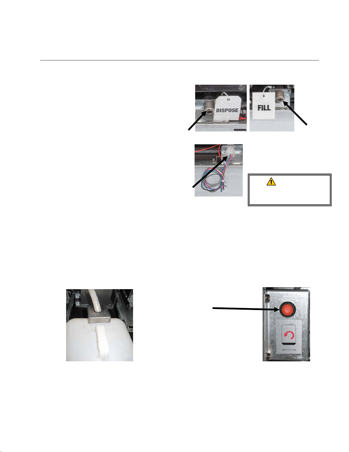
A–1
FILTERQUICK™ FQG30 SERIES GAS FRYER
APPENDIX A: BULK OIL INSTRUCTIONS
A.1.1 Bulk Oil Systems
Bulk oil systems have large oil storage
tanks, typically located in the rear of the
restaurant, that are connected to a rear
manifold on the fryer. Waste oil is
pumped from the fryer, via a fitting
located on the rear of the fryer labeled
DISPOSE (see Figure 1). , to the disposal
tanks and fresh oil is pumped from the
tanks, thru the fitting located on the rear of
the fryer labeled FILL, to the fryer (see
Figure 2). Connect the bulk oil
connections to plug located on the rear of
the fryer (see Figure 3). The wiring
diagram is located on the next page.
It is imperative that the fryer system be
completely power cycled after changing
any fresh or waste oil settings.
Figure 1 Figure 2
Figure 3
The FilterQuick
™
fryers, equipped for use
with bulk oil systems, have an onboard
fresh oil jug supplied by the bulk oil
provider. Remove the cap and insert the
standard fitting into the jug with the metal
cap resting on the lip of the jug. The oil is
pumped in and out of the jug through the
same fitting. (see Figure 4).
Figure 4
The momentary switch used to reset the ATO system is
also used to fill the jug in an fresh bulk oil system. After
clearing the TOP OFF EMPTY display, pressing and
holding the momentary switch, located above the JIB,
allows the operator to fill the jug from the bulk oil storage
tank (see Figure 5).
To fill the jug, press and hold the JIB reset button until the
jug is full, then release.*
NOTE: Do NOT overfill the
jug.
For instructions on filling the
vat from bulk, see the
FilterQuick Controller Manual
Section 1.9.8 page 1-16.
* NOTE: It takes approximately twelve seconds from the time the fill JIB button is pressed until the
fresh bulk oil pump starts. It may take up to 20 seconds before the level in the JIB begins to
rise. Typically it takes approximately three minutes to fill the JIB. It takes approximately
one minute to fill a split vat and two minutes to fill a full vat.
Fresh Oil
Connection
Waste Oil
Connection
WARNING:
Do not add HOT or
USED oil to a JIB.
Bulk wiring
connection
Figure 5
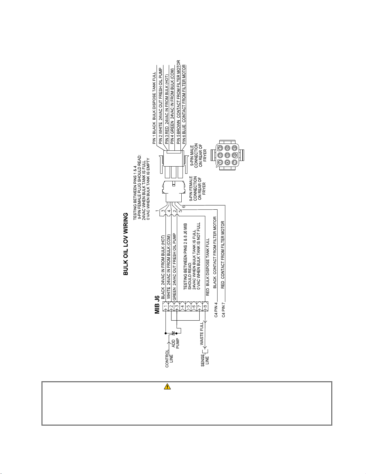
A–2
A.1.2 Bulk Oil Wiring
WARNING
The FilterQuick
™
fryer will ONLY operate with bulk oil systems that have a three-
pole float switch. If the float switch is the older two-pole switch, call the bulk oil
provider. These float switches are polarity specific which may short to ground
and damage an MIB board.
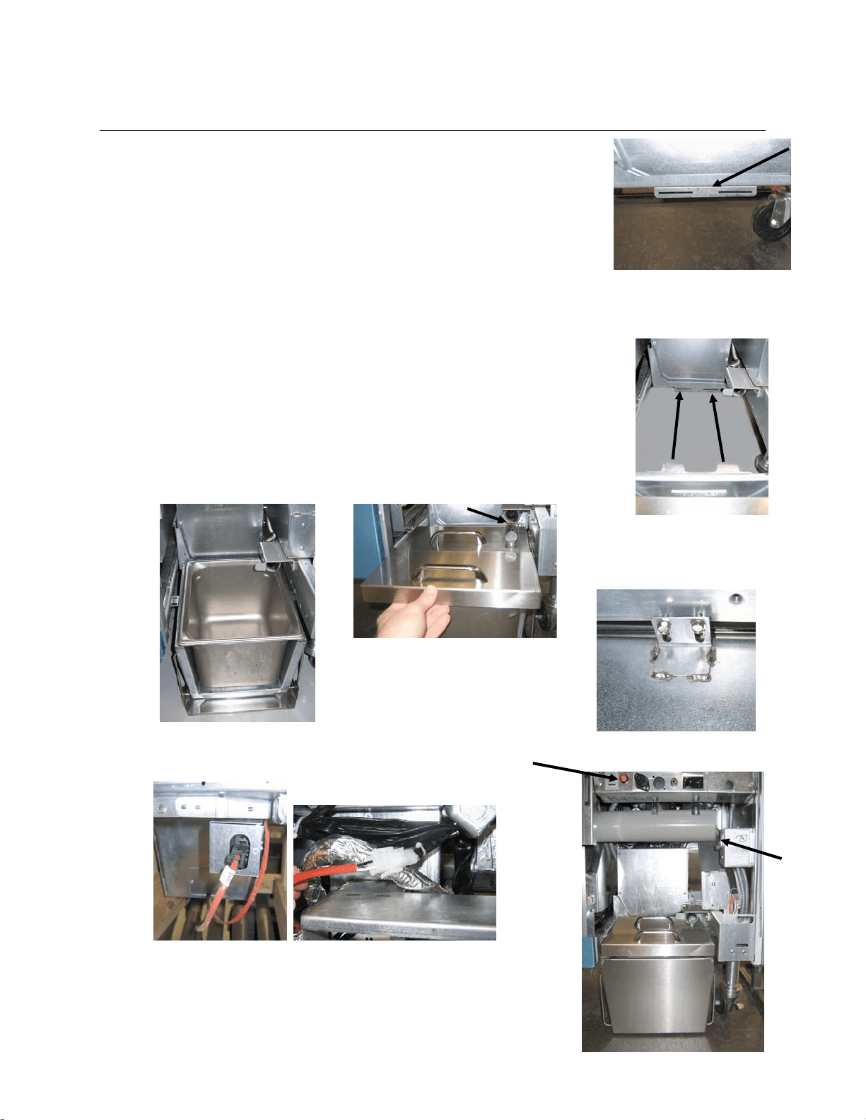
B–1
FILTERQUICK™ FQG30 SERIES GAS FRYER
APPENDIX B: JIB Preparation with Solid Shortening Option
1. Open right door of fryer and remove brace in JIB cabinet.
2. Attach alignment bracket to bottom of ATO box brace with
provided nuts. See Figure 1.
3. Position melting unit in front of cabinet.
4. Slide the melting unit tabs into the alignment guide slots. See
Figure 2.
5. With the melting unit inserted into the alignment guide bracket,
insert the inner oil reservoir pan into the tray. See Figure 3.
6. Place the melting unit lid on the unit and slide the oil pickup
tube nipple into the female suction receptacle. See Figure 4.
7. Use the provided screws to attach the melting unit to the
bottom of the interior rails on both sides using the existing
holes. See Figure 5.
8. On the back side of the melter, attach the white two-pin
connectors and plug in the black connector to the outlet box
shown in Figure 6.
9. Ensure the melting unit power switch is in the “ON” position.
See Figure 7.
Figure 1: Attach alignment bracket to
bottom of ATO box brace.
Orange button resets
system after a low oil
display.
Figure 6: Attach the two-pin white connectors and plug the
black connector into the utility box as shown. * Note the
position of the black connection may differ from photo.
Figure 2: Position the melter in the cabinet
and insert tabs into alignment guide slots.
Figure 3: Insert the inner oil
reservoir pan into the melting
unit.
Figure 4: Place the lid on the pan
and slide the oil pickup tube into
the female suction receptacle.
Figure 5: Attach the melting unit
to the rails on both sides.
Figure 7: The assembled melting
unit is shown in
p
osition.
Melting
unit
power
switch.
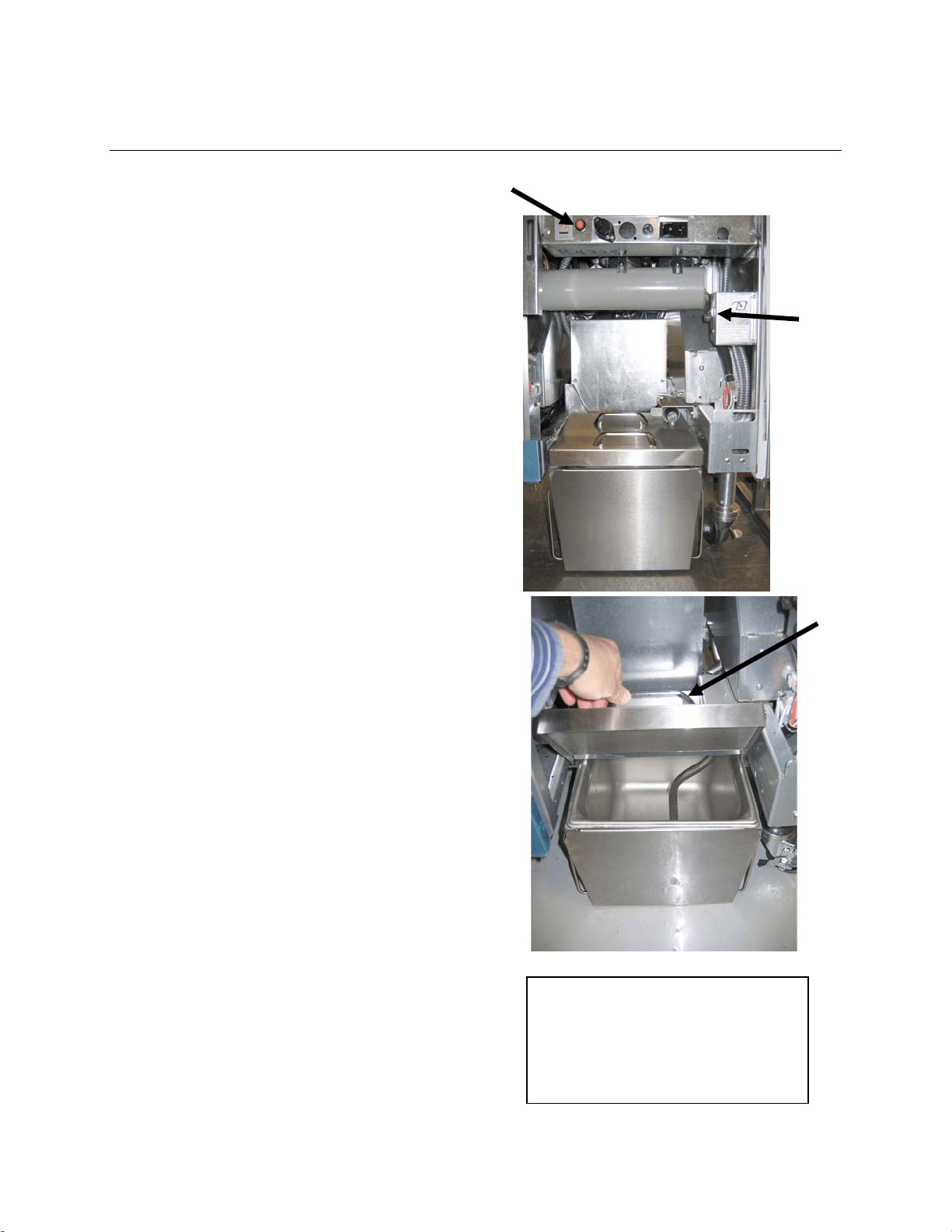
C–1
FILTERQUICK™ FQG30 SERIES GAS FRYER
APPENDIX C: Solid Shortening Melting Unit Use
Ensure shortening melting unit is on.
Fill melting unit with shortening.
Allow 2-3 hours for solid shortening to
melt. DO NOT attempt to use the top off
system with unmelted oil in the top off
system. The low oil message will be
displayed if the fryer calls for oil before
the shortening in the melting unit is
liquid.
Once the shortening is fully melted,
press and hold the orange reset button
to reset the top off system.
DO NOT ADD hot oil to the shortening
melter. The temperature of the oil
reservoir should not exceed 140°F
(60°C). Add small amounts of solid
shortening to the reservoir to ensure it
has sufficient oil to operate the top-off
system.
For best results, DO NOT TURN OFF
the solid shortening melting unit
overnight.
The power switch for the melting unit is
also used as a reset switch if the
system’s high limit temperature is
reached.
Melting
unit
power
switch
Reset oil reservoir system
Lift carefully
to add
shortening.
WARNING
The surfaces of the solid shortening
heater are hot. Do not touch with
bare hands. Wear protective clothing
when adding shortening to melting
unit.

THIS PAGE INTENTIONALLY LEFT BLANK
FRYMASTER
8700LINEAVENUE,SHREVEPORT,LA71106‐6800
318‐865‐1711
844‐724‐CARE(2273)
WWW.FRYMASTER.COM
Every new piece of Manitowoc Foodservice equipment comes with KitchenCare™ and you choose the level of service that meets
your operational needs from one restaurant to multiple locations.
StarCare
– Warranty & lifetime service, certified OEM parts, global parts inventory, performance audited
ExtraCare
– CareCode, 24/7 Support, online/mobile product information
LifeCare
– Install & equipment orientation, planned maintenance, KitchenConnect™, MenuConnect
Talk with KitchenCare™
- 1-844-724-CARE - www.mtwkitchencare.com
To learn how Manitowoc Foodservice and its leading brands can equip you, visit our global web site at
www.manitowocfoodservice.com, then discover the regional or local resources available to you.
©2014 Manitowoc Foodservice except where explicitly stated otherwise. All rights reserved. Continuing product improvement may necessitate change of specifications without notice.
Part Number FRY_IOM_8197052 06/2015
*8197052*