
Operator's Manual
CRRFTSMFIH
113 HP (Max. Developed)
2480 F.P.M. (No load)
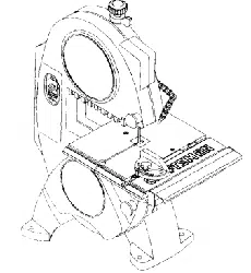
9" BAND SAW
Model No.
137.214090
/
/
/
/
CAUTION:
Before using this Band Saw,
read this manual and follow
all its Safety Rules and
Operating Instructions
• Safety Instructions
• Installation
• Operation
• Maintenance
• Parts List
• Espafiol
I Customer Help Line I
1-800-843-1682
Sears, Roebuck and Co., Hoffman Estates, IL 60179_
Visit our Craftsman website: www.sears.com/craftsman
Part No. 13721409001
SECTION PAGE
Warranty ...................................................................................................................................... 2
Products Specifications ................................................................................................................ 2
Safety Instructions ....................................................................................................................... 3
Accessories and Attachments ........................................................................................................ 6
Carton Contents .......................................................................................................................... 6
Know Your Band Saw ................................................................................................................... 7
Glossary of Terms ........................................................................................................................ 8
Assembly and Adjustments ........................................................................................................... 9
Operation .................................................................................................................................... 15
Maintenance ................................................................................................................................. 17
Troubleshooting Guide .................................................................................................................. 18
Parts ........................................................................................................................................... 20
Espahol ........................................................................................................................................ 22
FULL ONE YEAR WARRANTY
If this Band Saw fails clue to a defect in material or workmanship within one year of date of purchase,
Bears will at its option repair or replace it free of charge.
Return this Band Saw to a Sears Service Center for repair, or to place of purchase for replacement.
This warranty gives you specific legal rights, and you may also have other rights that may vary from state
to state.
Sears, Roebuck and Co., Dept. 817 WA, Hoffman Estates, IL 60179
Some dust created by power sanding, sawing, grinding, drilling and other construction activities contains chemicals
known to the state of California, to cause cancer, birth defects or other reproductive harm. Some examples of these
chemicals are:
Lead from lead-based paints
Crystalline silica from bricks, cement and other masonry products
• Arsenic and chromium from chemically treated lumber
Your risk from these exposures varies, depending on how often you do this type of work. To reduce your exposure to
these chemicals, work in a well-ventilated area and work with approved safety equipment such as dust masks that are
specially designed to filter out microscopic particles.
Motor
Power source ......... 120 V, 60 Hz, 2.5Amp., Ac
Speed ...................... 2480FPM (No load)
Speed control .......... Electronic
Horsepower ............ 1/3HP(Max. Developed)
Cutting Capacity
Throat .................. 9"
Height .................. 3-1/2"
Blade
Width .................... t/8" to 3/8_
Length .................. 59" to 59-1/_."
Table
Size .................... 12-1/4" x 11-1/:_'
Tilt ...................... 0° - 3° Left; O° - 45° Right
Table Extension ............ Yes, with fence
Extension fence Capacity. 12" Right
Sawdust blower ........................... Yes
Net weight .................................. 30.8 Ibs.
Toavoid electrical hazards, fire hazards, or damage to
the tool, use proper circuit protection. Use a separate
electrical circuit for your tools.
This Band Saw is wiredat the factory for 120V operation.
Connect to a 120V, 15AMP branch circuit and use a 15
Amp time delay fuse or circuit breaker. To avoid shock or
fire, replace power cord immediately if it is worn, cut or
damaged in any way.
GENERAL SAFETY INSTRUCTIONS
BEFORE USING THE BAND SAW
Safety isa combinationofcommon sense, staying alert
and knowingbow to usethis Band Saw.
To avoid mistakes that could cause serious injury,de not
plug the Band Saw in until you have read and
understood the following:
1. READ and become familiarwith the entire Operator's
Manual. LEARN the tool's application, limitationsand
possiblehazards,
2. KEEP GUARDS IN PLACE and in workingorder.
3, REMOVE ADJUSTING KEYS AND WRENCHES.
Form the habit of checking to see that keys and
adjustingwrenches are removed from the tool before
turning ON.
4. KEEP WORK AREA CLEAN. Cluttered areas and
benches inviteaccidents.
5. DON'T USE IN DANGEROUS ENVIRONMENT.
Don't use power toolsin damp or wet locations, or
expose them to rain, Keep work area well lighted.
6. KEEP CHILDREN AWAY.All visitors should be kept a
safe distance from work area.
7. MAKE WORKSHOP CHILD PROOF with padlocks,
master switches, or by removing starter keys.
8. DON'T FORCE THE TOOL. It will dothe job better
and safer at the rate for which it was designed.
9. USE THE RIGHT TOOL. Do not force tool or
attachment to do a)ob for whichit was not designed.
10.USE PROPER EXTENSION CORD. Make sure your
extension cord is in good condition. When using an
extension cord, be sure to use one heavy enough to
carp/the current your productwiltdrew. An
undersized cord willresult in a drop in line voltage
and in lossof powerthat willcause the tool to
overheat. The table onpage 5 shows the correctsize
to use depending on cord length and nameplate
ampere rating, tf in doubt,use the nextheavier gauge.
The smaller the gauge number,the heavier the cord.
11.WEAR PROPER APPAREL, Do not wear loose
clothing,gloves, neckties, rings, bracelets, or other
jewelry that may get caught in moving pads. Non-slip
footwear is recommended. Wear protective hair
covering tocontain longhair.
12.ALWAYS WEAR EYE PROTECTION. Any Band Saw
can throw foreign objectsinto the eyes that could
cause permanent eye damage. ALWAYS wear Safety
Goggles (not glasses) that comply withANSI Safety
standard Z87.1 Everyday eyeglasses have only
impact-resistance lenses. They ARE NOT safety
glasses. Safety Goggles are available at Sears.
NOTE: Glasses or goggles notin compliance with
ANSI Z87,1 could cause seriousinjury.
13.WEAR A FACE MASK OR DUST MASK. Sawing
operation produces dust.
14.SECURE WORK. Use clamps or a vise to holdwork
when practical. It's safer than usingyour hand and it
frees bothhands to operate tool.
15.DISCONNECT TOOLS before servicing;when
changingaccessories such as blades, bits, cutters,
and the like.
16.REDUCE THE RISK OF UNINTENTIONAL
STARTING. Make sure switch isin OFF position
before pluggingin.
17.USE RECOMMENDED ACCESSORIES. Consult the
Operator's Manual for recommended accessories.
The use of improperaccessories may cause serious
iniury.
18.NEVER STAND ON TOOL. Serious injury could
occur if the tool is tipped or if the cutting tool is
unintentionallycontacted.
19.CHECK FOR DAMAGED PARTS. Before further use
of the tool, a guard orother part that isdamaged
should be carefullychecked to determine that it will
operate properlyand perform its intended function -
check for alignmentof moving parts, bindingof
moving parfs, breakage of parts, mounting,and any
other conditionsthat may affect its operation.Aguard
or other part that isdamaged should be properly
repaired or replaced.
20.NEVER LEAVE TOOL RUNNING UNATTENDED.
TURN POWER "OFF". Don't leave tool untilit comes
to a complete stop.
21.DON'T OVERREACH. Keep proper footing and
balance at alltimes.
22.MAINTAIN TOOLS WITH CARE. Keep tools sharp
and clean for best and safest performance. Follow
instructionsforlubricatingand changing accessories.
23.DO NOT use power tools inthe presence of
flammable liquidsor gases.
i 3

24.DO NOT OPERATE the tool ifyou are under the
influence of any drugs,alcohol or medication that
could affect your abilityto use the tool propedy.
25.ALWAYS operate the band saw in a well-ventilated
area and provide for proper dust removal. Use dust
collection systems whenever possible. Dust
generated from certain materials can be hazardous to
your health,
SPECIFIC SAFETY INSTRUCTIONS FOR
BAND SAWS
TO AVOID INJURY from unexpected movement,
make sure the saw ison a firm, level surface,
propedy secured to prevent rocking. Make sure there
is adequate space for operating. Boltthe saw to a
supportsurface to prevent slipping,walking, or
slidingduring operation.
2. TURN the saw OFF and unplug the saw before
moving it.
3. USE THE CORRECT size and style of blade.
4. USE blades rated at 2480 FPM or greater.
5. MAKE SURE the blade teeth point down and
towards the table. t?lir=rl_,_=]Ol[_[e
6.
BLADE GUIDES, SUPPORT BEARINGS, AND
BLADE TENSION must be properlyadjusted to
avoid accidental blade contact and to minimize blade
breakage. To maximize blade support,always adjust
the upper blade guide and blade guard so that it is
1/8 inchabove the workpiece.
7. TABLE LOCK HANDLE should be tight.
8. USE EXTRA CAUTION with large, very small or
awkward workpieces.
9. USE EXTRA SUPPORTS to prevent workpieces
from slidingoff the table top. Never use another
person to supportthe workpiece.
10. WORKPIECES must be secured so they don't twist,
rock,or slip while being cut.
11. PLAN intricate and smallwork carefully to avoid
pinching the blade. Avoid awkward operation and
hand positionsto prevent accidental contactwiththe
blade.
12.
13.
14.
15.
16.
17.
SMALL PIECES should be secured withjigs or
fixtures. Do not hand hold pieces that are so small
your fingers are under the blade guard.
SUPPORT roundwork properly (with a V-block or
clamped to the miter gauge) to prevent it from rolling
and the blade from biting.
CUT only one workpiece at a time. Make sure the
table isclear of everything except the workpiece and
itsguides before you turn the saw on.
ALWAYS WATCH the saw run before each use. If
there isexcessive vibrationor unusual noise, stop
immediately.Turnthe saw OFF. Unplug it
immediately.Do not startthe saw again untilthe
problemhas been located and corrected.
TO FREE any jammed material, turn the switchOFF.
Remove the switch key and unplug the saw. Wait for
all moving partsto stop before removingjammed
material.
DON'T LEAVE the work area until all moving parts
are stopped. Tochild-proof the workshop, shut OFF
the power to master switchesand removethe switch
key from the band saw. Storeit in a safe place, away
from children.
For your own safety, read the entire instructionmanual
before operating the band saw.
1. Wear eye protection.
2. Do not wear gloves, necktie, or loose clothing.
3. Make sure the saw is on a firm level surface and
properly secured.
4. USE ONLY THE RECOMMENDED ACCESSORIES.
5. Use extra caution with very large, very small, or
awkward workpieces.
6. Keep hands away from the blade at all times to
prevent accidental injury.
7. Do not remove jammed cutoff pieces until the blade
has stopped.
8. Maintain proper adjustment of blade tension, blade
guides and thrust bearings.
9. Adjust upper guide to just clear the workpiece.
10. Hold the workpiece firmly against the table.
_ 4 _ ql
ELECTRICAL REQUIREMENTS
GROUNDING INSTRUCTIONS
IN THE EVENT OF A MALFUNCTION OR
BREAKDOWN, grounding provides a path of least
resistance for electric currentand reduces the risk of
electric shock. This tool isequipped with an electric cord
that has an equipment-grounding conductor anda
groundingplug. The plug MUST be plugged intoa
matching receptacle thatis properly installedand
grounded in accordance withALL local codes and
ordinances,
DO NOT MODIFY THE PLUG PROVIDED. If it willnot fit
the receptacle, have the proper receptacle installedby a
qualified electrician.
IMPROPER CONNECTION ofthe equipment-grounding
conductor can result in risk of electric shock.The
conductor withgreen insulation(with or without yellow
stripes) is the equipment-grounding conductor. If repair
or replacement of the electriccord or plug is necessary,
DO NOT connect the equipment-groundingconductorto
a live terminal.
CHECK with a qualified electrician or service person if
you do notcompletely understand the grounding
instructions,or if you are not sure the tool isproperly
grounded.
USE ONLY 3-WIRE EXTENSION CORDS THAT HAVE
3-PRONG GROUNDING PLUGS AND 3-POLE
RECEPTACLES THAT ACCEPT THE TOOL'S PLUG.
REPAIR OR REPLACE DAMAGED OR WORN CORD
IMMEDIATELY.
GUIDELINES FOR EXTENSION CORDS
USE PROPER EXTENSION CORD. Make sure your
extension cord is in good condition.When using an
extension cord, be sure to use one heavy enough to
carrythe currentyour productwill draw. An undersized
cord willcause a drop in line voltage, resulting in lossof
power and cause overheating. The table below shows
the correct size to usa depending on cord lengthand
nameplate ampere rating.If in doubt, use the next
heavier gauge. The smaller the gauge number,the
heavier the cord.
rRl_1 d='q]_[i
Be sure your extension cord is properly wired and in
good condition. Always replacea damaged extension
cord or have it repaired by a qualified personbefore
using it. Protectyour extensioncords from sharp objects,
excessive heat and damp or wet areas.
_lllb?lhWJllJlVlK_==lED_s--__l-- = ;;_:all=l_l_[o]_.|lKil|.-lls¢.a _yirJ[;
Use a separate electrical circuitfor your tools. This circuit
must not be lessthan # 12 wire and shouldbe protected
with a t 5 Amp time delay fuse. Before connectingthe
motor tothe power line, make sure the switch is in the
OFF positionand the electriccurrent is rated the same
as the current stamped on the motor nameplate.
Runningat a lower voltage will damage the motor.
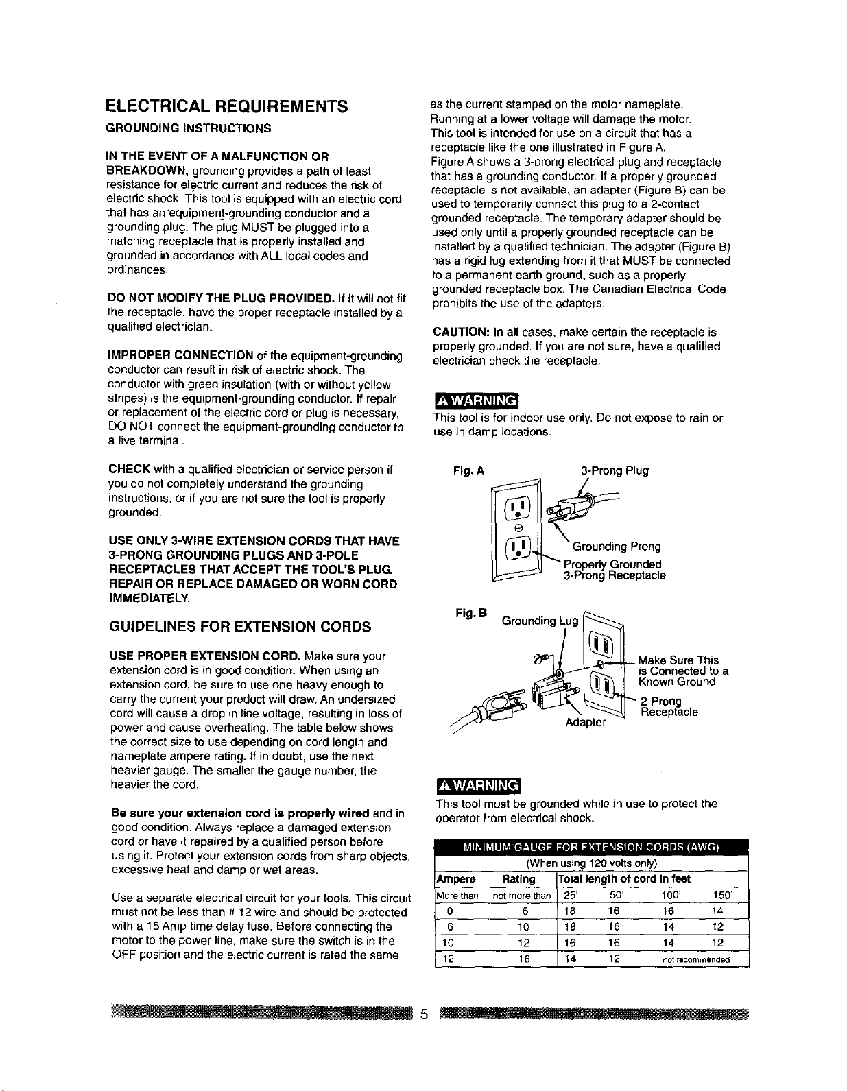
This tool is intended for use on a circuit that has a
receptacle like the one illustrated in Figure A.
Figure A shows a 3-prong electrical plug and receptacle
that has a grounding conductor. If a properly grounded
receptacle is not available, an adapter (Figure B) can be
used to temporarily connect this plug to a 2-contact
grounded receptacle. The temporary adapter should be
used only until a properly grounded receptacle can be
installed by a qualified technician. The adapter (Figure B)
has a rigid lug extending from it that MUST be connected
to a permanent earth ground, such as a properly
grounded receptacle box. The Canadian Electrical Code
prohibits the use of the adapters.
CAUTION: In all cases, make certain the receptacle is
properlygrounded. If you are not sure, have a qualified
electriciancheck the receptacle.
This tool isfor indoor use only.Do not expose to rain or
use in damp locations.
Fig. A
3-Preng Plug
g Prong
Properly Grounded
3-Prong Receptacle
Fig. B Grounding Lug
_'_/ I _(_n__ Make Sure This
F(_ rl is Connected to a
_ I _._L _ Known Ground
_ _.- I]_" 2-Prong
_-_3'=_1"__ "_. _ Receptacle
,///.:o_ Adapter
This toolmust be grounded while in use to protectthe
operator from electrical shock.
(When using 120 volts only)
Ampere Rating
Morethan notmorett_an
0 6
6 10
10 12
12 16
To_llengthofcordin feet
25' 50' 100' 150'
18 16 16 14
18 16 14 12
16 16 14 12
J14 12 notrecommended
_5
RECOMMENDED ACCESSORIES
To avoid injury:
Use only accessories recommended for this band
saw.
Follow instructions that accompany accessories. Use
of improperaccessories may cause hazards.
Use onlyaccessories designed for thisband saw to
avoid injury from thrownbroken parts or workpieces.
Do not use any accessory unless you have
completely read the instruction or operator's manual
for that accessory.
Visit your Sears Hardware Department or see the Sears
Power and Hand Tool Catalog for the following
accessories:
ITEM
Miter gauge
Blade width: 1/8" to 3/8"
Blade length: 59" to 59-1/4,"
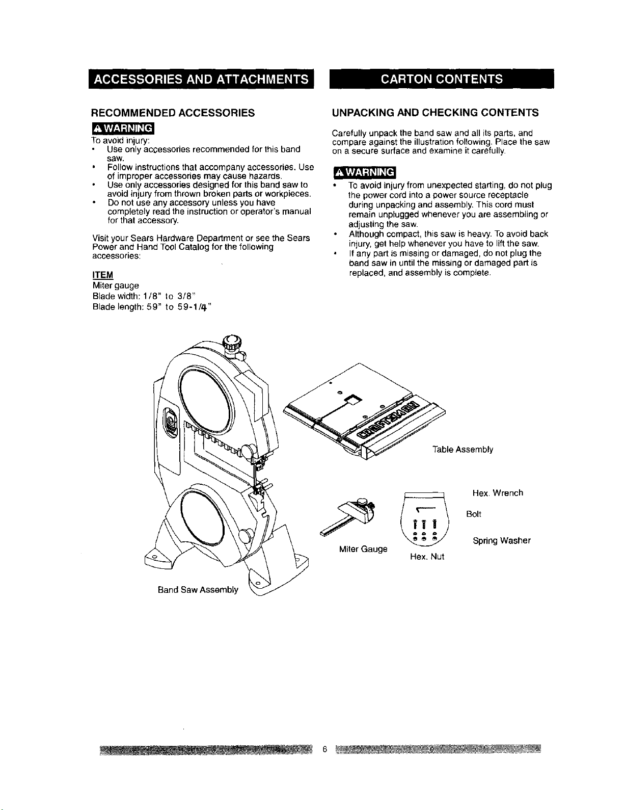
UNPACKING AND CHECKING CONTENTS
Carefully unpack the band saw and all its parts, and
compare against the illustration following. Place the saw
on a secure surface and examine it carefully.
Toavoid injuryfrom unexpected starting, do not plug
the power cord into a power source receptacle
during unpacking and assembly. This cord must
remain unplugged whenever you are assembling or
adjusting the saw.
Although compact, this saw is heavy. To avoid back
injury, get help whenever you have to lift the saw.
If any part is missing or damaged, do not plug the
band saw in until the missing or damaged part is
replaced, and assembly is complete.
Band Saw Assembly
_le Assembly
Hex. Wrench
! 2 Bolt
/_ Spring Washer
Miter
Gauge Hex. Nut
j-
6
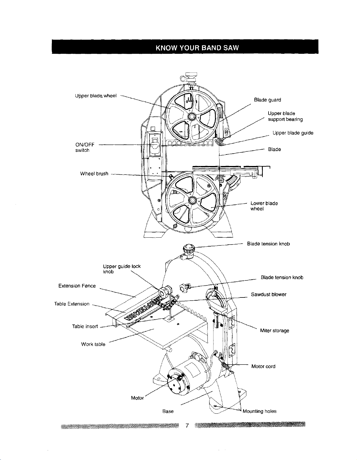
Upperblade,wheelswitchON/OFF
Wheelbrush
J
Blade guard
,_ Upper blade
_ _ support bearing
Upper blade guide
Blade
S
/ Lower blade
wheel
Blade tension knob
Extension Fence
Table Extension
Upper guide lock
knob
Blade tension knob
Sawdust blower
Table insert
Work table
Miter storage
Motor cord
Motor
Base
Mountingholes
7 _ f
BAND SAW TERMS
BLADE GUIDES -- Support the blade and keep it from
twisting during operation. Blade guides must be adjusted
when blade is changed or replaced.
UPPER GUIDE LOCK KNOB -- locks the upper slide.
Use it after adjusting the upper guide assembly to make
sure upper blade guide just clears workpiece before
cutting. Upper guide lock knob must be tightened before
the band saw is turned on.
TABLE LOCK KNOB -- locks the table in place,
TILT (BEVEL) SCALE -- shows the degree the table is
tilted for bevel cutting.
BLADE TENSION KNOB -- controls the amount of
blade tension when changing blades.
BLADE TRACKING KNOB -- adjusts blade position so
blade always runs in the center of the wheel.
SAWDUST PORT -- helps keep the machine free from
sawdust, The sawdust port makes an excellent hook-up
for a wet/dry vacuum.
ON/OFF SWITCH -- has a built-in child safety lock. To
lock the switch in the OFF position, remove the switch
key from the switch.
WOODWORKING TERMS
BEVEL CUT -- An angle cut made through the face of a
workpiece.
COMPOUND CUT -- A simultaneous bevel and miter
cut.
CROSSCUT -- A cut made across the width of the
workpiece.
F.P.M. -- Feet per minute. Used in reference to the
surface speed of the saw blade.
FREE HAND -- Performing a cut without using a fence
(guide), hold-down or other proper device to prevent the
workpiece from twisting during the cut'ling operation.
GUM -- Asticky sap-based residue from wood products.
HEEL -- Misalignment of the blade.
KERF -- The matedal removed by the blade in a through
cut, or the slot produced by the blade in a non-through or
partial cut.
LEADING EDGE -- The front edge of the workpiece
pushed into the cutting tool first.
MITER CUT -- An angle cut made across the width of a
workpiece.
RESAW -- A cutting operation to reduce the thickness of
the workpiece to make thinner workpiece.
RESIN -- A sticky sap that has hardened.
RIPPING CUT -- A cutting operation along the length of
the workpiece.
R.P.M. -- Revolutions per minute. The number of turns
completed by a spinning object in one minute.
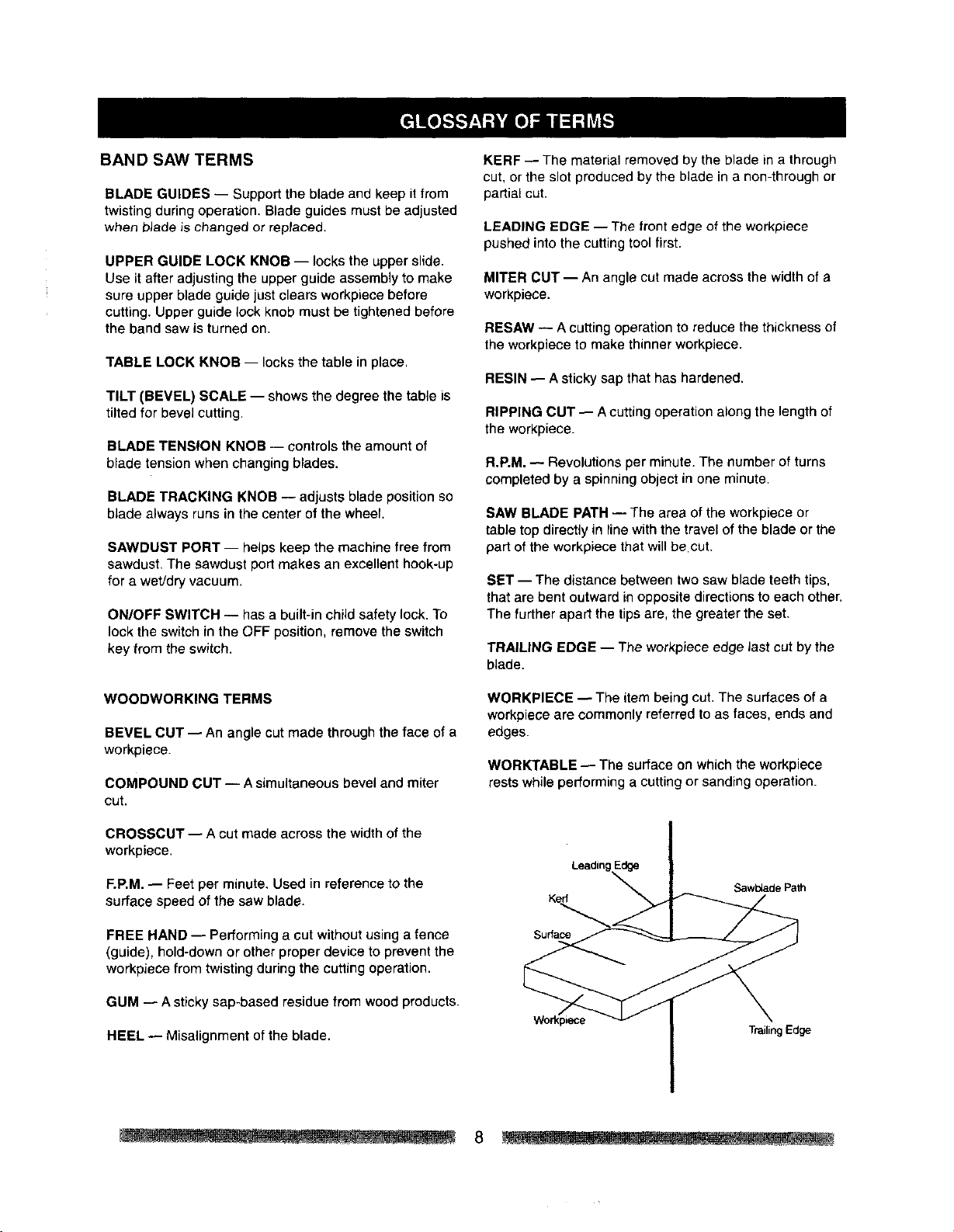
SAW BLADE PATH -- The area of the workpiece or
table top directly in line with the travel of the blade or the
part of the workpiece that will be.cut.
SET -- The distance between two saw blade teeth tips,
that are bent outward in opposite directions to each other.
The further apart the tips are, the greater the set.
TRAILING EDGE -- The workpiece edge last cut by the
blade.
WORKPIECE -- The item being cut. The surfaces of a
workpiece are commonly referred to as faces, ends and
edges.
WORKTABLE -- The surface on which the workpiece
rests while performing a cutting or sanding operation.
Leadin
Kerr
Surface
Sawlo_de Path
TrailingEdge
8
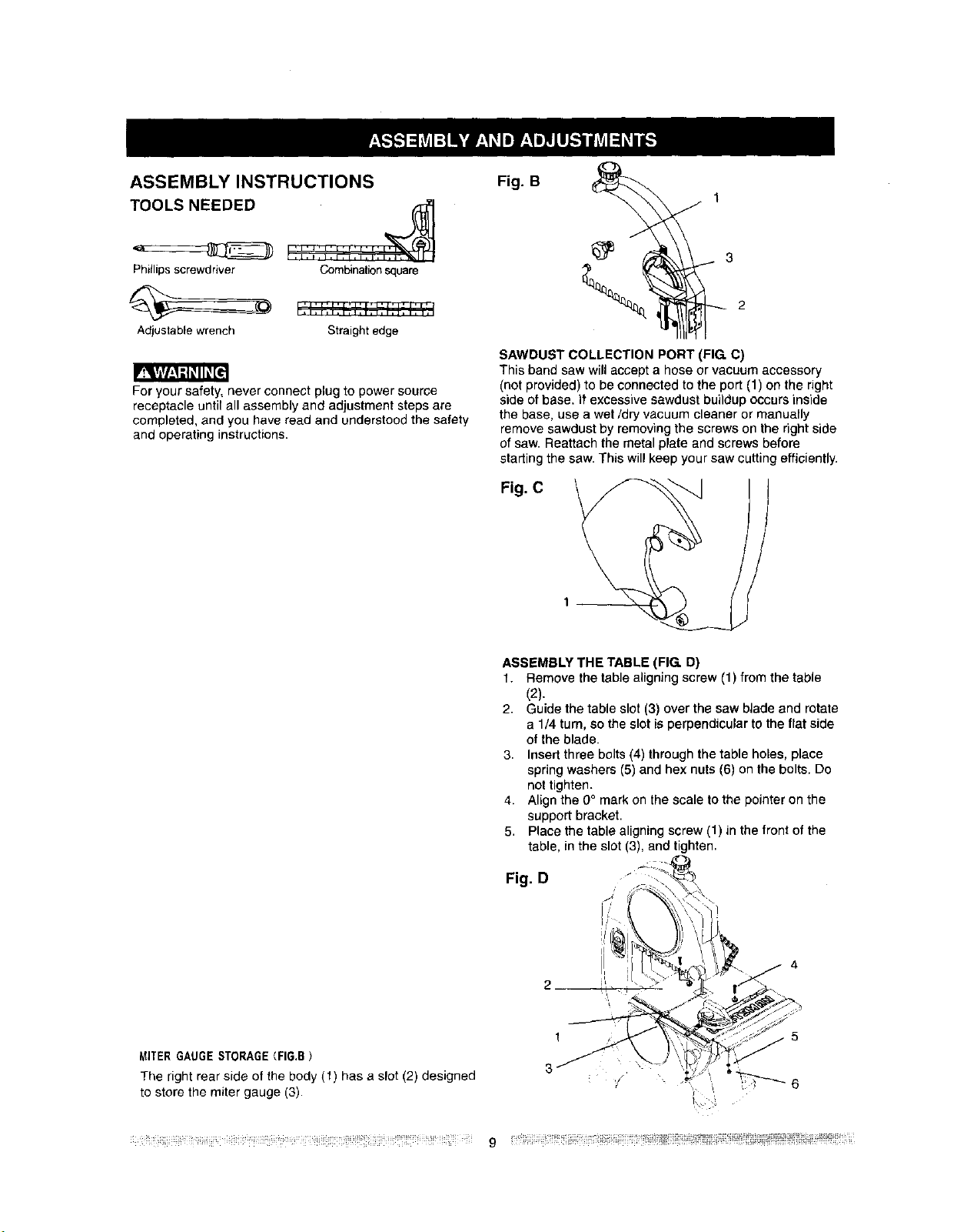
ASSEMBLY INSTRUCTIONS
TOOLS NEEDED
! ',I:',',IiIIIII:IZ I'
Phillipsscrewdriver Combinationsquare
Adjustablewrench Straightedge
r_w_ =W1F_G
For your safety, never connect plug to power source
receptacle until all assembly and adjustment steps are
completed, and you have read and understood the safety
and operating instructions.
Fig. B
SAWDUST COLLECTION PORT (FIG. C)
This band saw willaccept a hose or vacuum accessory
(not provided) to be connected to the port (1) on the right
side ofbase. It excessive sawdust buildup occurs inside
the base, use a wet/dry vacuum cleaner or manually
remove sawdust by removing the screws on the dgbt side
of saw. Reattach the metal plate and screws before
starting the saw. This will keep your saw cutting efficiently.
Fig. C
MITERGAUGESTORAGE(FIG.B}
The right rear side of the body (t) has a slot (2) designed
to store the miter gauge (3).
ASSEMBLY THE TABLE (FIG. D)
1. Remove the table aligning screw (1) from the table
(2).
2. Guide the table slot (3) over the saw blade and rotate
a 1/4 turn, so the slot is perpendicular to the flat side
of the blade.
3. Insert three bolts (4) through the table holes, place
spring washers (5) and hex nuts (6) on the bolts. Do
not tighten.
4. Align the 0° mark on the scale to the pointer on the
support bracket.
5. Place the table aligning screw (1) in the front of the
table, in the slot (3), and tighten.
Fig. D
2--
t
3
4
_ii!ili!!i_iiii!_iii_ili_i_i_ii!__i_!i_i!_i;!iiii_iiii!_i!_i_i!!!!!!i!i!i!ji!!!!ii?!!_!i!ii!i_!!!i?!iiii_!_!_!_!II_!I_!II!I-_! g !!_?_iii_i_!i_i!i_ii_ili;F!_!_!!i_ii!i!_!!_i!!!!_ii_ii_i!_!_ ii!_Fi_iiii:iiiil
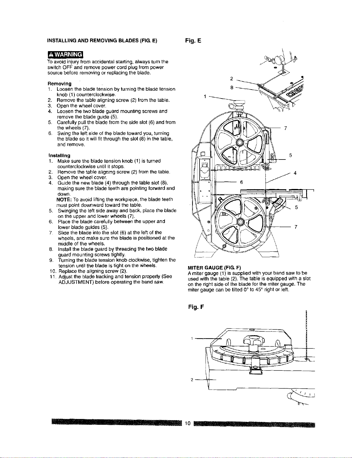
INSTALLINGAND REMOVING BLADES (FIG E) Fig. E
To avoid injuryfrom accidental starting, always turn the
switch OFF and remove power cord plug from power
source before removing or replacing the blade.
Removing
1. Loosenthe blade tension by turningthe blade tension
knob (1) counterclockwise.
2. Remove the table aligning screw (2) from the table.
3. Open the wheel cover.
4. Loosenthe two blade guard mountingscrews and
removethe blade guide (8).
8. Carefully pull the blade from the side slot (6) and from
the wheels (7),
6. Swing the left side ofthe blade toward you, turning
the blade so it willfit through the slot (8) in the table,
and remove.
Installing
1. Make sure the blade tension knob (1) isturned
counterclockwise until it stops.
2. Remove the table aligning screw (2) from the table.
3. Open the wheel cover.
4. Guide the new blade (4) through the table slot (8),
making sure the blade teeth are pointing forward and
down.
NOTE: To avoid lifting the workpiece, the blade teeth
must point downward toward the table.
5. Swinging the left side away and back, place the blade
on the upper and lower wheels (7).
6. Place the blade carefully between the upper and
lower blade guides (5).
7. Slide the blade into the slot (6) at the left of the
wheels, and make sure the blade is positioned at the
middle of the wheels.
8. Install the blade guard by threading the two blade
guard mounting screws tightly.
9. Turning the blade tension knob clockwise, tighten the
tension until the blade is tight on the wheels.
10. Replace the aligning screw (2).
11. Adjust the blade tracking and tension properly (See
ADJUSTMENT) before operating the band saw.
2
m 7
5
-- 7
MITER GAUGE (FIG. F)
Amiter gauge (1) is supplied with your band saw to be
used with the table (2). The table isequipped with a slot
on the right side of the blade for the miter gauge. The
miter gauge can be tilted 0° to 45° right or left.
Fig. F
2--
pl I'_ .I.... 10 -- _1[ I 'I' _I[I' _._! ......
BLADE TENSION (FIG I)
P_wi,r;g,_!-']_l!_[I
p"_Wk_vl_,ld_l]_[e:
Toavoid injury, turnthe switch OFF and unplugthe band
saw from '_hepower source before making any
adjustments.
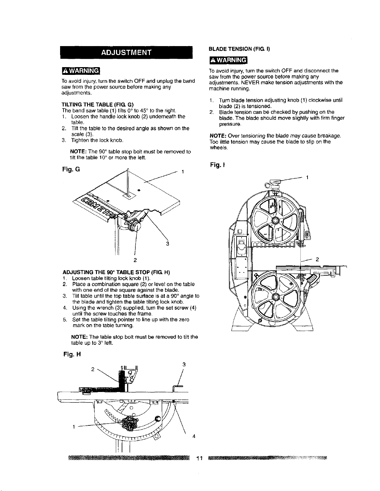
TILTING THE TABLE (FIG. G)
The band saw table (1) tilts 0" to 45° to the right.
1. Loosen the handle lock knob (2) underneath the
table.
2. Tilt the table to the desired angle as shown on the
scale (3).
3. Tighten the lock knob.
NOTE: The 90° table stop bolt must be removed to
tilt the table 10° or more the left.
Fig. G
To avoid injury, turn the switch OFF and disconnect the
saw from the power source before making any
adjustments. NEVER make tension adjustments with the
machine running.
1. Turn blade tension adjusting knob (1) clockwise until
blade (2) is tensioned.
2. Blade tension can be checked by pushing on the
blade. The blade should move slightly with firm finger
pressure.
NOTE: Over tensioning the blade may cause breakage,
Too little tension may cause the blade to slip on the
wheels.
Fig. I
ADJUSTING THE 90° TABLE STOP (FIG. H)
1. Loosen table tilting lock knob (1).
2. Place a combinationsquare (2) or level on the table
with one end of the square against the blade.
3. Tilt table untilthe top table surface isat a 90° angle to
the blade and tightenthe table tiltinglock knob.
4. Using the wrench (3) supplied, turn the set screw (4)
untilthe screw touches the frame,
5. Set the table tiltingpointer to line up withthe zero
mark on the table turning.
NOTE: The table stop bolt must be removed to tilt the
table up to 3° left.
Fig. H
3
4
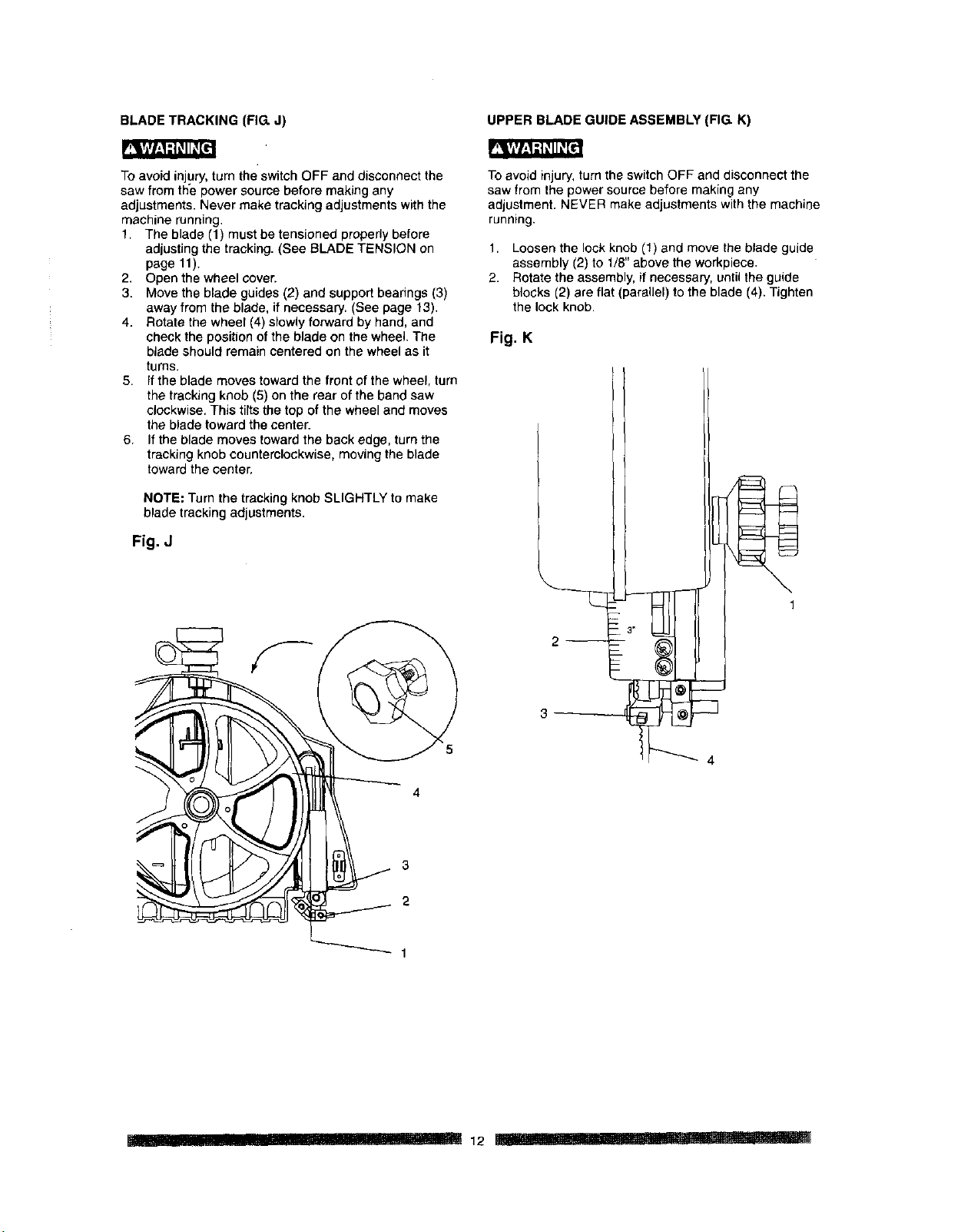
BLADE TRACKING (FIG. J) UPPER BLADE GUIDE ASSEMBLY (FIG K)
_l___l_ll_[l
To avoid injury turn the switch OFF and disconnect the
saw from the power source before making any
adjustments Never make tracking adjustments with the
machine running
1 The blade (1) must be tensioned properly before
adjusting the tracking (See BLADE TENSION on
page 11)
2 Open the wheel cover
3 Move the blade guides (2) and support bearings (3)
away from the blade if necessary (See page 13)
4 Rotate the wheel (4) slowly forward by hand and
check the position of the blade on the wheel The
blade should remain centered on the wheel as it
turns
5 Ifthe blade moves toward the front of the wheel turn
the tracking knob (5) on the rear of the band saw
clockwise This tilts the top of the wheel and moves
the blade toward the center
6 If the blade moves toward the back edge turn the
tracking knob counterclockwise moving the blade
toward the center
NOTE: Turn the tracking knob SLIGHTLY to make
blade trackingadjustments
Fig. J
3
2
To avoid injury turn the switch OFF and disconnect tile
saw from the power source before making any
adjustment NEVER make adjustments with the machine
running
1 Loosen the lock knob (1) and move the blade guide
assembly (2) to 1/8 above the workpiece
2 Rotate the assembly if necessary until the guide
blocks (2) are flat (parallel) to the blade (4) Tighten
the lock knob
Fig. K
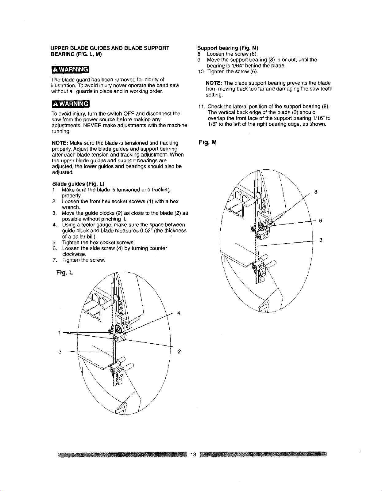
UPPER BLADE GUIDES AND BLADE SUPPORT
BEARING (FIG. L, M)
The blade guard has been removed for clanty of
illustration. To avoid injury never operate the band saw
without all guards in place and in working order,
To avoid iniury, turn the switch OFF and disconnect the
saw from the power source before making any
adjustments. NEVER make adjustments with the machine
running.
NOTE: Make sure the blade is tensioned and tracking
properly. Adjust the blade guides and support bearing
after each blade tension and tracking adjustment. When
the upper blade guides and support bearings are
adjusted, the lower guides and bearings should also be
adjusted.
Blade guides (Fig. L)
1. Make sure the blade is tensioned and tracking
properly.
2. Loosenthe front hex socket screws (1) with e hex
wrench.
3. Move the guide blocks (2) as close to the blade (2) as
possible withoutpinchingit.
4. Using a feeler gauge, make sure the space between
guide block and blade measures 0.02" (the thickness
of a dollar bill),
5. Tightenthe hex socket screws.
6. Loosen the side screw (4) byturningcounter
clockwise.
7. Tighten the screw.
Fig. L
Support bearing (Fig. M)
8. Loosen the screw (6).
9. Move the support bearing (8) in or out, until the
bearing is 1/64" behind the blade.
10. Tighten the screw (6).
NOTE: The blade support bearing prevents the blade
from moving back too far and damaging the saw teeth
setting.
11.
Check the lateral position of the support bearing (8).
The vertical back edge of the blade (3) should
overlap the front face of the support bearing 1/16" to
1/8" to the le_lof the right bearing edge, as shown.
Fig. M
8
6
3
2
-- 13 . .
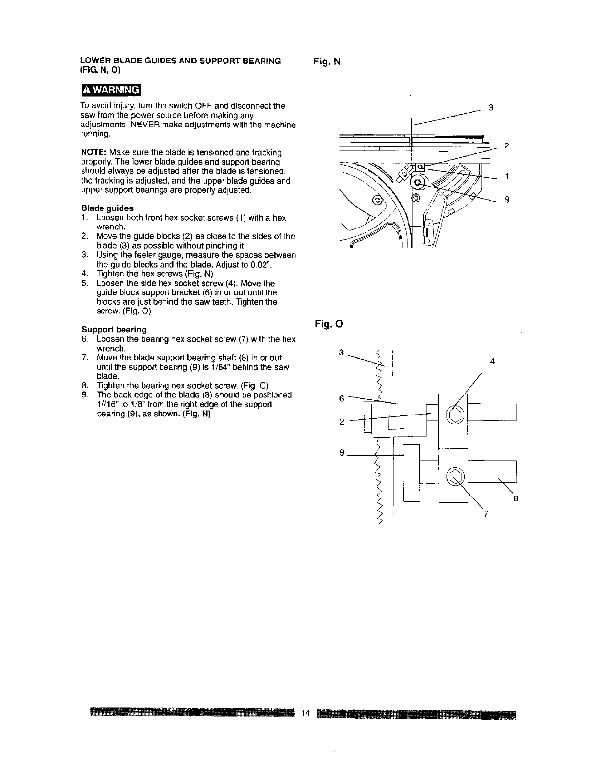
LOWER BLADE GUIDES AND SUPPORT BEARING Fig. N
(FiGN, O)
Toavoid injury, turn the switch OFF and disconnect the
saw from the power source before making any
adjustments. NEVER make adjustments with the machine
running.
NOTE: Make sure the blade is tensioned and tracking
properly. The lower blade guides and support bearing
should always be adjusted after the blade is tensioned,
the tracking is adjusted, and the upper blade guides and
upper support bearings are properly adjusted.
Blade guides
1. Loosen both front hex socket screws (1) with a hex
wrench.
2. Move the guide blocks (2) as close to the sides of the
blade (3) as possible without pinching it.
3. Using the feeler gauge, measure the spaces between
the guide blocks and the blade. Adjust to 0.02".
4. Tighten the hex screws (Fig. N)
5. Loosen the side hex socket screw (4). Move the
guide block support bracket (6) in or out until the
blocks are just behind the saw teeth. Tighten the
screw. (Fig. O)
Support bearing
6. Loosen the bearing hex socket screw (7) with the hex
wrench.
7. Move the blade support beadng shaft (8) in or out
until the support bearing (9) is 1/64" behind the saw
blade.
8. Tighten the bearing hex socket screw. (Fig. O)
9. The back edge of the blade (3) should be positioned
1//16" to 1/8" from the right edge of the suppod
bearing (9), as shown. (Fig. N)
3
i
2
/
t
9
Fig. O
F!%
9
\ 8
7
.... l 14
BASIC SAW OPERATIONS
¥.'_I.W'_1:1_II_e:
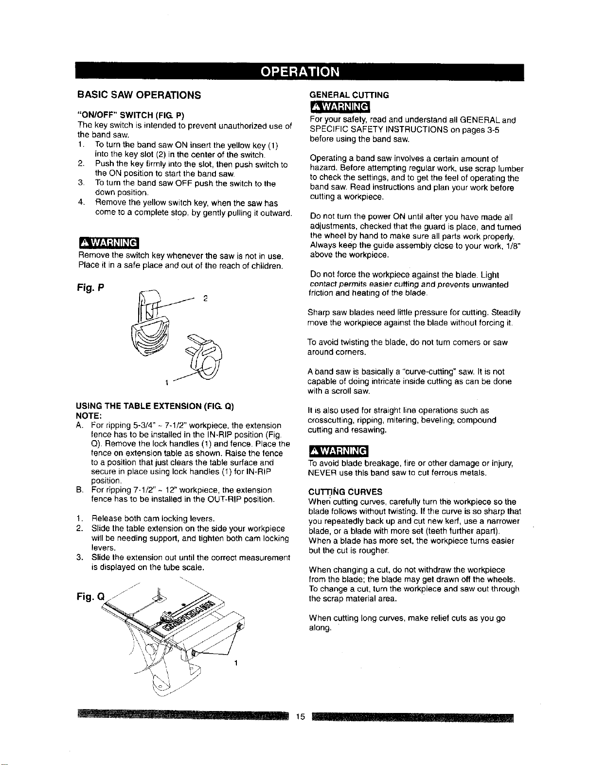
"ON/OFF" SWITCH (FIG. P)
The key switchis intended to prevent unauthorizeduse of
the band saw.
1. To turnthe band saw ON insert the yellowkey (1)
intothe key slot (2) inthe center of the switch.
2. Pushthe key firmlyintothe slot, then push switchto
the ON positionto start the band saw.
3. To turnthe band saw OFF push the switchto the
down position.
4. Remove the yellow switchkey, when the saw has
come to a complete stop, by gently pullingitoutward.
Remove the switch key whenever the saw is not in use.
Place it in a safe place and out of the reach of children.
Fig. P
USING THE TABLE EXTENSION (FIG. Q)
NOTE:
A. For ripping 5-3/4" - 7-1/2" workpiece, the extension
fence has to be installed in the IN-RIP position (Fig.
Q). Remove the lock handles (1) and fence. Place the
fence on extension table as shown. Raise the fence
to a position that just clears the table surface and
secure in place using lock handles (1) for IN-RIP
position.
B. For ripping 7-1/2" - 12" workpiece, the extension
fence has to be installed in the OUT-RIP position.
t. Release both cam locking levers.
2. Slide the table extension on the side your workpiece
will be needing support, and tighten both cam locking
levers.
3. Slide the extension out until the correct measurement
is displayed on the tube scale.
if"
Fig
\
j_
GENERAL CuI-rlNG
For your safety, read and understand all GENERAL and
SPECIFIC SAFETY INSTRUCTIONS on pages 3-5
before using the band saw.
Operating a band saw involves a certain amount of
hazard. Before attempting regular work, use scrap lumber
to check the settings, and to get the feel of operating the
band saw. Read instructions and plan your work before
cutting a workpiece.
Do not turn the power ON until after you have made all
adjustments, checked that the guard is place, and turned
the wheel by hand to make sure all parts work properly.
Always keep the guide assembly close to your work, 1/8"
above the workpiece.
Do not force the workpiece against the blade. Light
contact permits easier cutting and prevents unwanted
friction and heating of the blade.
Sharp saw blades need little pressure for cutting. Steadily
move the workpiece against the blade without forcing it.
To avoid twisting the blade, do not turn corners or saw
around corners.
Aband saw is basically a "curve-cutting" saw. Itis not
capable of doing intricate inside cutting as can be done
with a scroll saw.
It isalso used for straight line operations such as
crosscutting, ripping, mitering, beveling; compound
cutting and resawing.
To avoid blade breakage, fire or other damage or injury,
NEVER use this band saw to cut ferrous metals.
CUT'FING CURVES
Whet; cuttingcurves, carefullyturn the workpiece so the
blade followswithouttwisting. If the curve isso sharp that
you repeatedly back up and cut new kerf, usea narrower
blade, or a blade withmore set (teeth further apad).
When a blade has more set, the workpiece turns easier
but the cut is rougher.
When changing a cut, do not withdraw the workpiece
from the blade; the blade may get drawn off the wheels.
To change a cut, turn the workpiece and saw out through
the scrap material area.
When cutting long curves, make relief cuts as you go
along.
..... 15

CIRCLE CUTTING (FIG. R)
1. Adjustthe guide assembly to 1/8" above the
workpiece.
2. Use both hands while feeding the work into the blade.
Ho_dthe workpiece firmly against the table. Use
gentle pressure. Do not force the work, allow the
blade to cqt.
3. The smallest diameter circle that can be cut is
determined by the width of the blade. For example, a
1/4" wide blade will cut a minimum diameter of
approximately 1-1/2".
Fig. R
MinirP_Jrn
i/2"O 1"D 2 I/Z" O Circle D_meler
lf_" Blad e W_ith
BLADE SELECTION (FIG. S)
CAUTION: Blade teeth are sharp. Use care when
handling a saw blade.
For longest wear and best cutting results, use the correct
blade thickness, width, and temper for the type of material
you will cut.
When sawing smalJcurves and delicate work, use narrow
blades. Otherwise, use the widest blade possible. See
Fig. R on page 15.
For cutting wood and similar materials with this band saw,
purchase blades in widths up to 1/2", and a length o159"
to 59-1/4-".
Do not cut metals with this band saw.
Common causes of blade breakage:
• Poor guide alignment and adjustment.
• Forcing or twisting a wide blade around a short
radius.
• Feeding too fast.
• Dull teeth of not enough set.
• Too much blade tension.
• Setting top guide assembly too high above the
workplace.
• Lumpy or improperly finished braze or weld on the
blade.
• Continuous running of blade when not cutting.
Fig. S
Operation
Cross Cutting
M,tenn
_ttin_
Circle C_
Curve Cuttin__
Recommended Blade
Width (Inches)
1/4, 3/8, 1/2
1/4, 3/8, 1/2
1/4, 3/8, 1/2
1/4, 3/8, 1/2
See chart on this a_age
1/8, 1/4
16
GENERAL MAINTENANCE
For your own safety, turn the switchOFF and remove
the plug from the power source receptacle before
maintaining, cleaning, adjusting, or lubricating your
sew,
TOavoid fire or toxic reaction, never use gasoline,
naphtha, acetone, lacquer thinner or similar highly
volatile solvents to clean the band saw.
To avoid eye injury from blowing debris, wear safety
goggles when blowing out sawdust.
BAND SAW
Sawdust will accumulate under the table and base.
This could cause difficulty in the movement of the
table when setting up a band saw cut. Frequently
blow out or vacuum up the sawdust.
Keep your band saw clean. Remove the sawdust
from the inside. Vacuum or blow out frequently.
Do not allow filth to build up on the table, the guides,
or the support bearings. Clean them with Craftsman
Gum and Pitch Remover.
NOTE: Do not immerse the support bearings in the
gum and pitch remover.
Put a thin coat of paste wax on the table so that the
wood slides easily white cutting.
BLADE WHEEL TIRES
Pitch and sawdust that build up on the tiros should be
removed with a stiff brush or scraped off with a piece
of wood.
NOTE: To avoid damaging the tires do not use a
sharp knife or any kind of solvent.
When the tires become worn they should be replaced.
When replacing the tires, stretch them around the
wheels but do not glue them on.
MOTOR
Frequently blow or vacuum out any sawdust from the
motor. Follow lubrication instruction on the motor
label.
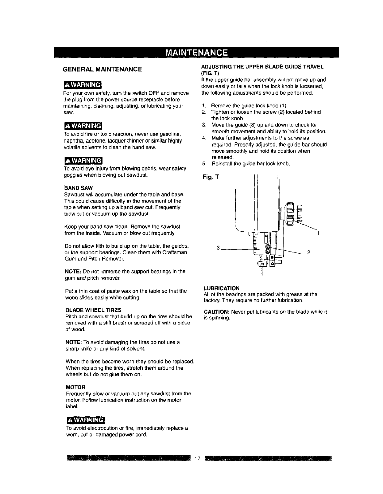
ADJUSTING THE UPPER BLADE GUIDE TRAVEL
(FIG, T)
If the upper guide bar assembly will not move up and
down easily or fails when the lock knob is loosened,
the following adjustments should be performed.
1, Remove the guide lock knob (1)
2. Tighten or loosen the screw (2) located behind
the lock knob.
3, Move the guide (3) up and down to check for
smooth movement and ability to hold its position.
4. Make further adjustments to the screw as
required. Properly adjusted, the guide bar should
move smoothlyand hold its position when
released.
5. Reinstall the guide bar lock knob.
Fig, T
3
2
LUBRICATION
All of the bearings are packed with grease at the
Iactoe/. They require no further lubrication.
CAUTION: Never put lubricants on the blade while it
is spinning.
To avoid electrocution or fire, immediately replace a
worn, cut or damaged power cord.
r ,,,,,!,,,,,,,,, I1! II t7 .
To avoid injuryfrom an accidental start, turn the switch OFF and remove the ptug from the power source before
making any adjustments.
All electrical or mechanical repairs should be done only by qualified service technicians. Contact the nearest Sears
Service Center.
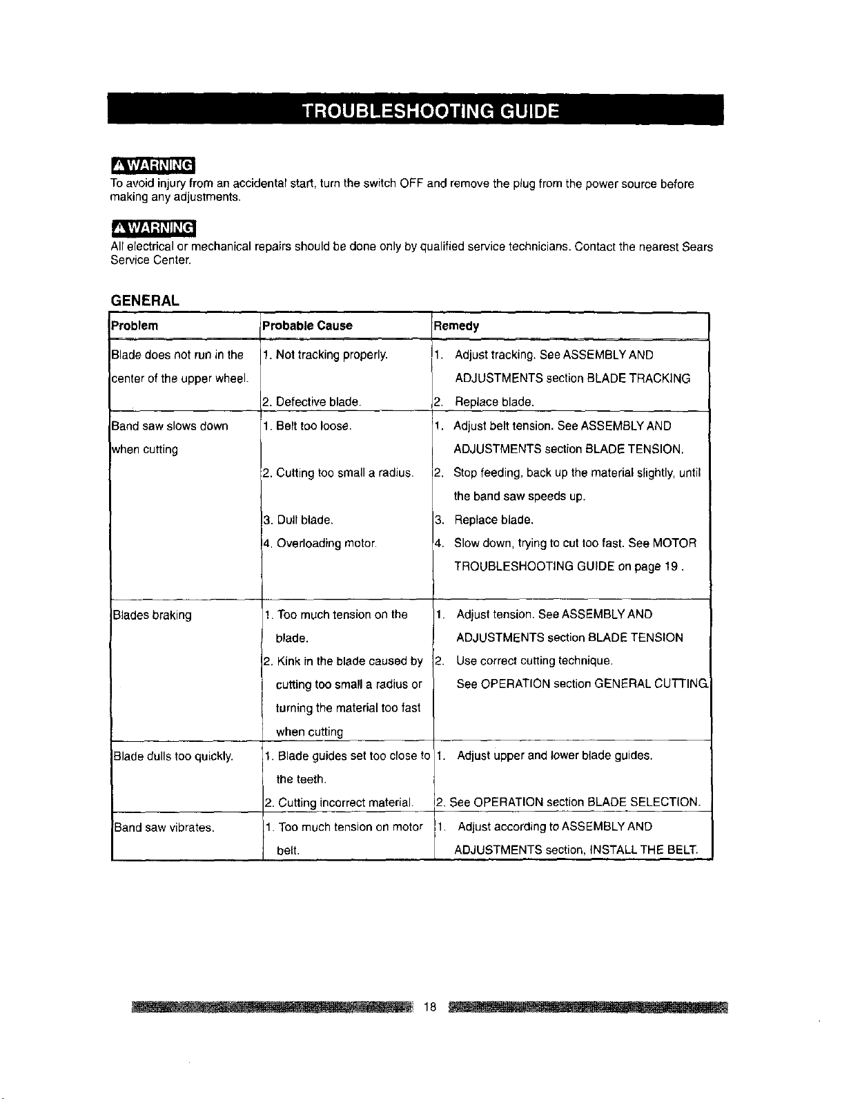
GENERAL
Problem
Blade does not run in the
center of the upper wheel.
Band saw slows down
when cutting
Blades braking
Blade dulls too quickly.
Band saw vibrates.
Probable Cause
1. Not tracking properly.
2. Defective blade, 2.
1. Belt too loose. 1.
2. Cutting too small a radius. 2.
3. Dull blade. 3.
4. Overloading motor. 4.
Remedy
1. Adjust tracking. See ASSEMBLY AND
ADJUSTMENTS section BLADE TRACKING
Replace blade.
Adjust belt tension. See ASSEMBLY AND
ADJUSTMENTS section BLADE TENSION.
Stop feeding, back up the material slightly, until
the band saw speeds up.
Replace blade.
Slow down. trying to cut too fast. See MOTOR
TROUBLESHOOTING GUIDE on page 19.
!. Too much tension on the 1.
blade.
2. Kink in the blade caused by 2.
cutting too small a radius or
turning the material too fast
when cutting
t. Blade guides set too close to I.
the teeth.
2. Cutting incorrect material.
1. Too much tension on motor
belt.
Adjust tension. See ASSEMBLY AND
ADJUSTMENTS section BLADE TENSION
Use correct cutting technique.
See OPERATION section GENERAL CUTTING,
Adjust upper and lower blade guides.
2. See OPERATION section BLADE SELECTION.
1. Adjust according to ASSEMBLY AND
ADJUSTMENTS section, INSTALL THE BELT.
18
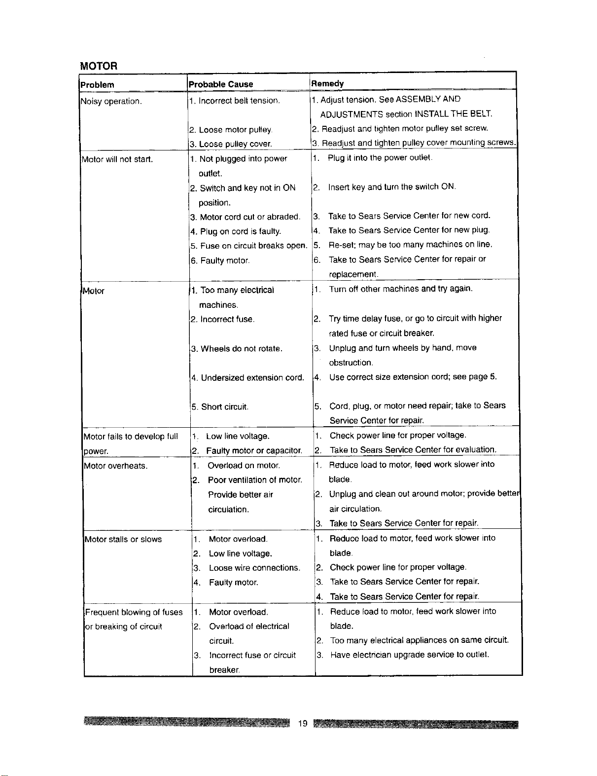
MOTOR
Problem
'qoisy operation.
Motor will not start.
Motor
Vlotor fails to develop full
_ower.
rioter overheats.
Motor stalls or slows
Frequent blowing of fuses
or breaking of circuit
Probable Cause
1. Incorrect belt tension.
2. Loose motor pulley.
3. Loose pulley cover.
1. Not plugged into power
outlet.
2. Switch and key not in ON
position.
3. Motor cord cut or abraded.
4. Plug on cord is faulty.
5. Fuse on circuit breaks open.
6. Faulty motor.
1. Too many electrical
machines.
2. Incorrect fuse.
3. Wheels do not rotate.
4. Undersized extension cord.
5. Short circuit.
t. Lowline voltage.
__. Faulty motor or capacitor.
1. Overload on motor.
2. Poor ventilation of motor.
Provide better air
circulation.
1. Motor overload.
2. Low line voltage.
3. Loose wire connections.
4. Faulty motor.
1. Motor overload.
2. Overload of electrical
circuit.
3. Incorrect fuse or circuit
breaker.
IRemedy
1. Adjust tension. See ASSEMBLY AND
ADJUSTMENTS section iNSTALL THE BELT.
2. Readjust and tighten motor pulley set screw.
3. Readjust and tighten pulley cover mounting screws
. Plug it into the power outlet.
2. Insert key and turn the switch ON.
3. Take to Sears Service Center for new cord.
4. Take to Sears Service Center for new plug.
5. Re-set; may be too many machines on line.
6. Take to Sears Service Center for repair or
replacement.
i1. Turn off other machines and try again.
2. Try time delay fuse, or go to circuit with higher
rated fuse or circuit breaker.
3. Unplug and turn wheels by hand. move
obstruction.
$. Use correct size extension cord; see page 5.
5. Cord, plug. or motor need repair; take to Sears
Service Center for repair.
1. Check power line for proper voltage.
2. Take to Sears Service Center for evaluation.
1. Reduce load to motor, feed work slower into
blade.
2. Unplug and clean out around motor; provide bette
air circulation.
3. Take to Sears Service Center for repair.
1. Reduce load to motor, feed work slower into
blade.
2. Check power line for proper voltage.
3. Take to Sears Service Center for repair.
4. Take to Sears Service Center for repair.
1. Reduce load to motor, feed work slower into
blade.
2. Too many electrical appliances on same circuit.
3. Have electrician upgrade service to outlet.
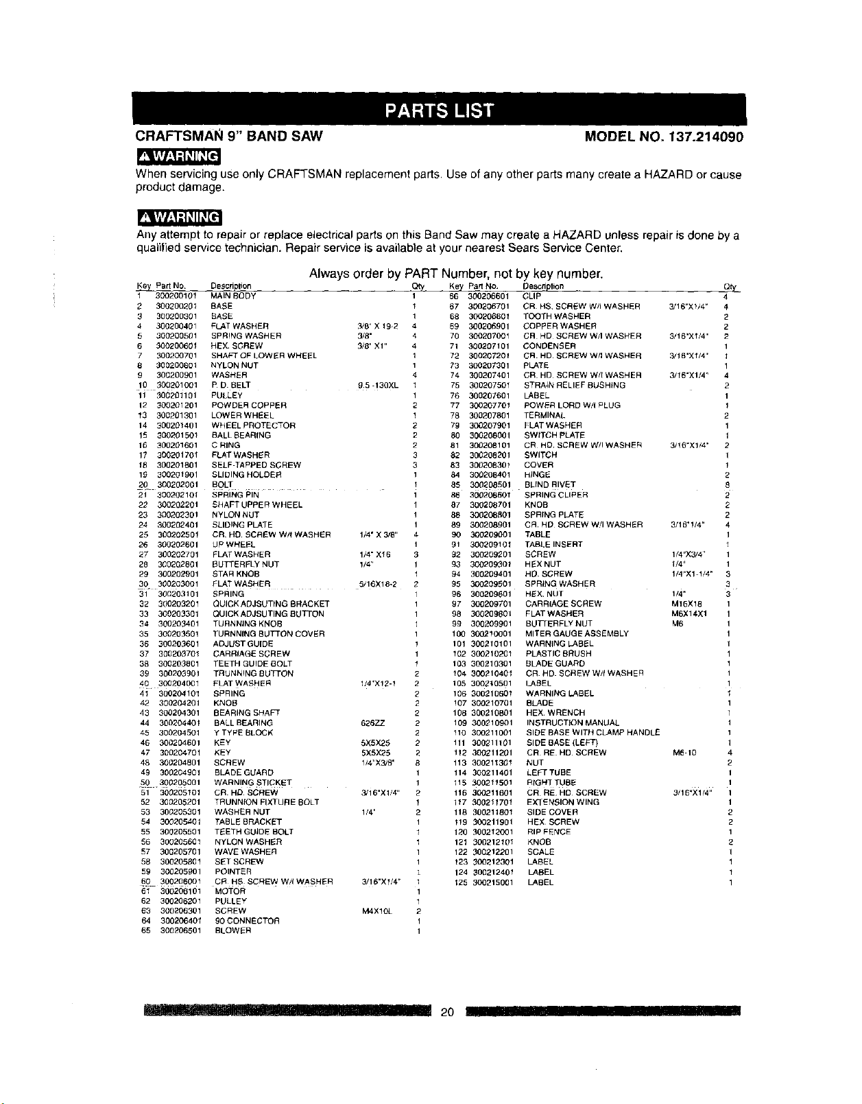
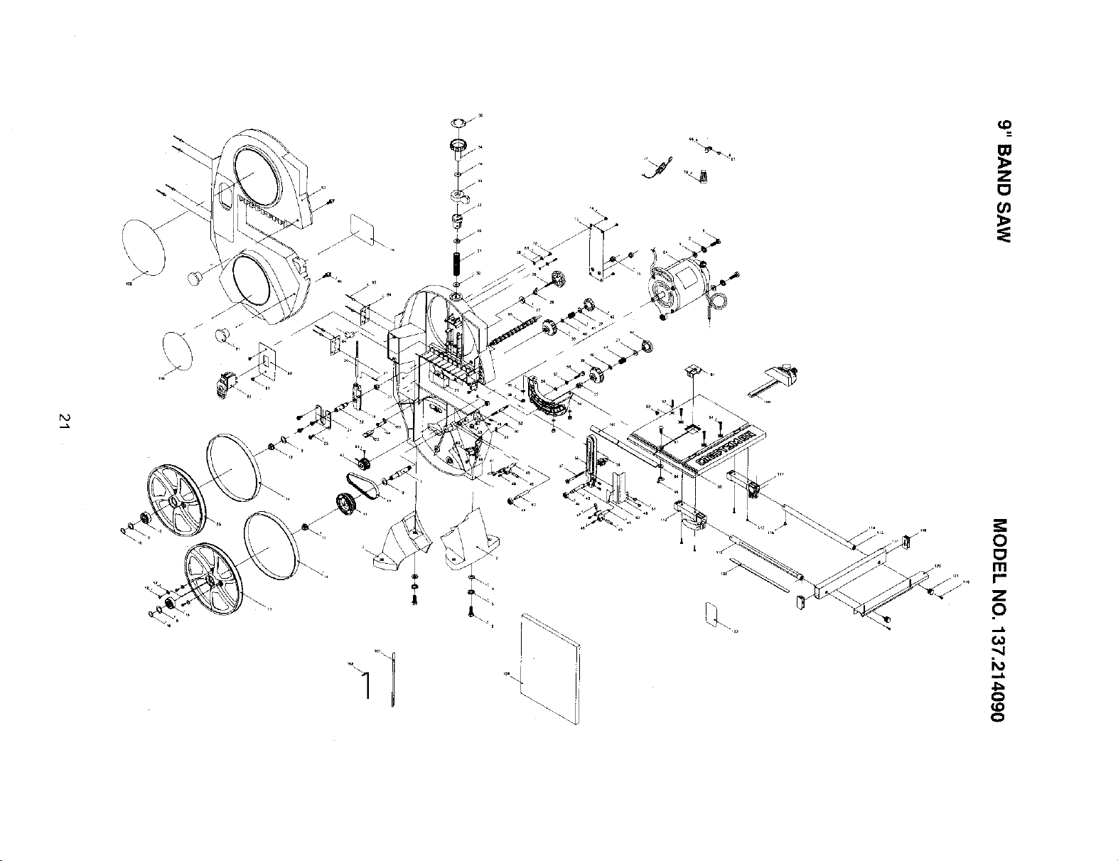
CRAFTSMAN 9" BAND SAW
MODEL NO. 137.214090
FqiArr/_=
When servicing use only CRAFTSMAN replacement parts. Use of any other parts many create a HAZARD or cause
product damage.
p'_r=r/,.1=q#I1_[-=:
Any attempt to repair or replace electrical parts on this Band Saw may create a HAZARD unless repair is clone by a
qualified service technician. Repair service is available at your nearest Sears Service Center,
Always order by PART Number, not by key number.
K_ Pad NO Description Qty Key Part No Descdp_on
300200101 MAIN BODY 1 66 300206601 CLIP
2 300200201 BASE _ 67 300206701 CR HS SCREW W/I WASHER 3/16"×1/4"
3 300200301 BASE 1 68 30020680f TOOTH WASHER
4 300200401 FLAT WASHER 3/8 ¸' X 192 4 69 300206901 COPPER WASHER
5 300200501 SPRING WASHER 3/8" 4 70 300207001 CR HD SCREW W/I WASHER 3/16"X_/4 ¸'
6 300200601 HEX. SCREW 0/8" XI" 4 71 300207101 CON[)ENSER
7 300200701 SHAFT OF LOWER WHEEL 1 72 30020720f CR. He. SCREW W/I WASHER 3/16"Xl/4"
8 300200801 NYLON NUT 1 73 300207301 PLATE
9 300200901 WASHER 4 74 300207401 CR HD SCREW W/[ WASHER 3/16"X1/4"
10 300201001 P D BELT 25-130XL 1 75 300207501 STRAIt_RELIEFBUSH_NG
11 220221101 PULLEY 1 76 300207601 LABEL
12 300201201 POWDER COPPER 2 77 300207701 POWER LORD W/I PLUG
13 200201301 LOWERWHEEL 1 72 300207801 TERMINAL
14 30022f401 WHEELPROTECTOR 2 79 300207901 FLATWASHER
15 300221501 BALLBEARfNG 2 80 300208021 SWtTCHpLATE
16 300201601 C RING 2 81 302208101 CR HC SCREW W/IWASHER 3/16"X1/4"
17 300221701 FLATWASHER 3 82 300208201 SWITCH
12 300201801 SELF-TAPPED SCREW 3 83 300208301 COVER
12 300201901 SLIDINGHOLDER 1 84 300208401 HINGE
20 302202201 BOLT • 1 85 302208501 BLrND RIVET
2J 300202101 SPRING PIN 1 86 300208801 SeeING CLIPER
22 300222201 S}4AFF UPPER WHEEL 1 27 302222701 KNOB
23 300202301 NYLON NUT ! 28 300208201 SPRfNG PLATE
24 300202401 SLIDING PLATE 1 89 300208201 CR HI) SCREW W!IWASHER 3/12"!/4"
22 322202501 CR HC SCREW W/tWASHER 1/4" X 3/8" 4 90 300209001 TABLE
26 320202601 UP WHEEL 1 91 300202101 TABLE INSERT
27 320202701 FLATWASHER 1/4" X_6 0 92 300209221 SCREW 1/4"X3/4 ¸'
28 300202801 eUTTERELY NUT 1/4¸` 1 93 30020930_ HEX NUT 1/4"
29 320202901 STAR KNOB l 94 300209401 H0 SCREW 1/4"X1-1/4"
3() 3002O30O1 ELATWASHER 5/16X18-2 2 95 300209201 SPR_NGWASHER
31 30(3203101 SPRING 1 26 30O209601 HEX NUT 1/4"
32 300200201 OUICKADJSUTINGBRACKET 1 97 300209701 CARRIAGE SCREW M16X18
33 300203301 OUICKAeJSUTINGBUTTON 1 98 300209801 ELATWASHER MSX14X1
34 320200401 TtJRNNJNGKNOB 1 92 300209901 BUTTERFLYNUT M6
35 300203501 TURNNfNG BUTTON COVER 1 100 300210001 MITERGAUGEASSEMBLY
36 300203601 ADJUSTGU[DE ! 101 300210101 WARNING LABEL
37 300203701 CARRIAGE S_REW 1 102 300210201 PLASTIC BRUSH
38 302203801 TEETHGUIDEBOLT _ 103 300210301 BLADEGUARD
39 302203201 TRUNNING 8LiTtON 2 104 300210401 CR. HD. SCREW W/f WASHER
40 300204O01 FLATWASHER 1/4'X!2-1 2 105 3002_.0501 LABEL
41 3O0204101 SPRING 2 106 30O210601 WARNING LABEL
42 300204201 KNOB 2 !07 300210701 BLADE
43 300204301 BEARING SHAFT 2 108 300210801 HEX WRENCH
44 300204401 BALL BEARING 626ZZ 2 109 300210901 INSTRUCTION MANUAL
45 300204501 YTYPEBLOCK 2 fl0 300211001 SIDEBASEWITHCLAMPHANDL£
48 300204601 KEY 5X5XEE 2 111 300211101 SIDEBASE(LEFT)
47 300204701 KEY 5X5X25 2 1!2 300211201 CR RE HD SCREW M6-10
48 320204801 SCREW 1/41X3/8 ' 8 113 300211301 NUT
49 322204901 BLADEGUARD 1 114 300211401 LEFTTUBE
5_) ¸302205001 WARNINGSTICKET 1 115 3002t1501 RtGHTTUBE
51 302205101 CR HD SCREW 3,'16"xll4 '¸ 2 118 300211621 CR RE H0 SCREW 3/16"X1/4"
52 300202201 TRUNNtON FIXTURE BOLT 1 117 200211701 EXTENSIONWlNG
53 300205301 WASHERNUT 1/4" 2 118 200211801 SIDECOVEF_
54 300205401 TABLE BRACKET 1 _!9 000211901 HEX SCREW
55 322205501 TEETH GUJDE BOLT 1 120 000212001 RIP FENCE
58 3002(35601 NYLONWASHER 1 121 300212101 KNeE
57 30(7205721 WAVEWASHER 1 122 300212201 SCALE
58 300205221 SETSCREW 1 _23 300212301 LABEL
59 3002052O1 POINTER 124 200212401 LABEL
§O 3002O6001 CR HS SCREWW/tWASHER 3/16"×1/4 _ 125 300215001 LABEL
6_ 300206101 MOTOR 1
62 300228201 PULLEY 1
63 300206301 SCREW MAX! OL 2
64 300206401 90 CONNECTOR 1
65 300206501 BLOWER 1
...... __ i_- ....... _ 20 .... I1! IIIII III RIIll
r_3
(D
Z
t_
I-
0
(D
0

Your Home
For repair-in your home-of all major brand appliances,
lawn and garden equipment, or heating and cooling systems,
no matter who made it, no matter who sold it!
For the replacement parts, accessories and
Operator's Manuals that you need to do-it-yourself.
For Sears professional installation of home appliances
and items like garage door openers and water heaters.
1-800-4-MY-HOME ® (1-800.469-4663)
Call anytime, day or night (U.S.A. and Canada)
www,sears.com www.sears.ca
Our Home
For repair of carry-in items like vacuums, lawn equipment,
and electronics, call or go on-line for the location of your nearest
Sears Parts & Repair Center.
1-800-488-1222
Call anytime, day or night (U.S.A. only)
www.sears.com
To purchase a protection agreement on a product serviced by Sears:
1-800-827-6655 (U.S.A.) 1-800-361-6665 (Canada)
Para pedir servicio de reparaci6n Au Canada pour service en fran£ais:
a domicilio, y para ordenar piezas: 1-800-LE-FOYER Mc
1-888-SU-HOGAR s_ (1-800-533-6937)
(1-888-784-6427) www.sears.ca
SeARS-,,-,,,,J
® Registered Trademark / TMTrademark / SMService Mark of Sears. Roebuck and Go.
® Marea Regist rada / ,M Marca de F_brica / su Marea de Servicio de Sears. Roebuck and Co.
MCMarque de commerce / MDMarqUe depos_e de Sears, Roebuck and Co. © Sears. Roebuck and Co.