
Operator's Manual
CRAFTSMAN ++
_ PROFESSI ONAL_
18"
Metal Cutting
BAND SAW WITH WELDER
Model No.
351.21 4300
CAUTION: Read and follow
all Safety Rules and Operating
Instructions before First Use
of this Product.
Sears, Roebuck and Co., Hoffman Estates, IL 60179 U.S.A.
www.sears.com/craftsman
25173.01 Draft (05/21/07)
Warranty.................................... 2
SafetyRules............................... 2-3
Unpacking.................................. 3
Assembly................................... 3
Installation................................. 3-5
Operation................................ 5-11
Maintenance................................ 11
Troubleshooting........................... 12-13
PartsIllustrationsandLists.................. 14-23
BE PREPARED FOR JOB
• Wear proper apparel. Do not wear loose clothing,
gloves, neckties, rings, bracelets or other jewelry
which may get caught in moving parts of machine.
• Wear protective hair covering to contain long hair.
• Wear safety shoes with non-slip soles.
• Wear safety glasses complying with United States
ANSI Z87.1. Everyday glasses have only impact
resistant lenses. They are NOT safety glasses.
• Wear face mask or dust mask if operation is dusty.
• Be alert and think clearly. Never operate power tools
when tired, intoxicated or when taking medications
that cause drowsiness.
ONE-YEAR FULL WARRANTY ON
CRAFTSMAN PROFESSIONAL TOOL
If this Craftsman tool fails due to a defect in material or
workmanship within one year from the date of purchase,
call 1-800-4-MY-HOME® TO ARRANGE FOR FREE
REPAIR (or replacement if repair proves impossible).
This warranty does not include expendable parts, such
as lamps, batteries, bits or blades.
If this tool is ever used for commercial or rental purposes,
this warranty will apply for only 90 days from the date
of purchase.
This warranty gives you specific legal rights and you may
also have other rights which vary from state to state.
Sears, Roebuck and Co., Hoffman Estates, IL 60179
WARNING: Some dust created by power sanding,
sawing, grinding, drilling and other construction activi-
ties contains chemicals known to cause cancer, birth
defects or other reproductive harm.
Some examples of these chemicals are:
• Lead from lead-based paints.
• Crystalline silica from bricks and cement and other
masonry products.
• Arsenic and chromium from chemically-treated lumber.
Your risk from these exposures vary, depending on how
often you do this type of work. To reduce your exposure
to these chemicals: work in a well ventilated area and
work with approved safety equipment. Always wear
OSHA/NIOSH approved, properly fitting face mask
or respirator when using such tools.
WARNING: For your own safety, read all of the
instructions and precautions before operating tool.
CAUTION: Always follow proper operating procedures
as defined in this manual -- even if you are familiar
with use of this or similar tools. Remember that being
careless for even a fraction of a second can result in
severe personal injury.
PREPARE WORK AREA FOR JOB
• Keep work area clean. Cluttered work areas invite
accidents.
• Do not use power tools in dangerous environments.
Do not use power tools in damp or wet locations.
Do not expose power tools to rain.
• Work area should be properly lighted.
• Proper electrical receptacle should be available for
tool. Three-prong plug should be plugged directly
into properly grounded, three-prong receptacle.
• Extension cords should have a grounding prong and
the three wires of the extension cord should be of
the correct gauge.
• Keep visitors at a safe distance from work area.
• Keep children out of workplace. Make workshop
childproof. Use padlocks, master switches or remove
switch keys to prevent any unintentional use of
power tools.
TOOL SHOULD BE MAINTAINED
• Always unplug tool prior to inspection.
• Consult manual for specific maintaining and adjust-
ing procedures.
• Keep tool lubricated and clean for safest operation.
• Remove adjusting tools. Form habit of checking to
see that adjusting tools are removed before switch-
ing machine on.
• Keep all parts in working order. Check to determine
that the guard or other parts will operate properly
and perform their intended function.
• Check for damaged parts. Check for alignment of
moving parts, binding, breakage, mounting and any
other condition that may affect a tool's operation.
• A guard or other part that is damaged should
be properly repaired or replaced. Do not perform
makeshift repairs. (Use parts list provided to order
replacement parts.)
KNOW HOW TO USE TOOL
• Use right tool for job. Do not force tool or attachment
to do a job for which it was not designed.
• Disconnect tool when changing blade.
© Sears, Roebuck and Co. 2
• Avoid accidental start-up. Make sure that the tool is
in the "off" position before plugging in.
• Do not force tool. It will work most efficiently at the
rate for which it was designed.
• Keep hands away from moving parts and cutting
surfaces.
• Never leave tool running unattended. Turn the
power off and do not leave tool until it comes to
a complete stop.
• Do not overreach. Keep proper footing and balance.
• Never stand on tool. Serious injury could occur if tool
is tipped or if blade is unintentionally contacted.
• Know your tool. Learn the tool's operation, applica-
tion and specific limitations.
• Use recommended accessories (refer to page 17).
Use of improper accessories may cause risk of
injury to persons.
• Handle workpiece correctly. Protect hands from
possible injury.
• Turn machine off if it jams. Blade jams when it digs
too deeply into workpiece. (Motor force keeps it
stuck in the work.) Do not remove summed or cut
off pieces until the saw is turned off, unplugged
and the blade has stopped.
WARNING: The operation of any power tool can result
in foreign objects being thrown into the eyes, which can
result in severe eye damage. Always wear safety goggles
complying with United States ANSI Z87.1 (shown on
package) before commencing power tool operation.
Safety goggles are available through your Sears catalog.
WARNING: Be careful not to touch overhead power
lines, piping, lighting, etc., if lifting equipment is used.
Band saw weighs approximately 1000 Ibs. Proper tools,
equipment and qualified personnel should be employed
in all phases of unpacking and installation.
IMPORTANT: Table is coated with a protectant. To
ensure proper fit and operation, remove coating.
Coating is easily removed with mild solvents, such as
mineral spirits, and a soft cloth. Avoid getting solution
on paint or any of the rubber or plastic parts. Solvents
may deteriorate these finishes. Use soap and water
on paint, plastic or rubber components. After cleaning,
cover all exposed surfaces with a light coating of oil.
Paste wax is recommended for table top.
WARNING: Never use highly volatile solvents. Non
flammable solvents are recommended to avoid possible
fire hazard.
Refer to Figure 16.
CAUTION: Do not attempt assembly if parts are miss-
ing. Use operator's manual to order replacement parts.
MOUNT RIP FENCE
Refer to Figure 16.
Thread rip fence lock knob into rip fence (Key Nos. 43
and 42) and slide rip fence into groove on top of work
table. Secure rip fence with lock knob.
Refer to Figures 2-5, 14 and 17.
Check for shipping damage. If damage has occurred,
a claim must be filed with carrier. Check for complete-
ness. Immediately report missing parts to dealer.
The band saw comes assembled as one unit. Additional
parts which need to be fastened to the saw should be
located and accounted for before assembling:
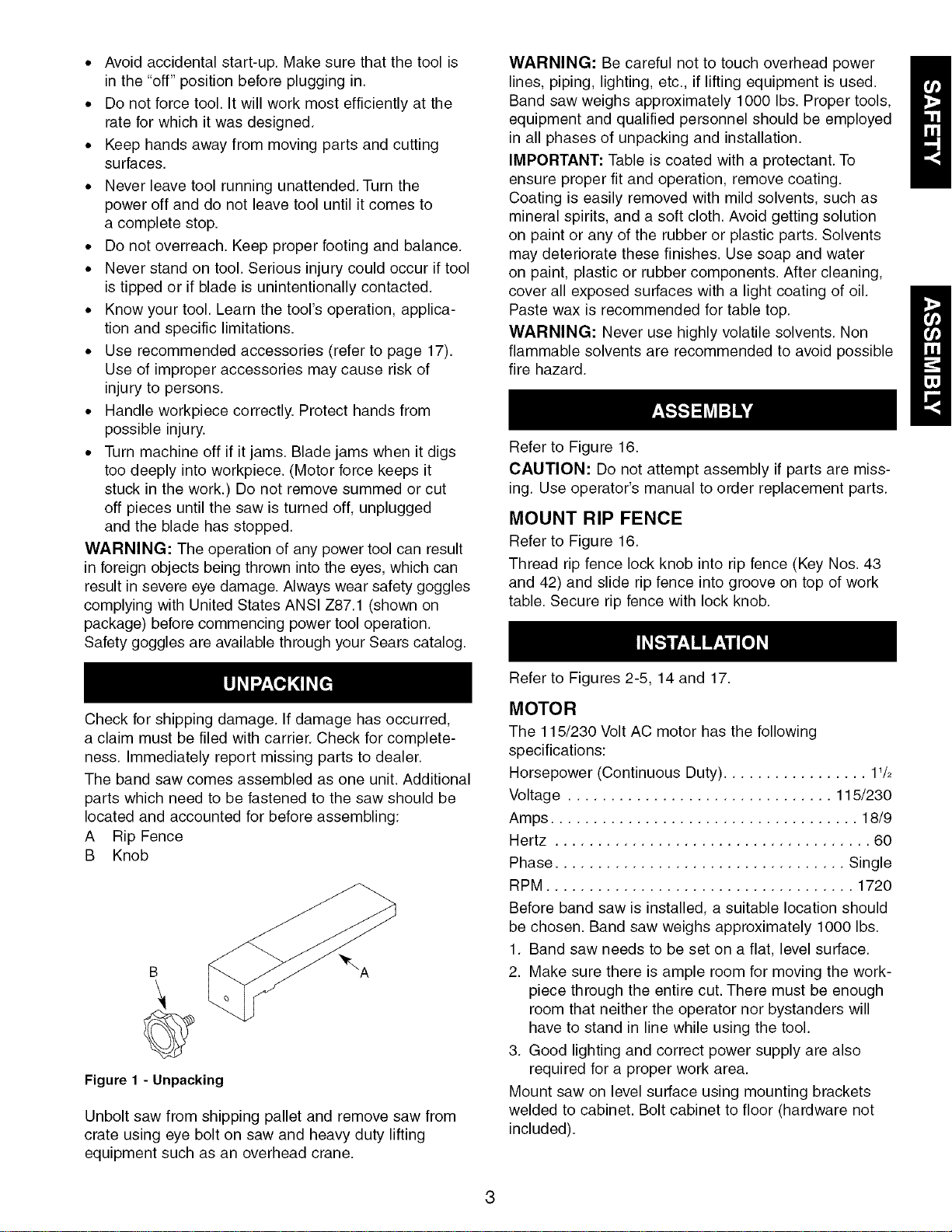
A Rip Fence
B Knob
B
Figure 1 - Unpacking
Unbolt saw from shipping pallet and remove saw from
crate using eye bolt on saw and heavy duty lifting
equipment such as an overhead crane.
MOTOR
The 115/230 Volt AC motor has the following
specifications:
Horsepower (Continuous Duty) ................. 11/2
Voltage ............................... 115/230
Amps .................................... 18/9
Hertz ..................................... 60
Phase .................................. Single
RPM .................................... 1720
Before band saw is installed, a suitable location should
be chosen. Band saw weighs approximately 1000 Ibs.
1. Band saw needs to be set on a flat, level surface.
2. Make sure there is ample room for moving the work-
piece through the entire cut. There must be enough
room that neither the operator nor bystanders will
have to stand in line while using the tool.
3. Good lighting and correct power supply are also
required for a proper work area.
Mount saw on level surface using mounting brackets
welded to cabinet. Bolt cabinet to floor (hardware not
included).
POWER SOURCE
Band saw requires a 115 or 230 volt, 60 Hz power
source. Band saw is shipped with motor and controls
prewired for 115 volt operation. Line cord does not
have plug. A 115 volt, 20/30A three-prong plug must
be attached to the line cord.
The motor is designed for operation on the voltage and
frequency specified. Normal loads will be handled safe-
ly on voltages not more than 10% above or below the
specified voltage.
Running the unit on voltages which are not within
the range may cause overheating and motor burn-out.
Heavy loads require that the voltage at motor terminals
be no less than the voltage specified. Power supply to
the motor is controlled by a double pole locking rocker
switch. Remove the key to prevent unauthoriFed use.
GROUNDING INSTRUCTIONS
WARNING: Improper connection of equipment
grounding conductor can result in the risk of electrical
shock. Equipment should be grounded while in use to
protect operator from electrical shock.
Check with a qualified electrician if grounding instruc-
tions are not understood or if in doubt as to whether
the tool is properly grounded.
Green (or green and yellow) conductor in cord is the
grounding wire. If repair or replacement of the electric
cord or plug is necessary, do not connect the green
(or green and yellow) wire to a live terminal.
Many cover plate screws, water pipes and outlet boxes
are not properly grounded. To ensure proper ground,
grounding means must be tested by a qualified
electrician.
To use the band saw with a 230V power supply:
WARNING: All electrical connections must be
performed by a qualified electrician.
• Have a qualified electrician attach a 230 volt,
20/30A 3-prong plug band saw line cord.
• Open cover (Figure 17, Key No. 8) by removing
eight pan head screws.
• Change wire from 115V terminal of transformer
to the unused 230V terminal (See Figure 2).
• Change amperage setting on the thermal overload
relay (See Figure 2).
• Replace cover.
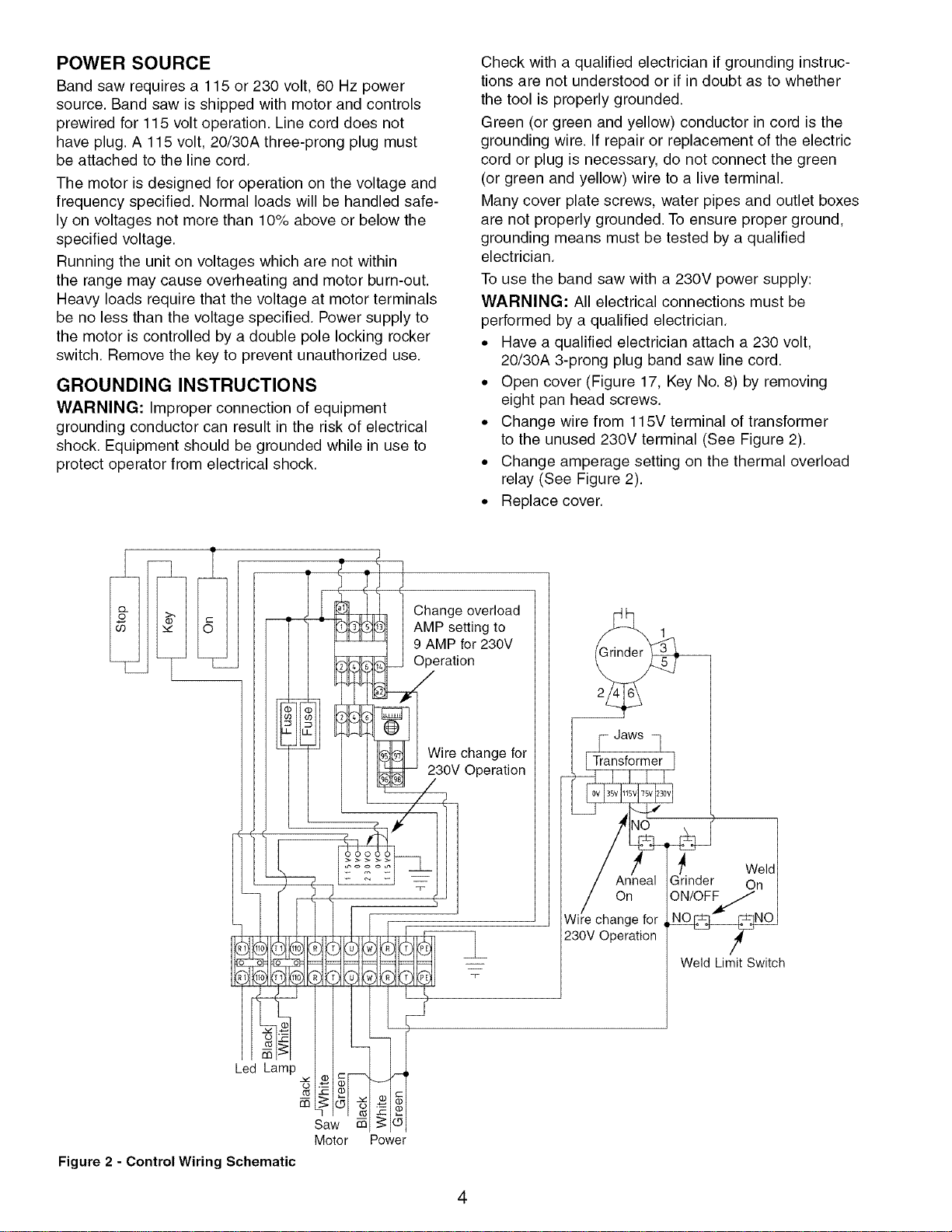
Change overload
AMP setting to
9 AMP for 230V
Operation
Wire change for
230V Operation
On
Wir/e change for
230V Operation
Weld Limit Switch
Led Lamp
Saw co
Motor Power
Figure 2 - ControlWiring Schematic
4
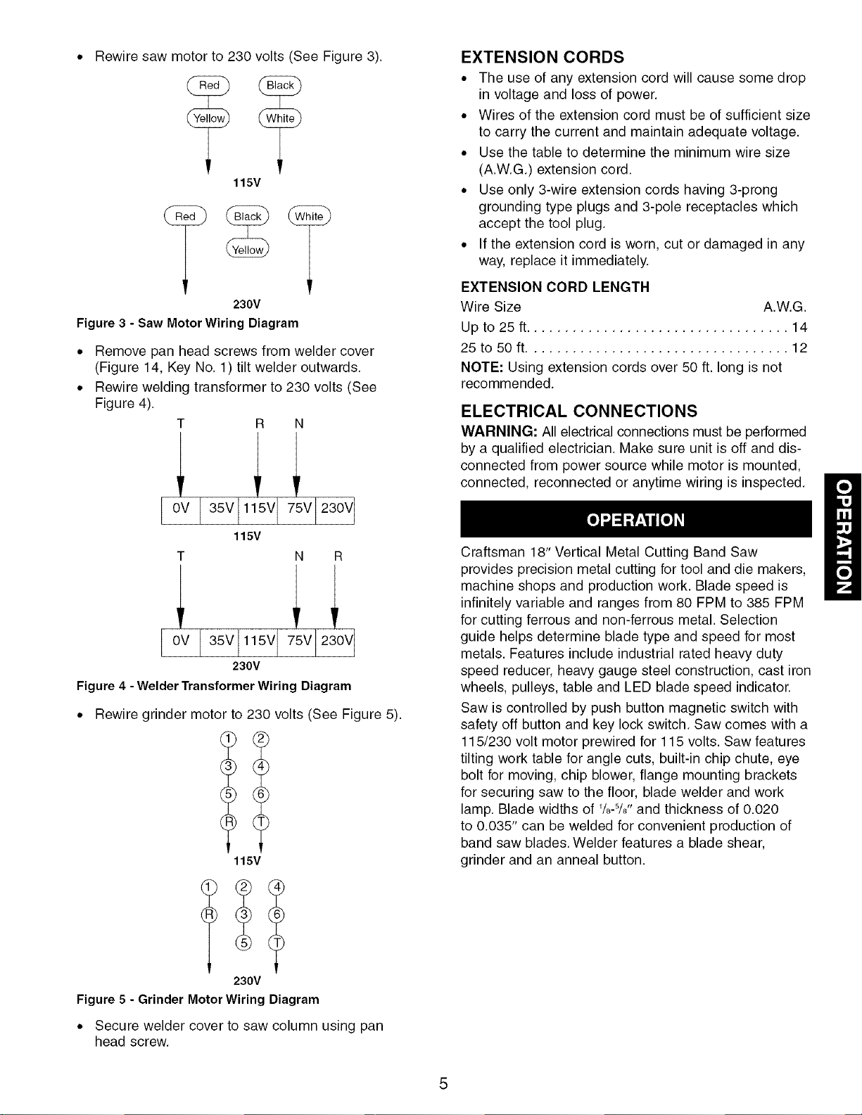
Rewire saw motor to 230 volts (See Figure 3).
115V
230V
Figure 3 - Saw Motor Wiring Diagram
• Remove pan head screws from welder cover
(Figure 14, Key No. 1) tilt welder outwards.
• Rewire welding transformer to 230 volts (See
Figure 4).
R N
Cv 35V 1 V V 230V
115V
N R
C 35V 115V V 2 V
230V
Figure 4 - WelderTransformerWiring Diagram
• Rewire grinder motor to 230 volts (See Figure 5).
115V
230V
Figure 5 - Grinder Motor Wiring Diagram
• Secure welder cover to saw column using pan
head screw.
EXTENSION CORDS
• The use of any extension cord will cause some drop
in voltage and loss of power.
• Wires of the extension cord must be of sufficient size
to carry the current and maintain adequate voltage.
• Use the table to determine the minimum wire size
(A.W.G.) extension cord.
• Use only 3-wire extension cords having 3-prong
grounding type plugs and 3-pole receptacles which
accept the tool plug.
• If the extension cord is worn, cut or damaged in any
way, replace it immediately.
EXTENSION CORD LENGTH
Wire Size A.W.G.
Up to 25 ft.................................. 14
25 to 50 ft.................................. 12
NOTE: Using extension cords over 50 ft. long is not
recommended.
ELECTRICAL CONNECTIONS
WARNING: All electrical connections must be performed
by a qualified electrician. Make sure unit is off and dis-
connected from power source while motor is mounted,
connected, reconnected or anytime wiring is inspected.
Craftsman 18" Vertical Metal Cutting Band Saw
provides precision metal cutting for tool and die makers,
machine shops and production work. Blade speed is
infinitely variable and ranges from 80 FPM to 385 FPM
for cutting ferrous and non-ferrous metal. Selection
guide helps determine blade type and speed for most
metals. Features include industrial rated heavy duty
speed reducer, heavy gauge steel construction, cast iron
wheels, pulleys, table and LED blade speed indicator.
Saw is controlled by push button magnetic switch with
safety off button and key lock switch. Saw comes with a
115/230 volt motor prewired for 115 volts. Saw features
tilting work table for angle cuts, built-in chip chute, eye
bolt for moving, chip blower, flange mounting brackets
for securing saw to the floor, blade welder and work
lamp. Blade widths of '/8-5/8'' and thickness of 0.020
to 0.035" can be welded for convenient production of
band saw blades. Welder features a blade shear,
grinder and an anneal button.
SPECIFICATIONS
Depth of throat ............................. 18"
Maximum depth of cut ...................... 10s/4''
Table size ........................... 23% x 21%"
Table tilt ............................ -15 to +15 °
Wheel diameter ............................ 18"
Blade length .............................. 140"
Blade width ............................. 1/8to %"
Blade speeds .... infinitely variable from 80 to 385 FPM
Overall dimensions .................. 75 x 37 x 30"
Shipping weight ........................ 1012 Ibs
Dust collection port ........................... 4"
CAUTION: Always observe the following safety
precautions:
• Make sure that blade guides and thrust bearings are
positioned and adjusted correctly to prevent side-
ways and rearward movement of the blade. Adjust
upper guide to just clear workpiece.
• Check to make sure blade is tensioned and tracking
properly. Do not over tension the blade in order to
prevent premature blade wear and breakage. Avoid
under tensioning to eliminate back and forth, side to
side blade movement as it cuts.
• Use proper blade and speed for the cutting operation.
• After turning saw on, allow blade to come to full
speed before attempting any cutting operation.
• Support workpiece properly and use a smooth
steady feed to guide work through the cut. Use
push sticks or push blocks when required.
• Keep hands away and out of line with moving parts.
• Always wear eye protection.
OPERATING SAW CONTROLS
Refer to Figures 6 and 7.
Band saw control panel has three functional operations:
ON - Green color push button that energizes the
magnetic contactor to start the band saw.
OFF - Red color push button that deenergizes the
magnetic contactor to stop the band saw. To restart the
saw, turn the knob to reset and depress the ON button.
KEY - Key switch locks machine to prevent
unauthorized use.
Key
Off On
÷
Figure 6 - Band Saw Control
The control panel for the blade welder is shown in
Figure 7. The welding circuitry is energized independent
of the band saw circuitry. To operate the welder, plug in
the line cord to a proper power source.
CAUTION: Do not operate the band saw and the
welder at the same time.
Anneal Button
Weld Button --
Movable Jaw --
Grinder Switch -
cTD,
@
Figure 7 - BladeWelder Control
@
Weld Pressure
-- Adjustment
Knob
Stationary
Jaw
....Jaw Clamping
Handles
REMOVING BLADE
Refer to Figures 15 and 16.
WARNING: Disconnect band saw from power source
when changing or adjusting blades. Wear leather gloves
when handling band saw blades. Never wear gloves
when operating saw.
• Turn handwheel (Figure 15, Key No. 38) counter-
clockwise. This lowers the idler wheel (Figure 15,
Key No. 5) and relieves tension in blade.
• Remove blade guard (Figure 16, Key No. 39) by
loosening screws (Figure 16, Key No. 49).
• Pull handle (Figure 15, Key No. 69) to open upper
and lower doors (Figure 15, Key Nos. 36 and 67).
• Be careful, blade may spring from saw.
• Remove blade from wheels and guide it out
through table slot.
INSTALLING BLADE
• Although many of the adjustments may not be altered
when blade is removed, every adjustment should be
checked prior to using a newly installed blade.
• Follow safety precautions every time saw is operated.
• Make sure blade teeth are pointing down towards
table. Turn blade inside out if necessary.
• Slip new blade into table slot and over upper and lower
blade wheels and center blade on blade wheels. Slide
blade in between blade guides. Replace table stud.
Replace blade guards after blade guide adjustment.
• Tension and track blade as described in the following
sections.
6
TENSIONING BLADE
Refer to Figure 15.
• Tension blade by rotating handwheel (Key No. 38). Be
sure blade guides do not interfere with blade path.
• Tighten blade until it is properly tensioned.
• A properly tensioned blade will ring slightly when back
of blade is plucked (like a string on an instrument).
NOTE: Check tension of new blade. Additional tension
may be required after a few minutes of operation.
TRACKING BLADE
Refer to Figure 15.
• Track blade after it has been tensioned. A change
in blade tension will affect wheel alignment. Proper
tracking is achieved when upper and lower wheels
are aligned.
• Set screws (Key No. 23) are used to align the track-
ing bracket to the saw frame.
• Turn idler wheel (Key No. 5) by hand and observe
how blade rides on the wheels.
• If blade rides away from the cabinet, tilt wheel up by
turning knob (Key No. 30) clockwise.
• If blade rides into cabinet, tilt wheel down by turning
knob counterclockwise.
ADJUSTING BLADE GUIDES
Refer to Figures 8 and 16.
NOTE: Adjust blade guides only after blade has been
properly tensioned and tracked.
• Blade guides support blade at sides and rear of
blade, and prevent twisting or deflection.
• Upper blade guides employ guide blocks for side
support and a grooved bracket at rear.
• Blade guide bracket (Key No. 20) should be posi-
tioned so guide blocks (Key No. 21) on either side
of blade will support as much of blade width as
possible without interfering with the tooth set.
• Adjust guide bracket depth by loosening set screw
(Key No. 40) and sliding bracket into position. Secure
position of bracket by tightening set screw.
• Loosen bolts (Key No. 24) and adjust guide blocks
(Key No. 21 ) to sides of blade. Use a feeler gauge to
check that guide blocks are 0.002" away from blade.
• Lock adjustment by tightening bolts.
• Adjust the height of upper guide assembly to clear
the workpiece by 1/4".Loosen locking knob (Key
No. 30) and use handle (Key Nos. 37 and 38) to
slide guide bar down until the upper guide assembly
clears workpiece by 1/4".Tighten locking knob.
• Lower blade guides employ two guide blocks for side
support. Lower guide bracket is spaced close to table
surface to minimize unsupported length of blade.
NOTE: Lower blade guard (Key No. 56) must be
removed to adjust lower blade guides.
• Loosen bolts (Key No. 26) to adjust lower guide
bracket (Key No. 19) so guide blocks do not interfere
with blade set. Loosen socket head bolts (Key No. 24)
for guide blocks (Key No. 21) and adjust guide blocks
to 0.002" from each side of blade.
0.002"
0.002"
Blade
Guide
Blade
Figure 8 - Blade Guide Adjustment
NOTE: 0.002" gap between blade and both blade
guides.
BLADE SPEED AND TYPE SELECTION
Refer to Blade Speed Chart.
• Consult Blade Speed Chart to determine blade
speed and blade type for required cutting operation.
Blades vary depending on type of material, size of
workpiece and type of cut that is being performed.
Characteristics which make blades different are
width, thickness, type of tooth and blade pitch.
• Width of blade describes distance from tip of a tooth
to back of blade. Width of blade will affect rigidity of
blade. A wider blade will wander less and produce
a straighter cut.
• Width of blade also limits the smallest radius which
can be cut. A 1/Z'wide blade can cut about a 1/2"
radius. Blade thickness describes the distance
between sides of blade. A thicker blade has more
rigidity and stronger teeth. A narrow thick blade
would be used to cut curves in piece while a wide
thin blade would be used to make long, straight cuts.
• Blade manufacturers are prepared to supply
information about blades for specific applications.
BLADE PITCH
Refer to Blade Speed Chart.
• Pitch describes number of teeth per inch. A blade
with more teeth per inch will produce a smoother
cut.
• Type of material being cut determines number of
teeth in contact with work.
• There should always be at least three teeth in con-
tact with workpiece to avoid shocking blade. Blade
shocking occurs when pitch is too large and blade
tooth encounters too much material. This can strip
teeth from blade.
• When pitch is too small the gullets of the teeth will
fill up, leading to the creation of excess heat.
MATERIAL
Highcarbonsteel
Freecuttingsteel
Ferro-manganese
Ferro-nickel
Ferro-nickel-chrome
Ferro-molybdenum
Ferro-chrome(med.)
Ferro-chrome(high)
Manganesesteel
Ferro-tungsten
Ferro-chrome-vanadium
Ferro-silicon-manganese
Machinerysteel
Ordinarytoolsteel
Highspeedsteel
Stainlesssteel
Thickironplate
Castiron
Nickelcastiron
Forgeablecastiron
Highgradecastiron
Coarsecastiron
Tombac
Bronze
Phosphorus-bronze
Nickelaluminumbronze
THICKNESS:
1/4"
230/18
200/18
200/18
165/18
130/24
150/18
165/18
100/24
180/18
150/18
165/18
150/18
180/18
130/24
100/24
130/18
165/18
200/18
200/18
200/18
150/18
200/18
1480/18
245/18
490/18
490/18
1/4-1"
200/14
150/14
156/14
130/14
100/18
130/14
100/14
75/14
150/14
100/14
100/14
130/14
130/14
100/18
75/14
100/14
130/12
200/14
150/12
165/14
130/14
165/14
1000/12
245/12
295/14
295/12
.3 tt
200/10
130/12
130/12
100/12
75/14
100/12
75/12
66/10
115/12
75/12
75/12
100/10
115/12
100/14
66/12
75/10
75/10
150/12
100/8
150/10
100/10
130/10
750/8
225/10
200/10
225/10
.6 tr
150/6
100/6
100/8
75/8
66/8
75/8
66/8
66/8
100/8
66/8
66/8
75/6
100/6
80/8
66/8
66/8
66/8
75/8
66/6
130/6
75/6
75/6
95/6
200/6
150/6
150/6
Magnesium-bronze
Hard aluminum
Aluminum
Copper
Fibers
Asbestos
295/18
2000/18
2000/18
395/18
1480/24
1300/24
245/12
2000/10
1650/10
295/12
1300/18
1000/18
225/10
2000/8
1300/6
245/8
1000/6
660/14
150/6
2000/6
820/4
150/6
750/4
490/10
6-1O"
150/4
100/4
100/4
75/4
66/6
75/6
66/6
66/6
66/4
66/4
66/4
75/4
66/4
75/4
66/4
66/4
66/4
75/4
66/4
130/4
66/4
75/4
295/4
150/4
150/4
150/4
150/4
1480/4
490/3
150/3
750/3
330/6
TYPE OF TOOTH
• The shape of teeth are varied to achieve specific
cutting results. A blade cuts work by removing
material. Blade teeth must scrape a chip of
workpiece away on each cut.
• The shape of gullet between teeth determines how
much material can be taken out with each blade
tooth.
• There should always be at least three teeth in con-
tact with workpiece to avoid shocking blade. Blade
shocking occurs when pitch is too large and blade
tooth encounters too much material. This can strip
teeth from blade.
• When pitch is too small, gullets of teeth will fill up
leading to creation of excess heat.
• Rake angle is the angle which the cutting face of
tooth makes with a line perpendicular to the back of
blade. A 0° rake angle is used to cut hard materials.
• Positive rake angle blades are used to cut softer
materials. Softer materials require more aggressive
chip removal.
• Larger gullets provide for faster removal but have to be
limited in size because they make blade teeth weaker.
• Blade teeth will also vary in the way that teeth have
been set from one side to the other. A wider set is
used for contour work because wider kerf allows
operator to cut tighter curves.
CHANGING BLADE SPEED
Refer to Figure 15.
WARNING: Never adjust blade speed unless machine
is running or damage to saw may result.
• Blade speed is adjusted by rotating handwheel (Key
No. 50) while machine is running. Rotate handwheel
clockwise to increase blade speed. Rotate hand-
wheel counterclockwise to decrease blade speed.
The blade speed is shown on LED display located
above switches.
8
ADJUSTING TABLE ANGLE
Refer to Figure 16.
Angle cuts can be made by tilting table left to right.
Loosen socket head bolts (Key No. 12) to tilt table up
to 15° right or left. Use angle scale to set table angle
(Key No. 18).
TYPE OF CUT
• Band saw can be used to perform a variety of cuts.
Cutting procedure used depends on size and
desired shape of cut.
• The rip fence is used to guide workpiece to produce
straight cuts on longer pieces.
• Contour cutting is done by guiding workpiece free-
hand to produce curved shapes.
• Beveled cutting can be done with any proper work
guide method by tilting table.
• Regardless of which method is used, a workpiece
which overhangs table by more than 10" should be
properly supported by free standing material stands.
See "Recommended Accessories," page 17.
USING RIP FENCE
Refer to Figure 16.
• Rip fence is used to guide workpiece straight into
blade producing a desired width of cut. Set rip fence
to desired width of cut on either side of blade. Kerr
of the blade must be considered when setting up.
• Lock rip fence securely with rip fence lock knob
(Key No. 43). The portion of material between blade
and rip fence is considered the workpiece. Material
outside of blade is considered scrap to be cut off.
• Guide workpiece into blade but do not push on scrap
side of material. Avoid passing hands beyond blade.
Use push sticks to finish cuts and pass workpiece
away from blade.
CONTOUR CUTTING
• When contour cutting, both hands must be used
to keep workpiece flat against table and guided
along path.
• Avoid placing hands in line of blade. If hands contact
blade it may cause injury.
• Stand in front of saw and use both hands over
portion of table to right of blade and before cut.
Do not attempt to cut sharp corners.
• Cut small corners by sawing around them and
removing scrap until shape is produced.
CHIP BLOWER
Refer to Figure 16.
• Band saw is equipped with chip blower used to
remove chips to make contour cutting easier.
• Adjust air nozzle (Key No. 31) so that pump air
blows chips away from blade and workpiece.
MITER GAUGE
• Use miter gauge (not provided) for securing and
holding workpiece at desired angle to produce
angled cuts. Use scale to adjust gauge to desired
angle.
• Never use miter gauge (not provided) and rip fence
at the same time. The blade might bind in the work-
piece. Operator could be injured and/or workpiece
could be damaged.
PREPARING BLADE FOR WELDING
• A properly prepared blade is essential in producing
a high-quality, long lasting band saw blade.
• The blade must be cut to proper length.
• Blade ends should be cut and ground square.
• Any rust, oil or dirt must be removed.
• Some teeth must be ground off blade ends depending
upon the pitch of the blade.
BLADE CUTTING
Refer to Figure 9.
• Cut the blade ends flat, square and smooth using
the blade shear.
• Lean the back of blade against the shear blade
guide when cutting blade ends (See Figure 9).
• Use grinder, as needed, to make blade ends flat,
square and smooth.
Butt Back of Blade
Against Shear
Figure 9 - Blade Cutting Alignment Surface
BLADE MOUNTING
Refer to Figure 10, page 10.
• Clean welder jaw of any scale, oil, rust or dirt. Clean
blade ends which contact welder jaws to provide
proper electrical contact.
• Set weld pressure adjustment knob to "0" (released).
• Insert one end of blade into stationary jaw with teeth
facing out and blade end centered between jaws.
• Firmly set back of blade against back alignment
surface of welder jaw and clamp blade tight with
the jaw clamping handle (See Figure 10, page 10).
• Insert other end of blade into movable jaw; butt the
blade ends together and clamp tight.
IMPORTANT: The blade ends should butt against each
other over the full width of the blade and should not
overlap (See Figure 10, page 10).
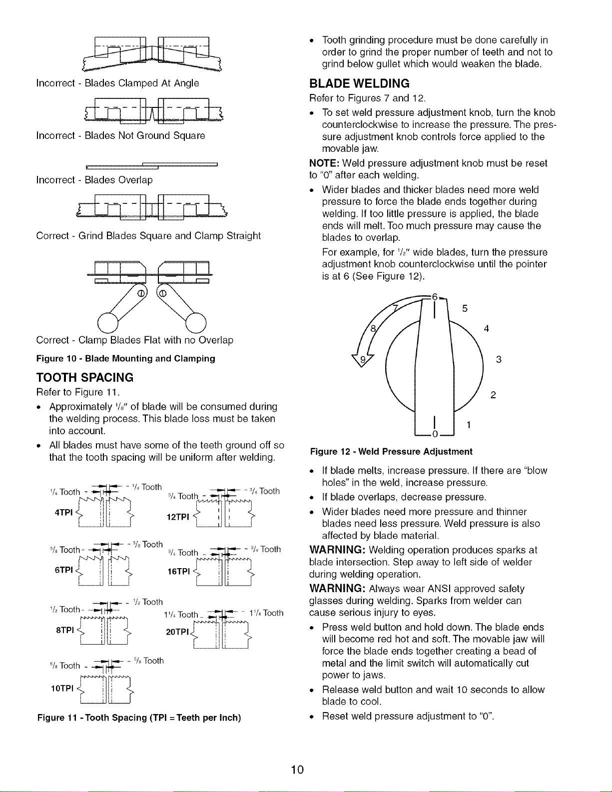
Incorrect- BladesClampedAtAngle
Incorrect - Blades Not Ground Square
Incorrect - Blades Overlap
Correct - Grind Blades Square and Clamp Straight
Correct - Clamp Blades Flat with no Overlap
Figure 10 - Blade Mounting and Clamping
TOOTH SPACING
Refer to Figure 11.
• Approximately 1/8"of blade will be consumed during
the welding process. This blade loss must be taken
into account.
• All blades must have some of the teeth ground off so
that the tooth spacing will be uniform after welding.
% Tooth _ - % Tooth
3. _ _ _ - 3/4Tooth
/4 Ioottl 7_1"t'j_P:-..
12TPI _
3/8Tooth - _ - 3/8Tooth 3/4Tooth - _ = 3/4Tooth
6TP,_ _ ,6TP, __
% Tooth = _ - _/2Tooth
1%Tooth__- 1%
8TP, __ 20TP,_ _
Figure 11 -Tooth Spacing (TPI = Teeth per Inch)
Tooth
• Tooth grinding procedure must be done carefully in
order to grind the proper number of teeth and not to
grind below gullet which would weaken the blade.
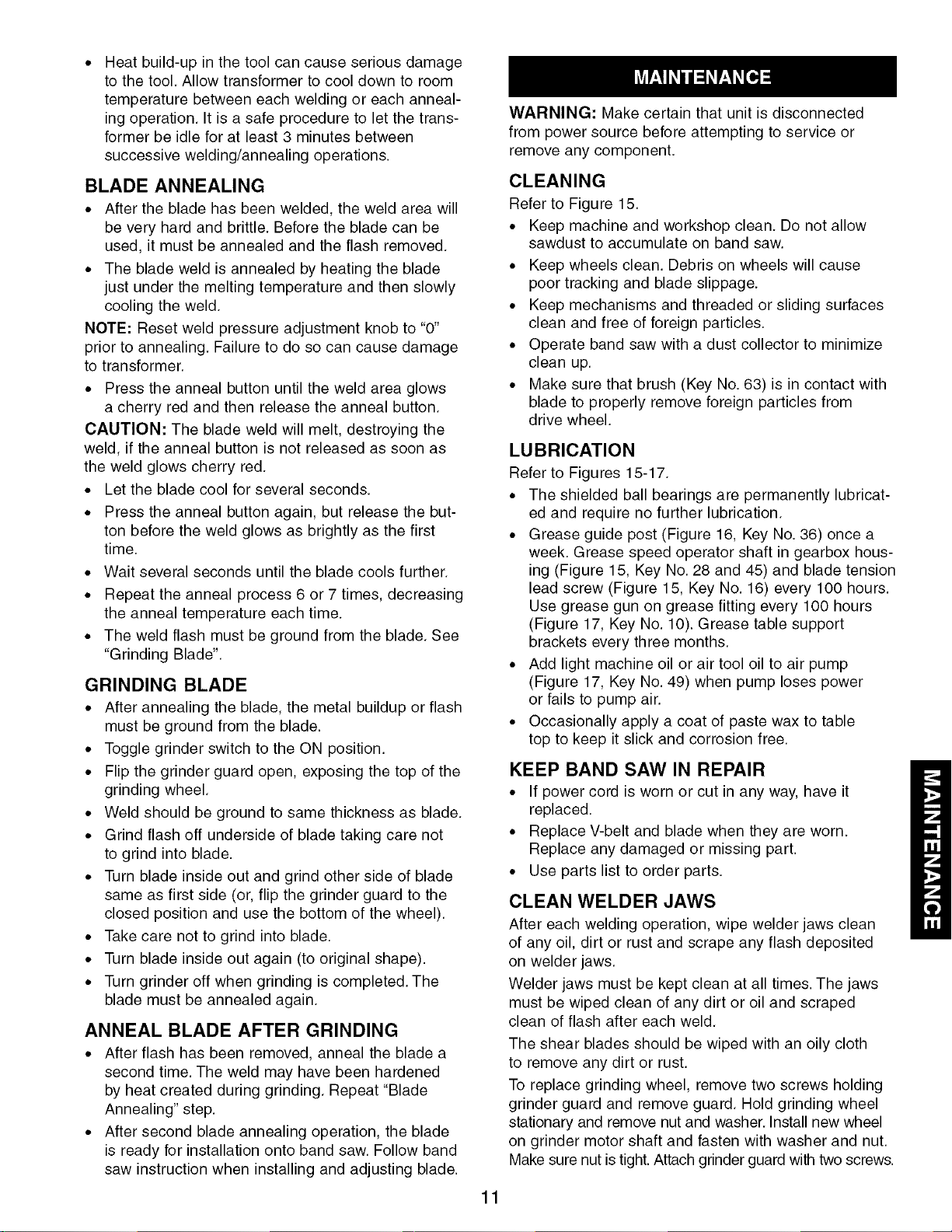
BLADE WELDING
Refer to Figures 7 and 12.
• To set weld pressure adjustment knob, turn the knob
counterclockwise to increase the pressure. The pres-
sure adjustment knob controls force applied to the
movable jaw.
NOTE: Weld pressure adjustment knob must be reset
to "0" after each welding.
• Wider blades and thicker blades need more weld
pressure to force the blade ends together during
welding. If too little pressure is applied, the blade
ends will melt. Too much pressure may cause the
blades to overlap.
For example, for 1/2"wide blades, turn the pressure
adjustment knob counterclockwise until the pointer
is at 6 (See Figure 12).
5
4
3
2
1
Figure 12 - Weld Pressure Adjustment
• If blade melts, increase pressure. If there are "blow
holes" in the weld, increase pressure.
• If blade overlaps, decrease pressure.
• Wider blades need more pressure and thinner
blades need less pressure. Weld pressure is also
affected by blade material.
WARNING: Welding operation produces sparks at
blade intersection. Step away to left side of welder
during welding operation.
WARNING: Always wear ANSI approved safety
glasses during welding. Sparks from welder can
cause serious injury to eyes.
• Press weld button and hold down. The blade ends
will become red hot and soft. The movable jaw will
force the blade ends together creating a bead of
metal and the limit switch will automatically cut
power to jaws.
• Release weld button and wait 10 seconds to allow
blade to cool.
• Reset weld pressure adjustment to "0".
10
Heat build-up in the tool can cause serious damage
to the tool. Allow transformer to cool down to room
temperature between each welding or each anneal-
ing operation. It is a safe procedure to let the trans-
former be idle for at least 3 minutes between
successive welding/annealing operations.
BLADE ANNEALING
• After the blade has been welded, the weld area will
be very hard and brittle. Before the blade can be
used, it must be annealed and the flash removed.
• The blade weld is annealed by heating the blade
just under the melting temperature and then slowly
cooling the weld.
NOTE: Reset weld pressure adjustment knob to "0"
prior to annealing. Failure to do so can cause damage
to transformer.
• Press the anneal button until the weld area glows
a cherry red and then release the anneal button.
CAUTION: The blade weld will melt, destroying the
weld, if the anneal button is not released as soon as
the weld glows cherry red.
• Let the blade cool for several seconds.
• Press the anneal button again, but release the but-
ton before the weld glows as brightly as the first
time.
• Wait several seconds until the blade cools further.
• Repeat the anneal process 6 or 7 times, decreasing
the anneal temperature each time.
• The weld flash must be ground from the blade. See
"Grinding Blade".
GRINDING BLADE
• After annealing the blade, the metal buildup or flash
must be ground from the blade.
• Toggle grinder switch to the ON position.
• Flip the grinder guard open, exposing the top of the
grinding wheel.
• Weld should be ground to same thickness as blade.
• Grind flash off underside of blade taking care not
to grind into blade.
• Turn blade inside out and grind other side of blade
same as first side (or, flip the grinder guard to the
closed position and use the bottom of the wheel).
• Take care not to grind into blade.
• Turn blade inside out again (to original shape).
• Turn grinder off when grinding is completed. The
blade must be annealed again.
ANNEAL BLADE AFTER GRINDING
• After flash has been removed, anneal the blade a
second time. The weld may have been hardened
by heat created during grinding. Repeat "Blade
Annealing" step.
• After second blade annealing operation, the blade
is ready for installation onto band saw. Follow band
saw instruction when installing and adjusting blade.
WARNING: Make certain that unit is disconnected
from power source before attempting to service or
remove any component.
CLEANING
Refer to Figure 15.
• Keep machine and workshop clean. Do not allow
sawdust to accumulate on band saw.
• Keep wheels clean. Debris on wheels will cause
poor tracking and blade slippage.
• Keep mechanisms and threaded or sliding surfaces
clean and free of foreign particles.
• Operate band saw with a dust collector to minimize
clean up.
• Make sure that brush (Key No. 63) is in contact with
blade to properly remove foreign particles from
drive wheel.
LUBRICATION
Refer to Figures 15-17.
• The shielded ball bearings are permanently lubricat-
ed and require no further lubrication.
• Grease guide post (Figure 16, Key No. 36) once a
week. Grease speed operator shaft in gearbox hous-
ing (Figure 15, Key No. 28 and 45) and blade tension
lead screw (Figure 15, Key No. 16) every 100 hours.
Use grease gun on grease fitting every 100 hours
(Figure 17, Key No. 10). Grease table support
brackets every three months.
• Add light machine oil or air tool oil to air pump
(Figure 17, Key No. 49) when pump loses power
or fails to pump air.
• Occasionally apply a coat of paste wax to table
top to keep it slick and corrosion free.
KEEP BAND SAW IN REPAIR
• If power cord is worn or cut in any way, have it
replaced.
• Replace V-belt and blade when they are worn.
Replace any damaged or missing part.
• Use parts list to order parts.
CLEAN WELDER JAWS
After each welding operation, wipe welder jaws clean
of any oil, dirt or rust and scrape any flash deposited
on welder jaws.
Welder jaws must be kept clean at all times. The jaws
must be wiped clean of any dirt or oil and scraped
clean of flash after each weld.
The shear blades should be wiped with an oily cloth
to remove any dirt or rust.
To replace grinding wheel, remove two screws holding
grinder guard and remove guard. Hold grinding wheel
stationary and remove nut and washer. Install new wheel
on grinder motor shaft and fasten with washer and nut.
Make sure nut is tight. Attach grinder guard with two screws.
11

SYMPTOM
Excessive blade breakage
Premature blade dulling
Crooked cuts
POSSIBLE CAUSE(S)
1. Material not secure on table
2. Incorrect speed or feed
3. Blade too coarse for material
4. Incorrect blade tension
5.Teeth in contact with work before
sawing
6. Blade rubs on wheel flange
7. Misaligned guides
8. Blade too thick for wheel diameter
9. Cracking at weld
1. Blade too coarse
2. Excessive blade speed
3. Inadequate feed pressure
4. Hard spots or scale in or on
material
5.Work hardening of workpiece
6. Blade installed backwards
7,
1.
2.
3.
4.
5.
6.
7.
8.
Insufficient blade tension
Work not square
Rate of feed too great
Blade guides not adjusted properly
Insufficient blade tension
Upper blade guide too far
from workpiece
Dull blade
Incorrect speed
Blade guide assembly loose or
blade thrust bearing loose
Rough cuts 1.Too much speed or feed
2. Blade too coarse
Blade is twisting or unusual
wear on side/back of blade
Teeth ripping from blade
1.Cut is binding blade
2. Blade guides or bearing worn
3. Blade guides or bearings not
adjusted properly
4. Blade guide brackets loose
1.Teeth too coarse for work
2. Rate of feed too great
3. Vibrating workpiece
4. Teeth filling with material
CORRECTIVE ACTION
1. Squarely place work on table
2. Check Blade Speed (page 7)
3. Use finer pitch blade
4. Tension blade properly; see "Operation"
5. Place blade in contact with work after saw is
started and has reached full speed
6. Adjust wheel alignment properly
7. Adjust blade guides properly
8. Use thinner blade
9. Replace blade
1. Use finer tooth blade
2. Try lower speed
3. Gently increase pressure
4. Reduce speed; increase rate of feed for
scale and change blades for hard spots
5. Increase rate of feed
6. Remove blade, twist inside out and reinstall
blade
7. Tension blade properly; see "Operation"
1. Use rip fence; adjust tilt of table at 90° to
blade
2. Reduce rate of feed
3. Move both guide blocks within 0.002" from
blade (use gauge)
4. Tension blade properly; see "Operation"
5. Adjust upper guide to just clear workpiece
by W'
6. Replace blade
7. Check Blade Speed; see page 7 for
recommended speeds
8. Tighten blade thrust bearing within 0.002"
behind blade back
1. Reduce speed or feed
2. Replace with finer blade
1. Decrease feed pressure
2. Replace
3. Adjust blade guides; see "Operation"
4. Tighten properly
1. Use blade with finer teeth
2. Decrease feed rate
3. Hold workpiece firmly
4. Use blade with coarser teeth
12

SYMPTOM
Motor running too hot
Saw will not start
POSSIBLE CAUSE(S)
1. Blade tension too great
2. Blade too coarse for work
(typical when cutting pipe)
3. Blade too fine for work (typical
when cutting slick or soft material)
4. Excessive dirt and chips
1,
2.
3.
4,
5.
Speed difficult adjust 1.
2.
Blade does not heat
up when weld button
is pressed
Misaligned weld
1,
2.
3.
4.
5.
6,
1.
2.
3.
4,
Blade ends overlap
Incomplete weld
Weld breaks when used
Blade melts when welding
1.
2.
1.
2.
3.
4.
CORRECTIVE ACTION
1. Reduce tension on blade
2. Use blade with finer teeth
3. Use blade with coarser teeth
4,
Key switch not on 1.
Not plugged in 2.
Loose electrical connections 3.
Thermal overload relay tripped 4.
Fuse blown 5.
Motor not running 1.
Worn/Broken V-belt(s) 2.
No power to welder 1.
Weld pressure adjustment not reset 2.
Weld pressure adjustment set to "0" 3.
Blade or jaws dirty, rusty or oily 4.
Loose connection to weld switch, 5.
limit switch, transformer,
or welder jaws
Burnt transformer 6.
Dirt or scale on jaws or blades 1.
Blade ends not cut square 2.
Blade ends not correctly 3.
aligned when clamped in jaws
Worn jaws 4.
Improper weld pressure 1.
Blade ends aligned incorrectly 2.
Weld pressure adjusted incorrectly 1.
Improper clamping 2.
Defective limit switch 3.
Movable jaw sticking 4.
1. Weld not annealed correctly
2. Weld ground too thin
3. Incomplete weld
1. Weld pressure adjusted incorrectly
2. Inaccurate moveable jaw retraction
Clean thoroughly; vacuum motor and speed
change mechanism
Turn key to on
Plug into supply
Have qualified electrician check electrical
connections
Reset relay, see "Grounding Instructions"
Check and replace fuse
Turn saw on
Check/Replace V-belts for Repair Part,
See Figure 17.
Check power at receptacle
Adjust weld pressure properly
Adjust weld pressure properly
Clean blade and jaws
Check; tighten if necessary
Replace
Clean jaws and blades
Cut ends square
Clamp blades against jaw alignment surface
Replace
Reduce weld pressure
Align blades properly
See "Blade Welding"
See "Mounting Blade"
Replace
Clean and oil jaw dovetails on inside
of cabinet
3. Movable jaw sticking 3.
Brittle welds 1. Weld not annealed correctly 1. See "Blade Annealing"
2. Dirt, oil or flash on blade or jaws 2. Clean blade and jaws
1. See "Blade Annealing"
2. Grind weld to thickness of blade
3. See Incomplete Weld section (above)
1. Increase weld pressure
2. Allow sufficient time for tool to cool down;
see "Blade Welding"
Clean and oil jaw dovetails on inside
of cabinet
13
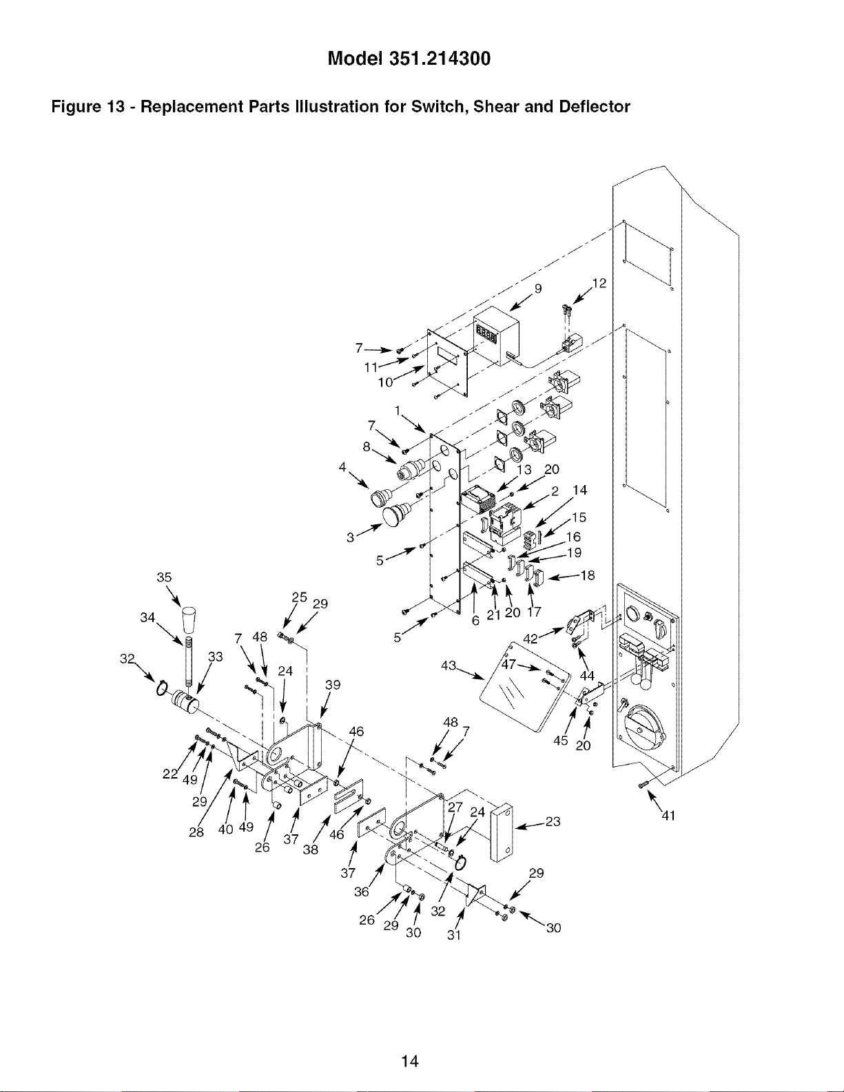
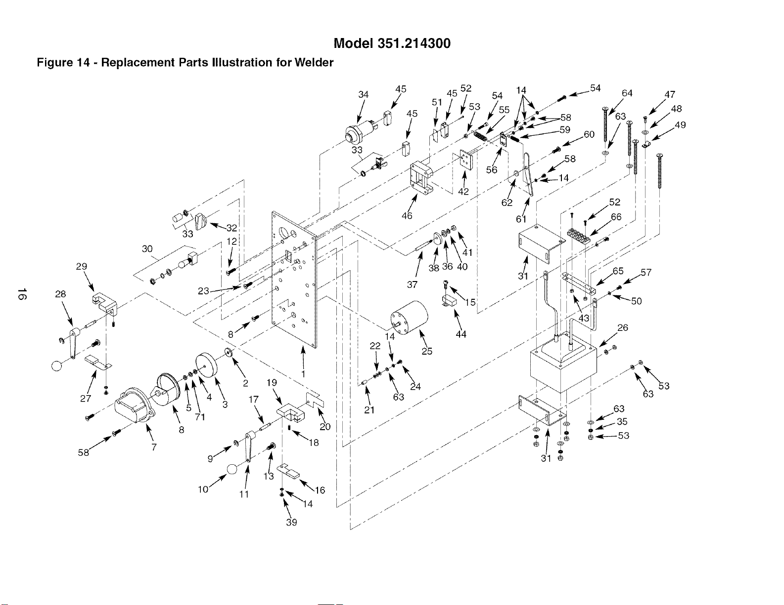
Model 351.21 4300
Figure 13 - Replacement Parts Illustration for Switch, Shear and Deflector
39
29
28
26 38
8_
4 13 20
14
46
?
37 29
\1
26 2i 30 31 "30
14
KEY
NO. PART NO.
1 20258.00
2 18637.00
3 17737.00
4 17738.00
5 STD863408
6 15561.00
7 STD863508
8 17739.00
9 16934.00
10 16935.00
11 17740.00
12 04493.00
13 18638.00
14 16760.00
15 16761.00
16 17400.00
17 17401.00
18 18006.00
19 17501.00
20 STD840409
21 05156.00
22 STD863635
23 20257.00
24 09845.00
DESCRIPTION
Switch Plate
Magnetic Starter
Stop Switch Assembly
Start Switch Assembly
4-0.7 x 8mm Pan Head Screw*
Bracket
5-0.8 x 8mm Pan Head Screw*
Key Switch with Two Keys
LED Readout with Sensor
Legend Plate
2.9-1.0 x 6mm Thread
Forming Screw
3-0.5 x 20mm Pan Head Screw
Transformer
Fuse Holder
Fuse
Stop Block
Terminal Block
Double Terminal Block
Ground Block
4-0.7mm Hex Nut*
4mm Serrated Washer
6-1.0 x 35mm Pan
Head Screw
Spacer
3CMI-6 E-ring
* Standard hardware item available locally.
QTY.
1
1
1
1
6
2
14
1
1
1
4
2
1
1
2
3
6
2
1
10
2
2
1
2
KEY
NO. PART NO. QTY.
25 STD870625 2
26
27
28
29
30
31
32
33
34
35
36
37
38
39
40
41
42
43
44
45
46
47
48
49
20260.00
20261.00
23928.00
STD851006
STD840610
23930.00
01900.00
05255.00
20262.00
17711.00
05252.00
20263.00
05254.00
05251.00
DESCRIPTION
6-1.0 x 25mm Socket
Head Bolt*
Spacer 4
Pin 1
Left Alignment Bracket 1
6mm Flat Washer* 7
6-1.0mm Hex Nut* 3
Right Alignment Bracket 1
3AMI-25 Retaining Ring 2
Blade Cam 1
Shear Handle 1
Knob 1
Right Bracket 1
Lower Blade 2
Upper Blade 1
Left Bracket 1
STD863640
05790.00
20267.00
20264.00
01316.00
20268.00
20266.00
STD863412
STD852005
STD852006
6-1.0 x 40mm Pan Head Screw* 1
6-1.0 x 15mm Pan Head Screw 6
Left Deflector Bracket 1
Spark Deflector 1
#10-32 x 5/16" Pan Head Screw 4
Right Deflector Bracket 1
Spacer 2
4-0.7 x 12mm Pan Head Screw 4
5mm Lock Washer* 4
6mm Lock Washer* 3
15
Model 351.21 4300
Figure 14 - Replacement Parts Illustration for Welder
30
71
11
39
14 _25 44
52
54
6
47
49
26
, 63
_,_---- 53
KEY
NO.
1
2
3
4
5
6
7
8
9
10
11
12
13
14
15
16
17
18
19
2O
21
22
23
24
25
26
27
28
29
30
31
32
33
PARTNO.
18640.00
20229.00
20230.00
STD851006
STD840610
20231.00
18641.00
05991.00
09845.00
09442.00
20232.00
01833.00
05790.00
STD852005
STD511002
05297.01
20234.00
00964.00
20235.00
05324.00
18642.00
04696.00
05318.00
05374.00
18643.00
18653.00
05330.01
20233.00
18644.00
18645.00
18652.00
20236.00
20237.00
DESCRIPTION
Welder Cover
Spacer
Grinding Wheel
6mm Flat Washer*
6-1.0mm Hex Nut*
Grinder Cover
Grinder Guard
#10-24 x 1/2" Flat Head Screw
3CMI-6 E-Ring
Knob
Right Clamping Lever
5-0.8 x 8mm Flat Head Screw
6-1.0 x 15mm Pan Head Screw
5mm Lock Washer*
#10-24 x 1/4" Pan Head Screw*
Right Clamp
Eccentric Shaft
6-1.0 x 6mm Set Screw
Stationary Jaw
Jaw Insulator
Insulating Tube
Insulating Washer
5-0.8 x 12mm Flat Head Screw
5-0.8 x 15mm Socket Head Bolt
Motor
Transformer
Left Clamp
Left Clamping Lever
Movable Jaw
Grinder Switch Assembly
Bracket
Pressure Adjustment Knob
Anneal Button Assembly
* Standard hardware item available locally.
2, Not Shown.
QTY.
1
1
1
1
1
1
1
4
2
2
1
4
2
11
1
1
2
2
1
1
3
9
4
3
1
1
1
1
1
1
2
1
1
KEY
NO.
34
35
36
37
38
39
40
41
42
43
44
45
46
47
48
49
5O
51
52
53
54
55
56
57
58
59
60
61
62
63
64
65
66
PART NO.
18646.00
01474.00
STD852006
20238.00
20239.00
STD863506
STD851006
STD840610
18647.00
06946.00
18648.00
05278.00
18649.00
STD863408
STD851004
02702.00
05332.00
05279.00
STD863220
STD840508
05374.00
20240.00
05283.00
03463.00
STD863508
18650.00
20271.00
20241.00
20242.00
STD851005
20270.00
18651.00
20243.00
DESCRIPTION
Weld Button Assembly
5mm Serrated Washer
6mm Lock Washer*
Shaft
Cam
5-0.8 x 6mm Pan Head Screw*
6mm Flat Washer*
6-1.0mm Hex Nut*
Guide Block
3-0.5mm Hex Nut
Capacitor
Limit Switch
Guide Casting
4-0.7 x 8mm Pan Head Screw*
4mm Flat Washer*
Cord Clamp
5mm Brass Flat Washer
Switch Insulator
3-0.5 x 20mm Pan Head Screw*
5-0.8mm Hex Nut*
5-0.8 x 15mm Socket Head Bolt
Long Spring
Spring Bracket
5-0.8 x lOmm Brass Pan Head Screw
5-0.8 x 8mm Pan Head Screw*
Short Spring
1/4-20 x 5/8" Pan Head Screw
Tension Arm
Bushing
5mm Flat Washer*
5-0.8 x 65mm Pan Head Screw
Bracket
Terminal Block
QTY.
1
4
2
1
1
2
1
1
1
2
1
3
1
1
1
1
2
1
4
5
3
1
1
2
6
1
1
1
1
17
4
1
1
Recommended Accessories
A Support Stand
9-21417
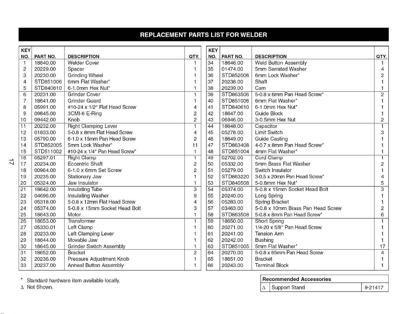
Model 351.21 4300
Figure 15 - Replacement Parts Illustration for Wheels and Speed Handle
9
8
5
2 3 4
]
26
70,
36
J
61
\ 62
29 30
"_33 o_
64
45
44 22
t t
51 54 55
18
KEY
NO.
1
2
3
4
5
6
7
8
9
10
11
12
13
14
15
16
17
18
19
2O
21
22
23
24
25
26
27
28
29
30
31
32
33
34
35
36
PART NO.
01900.00
18660.00
STD315555
04790.00
18662.00
16949.00
16954.00
16955.00
STD852010
16943.00
16957.00
16948.00
16942.00
00088.00
16956.00
18663.00
17727.00
16946.00
16944.00
STD851010
STD852010
00964.00
00958.00
16951.00
STD851012
STD840508
STD841217
16984.00
STD863508
16959.00
STD835025
STD852008
16958.00
20259.00
16985.00
18656.00
DESCRIPTION
3AMI-25 Retaining Ring
Tread
6005ZZ Bearing*
3BMI-47 Retaining Ring
Upper Wheel
Nut
Stud
Pivot
10-1.5 x 30mm Hex Head Bolt*
Guide
Shaft
Slide Block
Housing
5/8"-11 Hex Nut (LH Thread)
Tilt Actuator
Lead Screw
Spacer
Spring
Plate
lOmm Flat Washer*
lOmm Lock Washer*
6-1.0 x 6mm Set Screw
8-1.25 x 8mm Set Screw
Eye Bolt
12mm Flat Washer*
5-0.8mm Hex Nut*
12-1.75mm Hex Nut*
Speed Operator Shaft
5-0.8 x 8mm Pan Head Screw*
Knob
8-1.25 x 25mm Hex Head Bolt*
8mm Lock Washer*
Housing
140 x 1/2 x .025" Blade,
14 Rake
Pillow Block
(Includes One Key No. 52)
Upper Door
QTY.
1
2
2
2
1
1
1
1
10
2
1
1
1
2
1
1
2
1
1
10
6
7
5
1
1
4
1
1
12
1
3
3
1
1
* Standard hardware item available locally.
N/A Not available as repair part.
KEY
NO.
37
38
39
40
41
42
43
44
45
46
47
48
49
5O
51
52
53
54
55
56
57
58
59
6O
61
62
63
64
65
66
67
68
69
70
PART NO.
16992.00
16947.00
06169.00
STD851006
25404.00
N/A
17694.00
18707.00
18658.00
16979.00
17693.00
16981.00
07305.00
16974.00
STD870825
18708.00
STD840610
18659.00
09720.00
STD851008
STD840812
16995.00
18007.00
17728.00
18664.00
17696.00
17689.00
STD851005
17690.00
17741.00
18657.00
STD833016
17692.00
17691.00
DESCRIPTION
5 x 5 x 16mm Key
Handwheel
3AM1-18 Retaining Ring
6mm Flat Washer*
Blade Guard
Cabinet
Gasket
Flange Bushing
Gearbox Housing (Includes
Key Nos. 44 and One 52)
Thrust Bearing
Dust Deflector
Collar
Handle
Handwheel
8-1.25 x 25mm Socket
Head Bolt*
Bushing
6-1.0mm Hex Nut*
Cover
5-0.8 x lOmm Hex Head Bolt
8mm Flat Washer*
8-1.25mm Hex Nut*
7x7x3OmmKey
10-1.5 x 25mm Socket
Head Bolt (LH)
Spacer
Lower Wheel
Ring
Chip Brush
5mm Flat Washer*
Bracket
4.8-2.1 x 8mm Thread
Forming Screw
Lower Door
6-1.0 x 16mm Hex Head Bolt*
Door Handle
Spring Latch
QTY.
2
1
2
4
1
1
1
1
1
2
2
2
1
1
4
2
4
1
3
2
2
1
1
1
1
1
1
8
1
2
1
4
2
4
19
Model 351.214300
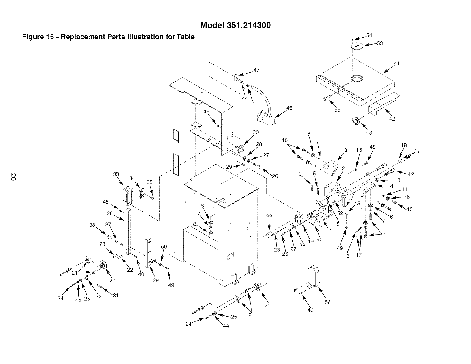
Figure 16 - Replacement Parts Illustration for Table
r,o
o
38 37
23 _
24
44:25 32
20
30
*'/28
\
20
21
46
10
5
26
6
11
9 4(
28
55
43
49
16 17
1
\
42
18
KEY
NO.
1
2
3
4
5
6
7
8
9
10
11
12
13
14
15
16
17
18
19
2O
21
22
23
24
25
26
27
28
PART NO.
17697.00
17698.00
17699.00
17700.00
01002.00
STD851010
STD852010
STD841015
STD836030
STD836045
17729.00
20028.00
STD851012
STD833012
17730.00
17731.00
01286.00
17732.00
17701.00
17702.00
17703.00
17704.00
17705.00
STD833025
STD851006
STD835030
STD852008
STD851008
DESCRIPTION
Table Support
Frame
Left Table Bracket
Right Table Bracket
10-1.5 x 25mm Socket Head Bolt
lOmm Flat Washer*
lOmm Lock Washer*
10-1.5mm Hex Nut*
10-1.5 x 30mm Hex Head Bolt*
10-1.5 x 45mm Hex Head Bolt*
Roller
12-1.75 x 55mm Socket Head Bolt
12mm Flat Washer*
6-1.0 x 12mm Hex Head bolt*
Pointer
Scale
Rivet
Scale
Blade Guide Support
Blade Guide Bracket
Blade Guide
Blade Thrust Guide
Pin
6-1.0 x 25mm Socket Head Bolt*
6mm Flat Washer*
8-1.25 x 30mm Hex Head Bolt*
8mm Lock Washer*
8mm Flat Washer*
QTY.
1
1
1
1
2
11
7
3
4
4
4
2
2
2
2
1
4
1
1
2
4
2
2
4
4
6
6
6
KEY
NO.
29
30
31
32
33
34
35
36
37
38
39
40
41
42
43
44
45
46
47
48
49
5O
51
52
53
54
55
56
PART NO.
08560.00
16962.00
18665.00
02702.00
17707.00
17708.00
02614.00
17709.00
17710.00
17711.00
25405.00
00964.00
25406.00
17714.00
1771 5.00
STD852006
STD541350
20011.00
20012.00
STD870612
STD863508
STD851005
08089.00
00351.00
08609.00
08634.00
08331.00
25305.00
DESCRIPTION
8-1.25 x 15mm Set Screw
Knob
Air Nozzle
Clamp
Housing
Spring
5-0.8 x lOmm Flat Head Screw
Guide Post
Rod
Handle
Blade Guard
6-1.0 x 6mm Set Screw
Work Table
Rip Fence
Knob
6mm Lock Washer*
1/2"-20 Hex Jam Nut*
Lamp
Bracket
6-1.0 x 12mm Socket Head Bolt*
5-0.8 x 8mm Pan Head Screw*
5mm Flat Washer*
10-1.5 x 45mm Socket Head Bolt
6-1.0 x lOmm Set Screw
Table Insert
4 x 12mm Spring Pin
Table Stud
Lower Blade Guard
QTY.
4
1
1
1
1
1
4
1
1
1
1
4
1
1
1
6
1
1
1
1
6
2
1
1
1
1
1
1
* Standard hardware item available locally.
Model 351.21 4300
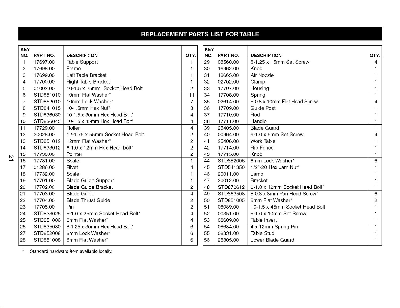
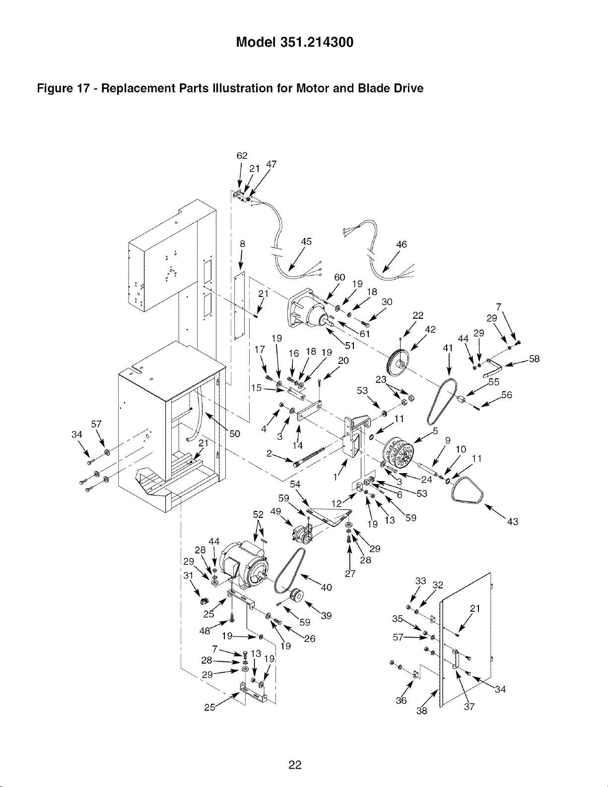
Figure 17 - Replacement Parts Illustration for Motor and Blade Drive
34
57
9
10
11
44
43
33 32
22
KEY
NO.
1
2
3
4
5
6
7
8
9
10
11
12
13
14
15
16
17
18
19
2O
21
22
23
24
25
26
27
28
29
30
31
32
PART NO.
17716.00
16966.00
09849.00
15128.00
20069.00
20256.00
STD835020
20255.00
16968.00
17733.00
00256.00
16969.00
STD843015
16970.00
18667.00
STD836020
STD836045
STD852010
STD851010
STD835035
STD863508
00958.00
STD841217
03914.00
16972.00
STD836035
STD835015
STD852008
STD851008
STD836040
00582.00
STD851005
Speed Change Shaft Housing
Speed Change Shaft
1/2" Flat Washer
1/2"-12 Fiber Hex Nut
Variable Pulley Assembly
Hex Nut
8-1.25 x 20mm Hex Head Bolt*
Reset Cover
Pulley Shaft
Grease Fitting
3AMI-20 Retaining Ring
Shaft Block
10-1.5mm Fiber Hex Nut*
Pulley Shaft Arm
Gear Shaft Arm
10-1.5 x 20mm Hex Head Bolt*
10-1.5 x 45mm Hex Head Bolt*
lOmm Lock Washer*
lOmm Flat Washer*
8-1.25 x 35mm Hex Head Bolt*
5-0.8 x 8mm Pan Head Screw*
8-1.25 x 8mm Set Screw
12-1.75mm Hex Nut*
1/2-12 x 2" Hex Head Bolt
Bracket
10-1.5 x 35mm Hex Head Bolt*
8-1.25 x 15mm Hex Head Bolt*
8mm Lock Washer*
8mm Flat Washer*
10-1.5 x 40mm Hex Head Bolt*
Strain Relief
5mm Flat Washer*
DESCRIPTION QTY.
1
1
2
1
1
1
4
1
1
1
2
1
3
1
1
1
1
5
13
1
14
1
2
1
2
2
6
8
12
4
1
2
* Standard hardware item available locally.
A Not Shown.
KEY
NO.
33
34
35
36
37
38
39
40
41
42
43
44
45
46
47
48
49
50
51
52
53
54
55
56
57
58
59
6O
61
62
A
PART NO.
STD840508
STD833016
STD840610
17691.00
17692.00
18668.01
18669.00
20014.00
17723.00
18670.00
17724.00
STD840812
16975.00
17734.00
07346.00
05188.00
20015.00
18675.00
20253.00
22489.00
20254.00
16680.00
16977.00
STD833035
STD851006
18673.00
00964.00
06635.00
18674.00
16982.00
25173.01
5-0.8mm Hex Nut*
6-1.0 x 16mm Hex Head Bolt*
6-1.0mm Hex Nut*
Latch
Handle
Door
Motor Pulley
M-19 V-Belt
17-360 V-Belt
Speed Reducer Pulley
17-320 V-belt
8-1.25mm Hex Nut*
Line Cord
Motor Cord
Strain Relief
8-1.25 x 20mm Carriage Bolt
Air Pump
Air Hose
Gear Reducer
Motor with Key
Thrust Bearing
Plate
Sensor Target
6-1.0 x 35mm
Socket Head Bolt*
6mm Flat Washer*
Bracket
6-1.0 x 6mm Set Screw
8-1.25 x 20mm Set Screw
7x7x38mmKey
Strain Relief Plate
Operator's Manual
DESCRIPTION QTY.
2
5
2
2
1
1
1
1
1
1
1
6
1
1
1
4
1
1
1
1
2
1
1
1
5
1
5
4
1
1
1
23

iiii_iiiii_iiiii_iiiii_iiiii_iiiii_iii!ii:....
_!_iiiiiii!!iiiiiiiiiii!!_iiiiil
iiiiiiiiiiiiiiiiiiiiiiiiiiiii_'
iiiiiiiiiiiiiiiiiiiiii!_,, Your Home ';,_iiiiiiiiiiiiiiiiiii!!i!!!
iiiiiiiiiiiiiiiiiiiiiii For repair- in your home - of all major brand appliances, iiiiiiiiiiiiiiiiiiiiiiiill
iiiHiii!!iiiiiiii!!ii_ iiiiiiiiiiiiiiiii!!iiiiii!
iiiiiiiiiiiiiiiiiiiiiii lawn and garden equipment, or heating and cooling systems, iiiiiiiiiiiiiiiiiiiiiiiiii
iiiiiiiiiiiiiiiiiiiiiii no matter who made it, no matter who sold it! ..........................iiiiiiiiiiiiiiiiiiiii!i!!i
iiiiiiii_iiiiiiii_ii; iiiiiiii!iiiiii!!iii;;!!!!
iiiiiiiiiiiiiiiiiiiiiii For the replacement parts, accessories and iiiiiiiiiiiiiiiiiiiiiiiill
iiiiiiiiiiiiiiiiiiiiiii owner's manuals that you need to do-it-yourself, iiiiiiiiiiiiiiiiiiii!iiiill
iiiiiiiiiiiii_iiiiiii_ iiiiiiii!iiiiii!!iiiii!ill
iiiiiiiiiiiiiiiiiiiiiii For Sears professional installation of home appliances iiiiiiiiiiiiiiiiiiiiiiiiii
iiiiiiiiiiiiiiiiiiiiiii and items like garage door openers and water heaters, iiiiiiiiii!!iiiiiiiiiiiill
iiiiiiiiiiiii_iiiiiii_ iiiiiiiiii!!iiiiiiiiiii!!!
iiiiiiiiiiiiiiiiiiiiiii 1-800-4-MY-HOME ® (1-800-469-4663) iiiiiiiiiiiiiiiiiiiiiiiill
iiiHiii!!iiiiiiii!!ii_ iiiiiiiiiiiiiiiiiiiii!!ill
iiiiiiiiiiiiiiiiiiiiiii Call anytime, day or night (U.S.A. and Canada) iiiiiiiiiiiiiiiiiiiiiii!!!
iii;;iiiiiiiiiiiiiiiii_ iiiiiiii!iiiiii!!iiiiii!!!
iiiiiiiiiiiiiiiiiiiiiii www.sears.cor,w, .sears.ca
iiiiiiiiiiiiiiiiiiiiiii For expert home solutions advice. www.managemyhome.com iiiiiiiiiiiiiiiiiiiiiiiii!
....................... iiiiii;;ii;;!!iiiii!!ii_
iii!!iiiiiiiiiiiiiiiiii iiiiii!!iiii;;iiiiiiiiiiii
iiiiiiiiiiiiiHiiiiiii_ iiiiiiiiiiiiiiiiiii;i;iiii
iiiiiiii_iiiiiiii!iiii Our Home _,,,
,,,H,,HH,,H,,H,,,_ iiiiiiiiiiiii!iiii!!!iiill
iiiii!!iii!iii!iii!iiii For repair of carry-in items like vacuums, lawn equipment, il;i