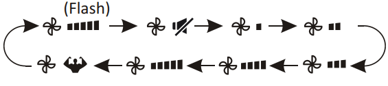
The symbol appears when the unit is turned on, and disappear when the unit is turned off
The symbol appears when power on.
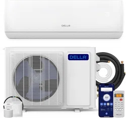
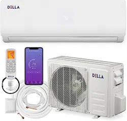
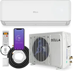
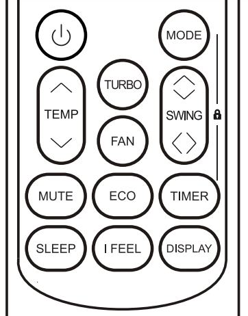
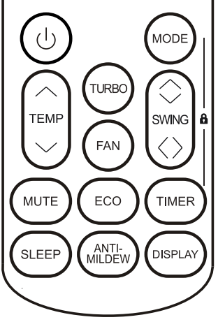
REMOTE CONTROL
Remote control DISPLAY
Battery indicator
Auto Mode
Cooling Mode
Dry Mode
Fan only Mode
Heating Mode
ECO Mode
Timer
Temperature indicator
Fan speed: Auto/ low/ low-mid/ mid/ mid-high/ high
Mute function
TURBO function
Up-down auto swing
Left-right auto swing
SLEEP function
Health function
I FEEL function
Signal indicator
Gentle wind
Child-Lock
Display ON/OFF
Auti-Mildew
To turn on/off the air conditioner .
To decrease temperature, or Timer setting hours.
To increase temperature, or Timer setting hours.
To select the mode of operation (AUTO, COOL, DRY, FAN, HEAT).
To activate/deactivate the ECO function.
Long press to activate/deactivate the 8 heating function (depending on models).
To activate/deactivate the TURBO function.
To select the fan speed of auto/low/mid/high.
To set the time for timer on/off.
To switch-on/off the function SLEEP.
To switch-on/off the LED display.
To stop or start horizontal louver movement or set the desired up/down air flow direction.
To stop or start horizontal louver movement or set the desired left/rightair flow direction
To switch-on/off the I FEEL function
To switch-on/off the MUTE function.
Long press to activate/deactivate the GEN function (depending on models)
To switch-on/off the ANTI-MILDEW function
To activate/deactivate the CHILD-LOCK function.
To activate/deactivate the SELF-CLEAN function (depending on models).
To activate/deactivate the GENTLE WIND function (depending on models).
To activate/deactivate the HEALTH function (depending on models)
Replacement of Batteries
Remove the battery cover plate from the rear of the remote control, by sliding it in direction as the arrow. Install the batteries according the direction (+ and -)shown on the Remote Control. Reinstall the battery cover by sliding it into place.
Use 2 pieces LRO3 AAA (1.5V) batteries. Do not use rechargeable batteries. Replace the old batteries with new ones of the same type when the display is no longer legible. Do not dispose batteries as unsorted municipal waste. Collection of such waste separately for special treatment is necessary.
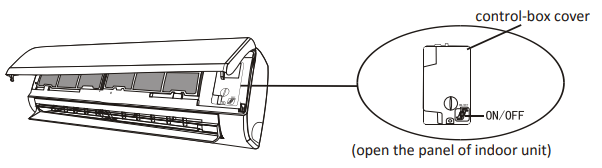
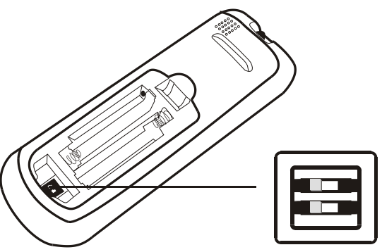
For some model of remote controller, open the battery cover, and you can see the manual switch at the bottom, then you can select the Cooling only or Heating pump, operate as below.
“C” : The display is adjusted in degree celsius.
"F" : The display is adjusted in degree Fahrenheit.
“Cool” : The display is adjusted in only cooling mode
“Heat” : The display is adjusted in cooling and heating mode
1. Direct the remote control toward the Air conditioner.
2. Check that there are no objects between the remote control and the Signal receptor in the indoor unit.
3. Never leave the remote control exposed to the rays of the sun.
4. Keep the remote control at a distance of at least 1m from the television or other electrical appliances.
COOLING MODE
The cooling function allows the air conditioner to cool the room and reduce Air humidity at the same time.
To activate the cooling function (COOL), press the MODE button until the symbol appears on the display. With the button or set a temperature lower than that of the room.
FAN MODE (Not FAN button)
Fan mode, air ventilation only. To set the FAN mode, press MODE until appears on the display.
AUTO MODE
Automatic mode. To set the AUTO mode, press MODE until appears on the display. In AUTO mode the run mode will be set automatically according to the room temperature.
HEATING MODE
The heating function allows the air conditioner to heat the room.
To activate the heating function (HEAT), press the MODE button until the symbol appears on the display. With the button or set a temperature higher than that of the room.
FAN SPEED function (FAN button)
Change the operating fan speed. Press FAN button to set the running fan speed, it can be set to AUTO/ MUTE/ LOW/ LOW-MID / MID/ MID-HIGH/ HIGH/ TURBO speed circularly.
Child-Lock function
1. Long press MODE and TIMER button together to active this function, and do it again to deactivate this function.
2. Under this function, no single button will active.
TIMER function ---- TIMER ON
To automatic switch on the appliance. TIMER function ---- TIMER OFF To automatic switch off the appliance. When the unit is switch-off, you can set the TIMER ON.
1. Press TIMER button first time to set the switch-on, and will appear on the remote display and flashes.
2. Press or to button to set desired Timer-on time. Each time you press the button, the time increases/decreases by half an hour between 0 and 10 hours and by one between 10 and 24 hours.
3. Press TIMER button second time to confirm.
4. After Timer-on setting, set the needed mode (Cool/ Heat/ Auto/ Fan/ Dry), by press the MODE button. And set the needed fan speed, by press FAN button. And press or to set the needed operation temperature.
CANCEL it by press TIMER button.
TIMER function ---- TIMER OFF
To automatic switch off the appliance. When the unit is switch-off, you can set the TIMER ON. To set the time of automatic switch-on as below: When the unit is switch-on, you can set the TIMER OFF. To set the time of automatic switch-off, as below:
1. Confirm the appliance is ON.
2. Press the TIMER button at first time to set the switch-off. Press or to set the needed timer.
3. Press TIMER button at the second time to confirm. CANCEL it by press TIMER button.
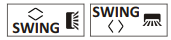
SWING function
1. Press the button SWING to activate the louver,
1.1 Press to activate the horizontal flaps to swing from up to down, the will appear on the remote display. Press again to stop the swing movement at the current angle.
1.2 Press to active the vertical deflectors to swing from left to right, the will appear on the remote display. Press again to stop the swing movement at the current angle.
2. If the vertical deflectors are positioned manually which placed under the flaps, they allow to move the air flow direct to rightward or leftward.
3. For some inverter heating models, press horizontal SWING and vertical SWING together button at the same time, it will activate the Self-Clean function.
TURBO function
To activate turbo function, press the TURBO button, and will appear on the display. Press again to cancel this function. In COOL/ HEAT mode, when you select TURBO feature, the appliance will turn to quick COOL or quick HEAT mode, and operate the highest fan speed to blow strong airflow.
MUTE function
1. Press MUTE button to active this function, and will appears on the remote display. Do it again to deactivate this function.
2. When the MUTE function runs, the remote controller will display the auto fan speed, and the indoor unit will operate at lowest fan speed to be quiet feeling.
3. When press FAN/ TURBO/ SLEEP button, the MUTE function will be cancel. MUTE function can not be activated under dry mode.
SLEEP function
Pre-setting automatic operating program.
Press SLEEP button to activate the SLEEP function, and appears on the display. Press again to cancel this function.
After 10 hours running in sleep mode, the air conditioner will change to the previous setting mode.
I FEEL function (Optional)
Press I FEEL button to active the function, the will appear on the remote display. Do it again to deactivate this function. This function enables the remote control to measure the temperature at its current location, and send this signal to the air conditioner to optimize the temperature around you and ensure the comfort. It will automatically deactivate 2 hours later.
ECO function
In this mode the appliance automatically sets the operation to save energy.
Press the ECO button, the appears on the display, and the appliance will run in ECO mode. Press again to cancel it.
DISPLAY function (Indoor display)
Switch ON/OFF the LED display on panel. Press DISPLAY button to switch off the LED display on the panel. Press again to switch on the LED display.
ANTI-MILDEW function (Optional)
Press button to activate the ANTI-MILDEW function, will appear on the display. Do it again to deactivate this function. After running COOL/ DRY for more than 30 minutes, you can operate this function, the unit will blow airflow for about 15 minutes to dry the inner parts to avoid mildew, then shuts off the unit.
SELF-CLEAN function (Optional)
Only optional for some heating pump inverter appliance. To active this function, turn off the indoor unit at first, then press and button at the same time toward the indoor unit, until hear a beep, and will appear on the remote controller display and the indoor LED display
1. This function helps carry away the accumulated dirt, bacteria, etc from the indoor evaporator.
2. This function will run about 30 minutes, and it will return to the pre-setting mode. You can press button to cancel this function during the process. You will hear 2 beeps when it's finished or cancelled.
8 heating function (Optional)
1. Long press ECO button over 3 seconds to active this function, and ( ) will appear on the remote display. Do it again to deactivate this function.
2. This function will auto start the heating mode o when the room temperature is lower than (), and it will return to standby if the o o temperature reaches (). o
3. If the room temperature is higher than o (), the appliance will cancel this function automatically.
Gentle Wind function (Optional)
1. Turn on the indoor unit, and change to COOL mode, then long press FAN and MUTE button together 3 seconds to active this function, will appear on the display. Do it again to deactivate it.
2. This function will auto close the vertical flaps, and give you the comfortable gentle wind feeling.
Health function (Optional)
1. Turn on the indoor unit at first, and long press SLEEP and DISPLAY button together 3 seconds to active this function, will appear on the display. Do it again to deactivate it.
2. When the HEALTH function is initiated, the Ionizer/ Plasma/ Bipolar Ionizer/ UVC Lights (depending on models) will be energized and running
GEN function (Optional)
1. Turn on the indoor unit at first, and long press MUTE button 3 seconds to active, and do it again to deactivate this function.
2. Under this function, short press MUTE button to select the General type L3 - L2 - L1 - OF.
3. Select OF and wait 2 seconds to exit it.
OPERATION INSTRUCTIONS
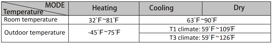
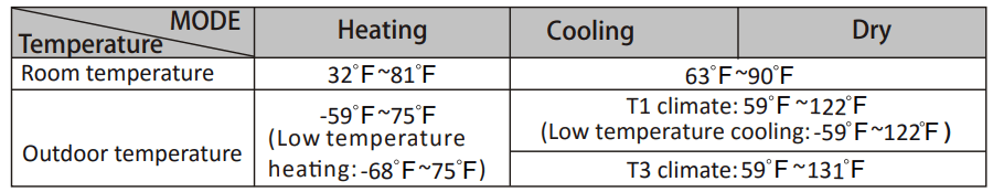
Attempt to use the air conditioner under the temperature beyond the specified range may cause the air conditioner protection device to start and the air conditioner may fail to operate. Therefore, try to use the air conditioner in the following temperature conditions.
Fixed air conditioner:
Inverter air conditioner:
With the power supply connected, restart the air conditioner after shutdown, or switch it to other mode during operation, and the air conditioner protection device will start. The compressor will resume operation after 3 minutes.
Characteristics of heating operation (applicable to Heating pump) Preheating:
When the heating function is enabled, the indoor unit will take 2~5 minutes for preheating, after that the air conditioner will start heating and blows warm air.
Defrosting:
During heating, when the outdoor unit frosted, the air conditioner will enable the automatic defrosting function to improve the heating effect. During defrosting, the indoor and outdoor fans stop running. The air conditioner will resume heating automatically after defrosting finish.
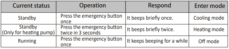
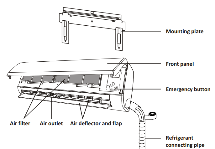
Emergency button:
Open the panel and find the emergency button on the electronic control box when the remote controller fails . (Always press the emergency button with insulation material.)
INSTALLATION PRECAUTIONS
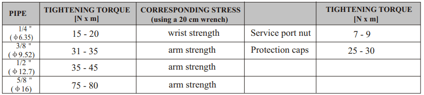
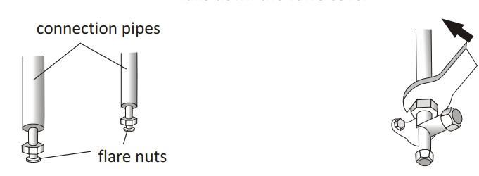
TIGHTENING TORQUE FOR PROTECTION CAPS AND FLANGE CONNECTION
INDOOR UNIT INSTALLATION
Step1: Select Installation location
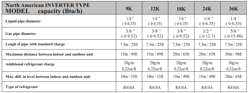
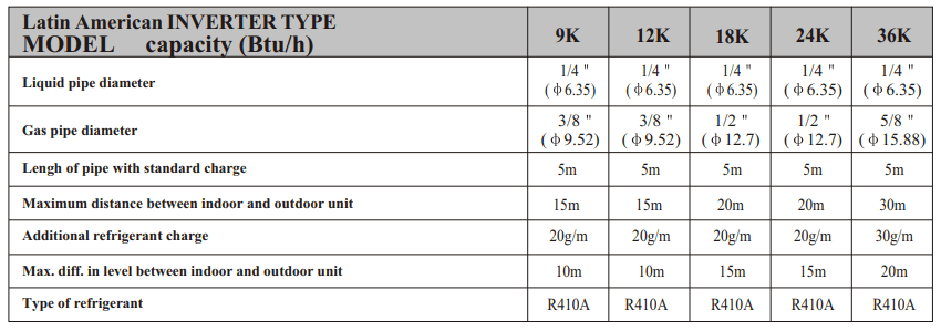
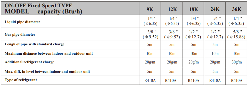
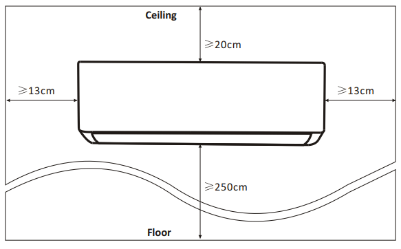
1.1 Ensure the installation complies with the installation minimum dimensions (defined below) and meets the minimum and maximum connecting piping length and maximum change in elevation as defined in the System Requirements section.
1.2 Air inlet and outlet will be clear of obstructions, ensuring proper airflow throughout the room.
1.3 Condensate can be easily and safely drained.
1.4 All connections can be easily made to outdoor unit.
1.5 Indoor unit is out of reach of children.
1.6 A mounting wall strong enough to withstand four times the full weight and vibration of the unit.
1.7 Filter can be easily accessed for cleaning.
1.8 Leave enough free space to allow access for routine maintenance.
1.9 Install at least 10 ft. (3 m) away from the antenna of TV set or radio. Operation of the air conditioner may interfere with radio or TV reception in areas where reception is weak. An amplifier may be required for the affected device.
1.10 Do not install in a laundry room or by a swimming pool due to the corrosive environment.
Minimum Indoor Clearances
Step2: Install Mounting Plate
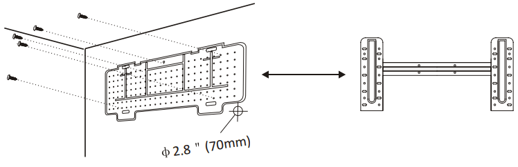
2.1 Take the mounting plate from the back of indoor unit.
2.2 Ensure to meet the minimum installation dimension requirements as step 1, according to the size of mounting plate, determine the position and stick the mounting plate close to the wall.
2.3 Adjust the mounting plate to a horizontal state with a spirit level, then mark out the screw hole positions on the wall.
2.4 Put down the mounting plate and drill holes in the marked positions with drill.
2.5 Insert expansion rubber plugs into the holes, then hang the mounting plate and fix it with screws.
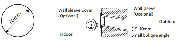
Step3: Drill Wall Hole
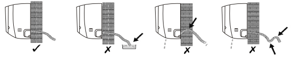
A hole in the wall should be drilled for refrigerant piping ,the drainage pipe, and connecting cables.
3.1 Determine the location of wall hole base on the position of mounting plate.
3.2 The hole should be have a 70mm diameter at least and a small oblique angle to facilitate drainage.
3.3 Drill the wall hole with 70mm core drill and with small oblique angle lower than the indoor end about 5mm to 10mm.
3.4 Place the wall sleeve and wall sleeve cover(both are optional parts) to protect the connection parts.
Caution: When drill the wall hole, maker sure to avoid wires, plumbing and other sensitive components.
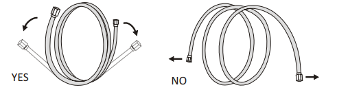
Step4: Connecting Refrigerant Pipe
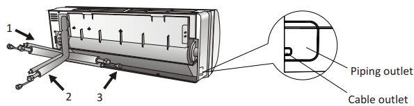
4.1 According to the wall hole position, select the appropriate piping mode. There are three optional piping modes for indoor units as shown in the figure below: In Piping Mode 1 or Piping Mode 3, a notch should be made by using scissors to cut the plastic sheet of piping outlet and cable outlet on the corresponding side of the indoor unit.
Note: When cutting off the plastic sheet at the outlet, the cut should be trimmed to smooth.
4.2 Bending the connecting pipes with the port facing up as shown in the figure.
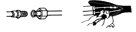
4.3 Take off the plastic cover in the pipe ports and take off the protective cover on the end of piping connectors.
4.4 Check whether there is any sundry on the port of the connecting pipe and make ensure the port is clean.
4.5 After align the center, rotate the nut of the connecting pipe to tighten the nut as tightly as possible by hand.
4.6 Use a torque wrench to tighten it according to the torque values in the torque requirements table; (Refer to the torque requirements table on section INSTALLATION PRECAUTIONS)
4.7 Wrap the joint with the insulation pipe.
Step5: Connect Drainage Hose
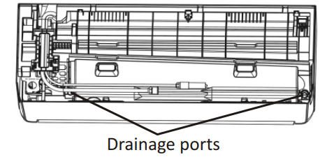
5.1 Adjust the drainage hose(if applicable) In some model, both sides of the indoor unit are provided with drainage ports, you can choose one of them to attache the drainage hose. And plug the unused drain port with the rubber attached in one of the ports.
5.2 Connect the drainage hose to the drainage port, ensure the joint is firm and the sealing effect is good.
5.3 Wrap the joint firmly with teflon tape to ensure no leaks.
Note: Make sure there is no twists or dents, and the pipes should be placed obliquely downward to avoid blockage, to ensure proper drainage.
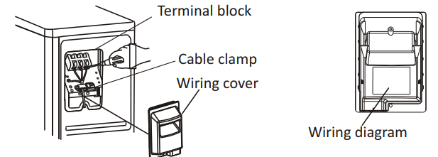
Step6: Connect Wiring
6.1 Choose the right cables size determined by the maximum operating current on the nameplate. (Check the cables size refer to section INSTALLATION PRECAUTIONS)
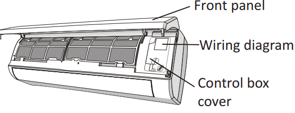
6.2 Open the front panel of indoor unit.
6.3 Use a screwdriver, open the electric control box cover, to reveal the terminal block.
6.4 Unscrew the cable clamp.
6.5 Insert one end of the cable into the position of control box from the back of the right end of the indoor unit.
6.6 Connect the wires to corresponding terminal according to the wiring diagram on the electric control box cover. And make sure that they are well connected.
6.7 Screw the cable clamp to fasten the cables.
6.8 Reinstall the electric control box cover and front panel.
Step7: Wrap Piping and Cable
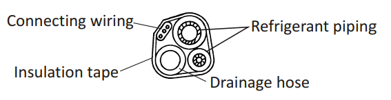
After the refrigerant pipes, connecting wires and drainage hose are all installed, in order to save space, protect and insulate them, it must be bundle with insulating tape before passing them through the wall hole.
7.1 Arrange the pipes ,cables and drainage hose well as the following picture.
7.2 Using the insulating tape wrap the refrigerant pipes, connecting wires and drainage hose together tightly.
Step8: Mount Indoor Unit
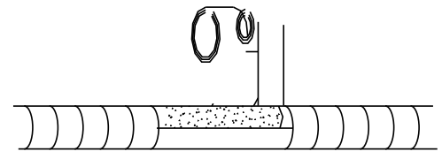
8.1 Slowly pass the refrigerant pipes, connecting wires and drainage hose wrapped bundle through the wall hole.
8.2 Hook the top of indoor unit on the mounting plate.
8.3 Apply slight pressure to the left and right sides of the indoor unit, make sure the indoor unit is hooked firmly.
8.4 Push down the bottom of indoor unit to let the snaps onto the hooks of the mounting plate, and make sure it is hooked firmly.
Sometimes, if the refrigerant pips were already embedded in the wall, or if you want to connecting the pips and wires on the wall, do as below:
(I) Hook the top of the indoor unit on the mounting plate without piping and wiring.
(II) Lift the indoor unit opposite the wall, unfold the bracket on the mounting plate, and use this bracket to prop up the indoor unit, there will be a big space for operation.
(III) Do the refrigerant piping, wiring, connect drainage hose, and wrap them as Step 4 to 7.
OUTDOOR UNIT INSTALLATION
Step1: Select Installation Location
Select a site that allows for the following:
1.1 Do not install the outdoor unit near sources of heat, steam or flammable gas.
1.2 Do not install the unit in too windy or dusty places.
1.3 Do not install the unit where people often pass. Select a place where the air discharge and operating sound will not disturb the neighbors.
1.4 Avoid installing the unit where it will be exposed to direct sunlight ( other wise use a protection, if necessary, that should not interfere with the air flow).
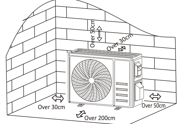
1.5 Reserve the spaces as shown in the picture for the air to circulate freely.
1.6 Install the outdoor unit in a safe and solid place.
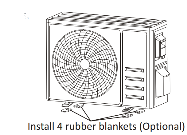
1.7 If the outdoor unit is subject to vibration, place rubber blankets onto the feet of the unit.
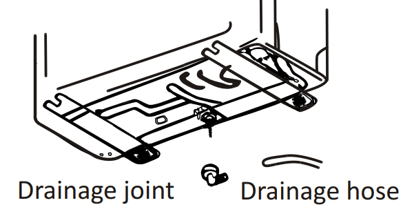
Step2: Install Drainage Hose
2.1 This step only for heating pump models.
2.2 Insert the drainage joint to the hole at the bottom of the outdoor unit.
2.3 Connect the drainage hose to the joint and make the connection well enough.
Step3: Fix Outdoor Unit
3.1 According to the outdoor unit installation dimensions to mark the installation position for expansion bolts .
3.2 Drill holes and clean the concrete dust and place the bolts .
3.3 If applicable install 4 rubber blankets on the hole before place the outdoor unit (Optional). This will reduce vibrations and noise.
3.4 Place the outdoor unit base on the bolts and pre-drilled holes.
3.5 Use wrench to fix the outdoor unit firmly with bolts.
Step4: Install Wiring
4.1 Use a phillips screwdriver to unscrew wiring cover, grasp and press it down gently to take it down.
4.2 Unscrew the cable clamp and take it down.
4.3 According to the wiring diagram pasted inside the wiring cover, connect the connecting wires to the corresponding terminals, and ensure all connections are firmly and securely.
4.4 Reinstall the cable clamp and wiring cover
Step5: Connecting Refrigerant Pipe
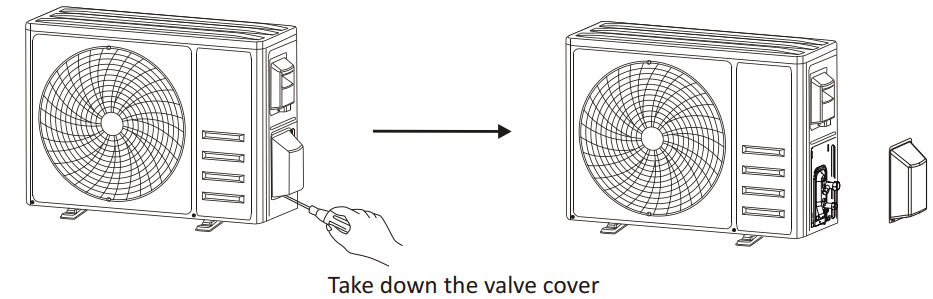
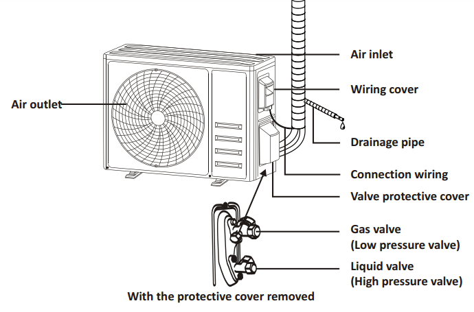
5.1 Unscrews the valve cover, grasp and press it down gently to take it down(if the valve cover is applicable).
5.2 Remove the protective caps from the end of valves.
5.3 Take off the plastic cover in the pipe ports and check whether there is any sundry on the port of the connecting pipe and make ensure the port is clean.
5.4 After align the center, rotate the flare nut of the connecting pipe to tighten the nut as tightly as possible by hand.
5.5 Use a spanner hold the body of the valve and use a torque wrench to tighten the flare nut according to the torque values in the torque requirements table. (Refer to the torque requirements table on section INSTALLATION PRECAUTIONS)
Step6: Vacuum Pumping
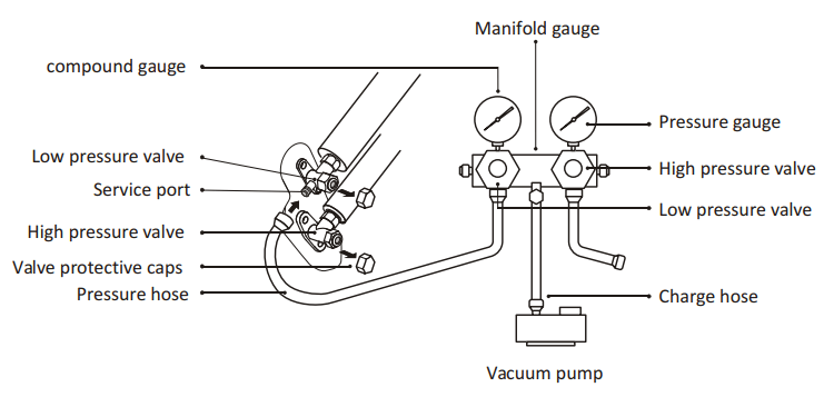
6.1 Use a spanner to take down the protective caps from the service port, low pressure valve and high pressure valve of the outdoor unit.
6.2 Connect the pressure hose of manifold gauge to the service port on the outdoor unit low pressure valve.
6.3 Connect the charge hose from the manifold gauge to the vacuum pump.
6.4 Open the low pressure valve of the manifold gauge and close the high pressure valve.
6.5 Turn on the vacuum pump to vacuum the system
6.6 The vacuum time should not be less than 15 minutes, or make sure the compound gauge indicates -0.1 MPa (-76 cmHg)
6.7 Close the low pressure valve of the manifold gauge and turn off the vacuum.
6.8 Hold the pressure for 5 minutes, make sure that the rebound of compound gauge pointer does not exceed 0.005 MPa.
6.9 Open the low pressure valve counterclockwise for 1/4 turn with hexagonal wrench to let a little refrigerant fill in the system, and close the low pressure valve after 5 seconds and quickly remove the pressure hose.
6.10 Check all indoor and outdoor joints for leakage with soapy water or leak detector.
6.11 Fully open the low pressure valve and high pressure valve of the outdoor unit with hexagonal wrench.
6.12 Reinstall the protective caps of the service port, low pressure valve and high pressure valve of the outdoor unit.
6.13 Reinstall the valve cover
TEST OPERATION
Inspections Before Test Run
Do the following checks before test run
Electrical safety inspection
Check whether the power supply voltage complies with specification.
Check whether there is any wrong or missing connection between the power lines, signal line and earth wires.
Check whether the earth resistance and insulation resistance comply with requirements.
Installation safety inspection
Confirm the direction and smoothness of drainage pipe.
Confirm that the joint of refrigerant pipe is installed completely.
Confirm the safety of outdoor unit, mounting plate and indoor unit installation.
Confirm that the valves are fully open.
Confirm that there are no foreign objects or tools left inside the unit.
Complete installation of indoor unit air inlet grille and panel.
Refrigerant leakage detection
The piping joint, the connector of the two valves of the outdoor unit, the valve spool, the welding port, etc., where leakage may occur.
Foam detection method: Apply soapy water or foam evenly on the parts where leakage may occur, and observe whether bubbles appear or not, if not, it indicates that the leakage detection result is safe.
Leak detector method: Use a professional leak detector and read the instruction of operation, detect at the position where leakage may occur.
The duration of leak detection for each position should last for 3 minutes or more; If the test result shows that there is leakage, the nut should be tightened and tested again until there is no leakage; After the leak detection is completed, wrap the exposed pip connector of indoor unit with thermal insulation material and wrap with insulation tape.
Test Run Instruction
1. Turn on the power supply.
2. Press the ON/OFF button on the remote controller to turn on the air conditioner.
3. Press the Mode button to switch the mode COOL and HEAT. In each mode set as below: COOL-Set the lowest temperature HEAT-Set the highest temperature
4. Run about 8 minutes in each mode and check all functions are properly run and respond the remote controller. Functions check as recommended: 4.1 If the outlet air temperature respond the cool and heat mode 4.2 If the water drains properly from the drainage hose 4.3 If the Louver and deflectors(optional) rotate properly
5. Observe the test run state of the air conditioner at least 30 minutes.
6. After the successfully test run, return the normal setting and press ON/OFF button on the remote controller to turn off the unit.
7. Inform the user to read this manual carefully before use, and demonstrate to the user how to use the air conditioner, the necessary knowledge for service and maintenance, and the reminder for storage of accessories.
MAINTENANCE
Warning
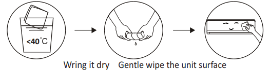
When cleaning, you must shut down the machine and cut off the power supply for more than 5 minutes.
Under no circumstances should the air conditioner be flushed with water.
Volatile liquid (e.g. thinner or gasoline) will damage the air conditioner, so only use soft dry cloth or wet cloth dipped with neutral detergent to clean the air conditioner.
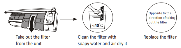
Pay attention to cleaning the filter screen regularly to avoid dust covering which will affect the filter screen effect. When the operating environment is dusty, the cleaning frequency should be increased appropriately.
After removing the filter screen, do not touch the fins of the indoor unit to avoid scratching.
Clean the unit
Tip: Wipe frequently to keep air conditioner clean and good appearance
Clean the filter
Tip: When you find accumulated dust in the filter, please clean the filter in time to ensure the clean, healthy and efficient operation inside the air conditioner.
Service and maintenance
When the air conditioner is not in use for a long time, do the following work: Take out the batteries of the remote controller and disconnect the power supply of the air conditioner.
When starting to use after long-term shutdown:
1. Clean the unit and filter screen;
2. Check whether there are obstacles at the air inlet and outlet of indoor and outdoor units;
3. Check whether the drain pipe is unobstructed; Install the batteries of the remote controller and check whether the power is on.
TROUBLESHOOTING
MALFUNCTION
POSSIBLE CAUSES
The appliance does not operate
Power failure/plug pulled out.
Damaged indoor/outdoor unit fan motor.
Faulty compressor thermomagnetic circuit breaker
Faulty protective device or fuses.
Loose connections or plug pulled out.
It sometimes stops operating to protect the appliance.
Voltage higher or lower than the voltage range.
Active TIMER-ON function.
Damaged electronic control board.
Strange odor
Dirty air filter.
Noise of running water
Back flow of liquid in the refrigerant circulation.
A fine mist comes from the air outlet
This occurs when the air in the room becomes very cold, for example in the COOLING or DEHUMIDIFYING/DRY modes.
A strange noise can be heard
This noise is made by the expansion or contraction of the front panel due to variations in temperature and does not indicate a problem.
Insufficient airflow, eitherhot or cold
Unsuitable temperature setting.
Obstructed air conditioner intakes and outlets.
Dirty air filter.
Fan speed set at minimum.
Other sources of heat in the room.
No refrigerant.
The appliance does not respond to commands
Remote control is not close enough to indoor unit.
The batteries of remote control need to be replaced.
Obstacles between remote control and signal receiver in indoor unit.
The display is off
Active DISPLAY function.
Power failure.
Switch off the air conditioner immediately and cut off the power supply in the event of:
Strange noises during operation.
Faulty electronic control board.
Faulty fuses or switches.
Spraying water or objects inside the appliance.
Overheated cables or plugs.
Very strong smells coming from the appliance.
ERROR CODE ON THE DISPLAY
In case of error, the display on the indoor unit shown the following error codes:
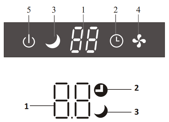
 Indicator for Timer, temperature and Error codes.
 Lights up during Timer operation.
 SLEEP mode
 The symbol appears when the unit is turned on, and disappear when the unit is turned off
 The symbol appears when power on.
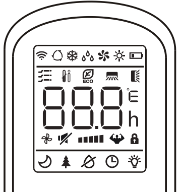
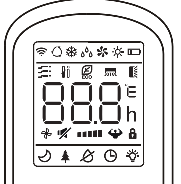
 Battery indicator
 Auto Mode
 Cooling Mode
 Dry Mode
 Fan only Mode
 Heating Mode
 ECO Mode
 Timer
Timer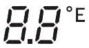 Temperature indicator
 Fan speed: Auto/ low/ low-mid/ mid/ mid-high/ high
 Mute function
 TURBO function
 Up-down auto swing
 Left-right auto swing
 SLEEP function
 Health function
 I FEEL function
 Signal indicator
 Gentle wind
 Child-Lock
 Display ON/OFF
 Auti-Mildew
 To turn on/off the air conditioner .
 To decrease temperature, or Timer setting hours.
 To increase temperature, or Timer setting hours.
 To select the mode of operation (AUTO, COOL, DRY, FAN, HEAT).
 To activate/deactivate the ECO function.
 To activate/deactivate the TURBO function.
 To select the fan speed of auto/low/mid/high.
 To set the time for timer on/off.
 To switch-on/off the function SLEEP.
 To switch-on/off the LED display.
 To stop or start horizontal louver movement or set the desired up/down air flow direction.
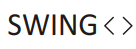 To stop or start horizontal louver movement or set the desired left/rightair flow direction
 To switch-on/off the I FEEL function
 To switch-on/off the MUTE function.
 To switch-on/off the ANTI-MILDEW function
 To activate/deactivate the CHILD-LOCK function.
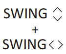 To activate/deactivate the SELF-CLEAN function (depending on models).
 To activate/deactivate the GENTLE WIND function (depending on models).
 To activate/deactivate the HEALTH function (depending on models)
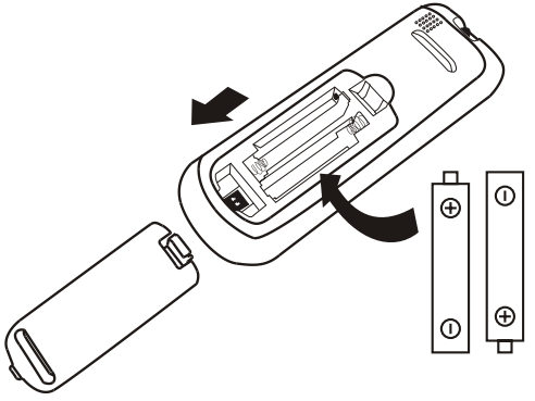

 appears on the display. With the button
 or
or  set a temperature lower than that of the room.
 appears on the display.
 appears on the display. In AUTO mode the run mode will be set automatically according to the room temperature.
 appears on the display. With the button
 or
or set a temperature higher than that of the room.

 and
and 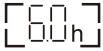 will appear on the remote display and flashes.
 or
or  to button to set desired Timer-on time. Each time you press the button, the time increases/decreases by half an hour between 0 and 10 hours and by one between 10 and 24 hours.
 to activate the horizontal flaps to swing from up to down, the
 will appear on the remote display. Press again to stop the swing movement at the current angle.
 to active the vertical deflectors to swing from left to right, the
  will appear on the remote display. Press again to stop the swing movement at the current angle.
 will appear on the display. Press again to cancel this function. In COOL/ HEAT mode, when you select TURBO feature, the appliance will turn to quick COOL or quick HEAT mode, and operate the highest fan speed to blow strong airflow.

 appears on the display. Press again to cancel this function.
 appear on the remote display. Do it again to deactivate this function. This function enables the remote control to measure the temperature at its current location, and send this signal to the air conditioner to optimize the temperature around you and ensure the comfort. It will automatically deactivate 2 hours later.
 appliance will run in ECO mode. Press again to cancel it.

 will appear on the display. Do it again to deactivate this function. After running COOL/ DRY for more than 30 minutes, you can operate this function, the unit will blow airflow for about 15 minutes to dry the inner parts to avoid mildew, then shuts off the unit.
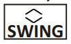 and
and 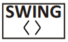 button at the same time toward the indoor unit, until hear a beep, and
  will appear on the remote controller display and the indoor LED display
 button to cancel this function during the process. You will hear 2 beeps when it's finished or cancelled.
 and (
and (  ) will appear on the remote display. Do it again to deactivate this function.
 (
( ), and it will return to standby if the o o temperature reaches
  (
( ). o
). o o (
o ( ), the appliance will cancel this function automatically.
 will appear on the display. Do it again to deactivate it.
 will appear on the display. Do it again to deactivate it.