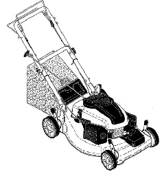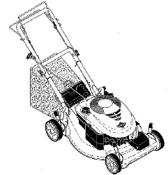
Walk Behind Lawn Mower
Owner/Operator Manual
Manuel Du Proprietaire/Utilisateur
Model
911271 - Pro21
FRAN(_AIS
01326700 2/10
Printed in USA
/ Y:_:] i _ [o]_ _o]_//_/[_
Safety ........................... 4
Assembly ........................ 9
Controls and Features ............ 10
Operation ....................... 11
Maintenance ..................... 15
Service and Adjustments .......... 19
Storage ......................... 22
Troubleshooting ................. 23
Service Parts .................... 24
Accessories ..................... 24
Specifications ................... 25
Warranty ........................ 27
II_/llt_e_o]_l
NON-ENGLISH MANUALS
Manuals in languages other than
English may be obtained from
your Dealer. Visit your dealer or
www.ariens.com for a list of
languages available for your
equipment.
Manuals printed in languages
other than English are also
available as a free download on
our website:
http://www.ariens.com
MANUALES EN IDIOMAS
DIFERENTES DEL INGLES
Puede obtener manuales en
,_ idiomas diferentes del ingles en su
distribuidor. Visite a su distribuidor
o vaya a www.ariens.com para
--_ btener una lista de idiomas
disponibles para su equipo.
Tambien puede imprimir manuales
en idiomas diferentes del ingles
descargandolos gratuitamente de
nuestra pagina Web:
http :llwww.ariens.com
MANUELS NON ANGLAIS
Des manuels dans differentes
,_ langues sont disponibles chez
votre revendeur. Rendez-vous
chez votre revendeur ou allez sur
le site www.ariens.com pour
consulter la liste des langues
disponibles pour votre equipement.
Les manuels imprimes dans des
langues differentes de I'anglais
sont egalement disponibles en
telechargement gratuit sur notre
site Web :
http :llwww.ariens.com
THE MANUAL
Before using the unit, carefully and
completely read your manuals. The contents
will give you an understanding of safety
instructions and controls during normal
operation and maintenance.
All reference to left, right, front, or rear are
given from the operator's position, facing the
direction of forward travel.
SERVICE AND REPLACEMENT
PARTS
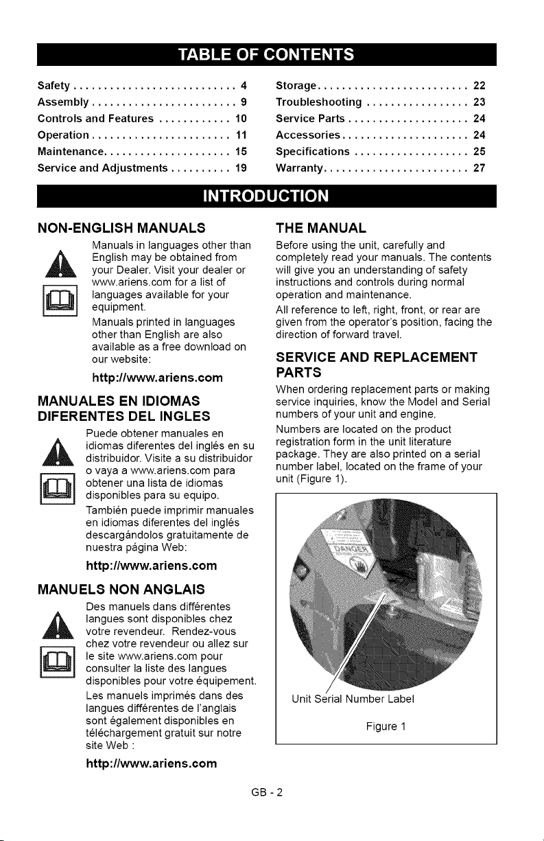
When ordering replacement parts or making
service inquiries, know the Model and Serial
numbers of your unit and engine.
Numbers are located on the product
registration form in the unit literature
package. They are also printed on a serial
number label, located on the frame of your
unit (Figure 1).
Unit Serial Number Label
Figure 1
GB -2
•RecordUnitModelandSerialnumbers
here:
J
• Record Engine Model & Serial numbers
here:
J
PRODUCT REGISTRATION
The Ariens dealer must register the product
at the time of purchase. Registering the
product will help the company process
warranty claims or contact you with the latest
service information. All claims meeting
requirements during the limited warranty
period will be honored, whether or not the
product registration card is returned. Keep a
proof of purchase if you do not register your
unit.
Customer Note: If the Dealer does not
register your product, please fill out, sign and
return the product registration card to Ariens
or go to www.ariens.com on the internet.
UNAUTHORIZED REPLACEMENT
PARTS
Use only Ariens replacement parts.
Replacing any part on this vehicle with
anything other than an Ariens authorized
replacement part may adversely affect the
performance, durability, or safety of this unit
and may void the warranty. Ariens disclaims
liability for any claims or damages, whether
warranty, property damage, personal injury or
death arising out of the use of unauthorized
replacement parts. To locate your nearest
Ariens Dealer, go to www.ariens.com on the
internet.
DEALER DELIVERY
Dealer should:
1. Check that all assembly and
adjustments have been properly
completed.
2. Fill out Original Purchaser Registration
Card and return the card to Ariens.
3. Explain Ariens Limited Warranty Policy.
4. Explain recommended lubrication and
maintenance. Advise customer on
adjustments. Remind customer to
change oil in 4 cycle engine crankcase
after first five (5) hours of operation.
5. Instruct customer on controls and
operation of unit. Discuss and
emphasize the Safety Rules. Give
customer Owner/Operator, Parts, and
Engine manuals. Advise customer to
thoroughly read and understand them.
DISCLAIMER
Ariens reserves the right to discontinue,
make changes to, and add improvements
upon its products at any time without public
notice or obligation.The descriptions and
specifications contained in this manual were
in effect at printing. Equipment described
within this manual may be optional. Some
illustrations may not apply to your unit.
GB-3
[,:'Y-'1==1i'I
WARNING: This cutting machine
is capable of amputating hands
and feet and throwing objects.
Failure to observe the safety
instructions in the manuals and on
decals could result in serious
injury or death.
Slopes are a major factor related
to slip and fall accidents.
Operation on all slopes requires
extra caution.
Tragic accidents can occur if the
operator is not alert to the
presence of children. Never
assume that children will remain
where you last saw them.
Gasoline is extremely flammable
and the vapors are explosive,
handle with care.
Stop unit and engine, remove key
(if equipped) and allow moving
parts to stop before leaving
operator's position.
SAFETY ALERTS
Look for these symbols to point
out important safety precautions.
They mean:
Attention!
Personal Safety Is Involved!
Become Alert!
Obey The Message!
The safety alert symbols above and signal
words below are used on decals and in this
manual.
Read and understand all safety messages.
DANGER: IMMINENTLY
,_ HAZARDOUS SITUATION! If not
avoided, WILL RESULT in death
or serious injury.
WARNING: POTENTIALLY
HAZARDOUS SITUATION! If not
avoided, COULD RESULT in
death or serious injury.
CAUTION: POTENTIALLY
HAZARDOUS SITUATION! If not
avoided, MAY RESULT in minor
or moderate injury. It may also be
used to alert against unsafe
practices.
NOTATIONS
NOTE: General reference information for
proper operation and maintenance practices.
IMPORTANT: Specific procedures or
information required to prevent damage to
unit or attachment.
PRACTICES AND LAWS
Practice usual and customary safe working
precautions, for the benefit of yourself and
others. Understand and follow all safety
messages. Be alert to unsafe conditions and
the possibility of minor, moderate, or serious
injury or death. Learn applicable rules and
laws in your area.
REQUIRED OPERATOR
TRAINING
Original purchaser of this unit was instructed
by the seller on safe and proper operation. If
anyone other than the original purchaser will
use the unit, ALWAYS provide this manual
and any needed safety training before
operation.
GB -4
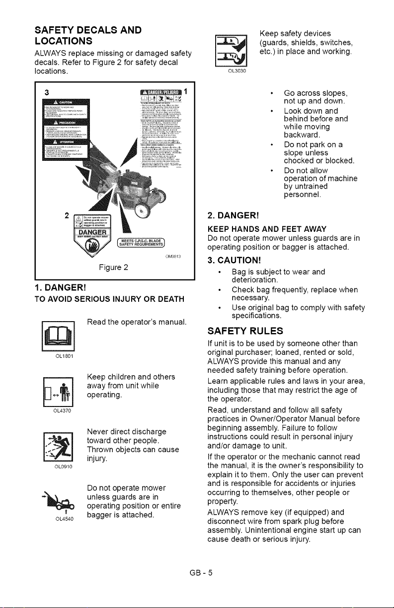
SAFETY DECALS AND
LOCATIONS
ALWAYS replace missing or damaged safety
decals. Refer to Figure 2 for safety decal
locations.
MEETS C.P.S.C. BLADE
OM0813
Figure 2
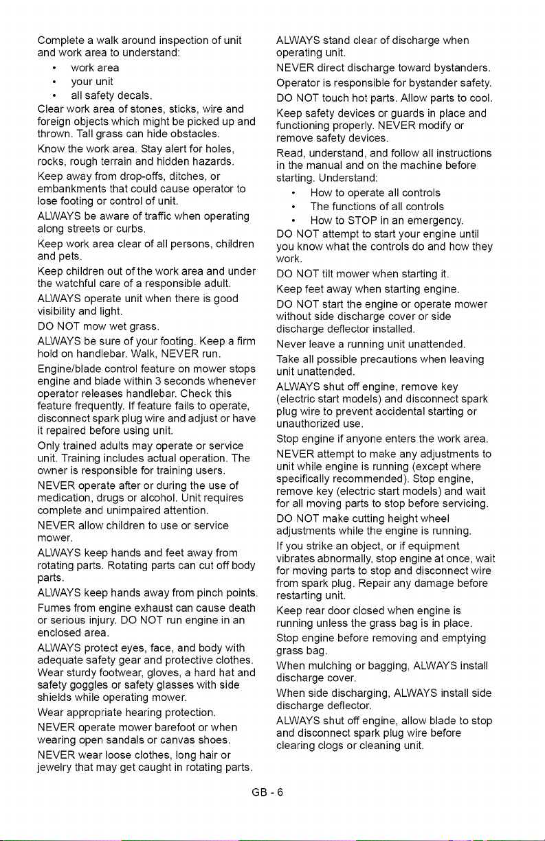
1. DANGER!
TO AVOIDSERIOUS INJURY OR DEATH
©L1801
Read the operator's manual.
Keep children and others
away from unit while
operating.
OL4370
OL0910
Never direct discharge
toward other people.
Thrown objects can cause
injury.
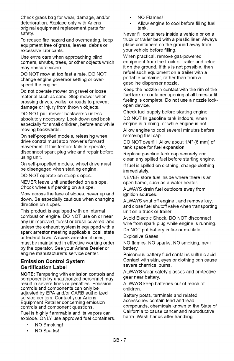
Do not operate mower
-_ unless guards are inoperating position or entire
bagger is attached.
OL4540
OL3030
Keep safety devices
(guards, shields, switches,
etc.) in place and working.
Go across slopes,
not up and down.
Look down and
behind before and
while moving
backward.
Do not park on a
slope unless
chocked or blocked.
Do not allow
operation of machine
by untrained
personnel.
2. DANGER!
KEEP HANDS AND FEET AWAY
Do not operate mower unless guards are in
operating position or bagger is attached.
3. CAUTION!
Bag is subject to wear and
deterioration.
Check bag frequently, replace when
necessary.
Use original bag to comply with safety
specifications.
SAFETY RULES
If unit is to be used by someone other than
original purchaser; loaned, rented or sold,
ALWAYS provide this manual and any
needed safety training before operation.
Learn applicable rules and laws in your area,
including those that may restrict the age of
the operator.
Read, understand and follow all safety
practices in Owner/Operator Manual before
beginning assembly. Failure to follow
instructions could result in personal injury
and/or damage to unit.
If the operator or the mechanic cannot read
the manual, it is the owner's responsibility to
explain it to them. Only the user can prevent
and is responsible for accidents or injuries
occurring to themselves, other people or
property.
ALWAYS remove key (if equipped) and
disconnect wire from spark plug before
assembly. Unintentional engine start up can
cause death or serious injury.
GB-5
Completeawalkaroundinspectionofunit
andworkareatounderstand:
workarea
yourunit
allsafetydecals.
Clearworkareaofstones,sticks,wireand
foreignobjectswhichmightbepickedupand
thrown.Tallgrasscanhideobstacles.
Knowtheworkarea.Stayalertforholes,
rocks,roughterrainandhiddenhazards.
Keepawayfromdrop-offs,ditches,or
embankmentsthatcouldcauseoperatorto
losefootingorcontrolofunit.
ALWAYSbeawareoftrafficwhenoperating
alongstreetsorcurbs.
Keepworkareaclearofallpersons,children
andpets.
Keepchildrenoutoftheworkareaandunder
thewatchfulcareofaresponsibleadult.
ALWAYSoperateunitwhenthereisgood
visibilityandlight.
DONOTmowwetgrass.
ALWAYSbesureofyourfooting.Keepafirm
holdonhandlebar.Walk,NEVERrun.
Engine/bladecontrolfeatureonmowerstops
engineandbladewithin3secondswhenever
operatorreleaseshandlebar.Checkthis
featurefrequently.Iffeaturefailstooperate,
disconnectsparkplugwireandadjustorhave
itrepairedbeforeusingunit.
Onlytrainedadultsmayoperateorservice
unit.Trainingincludesactualoperation.The
ownerisresponsiblefortrainingusers.
NEVERoperateafterorduringtheuseof
medication,drugsoralcohol.Unitrequires
completeandunimpairedattention.
NEVERallowchildrentouseorservice
mower.
ALWAYSkeephandsandfeetawayfrom
rotatingparts.Rotatingpartscancutoffbody
parts.
ALWAYSkeephandsawayfrompinchpoints.
Fumesfromengineexhaustcancausedeath
orseriousinjury.DONOTrunengineinan
enclosedarea.
ALWAYSprotecteyes,face,andbodywith
adequatesafetygearandprotectiveclothes.
Wearsturdyfootwear,gloves,ahardhatand
safetygogglesorsafetyglasseswithside
shieldswhileoperatingmower.
Wearappropriatehearingprotection.
NEVERoperatemowerbarefootorwhen
wearingopensandalsorcanvasshoes.
NEVERwearlooseclothes,longhairor
jewelrythatmaygetcaughtinrotatingparts.
ALWAYSstandclearofdischargewhen
operatingunit.
NEVERdirectdischargetowardbystanders.
Operatorisresponsibleforbystandersafety.
DONOTtouchhotparts.Allowpartstocool.
Keepsafetydevicesorguardsinplaceand
functioningproperly.NEVERmodifyor
removesafetydevices.
Read,understand,andfollowallinstructions
inthemanualandonthemachinebefore
starting.Understand:
Howtooperateallcontrols
Thefunctionsofallcontrols
HowtoSTOPinanemergency.
DONOTattempttostartyourengineuntil
youknowwhatthecontrolsdoandhowthey
work.
DONOTtiltmowerwhenstartingit.
Keepfeetawaywhenstartingengine.
DONOTstarttheengineoroperatemower
withoutsidedischargecoverorside
dischargedeflectorinstalled.
Neverleavearunningunitunattended.
Takeallpossibleprecautionswhenleaving
unitunattended.
ALWAYSshutoffengine,removekey
(electricstartmodels)anddisconnectspark
plugwiretopreventaccidentalstartingor
unauthorizeduse.
Stopengineifanyoneenterstheworkarea.
NEVERattempttomakeanyadjustmentsto
unitwhileengineisrunning(exceptwhere
specificallyrecommended).Stopengine,
removekey(electricstartmodels)andwait
forallmovingpartstostopbeforeservicing.
DONOTmakecuttingheightwheel
adjustmentswhiletheengineisrunning.
Ifyoustrikeanobject,orifequipment
vibratesabnormally,stopengineatonce,wait
formovingpartstostopanddisconnectwire
fromsparkplug.Repairanydamagebefore
restartingunit.
Keepreardoorclosedwhenengineis
runningunlessthegrassbagisinplace.
Stopenginebeforeremovingandemptying
grassbag.
Whenmulchingorbagging,ALWAYSinstall
dischargecover.
Whensidedischarging,ALWAYSinstallside
dischargedeflector.
ALWAYSshutoffengine,allowbladetostop
anddisconnectsparkplugwirebefore
clearingclogsorcleaningunit.
GB-6
Checkgrassbagforwear,damage,and/or
deterioration.ReplaceonlywithAriens
originalequipmentreplacementpartsfor
safety.
Toreducefirehazardandoverheating,keep
equipmentfreeofgrass,leaves,debrisor
excessivelubricants.
Useextracarewhenapproachingblind
corners,shrubs,trees,orotherobjectswhich
mayobscurevision.
DONOTmowattoofastarate.DONOT
changeenginegovernorsettingorover-
speedtheengine.
Donotoperatemowerongravelorloose
materialsuchassand.Stopmowerwhen
crossingdrives,walks,orroadstoprevent
damageorinjuryfromthrownobjects.
DONOTpullmowerbackwardsunless
absolutelynecessary.Lookdownandback,
especiallyforsmallchildren,beforeandwhile
movingbackwards.
Onself-propelledmodels,releasingwheel
drivecontrolmuststopmower'sforward
movement.Ifthisfeaturefailstooperate,
disconnectsparkplugwireandrepairbefore
usingunit.
Onself-propelledmodels,wheeldrivemust
bedisengagedwhenstartingengine.
DONOToperateonsteepslopes.
NEVERleaveunitunattendedonaslope.
Chockwheelsifparkingonaslope.
Mowacrossthefaceofslopes,neverupand
down.Beespeciallycautiouswhenchanging
directiononslopes.
Thisproductisequippedwithaninternal
combustionengine.DONOTuseonornear
anyunimproved,forestorbrushcoveredland
unlesstheexhaustsystemisequippedwitha
sparkarrestormeetingapplicablelocal,state
orfederallaws.Asparkarrestor,ifused,
mustbemaintainedineffectiveworkingorder
bytheoperator.SeeyourAriensDealeror
enginemanufacturer'sservicecenter.
Emission Control System
Certification Label
NOTE: Tampering with emission controls and
components by unauthorized personnel may
result in severe fines or penalties. Emission
controls and components can only be
adjusted by EPA and/or CARB authorized
service centers. Contact your Ariens
Equipment Retailer concerning emission
controls and component questions.
Fuel is highly flammable and its vapors can
explode. ONLY use approved fuel containers.
NO Smoking!
NO Sparks!
NO Flames!
Allow engine to cool before filling fuel
tank.
Never fill containers inside a vehicle or on a
truck or trailer bed with a plastic liner. Always
place containers on the ground away from
your vehicle before filling.
When practical, remove gas-powered
equipment from the truck or trailer and refuel
it on the ground. If this is not possible, then
refuel such equipment on a trailer with a
portable container, rather than from a
gasoline dispenser nozzle.
Keep the nozzle in contact with the rim of the
fuel tank or container opening at all times until
fueling is complete. Do not use a nozzle lock-
open device.
Check fuel supply before starting engine.
DO NOT fill gasoline tank indoors, when
engine is running, or while engine is hot.
Allow engine to cool several minutes before
removing fuel cap.
DO NOT overfill. Allow about 1/4" (6 mm) of
tank space for fuel expansion.
Replace gasoline tank cap securely and
clean any spilled fuel before starting engine.
If fuel is spilled on clothing, change clothing
immediately.
NEVER store fuel inside where there is an
open flame, such as a water heater.
ALWAYS drain fuel outdoors away from
ignition sources.
ALWAYS shut off engine, and remove key,
and close fuel shutoff valve when transporting
unit on a truck or trailer.
Avoid Electric Shock. DO NOT disconnect
wire from spark plug while engine is running.
Do NOT put battery in fire or mutilate.
Explosive Gases!
NO flames, NO sparks, NO smoking, near
battery.
Poisonous battery fluid contains sulfuric acid.
Contact with skin, eyes or clothing can cause
severe chemical burns.
ALWAYS wear safety glasses and protective
gear near battery.
ALWAYS keep batteries out of reach of
children.
Battery posts, terminals and related
accessories contain lead and lead
compounds, chemicals known to the State of
California to cause cancer and reproductive
harm. Wash hands after handling.
GB-7

Chargebatteriesinanopen,well-ventilated
area,awayfromsparkandflames.Unplug
chargerbeforeconnectingordisconnecting
battery.Wearprotectiveclothinganduse
insulatedtools.
Accidentalenginestartupcancausedeathor
seriousinjury.Exceptwherespecifically
recommended,ALWAYSstopengine,
removekey(electricstartmodels),waitfor
movingpartstostop,allowpartstocooland
disconnectsparkplugwirebeforeinspecting,
servicing,adjustingorrepairingunit.
Keepmowerfreeofgrass,leaves,orother
debrisbuild-up.
Keepequipmentingoodcondition.
Maintainorreplacesafetyandinstruction
labels,asnecessary.
Followenginemanufacturer'ssafety
instructionwhenservicingengine.
Checkallhardwareatregularintervals,
especiallybladeattachmentbolts.Keepall
hardwareproperlytightened.
Anextensionspring,whenextended,stores
energyandcanbedangerous.Alwaysuse
toolsspecificallydesignedforinstallingor
removinganextensionspring.Always
compressorextendspringsslowly.
Beforetippingunit,removefuelandbattery(if
equipped).
Useextracarewhenloadingorunloading
unitontotrailerortruck.
Ensureallwheelblocks,jackstandsandtie
downswillsupportunitduringmaintenance.
Replaceworn-outmufflersimmediately.
Continuedusecouldresultinfireor
explosion.
Sharpedgescancutoramputatefingersora
hand.Wrapbladeorwearsturdyglovesto
service.
Onlyreplaceblades.NEVERstraightenor
weldblades.
Useonlyreplacementpartsdesignedforyour
unit.SeeyourAriensDealer.
Allowenginetocoolbeforestoringinany
enclosure.
ALWAYScleanunitbeforeextendedstorage.
Seeenginemanualforproperstorage.
DONOTstoreunitinsideabuildingwithfuel
inthefueltankwhereanyignitionsources
arepresent.
Useonlyaccessorieswhichhavebeen
approvedbyAriensandareproperly
installed.
Useonlyaccessoriesorattachmentsthatare
designedforyourunitandthatcanbeused
safelyonyourterrain.
Checkattachmentsfrequentlyandreplace
wornordamagedcomponentswith
manufacturer'srecommendedparts.
GB-8
7_,_"I,._=1_N-']_'d
CAUTION: AVOID INJURY. Read
,_ and understand the entire Safety
section before proceeding.
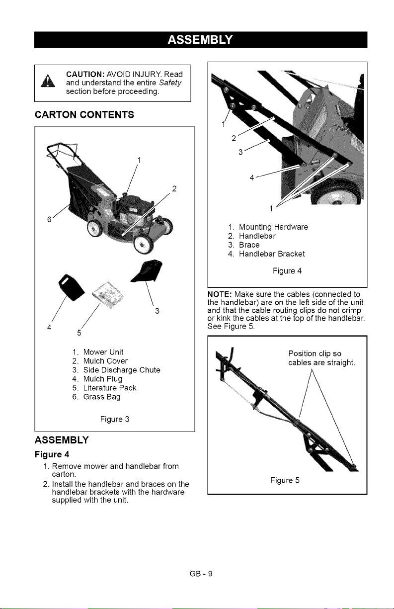
CARTON CONTENTS
1. Mower Unit
2. Mulch Cover
3. Side Discharge Chute
4. Mulch Plug
5. Literature Pack
6. Grass Bag
Figure 3
ASSEMBLY
Figure 4
1. Remove mower and handlebar from
carton.
2. Install the handlebar and braces on the
handlebar brackets with the hardware
supplied with the unit.
1. Mounting Hardware
2. Handlebar
3. Brace
4. Handlebar Bracket
Figure 4
NOTE: Make sure the cables (connected to
the handlebar) are on the left side of the unit
and that the cable routing clips do not crimp
or kink the cables at the top of the handlebar.
See Figure 5.
Position clip so
cables are straight.
Figure 5
GB-9
3.Checktheleveloftheenginecrankcase
oilbeforeeachuse.
NOTE:Theengineisshippedwithoilin
crankcase.RefertoEngineManualfor
detailedinstructions.
4.Set-upmowerforbagging,side
dischargeormulching.SeeMOWER
SET-UP on page 13.
NOTE: The mower ships with the rear wheels
and the front wheels set for different cutting
heights. This position is not suitable for
cutting grass. Before mowing, make sure the
wheels are set at the same cutting height in a
range appropriate for your mowing
conditions.
5. Set the proper cutting height. See
CUTTING HEIGHT ADJUSTMENT on
page 11.
6. Fill fuel tank. See FILLING THE FUEL
TANK on page 12.
7. Connect spark plug wire.
8. Check the engine/blade control feature.
Try starting the engine without the
engine/blade control held against the
handlebar. Engine must not start. If
engine starts, stop engine and bring the
unit to your dealer for adjustment or
repair.
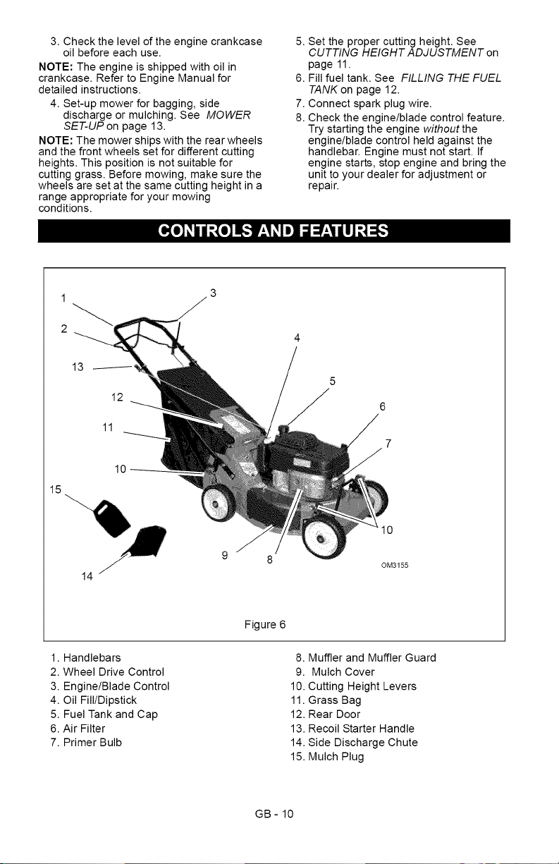
[_o]_il;[o]l[,,,_ E'_lm] lal=r_,_l_-]
1
2
15
13
12
11
10
5
6
14
110
OM3155
Figure 6
1. Handlebars
2. Wheel Drive Control
3. Engine/Blade Control
4. Oil Fill/Dipstick
5. Fuel Tank and Cap
6. Air Filter
7. Primer Bulb
8. Muffler and Muffler Guard
9. Mulch Cover
10. Cutting Height Levers
11. Grass Bag
12. Rear Door
13. Recoil Starter Handle
14. Side Discharge Chute
15. Mulch Plug
GB- 10
[e]_ =I=I±_i[e]_I
CONTROLS AND FEATURES
See Figure 6 for locations.
,_ WARNING: Improper operation
can lead to injury. Learn what the
controls do and how they work.
Thoroughly read and understand
entire Operator Manual.
CAUTION: AVOID INJURY. Read
,_ and understand the entire Safety
section before proceeding.
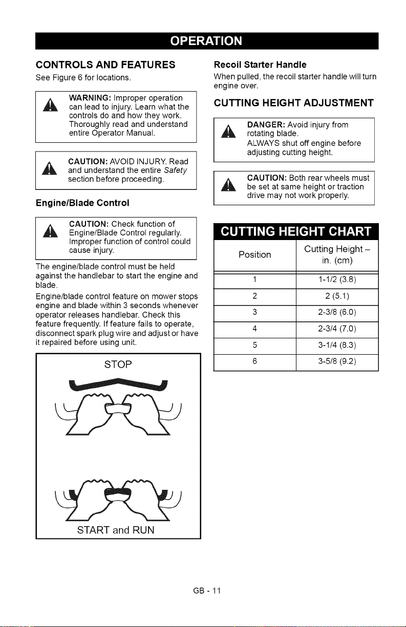
Engine/Blade Control
CAUTION: Check function of
_L, Engine/Blade Control regularly.
Improper function of control could
cause injury.
The engine/blade control must be held
against the handlebar to start the engine and
blade.
Engine/blade control feature on mower stops
engine and blade within 3 seconds whenever
operator releases handlebar. Check this
feature frequently. If feature fails to operate,
disconnect spark plug wire and adjust or have
it repaired before using unit.
STOP
START and RUN
Recoil Starter Handle
When pulled, the recoil starter handle will turn
engine over.
CUTTING HEIGHT ADJUSTMENT
DANGER: Avoid injury from
_, rotating blade.
ALWAYS shut off engine before
adjusting cutting height.
CAUTION: Both rear wheels must
,_ be set at same height or traction
drive may not work properly.
I[qlj i/I_[€']I T,I:
Position
1
2
3
4
5
6
[_-" I IIq-" r_,1:,11iI
Cutting Height-
in. (cm)
1-1/2(3.8)
2 (5.1)
2-3!8 (6.0)
2-3/4 (7.0)
3-1/4 (8.3)
3-5!8 (9.2)
GB- 11
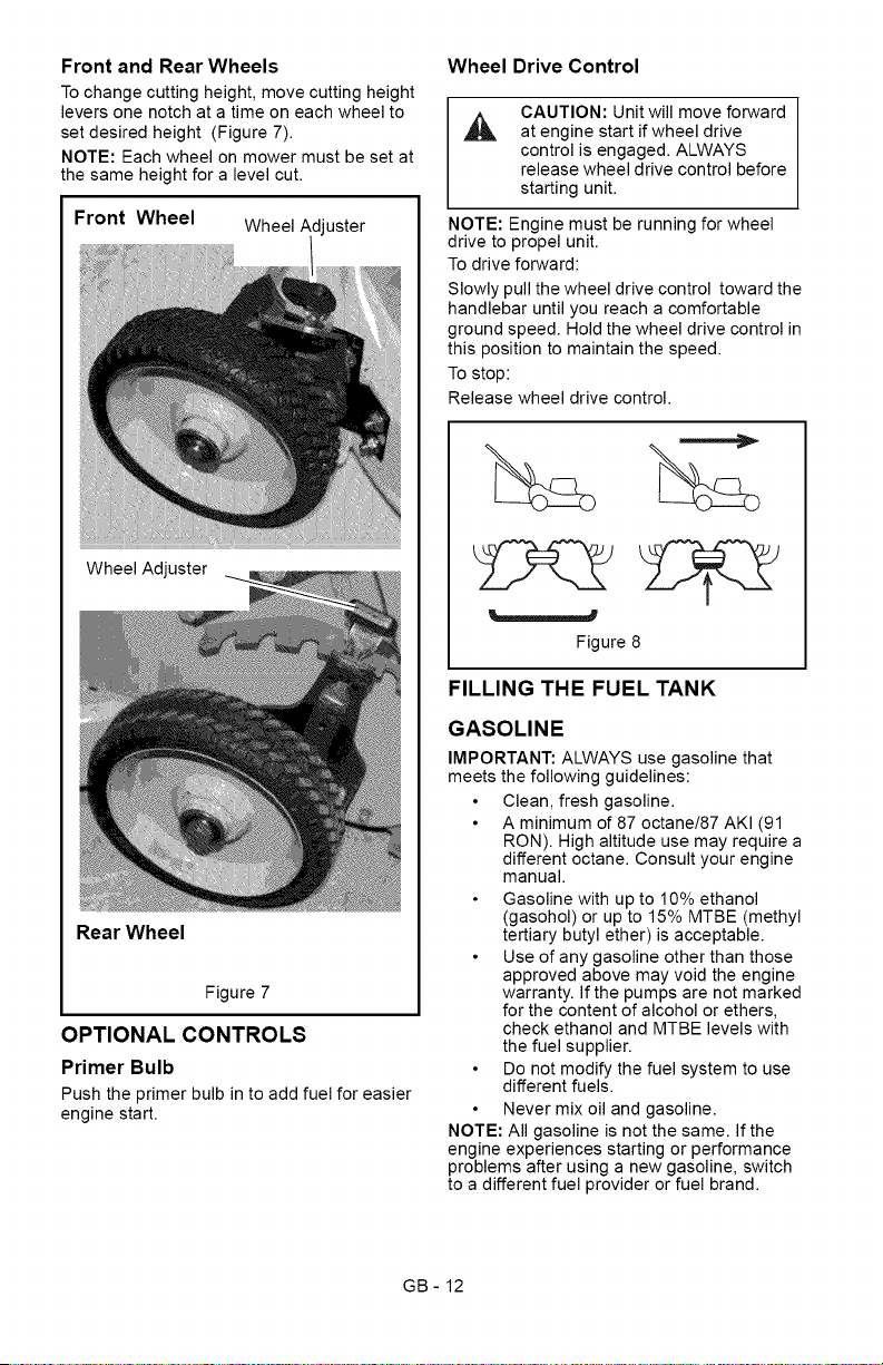
Front and Rear Wheels
To change cutting height, move cutting height
levers one notch at a time on each wheel to
set desired height (Figure 7).
NOTE: Each wheel on mower must be set at
the same height for a level cut.
Front Wheel Wheel Adjuster
Wheel Ad
Rear Wheel
Figure 7
OPTIONAL CONTROLS
Primer Bulb
Push the primer bulb in to add fuel for easier
engine start.
Wheel Drive Control
CAUTION: Unit will move forward
at engine start if wheel drive
control is engaged. ALWAYS
release wheel drive control before
starting unit.
NOTE: Engine must be running for wheel
drive to propel unit.
To drive forward:
Slowly pull the wheel drive control toward the
handlebar until you reach a comfortable
ground speed. Hold the wheel drive control in
this position to maintain the speed.
To stop:
Release wheel drive control.
Figure 8
FILLING THE FUEL TANK
GASOLINE
IMPORTANT: ALWAYS use gasoline that
meets the following guidelines:
Clean, fresh gasoline.
A minimum of 87 octane/87 AKI (91
IRON). High altitude use may require a
different octane. Consult your engine
manual.
Gasoline with up to 10% ethanol
(gasohol) or up to 15% MTBE (methyl
tertiary butyl ether) is acceptable.
Use of any gasoline other than those
approved above may void the engine
warranty. If the pumps are not marked
for the content of alcohol or ethers,
check ethanol and MTBE levels with
the fuel supplier.
Do not modify the fuel system to use
different fuels.
Never mix oil and gasoline.
NOTE: All gasoline is not the same. If the
engine experiences starting or performance
problems after using a new gasoline, switch
to a different fuel provider or fuel brand.
GB- 12
IMPORTANT:Excessivelyoxygenatedor
reformulatedfuels(fuelsblendedwith
alcoholsorethers)candamagethefuel
systemorcauseperformanceproblems.If
anyundesirableoperatingproblemsoccur,
useagasolinewithalowerpercentageof
alcoholorether.
Fuel Stabilizer
Gasoline left in the fuel system for extended
periods without a stabilizer will deteriorate,
resulting in gum deposits in the system.
These deposits can damage the carburetor
and the fuel hoses, filter and tank. Prevent
deposits from forming in the fuel system
during storage by adding a quality fuel
stabilizer to the fuel. Follow the
recommended mix ratio found on the fuel
stabilizer container.
To add fuel to fuel tank:
1. Put unit in open or well-ventilated area.
2. Stop engine and allow to cool.
3. Clean fuel cap and surrounding area.
4. Remove cap.
IMPORTANT: See engine manual for correct
type and grade of fuel.
5. Fill fuel tank to within 1/4 in. (0.63 cm)
below bottom of filler neck with unleaded
gasoline. See SPECIFICATIONS on
page 25.
6. Replace fuel cap and tighten.
7. ALWAYS clean any spilled fuel.
MOWER SET-UP
CAUTION: DO NOT operate
mower unless either side
discharge cover or side discharge
deflector is installed. Thrown
objects may cause damage or
injury. Never operate unit with rear
door open unless grass bag is in
place.
CAUTION: If clogs or obstruction
prevents grass flow, release
engine/blade control and
disconnect spark plug wire before
attempting to clear away any
clogs.
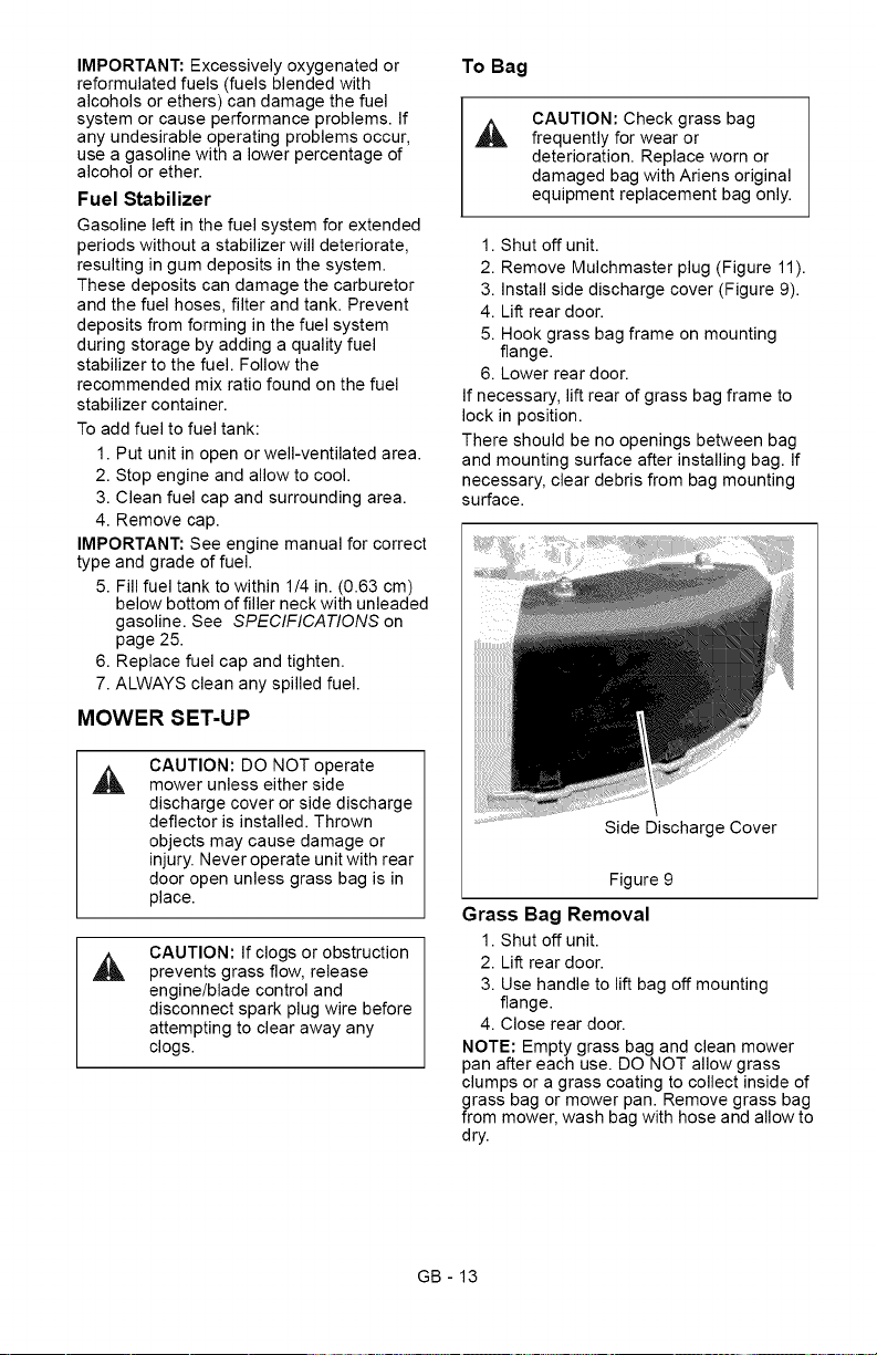
To Bag
CAUTION: Check grass bag
frequently for wear or
deterioration. Replace worn or
damaged bag with Ariens original
equipment replacement bag only.
1. Shut off unit.
2. Remove Mulchmaster plug (Figure 11).
3. Install side discharge cover (Figure 9).
4. Lift rear door.
5. Hook grass bag frame on mounting
flange.
6. Lower rear door.
If necessary, lift rear of grass bag frame to
lock in position.
There should be no openings between bag
and mounting surface after installing bag. If
necessary, clear debris from bag mounting
surface.
Side Discharge Cover
Figure 9
Grass Bag Removal
1. Shut off unit.
2. Lift rear door.
3. Use handle to lift bag off mounting
flange.
4. Close rear door.
NOTE: Empty grass bag and clean mower
pan after each use. DO NOT allow grass
clumps or a grass coating to collect inside of
grass bag or mower pan. Remove grass bag
from mower, wash bag with hose and allow to
dry.
GB - 13
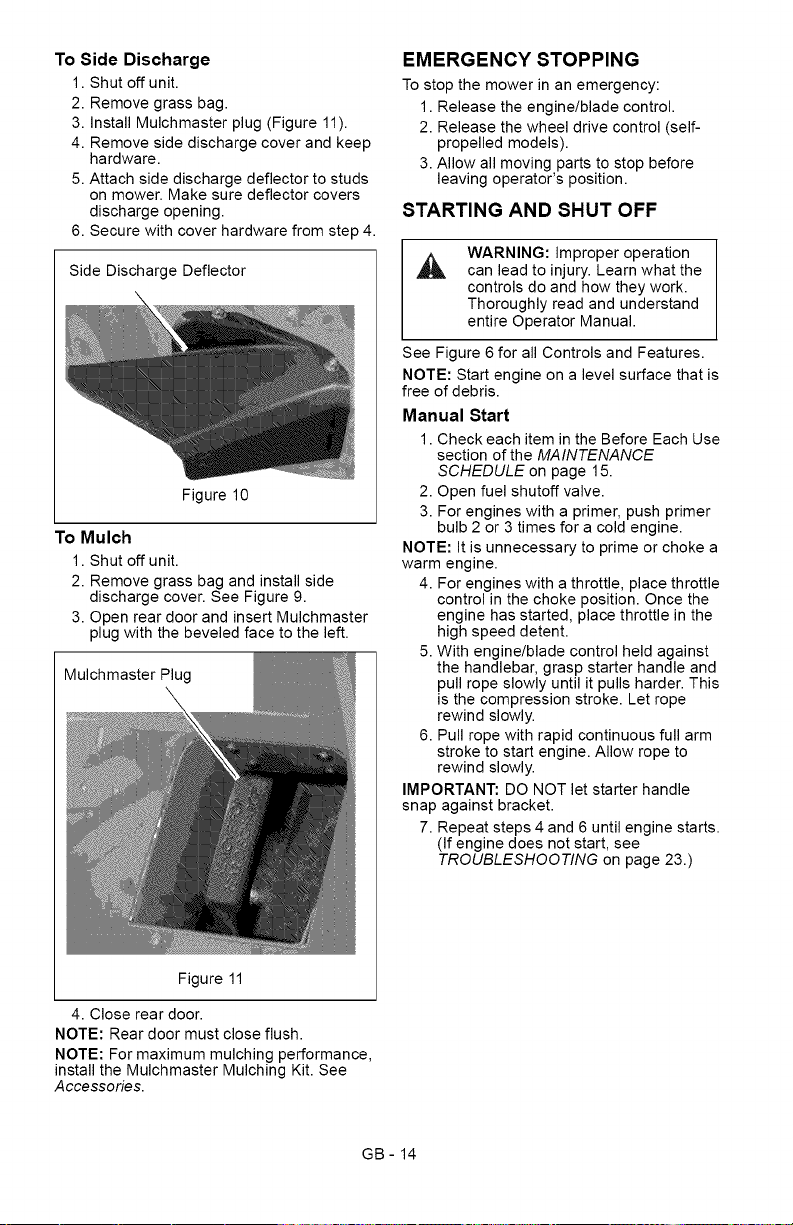
To Side Discharge
1. Shut off unit.
2. Remove grass bag.
3. Install Mulchmaster plug (Figure 11).
4. Remove side discharge cover and keep
hardware.
5. Attach side discharge deflector to studs
on mower. Make sure deflector covers
discharge opening.
6. Secure with cover hardware from step 4.
Side Discharge Deflector
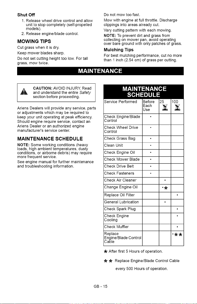
To Mulch
Figure 10
1. Shut off unit.
2. Remove grass bag and install side
discharge cover. See Figure 9.
3. Open rear door and insert Mulchmaster
plug with the beveled face to the left.
Mulchmaster Plug
Figure 11
4. Close rear door.
NOTE: Rear door must close flush.
NOTE: For maximum mulching performance,
install the Mulchmaster Mulching Kit. See
Accessories.
EMERGENCY STOPPING
To stop the mower in an emergency:
1. Release the engine/blade control.
2. Release the wheel drive control (self-
propelled models).
3. Allow all moving parts to stop before
leaving operator's position.
STARTING AND SHUT OFF
WARNING: Improper operation
can lead to injury. Learn what the
controls do and how they work.
Thoroughly read and understand
entire Operator Manual.
See Figure 6 for all Controls and Features.
NOTE: Start engine on a level surface that is
free of debris.
Manual Start
1. Check each item in the Before Each Use
section of the MAINTENANCE
SCHEDULE on page 15.
2. Open fuel shutoff valve.
3. For engines with a primer, push primer
bulb 2 or 3 times for a cold engine.
NOTE: It is unnecessary to prime or choke a
warm engine.
4. For engines with a throttle, place throttle
control in the choke position. Once the
engine has started, place throttle in the
high speed detent.
5. With engine/blade control held against
the handlebar, grasp starter handle and
pull rope slowly until it pulls harder. This
is the compression stroke. Let rope
rewind slowly.
6. Pull rope with rapid continuous full arm
stroke to start engine. Allow rope to
rewind slowly.
IMPORTANT: DO NOT let starter handle
snap against bracket.
7. Repeat steps 4 and 6 until engine starts.
(If engine does not start, see
TROUBLESHOOTING on page 23.)
GB- 14
Shut Off
1. Release wheel drive control and allow
unit to stop completely (self-propelled
models).
2. Release engine/blade control.
MOWING TIPS
Cut grass when it is dry.
Keep mower blades sharp.
Do not set cutting height too low. For tall
grass, mow twice.
Do not mow too fast.
Mow with engine at full throttle. Discharge
clippings into areas already cut.
Vary cutting pattern with each mowing.
NOTE: To prevent dirt and grass from
collecting on mower pan, avoid operating
over bare ground with only patches of grass.
Mulching Tips
For best mulching performance, cut no more
than 1 inch (2.54 cm) of grass per cutting.
CAUTION: AVOID INJURY. Read
and understand the entire Safety
section before proceeding.
Ariens Dealers will provide any service, parts
or adjustments which may be required to
keep your unit operating at peak efficiency.
Should engine require service, contact an
Ariens Dealer or an authorized engine
manufacturer's service center.
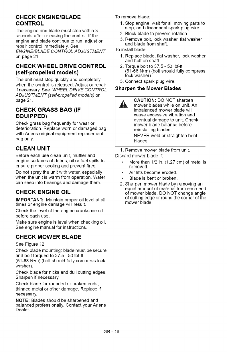
MAINTENANCE SCHEDULE
NOTE: Some working conditions (heavy
loads, high ambient temperatures, dusty
conditions, or airborne debris) may require
more frequent service.
See engine manual for further maintenance
and troubleshooting information.
Service Performed
Check Engine/Blade
Control
Check Wheel Drive
Control
Check Grass Bag
Clean Unit
Check Engine Oil
Check Mower Blade
Check Drive Belt
Check Fasteners
Check Air Cleaner
Change Engine Oil
Replace Oil Filter
General Lubrication
Check Spark Plug
Check Engine
Cooling
Check Muffler
Replace
Engine/Blade Control
Cable
After first 5 Hours of operation.
_ Replace Engine/Blade Control Cable
every 500 Hours of operation.
GB- 15
CHECK ENGINE/BLADE
CONTROL
The engine and blade must stop within 3
seconds after releasing the control. If the
engine and blade continue to run, adjust or
repair control immediately. See
ENGINE/BLADE CONTROL ADJUSTMENT
on page 21.
CHECK WHEEL DRIVE CONTROL
(self-propelled models)
The unit must stop quickly and completely
when the control is released. Adjust or repair
if necessary. See WHEEL DRIVE CONTROL
ADJUSTMENT (self-propelled models) on
page 21.
CHECK GRASS BAG (IF
EQUIPPED)
Check grass bag frequently for wear or
deterioration. Replace worn or damaged bag
with Ariens original equipment replacement
bag only.
CLEAN UNIT
Before each use clean unit, muffler and
engine surfaces of debris, oil or fuel spills to
ensure proper cooling and prevent fires.
Do not spray the unit with water, especially
when the unit is warm from operation. Water
can seep into bearings and damage them.
CHECK ENGINE OIL
IMPORTANT: Maintain proper oil level at all
times or engine damage will result.
Check the level of the engine crankcase oil
before each use.
Make sure engine is level when checking oil.
See engine manual for instructions.
CHECK MOWER BLADE
See Figure 12.
Check blade mounting: blade must be secure
and bolt torqued to 37.5 - 50 Ibf-ft
(51-68 N°m) (bolt should fully compress lock
washer).
Check blade for nicks and dull cutting edges.
Sharpen if necessary.
Check blade for rounded or broken ends,
thinned metal or other damage. Replace if
necessary.
NOTE: Blades should be sharpened and
balanced professionally. Contact your Ariens
Dealer.
To remove blade:
1. Stop engine, wait for all moving parts to
stop, and disconnect spark plug wire.
2. Block blade to prevent rotation.
3. Remove bolt, lock washer, flat washer
and blade from shaft.
To install blade:
1. Replace blade, flat washer, lock washer
and bolt on shaft.
2. Torque bolt to 37.5 - 50 Ibf-ft
(51-68 N°m) (bolt should fully compress
lock washer).
3. Connect spark plug wire.
Sharpen the Mower Blades
CAUTION: DO NOT sharpen
mower blades while on unit. An
imbalanced mower blade will
cause excessive vibration and
eventual damage to unit. Check
mower blade balance before
reinstalling blades.
NEVER weld or straighten bent
blades.
1. Remove mower blade from unit.
Discard mower blade if:
More than 1/2 in. (1.27 cm) of metal is
removed.
Air lifts become eroded.
Blade is bent or broken.
2. Sharpen mower blade by removing an
equal amount of material from each end
of mower blade. DO NOT change angle
of cutting edge or round the corner of the
mower blade.
GB- 16
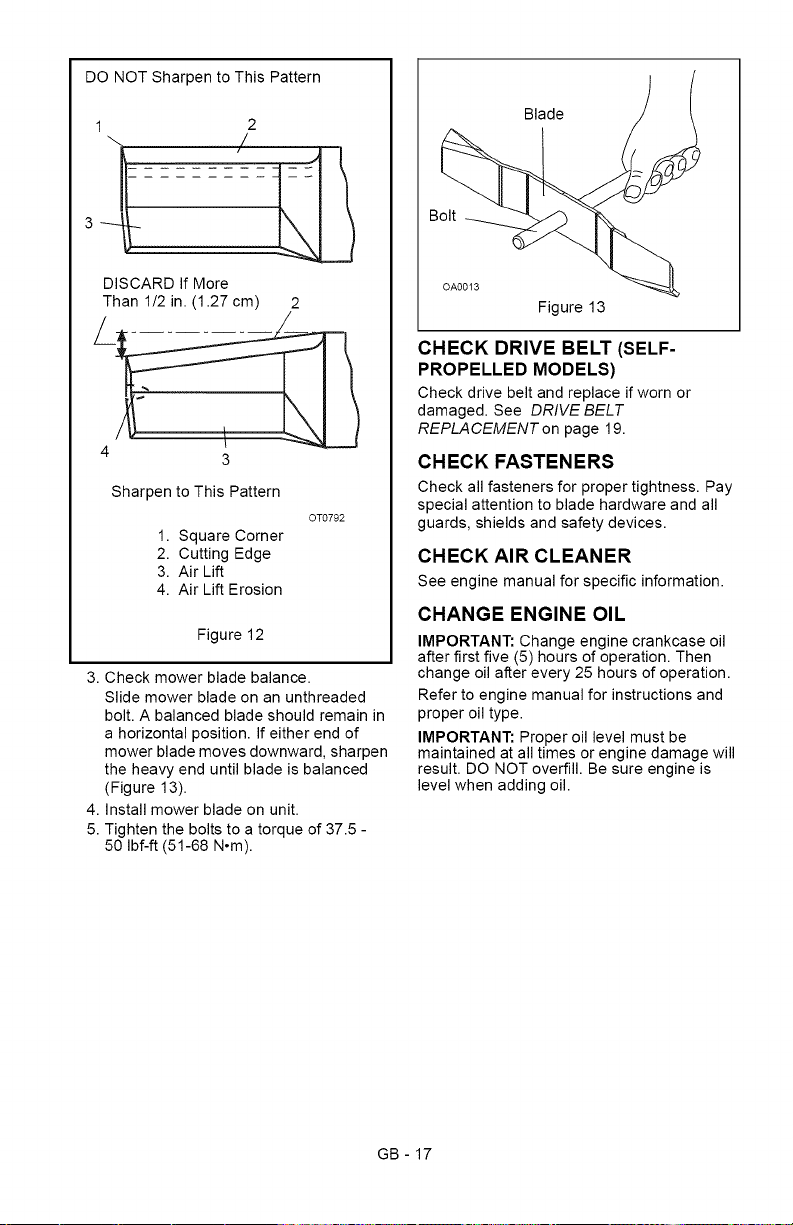
DONOTSharpentoThisPattern
1 2
DISCARDIfMore
Than1/2in.(1.27cm) 2
3
Sharpen to This Pattern
1. Square Corner
2. Cutting Edge
3. Air Lift
4. Air Lift Erosion
OT0792
Figure 12
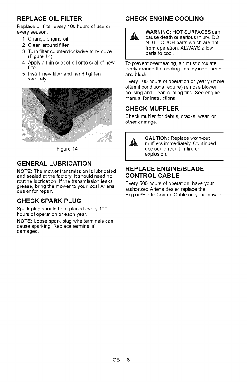
3. Check mower blade balance.
Slide mower blade on an unthreaded
bolt. A balanced blade should remain in
a horizontal position. If either end of
mower blade moves downward, sharpen
the heavy end until blade is balanced
(Figure 13).
4. Install mower blade on unit.
5. Tighten the bolts to a torque of 37.5 -
50 Ibf-ft (51-68 N°m).
Blade
Bolt
Figure 13
CHECK DRIVE BELT (SELF-
PROPELLED MODELS)
Check drive belt and replace if worn or
damaged. See DRIVE BELT
REPLA CEMENT on page 19.
CHECK FASTENERS
Check all fasteners for proper tightness. Pay
special attention to blade hardware and all
guards, shields and safety devices.
CHECK AIR CLEANER
See engine manual for specific information.
CHANGE ENGINE OIL
IMPORTANT: Change engine crankcase oil
after first five (5) hours of operation. Then
change oil after every 25 hours of operation.
Refer to engine manual for instructions and
proper oil type.
IMPORTANT: Proper oil level must be
maintained at all times or engine damage will
result. DO NOT overfill. Be sure engine is
level when adding oil.
GB - 17
REPLACE OIL FILTER
Replace oil filter every 100 hours of use or
every season.
1. Change engine oil.
2. Clean around filter.
3. Turn filter counterclockwise to remove
(Figure 14).
4. Apply a thin coat of oil onto seal of new
filter.
5. Install new filter and hand tighten
securely.
Figure 14
GENERAL LUBRICATION
NOTE: The mower transmission is lubricated
and sealed at the factory. It should need no
routine lubrication. If the transmission leaks
grease, bring the mower to your local Ariens
dealer for repair.
CHECK SPARK PLUG
Spark plug should be replaced every 100
hours of operation or each year.
NOTE: Loose spark plug wire terminals can
cause sparking. Replace terminal if
damaged.
CHECK ENGINE COOLING
A
WARNING: HOT SURFACES can
cause death or serious injury. DO
NOT TOUCH parts which are hot
from operation. ALWAYS allow
parts to cool.
To prevent overheating, air must circulate
freely around the cooling fins, cylinder head
and block.
Every 100 hours of operation or yearly (more
often if conditions require) remove blower
housing and clean cooling fins. See engine
manual for instructions.
CHECK MUFFLER
Check muffler for debris, cracks, wear, or
other damage.
CAUTION: Replace worn-out
_L, mufflers immediately. Continued
use could result in fire or
explosion.
REPLACE ENGINE/BLADE
CONTROL CABLE
Every 500 hours of operation, have your
authorized Ariens dealer replace the
Engine/Blade Control Cable on your mower.
GB- 18
_o_l V_4_I m]V_4m_ll_l / _vj1:1_III__]
CAUTION: AVOID INJURY. Read
,_ and understand the entire Safety
section before proceeding.
SERVICE POSITION
Put unit into service position for easy access
to underneath the deck.
,&
CAUTION: Avoid fuel spills.
Follow steps below to help
prevent fuel spills. If fuel leaks
into air cleaner, replace air
cleaner. ALWAYS clean up any
spilled fuel.
1. Place unit on a flat, level surface.
2. Disconnect spark plug wire from spark
plug.
3. Remove fuel cap, place a piece of
plastic bag over the opening and tighten
cap securely.
4. Tip unit onto rightside.
Make sure unit is secure and will not tip
over.
IMPORTANT: Remove plastic from fuel cap
after unit is upright and service is complete.
DRIVE BELT REPLACEMENT
To remove drive belt:
1. Disconnect spark plug wire from spark
plug.
2. Remove transmission cover.
3. Disconnect idler return spring from idler
arm. See Figure 15.
4. Disconnect the wheel drive cable from
transmission mount, and then
disconnect drive cable spring from idler
arm.
5. Remove belt from transmission input
pulley and transmission idlers, and then
push the belt out through the belt
channel.
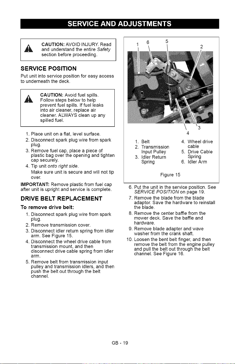
1. Belt
2. Transmission
Input Pulley
3. Idler Return
Spring
4. Wheel drive
cable
5. Drive Cable
Spring
6. Idler Arm
Figure 15
6. Put the unit in the service position. See
SERVICE POSITION on page 19.
7. Remove the blade from the blade
adaptor. Save the hardware to reinstall
the blade.
8. Remove the center baffle from the
mower deck. Save the baffle and
hardware.
9. Remove blade adapter and wave
washer from the crank shaft.
10. Loosen the bent belt finger, and then
remove the belt from the engine pulley
and pull the belt out through the belt
channel. See Figure 16.
GB - 19
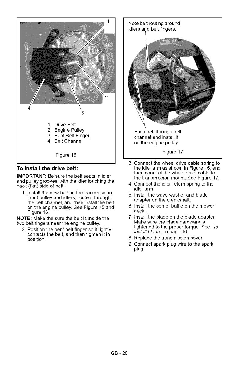
Notebeltroutingaround
idlersandbeltfingers.
1.DriveBelt
2. EnginePulley
3.BentBeltFinger
4. BeltChannel
Figure16
To install the drive belt:
IMPORTANT: Be sure the belt seats in idler
and pulley grooves with the idler touching the
back (flat) side of belt.
1. Install the new belt on the transmission
input pulley and idlers, route it through
the belt channel, and then install the belt
on the engine pulley. See Figure 15 and
Figure 16.
NOTE: Make the sure the belt is inside the
two belt fingers near the engine pulley.
2. Position the bent belt finger so it lightly
contacts the belt, and then tighten it in
position.
Push belt through belt
channel and install it
on the engine pulley.
Figure 17
3. Connect the wheel drive cable spring to
the idler arm as shown in Figure 15, and
then connect the wheel drive cable to
the transmission mount. See Figure 17.
4. Connect the idler return spring to the
idler arm.
5. Install the wave washer and blade
adapter on the crankshaft.
6. Install the center baffle on the mower
deck.
7. Install the blade on the blade adapter.
Make sure the blade hardware is
tightened to the proper torque. See To
install blade: on page 16.
8. Replace the transmission cover.
9. Connect spark plug wire to the spark
plug.
GB - 20
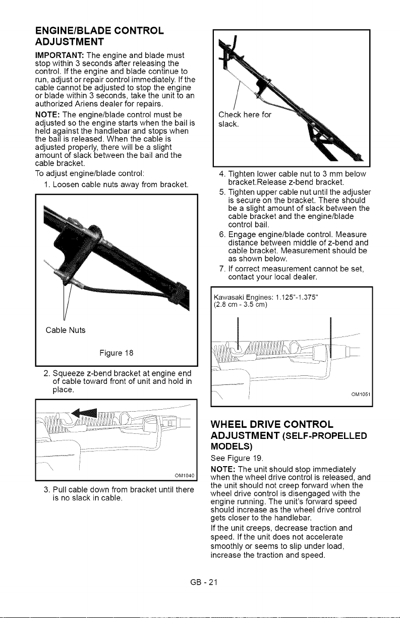
ENGINE/BLADE CONTROL
ADJUSTMENT
IMPORTANT: The engine and blade must
stop within 3 seconds after releasing the
control. If the engine and blade continue to
run, adjust or repair control immediately. If the
cable cannot be adjusted to stop the engine
or blade within 3 seconds, take the unit to an
authorized Ariens dealer for repairs.
NOTE: The engine/blade control must be
adjusted so the engine starts when the bail is
held against the handlebar and stops when
the bail is released. When the cable is
adjusted properly, there will be a slight
amount of slack between the bail and the
cable bracket.
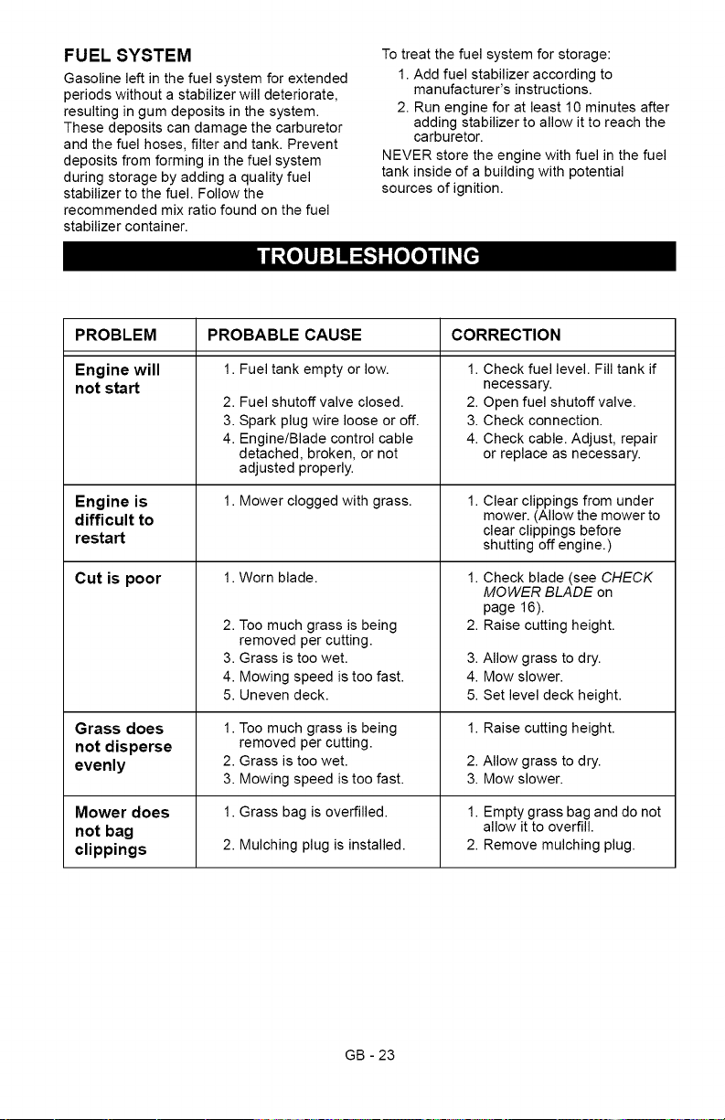
To adjust engine/blade control:
1. Loosen cable nuts away from bracket.
Cable Nuts
Figure 18
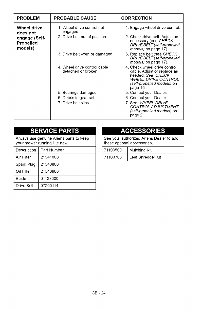
2. Squeeze z-bend bracket at engine end
of cable toward front of unit and hold in
place.
f................
...... j
I
\ J
OM1040
3. Pull cable down from bracket until there
is no slack in cable.
Check here for
slack.
4. Tighten lower cable nut to 3 mm below
bracket.Release z-bend bracket.
5. Tighten upper cable nut until the adjuster
is secure on the bracket. There should
be a slight amount of slack between the
cable bracket and the engine/blade
control bail.
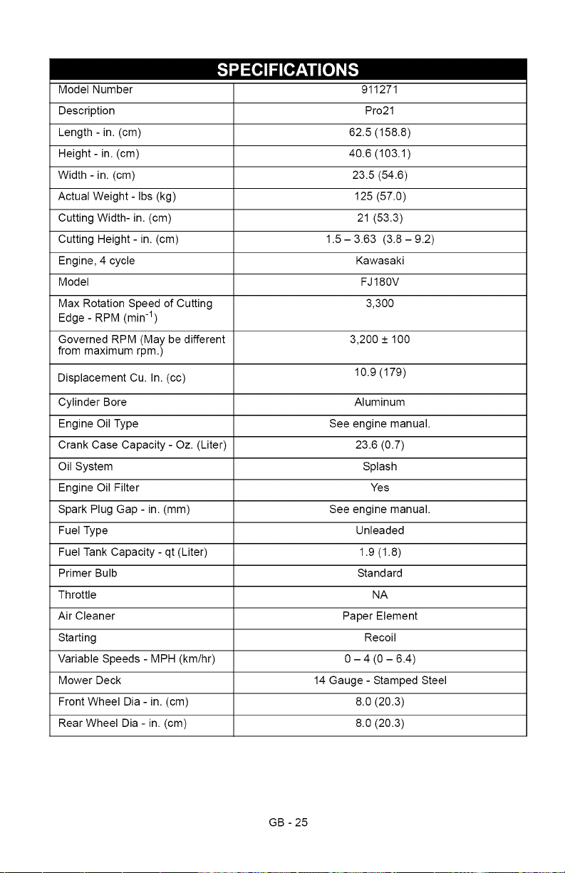
6. Engage engine/blade control. Measure
distance between middle of z-bend and
cable bracket. Measurement should be
as shown below.
7. If correct measurement cannot be set,
contact your local dealer.
Kawasaki Engines: 1.125"-1.375"
(2.8 cm - 3.5 cm)
........... i ......................
-\ i
0M1051
WHEEL DRIVE CONTROL
ADJUSTMENT (SELF-PROPELLED
MODELS)
See Figure 19.
NOTE: The unit should stop immediately
when the wheel drive control is released, and
the unit should not creep forward when the
wheel drive control is disengaged with the
engine running. The unit's forward speed
should increase as the wheel drive control
gets closer to the handlebar.
If the unit creeps, decrease traction and
speed. If the unit does not accelerate
smoothly or seems to slip under load,
increase the traction and speed.
GB - 21

NOTE:Beforeadjustingthewheeldrive
cable,firstmakesuretheareaaroundthe
drivecomponentsisfreeofdirtordebristhat
couldpreventthetransmissionfromengaging
ordisengagingproperly,andthenmakesure
thereturnspringisconnectedproperlyto
idlerarm.
Adjustthewheeldrivebyadjustingthecable
onthehandlebar.
IMPORTANT:DONOTadjustthecableso
thetransmissiondoesnotreturntoneutral
andstoptheunitwhenthecontrolbailis
released.
Check the adjustment
1. Start the engine and slowly squeeze the
wheel drive control against the
handlebar and then release the wheel
drive control.
2. The unit should move forward as you
squeeze the wheel drive control and
then stop immediately and not "creep"
slowly forward when you release it.
To adjust:
1. Move the wheel drive cable adjuster up
or down the handlebar. See Figure 19.
To increase traction and speed, move
the cable adjuster down the handlebar.
To decrease traction and speed, move
the cable adjuster up the handlebar.
2. Check the adjustment and readjust as
needed.
Cable Adjuster
Figure 19
CAUTION: AVOID INJURY. Read
and understand the entire Safety
section before proceeding.
IMPORTANT: NEVER spray unit with high-
pressure water or store unit outdoors. Store
mower in a cool, dry, protected location.
Cleaning
Allow unit to cool. Clean unit thoroughly with
mild soap and low pressure water. Brush off
dirt and debris from all surfaces. Touch up all
scratched surfaces to prevent rust. Matching
touch-up paint is available from your Ariens
Dealer. Do not use abrasives, solvents, or
harsh cleaners.
Inspection
Inspect mower and repair or replace worn or
damaged parts to avoid delays when
beginning use again.
Regularly check all hardware and keep
fasteners tight. Know unit is in safe working
condition.
Grass Bag
Wash out grass bag and allow to dry before
storage. Grass bag may be stored in position
on mower.
Engine
When storing unit for extended periods of
time, remove all fuel from tank and carburetor
(run dry). Refer to engine manual.
GB - 22
FUEL SYSTEM
Gasoline left in the fuel system for extended
periods without a stabilizer will deteriorate,
resulting in gum deposits in the system.
These deposits can damage the carburetor
and the fuel hoses, filter and tank. Prevent
deposits from forming in the fuel system
during storage by adding a quality fuel
stabilizer to the fuel. Follow the
recommended mix ratio found on the fuel
stabilizer container.
To treat the fuel system for storage:
1. Add fuel stabilizer according to
manufacturer's instructions.
2. Run engine for at least 10 minutes after
adding stabilizer to allow it to reach the
carburetor.
NEVER store the engine with fuel in the fuel
tank inside of a building with potential
sources of ignition.
/| _Toll]_'_[oIo)_
PROBLEM
Engine will
not start
Engine is
difficult to
restart
Cut is poor
Grass does
not disperse
evenly
Mower does
not bag
clippings
PROBABLE CAUSE CORRECTION
1. Fuel tank empty or low.
2. Fuel shutoff valve closed.
3. Spark plug wire loose or off.
4. Engine/Blade control cable
detached, broken, or not
adjusted properly.
1. Mower clogged with grass.
1. Worn blade.
2. Too much grass is being
removed per cutting.
3. Grass is too wet.
4. Mowing speed is too fast.
5. Uneven deck.
1. Too much grass is being
removed per cutting.
2. Grass is too wet.
3. Mowing speed is too fast.
1. Grass bag is overfilled.
2. Mulching plug is installed.
1. Check fuel level. Fill tank if
necessary.
2. Open fuel shutoff valve.
3. Check connection.
4. Check cable. Adjust, repair
or replace as necessary.
Clear clippings from under
mower. (Allow the mower to
clear clippings before
shutting off engine.)
1. Check blade (see CHECK
MOWER BLADE on
page 16).
2. Raise cutting height.
3. Allow grass to dry.
4. Mow slower.
5. Set level deck height.
1. Raise cutting height.
2. Allow grass to dry.
3. Mow slower.
1. Empty grass bag and do not
allow it to overfill.
2. Remove mulching plug.
GB - 23
PROBLEM PROBABLE CAUSE CORRECTION
Wheel drive
does not
engage (Self-
Propelled
models)
1. Wheel drive control not
engaged.
2. Drive belt out of position.
3. Drive belt worn or damaged.
4. Wheel drive control cable
detached or broken.
5. Bearings damaged.
6. Debris in gear set.
7. Drive belt slips.
1. Engage wheel drive control.
2. Check drive belt. Adjust as
necessary (see CHECK
DRIVE BELT (self-propelled
models) on page 17).
3. Replace belt (see CHECK
DRIVE BELT (self-propelled
models) on page 17).
4. Check wheel drive control
cable. Adjust or replace as
needed. See CHECK
WHEEL DRIVE CONTROL
(self-propelled models) on
page 16.
5. Contact your Dealer.
6. Contact your Dealer.
7. See WHEEL DRIVE
CONTROL ADJUSTMENT
(self-propelled models) on
page 21.
Always use genuine Ariens parts to keep
your mower running like new.
Description Part Number
Air Filter 21541000
Spark Plug 21540800
Oil Filter 21540900
Blade 01137000
Drive Belt 07200114
See your authorized Ariens Dealer to add
these optional accessories.
71103500 Mulching Kit
71103700 Leaf Shredder Kit
GB - 24
___o_,,,_
Model Number 911271
Description Pro21
Length - in. (cm) 62.5 (158.8)
Height- in. (cm) 40.6 (103.1)
Width - in. (cm) 23.5 (54.6)
Actual Weight- Ibs (kg) 125 (57.0)
Cutting Width- in. (cm) 21 (53.3)
Cutting Height - in. (cm) 1.5 - 3.63 (3.8 - 9.2)
Engine, 4 cycle Kawasaki
Model FJ 180V
Max Rotation Speed of Cutting 3,300
Edge - RPM (min -1)
Governed RPM (May be different 3,200 + 100
from maximum rpm.)
Displacement Cu. In. (cc) 10.9 (179)
Cylinder Bore Aluminum
Engine Oil Type See engine manual.
Crank Case Capacity - Oz. (Liter) 23.6 (0.7)
Oil System Splash
Engine Oil Filter Yes
Spark Plug Gap - in. (mm) See engine manual.
Fuel Type Unleaded
Fuel Tank Capacity - qt (Liter) 1.9 (1.8)
Primer Bulb Standard
Throttle NA
Air Cleaner Paper Element
Starting Recoil
Variable Speeds - MPH (km/hr) 0 - 4 (0 - 6.4)
Mower Deck 14 Gauge - Stamped Steel
Front Wheel Dia - in. (cm) 8.0 (20.3)
Rear Wheel Dia - in. (cm) 8.0 (20.3)
GB - 25

Two-Year Limited Lawn
and Garden Warranty
This warranty statement applies only to 21-Inch Walk Behind Lawn Mowers, Wide Area
Walks, AMP Wide Area Walks, Tillers, String Trimmers, Log Splitters, Edgers and Power
Brushes
Ariens Company (Ariens) warrants to the original purchaser that Ariens and Gravely brand consumer
products manufactured and sold by Ariens will be free from defects in material and workmanship for a period
of two years after the date of purchase. An authorized Ariens dealer (Ariens brand products) or Gravely
dealer (Gravely brand products) will repair any defect in material or workmanship, and repair or replace any
defective part, subject to the conditions, limitations and exclusions set forth herein. Such repair or
replacement will be free of charge (labor and parts) to the original purchaser except as noted below.
Two-Year Limited Warranty on AMP TM Series Battery Packs and Subassembfies
The battery pack and/or battery subassemblies on AMP series electric mowers is/are warranted to the
original purchaser for two years from the date of purchase. Ariens will replace, free of charge to the
original purchaser, any battery pack and/or battery subassembly that fails due to defect in material or
workmanship for one year after the date of purchase. For the next 12 months, Ariens will cover the pro-
rated cost of replacing a battery pack and/or battery subassembly that fails due to defect in material or
workmanship. This warranty does not apply to battery packs or battery subassemblies that fail due to
accident, neglect, abuse, improper maintenance, improper storage or improper charging procedures.
One-Year Limited Warranty on Professional/Commercial 21-inch Walk-Behind Lawn
Mowers
21-inch walk-behind lawn mowers labeled or designated by Ariens as a Professional/Commercial prod-
uct put to any business use, agricultural, commercial, or industrial, are warranted to the original pur-
chaser to be free from defects in material and workmanship for a period of one year after the date of
purchase.
90-Day Limited Warranty on Service Parts and Accessories
Genuine Ariens or Gravely brand service parts and accessories are warranted to be free from defects
in material and workmanship for a period of 90 days after the date of purchase. An authorized Ariens or
Gravely dealer will repair or replace any such part or accessory free of charge, except for labor, during
that period.
Except for 21-inch walk-behind lawn mowers labeled or designated by Ariens as a Professional/Commercial
product, the duration of all warranties herein applies only if the product is put to personal use around a
household or residence. If the product is put to any business use, agricultural, commercial, or industrial, then
the duration of these warranties shall be 90 days after the date of purchase. If any product is rented or
leased, then the duration of these warranties shall be 90 days after the date of purchase.
Exceptions, Limitations, Exclusions
Customer Responsibilities
Register the product immediately at the time of sale. If the dealer does not register the product, the
customer must complete the product registration card in the literature package and return it to the Ariens
Company, or register the unit online at www.ariens.com or www.gravely.com.
To obtain warranty service, the original purchaser must:
Perform the maintenance and minor adjustments explained in the owner's manual.
Promptly notify Ariens or an authorized Ariens or Gravely service representative of the need for
warranty service.
Transport the product to and from the place of warranty service.
Have the warranty service performed by an authorized Ariens or Gravely service representative.
ARIENS COMPANY
GRAVELY® I STENSC_ I LQCKEC_ I NATtQNAL® I BYNORM(_ I EVERRIDEC_ I GREAT DANE c_ Con L&G 2010
27
To find an Ariens or Gravely authorized service representative, contact Ariens at:
655 W. Ryan Street
Brillion, WI 54110
(920) 756- 2141
www.ariens.com
www.gravely.com
Exceptions and Limitations
Batteries are warranted only for a period of 12 months after date of purchase, on a prorated basis. For
the first 90 days of the warranty period, a defective battery will be replaced free of charge. If the
applicable warranty period is more than 90 days, Ariens will cover the prorated cost of any defective
battery, for up to 12 months after the date of purchase. This battery limited warranty does not apply to
the battery packs on AMP series products.
Exclusions - Items Not Covered by This Warranty
Engines and engine accessories are covered only by the engine manufacturer's warranty and are not
covered by this warranty.
Parts that are not genuine Ariens or Gravely service parts are not covered by this warranty.
The following maintenance, service and replacement items are not covered by this warranty unless
they are noted in the Limitations section above: lubricants, spark plugs, oil, oil filters, air filters, fuel
filters, brake linings, brake arms, brake shoes, runners, scraper blades, shear bolts, mower blades,
mower vanes, tines, brushes, headlights, light bulbs, knives, cutters.
Any misuse, alteration, improper assembly, improper adjustment, neglect, or accident which requires
repair is not covered by this warranty.
This warranty applies only to products purchased in the United States (including Puerto Rico) and
Canada. In all other countries, contact place of purchase for warranty information.
Disclaimer
Ariens may from time to time change the design of its products. Nothing contained in this warranty shall be
construed as obligating Ariens to incorporate such design changes into previously manufactured products,
nor shall such changes be construed as an admission that previous designs were defective.
LIMITATION OF REMEDY AND DAMAGES
Ariens Company's liability under this warranty, and under any implied warranty that may exist, is limited to
repair of any defect in workmanship, and repair or replacement of any defective part. Ariens shall not be
liable for incidental, special, or consequential damages (including lost profits). Some states do not allow the
exclusion of incidental or consequential damages, so the above limitation or exclusion may not apply to you.
DISCLAIMER OF FURTHER WARRANTY
Ariens Company makes no warranty, express or implied, other than what is expressly made in this
warranty. If the law of your state provides that an implied warranty of merchantability, or an implied
warranty of fitness for particular purpose, or any other implied warranty, applies to Ariens Company,
then any such implied warranty is limited to the duration of this warranty. Some states do not allow
limitations on how long an implied warranty lasts, so the above limitation may not apply to you.
This warranty gives you specific legal rights, and you may also have other rights which
vary from state to state.
ARIENS COMPANY
GRAVELY® I STENSC_ I LOCKEC_ I NATIONAL® I BYNORM_ I EVERRIDEC_ I GREAT DANE c_ Con L&G 2010
28

Ariens Company
655 West Ryan Street
Brillion, WI 54110-1072
920-756-2141
Fax 920-756-2407
www.ariens.com
A WARNING A
The engine exhaust from this product
contains chemicals known to the State
of California to cause cancer, birth
defects or other reproductive harm.

Walk Behind Lawn Mower
Manual del propietario/operador
Models
911271 - Pro21
_II_ _ _ ESPA_IOL
01326702 3/10
Printed in USA
I1Eqi][_"
Seguridad ........................ 4
Montaje .......................... 9
Controles y caracteristicas ........ 11
Funcionamiento .................. 12
Mantenimiento ................... 17
Reparaciones y ajustes ........... 20
Almacenamiento ................. 24
Localizaci6n de averias ........... 25
Piezas de repuesto ............... 26
Accesorios ...................... 26
Especificaciones ................. 27
Garantia ........................ 28
limb/ _,_o_]_l
NON-ENGLISH MANUALS
Manuals in languages other than
,_ English may be obtained from
your Dealer. Visit your dealer or
www.ariens.com for a list of
languages available for your
equipment.
Manuals printed in languages
other than English are also
available as a free download on
our website:
http://www.ariens.com
MANUALES EN IDIOMAS
DIFERENTES DEL INGLES
Puede obtener manuales en
,_ idiomas diferentes del ingles en sudistribuidor. Visite a su distribuidor
o vaya a www.ariens.com para
obtener una lista de idiomas
disponibles para su equipo.
Tambien puede imprimir manuales
en idiomas diferentes del ingles
descargandolos gratuitamente de
nuestra pagina Web:
http://www.ariens.com
MANUELS NON ANGLAIS
Des manuels dans diff@entes
,_ langues sont disponibles chezvotre revendeur. Rendez-vous
chez votre revendeur ou allez sur
le site www.ariens.com pour
consulter la liste des langues
disponibles pour votre equipement.
Les manuels imprimes dans des
langues diff@entes de I'anglais
sont egalement disponibles en
telechargement gratuit sur notre
site Web :
http://www.ariens.com
EL MANUAL
Antes de utilizar la unidad, lea con atenci6n
yen su totalidad los manuales. El contenido
de los manuales le ayudara a entender las
instrucciones y los controles durante el
funcionamiento normal y el mantenimiento.
Todas las referencias a la izquierda, derecha,
delante o detras se dan desde la posici6n
del operador, orientado en la direcci6n de
marcha adelante.
MANTENIMIENTO Y PIEZAS DE
REPUESTO
AI pedir piezas de repuesto o al realizar
preguntas sobre reparaciones, tenga a mano
los nQmeros de modelo y de serie de la unidad
y del motor.
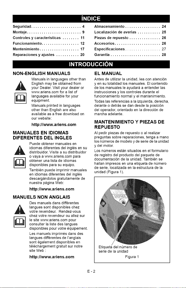
Los nQmeros estan situados en el formulario
de registro del producto del paquete de
documentaci6n de la unidad. Tambien se
hallan impresos en una etiqueta de nQmero
de serie, Iocalizada en la estructura de la
unidad (Figura 1).
Etiqueta del nQmero de
serie de la unidad
Figura 1
E-2
•AnoteaquilosnQmerosdemodeloyde
seriedelaunidad.
J
• Anote aqui los nQmeros de modelo y de
serie del motor:
J
REGISTRO DEL PRODUCTO
El concesionario Ariens debera registrar el
producto en el momento de la compra. El
registro del producto ayudara a la compaSia
a procesar las reclamaciones de garantia, asi
como a ponerse en contacto con usted con la
informaci6n de servicio mas reciente. Todas
las reclamaciones que cumplan los requisitos
durante el periodo de garantia limitada seran
aceptadas, independientemente de si se
devuelve o no la tarjeta de registro de
producto. Guarde una prueba de su compra si
no registra su unidad.
Nota para el cliente: Si el Concesionario no
registra el producto, rellene, firme y devuelva
la tarjeta de registro del producto a Ariens o
vaya a www.ariens.com en Intemet.
PIEZA8 DE REPUESTO NO
AUTORIZADAS
Utilice Qnicamente piezas de repuesto de
Ariens. La sustituci6n de cualquier pieza de
este vehiculo por otra que no sea una pieza
de repuesto autorizada por Ariens puede
afectar negativamente al rendimiento, la
durabilidad o la seguridad de la unidad, y
puede Ilegar a anular la garantia. Ariens
declina toda responsabilidad por daSos o
reclamaciones, ya sea a la garantia, daSos
materiales, lesiones o incluso la muerte,
provocados por el uso de piezas de repuesto
no autorizadas. Para Iocalizar su distribuidor
Ariens mas cercano, acuda a
www.ariens.com en Intemet.
ENTREGA DEL CONCESIONARIO
El concesionario debe:
1. Verificar que el montaje y todos los ajustes
se hayan realizado adecuadamente.
2. Rellenar la tarjeta de registro del
comprador original y enviarla de vuelta
a Ariens.
3. Explicar la politica de garantia limitada
de Ariens.
4. Explicar la lubricaci6n y el mantenimiento
recomendado. Asesorar al cliente sobre
los ajustes. Recordar al cliente que
cambie el aceite del carter del motor
4 ciclos tras las primeras cinco (5) horas
de funcionamiento.
5. Explicar al cliente los controles y el
funcionamiento de la unidad. Asesorar
al cliente sobre los ajustes. Comentarle
e insistirle sobre las reglas de
seguridad. Proporcionarle los Manuales
del propietario/operador, piezas de
repuesto y del motor. Aconsejarle que
los lea atentamente y los entienda.
CLAUSULA DE EXENCION DE
RESPONSABILIDAD
Ariens se reserva el derecho de abandonar la
fabricaci6n, realizar cambios y mejoras a sus
productos en cualquier momento, sin previo
aviso u obligaci6n. Las descripciones y
especificaciones contenidas en este manual
eran las vigentes en el momento de su
publicaci6n. Algunos equipamientos
descritos en este manual pueden ser
opcionales. Algunas ilustraciones pueden no
ser de aplicaci6n a su unidad.
E-3
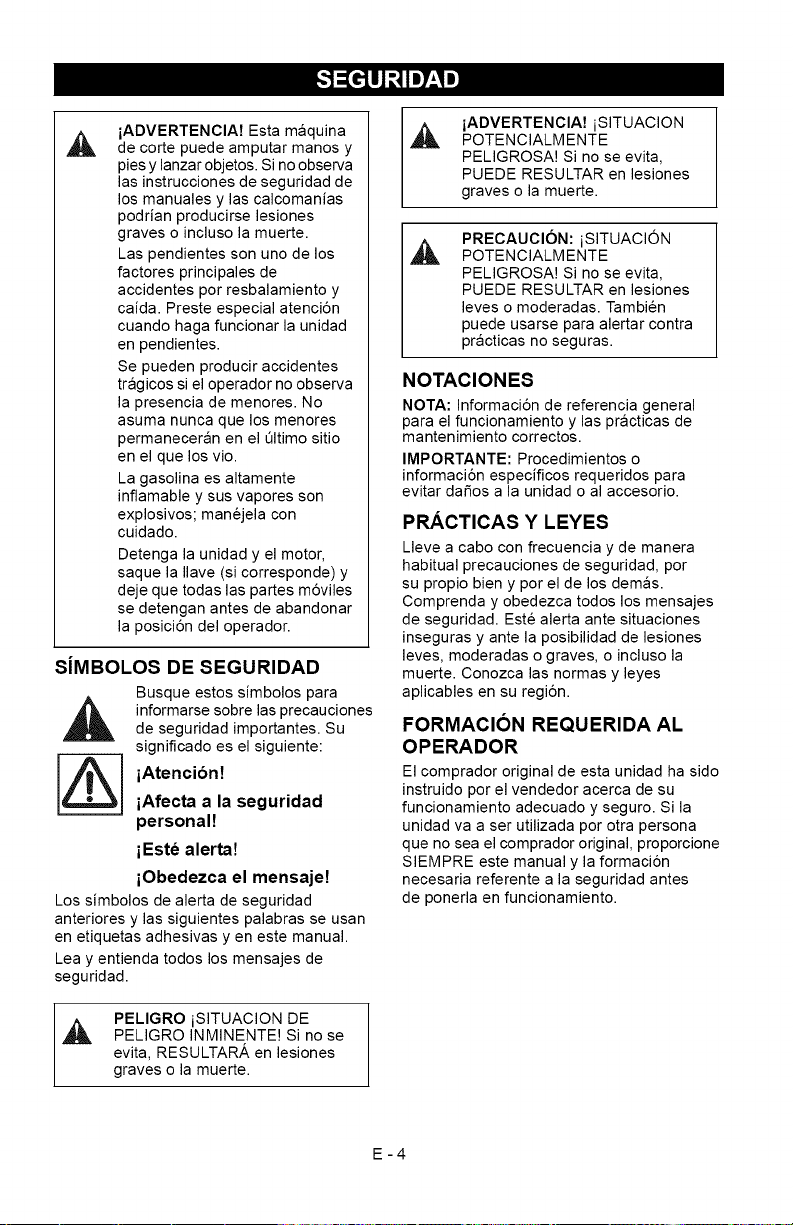
iADVERTENClA7Estamaquina
decortepuedeamputarmanosy
piesylanzarobjetos.Sinoobserva
lasinstruccionesdeseguridadde
losmanualesylascalcomanias
podrianproducirselesiones
gravesoinclusolamuerte.
Laspendientessonunodelos
factoresprincipalesde
accidentesporresbalamientoy
caida.PresteespecialatenciSn
cuandohagafuncionarlaunidad
enpendientes.
Sepuedenproduciraccidentes
tragicossieloperadornoobserva
lapresenciademenores.No
asumanuncaquelosmenores
permaneceranenelt31timositio
enelquelosvio.
Lagasolinaesaltamente
inflamableysusvaporesson
explosivos;manejelacon
cuidado.
Detengalaunidadyelmotor,
saquelaIlave(sicorresponde)y
dejequetodaslaspartesm6viles
sedetenganantes de abandonar
la posiciSn del operador.
S[MBOLOS DE SEGURIDAD
Busque estos simbolos para
informarse sobre las precauciones
de seguridad importantes. Su
significado es el siguiente:
iAtencibn!
iAfecta a la seguridad
personal!
iEste alerta!
iObedezca el mensaje!
Los simbolos de alerta de seguridad
anteriores y las siguientes palabras se usan
en etiquetas adhesivas y en este manual.
Lea y entienda todos los mensajes de
seguridad.
,&
PELIGRO iSITUACION DE
PELIGRO INMINENTE! Si no se
evita, RESULTAR,& en lesiones
graves o la muerte.
iADVERTENCIA7 iSITUACION
,_ POTENCIALMENTE
PELIGROSA! Si no se evita,
PUEDE RESULTAR en lesiones
graves o la muerte.
PRECAUCION: iSITUACION
POTENCIALMENTE
PELIGROSA! Si no se evita,
PUEDE RESULTAR en lesiones
leves o moderadas. Tambien
puede usarse para alertar contra
practicas no seguras.
NOTACIONES
NOTA: Informaci6n de referencia general
para el funcionamiento y las practicas de
mantenimiento correctos.
IMPORTANTE: Procedimientos o
informaci6n especificos requeridos para
evitar daSos a la unidad o al accesorio.
PRACTICAS Y LEYES
Lleve a cabo con frecuencia y de manera
habitual precauciones de seguridad, por
su propio bien y por el de los demas.
Comprenda y obedezca todos los mensajes
de seguridad. Este alerta ante situaciones
inseguras y ante la posibilidad de lesiones
leves, moderadas o graves, o incluso la
muerte. Conozca las normas y leyes
aplicables en su regi6n.
FORMACION REQUERIDA AL
OPERADOR
El comprador original de esta unidad ha sido
instruido por el vendedor acerca de su
funcionamiento adecuado y seguro. Si la
unidad va a ser utilizada por otra persona
que no sea el comprador original, proporcione
SIEMPRE este manual y la formaci6n
necesaria referente a la seguridad antes
de ponerla en funcionamiento.
E-4
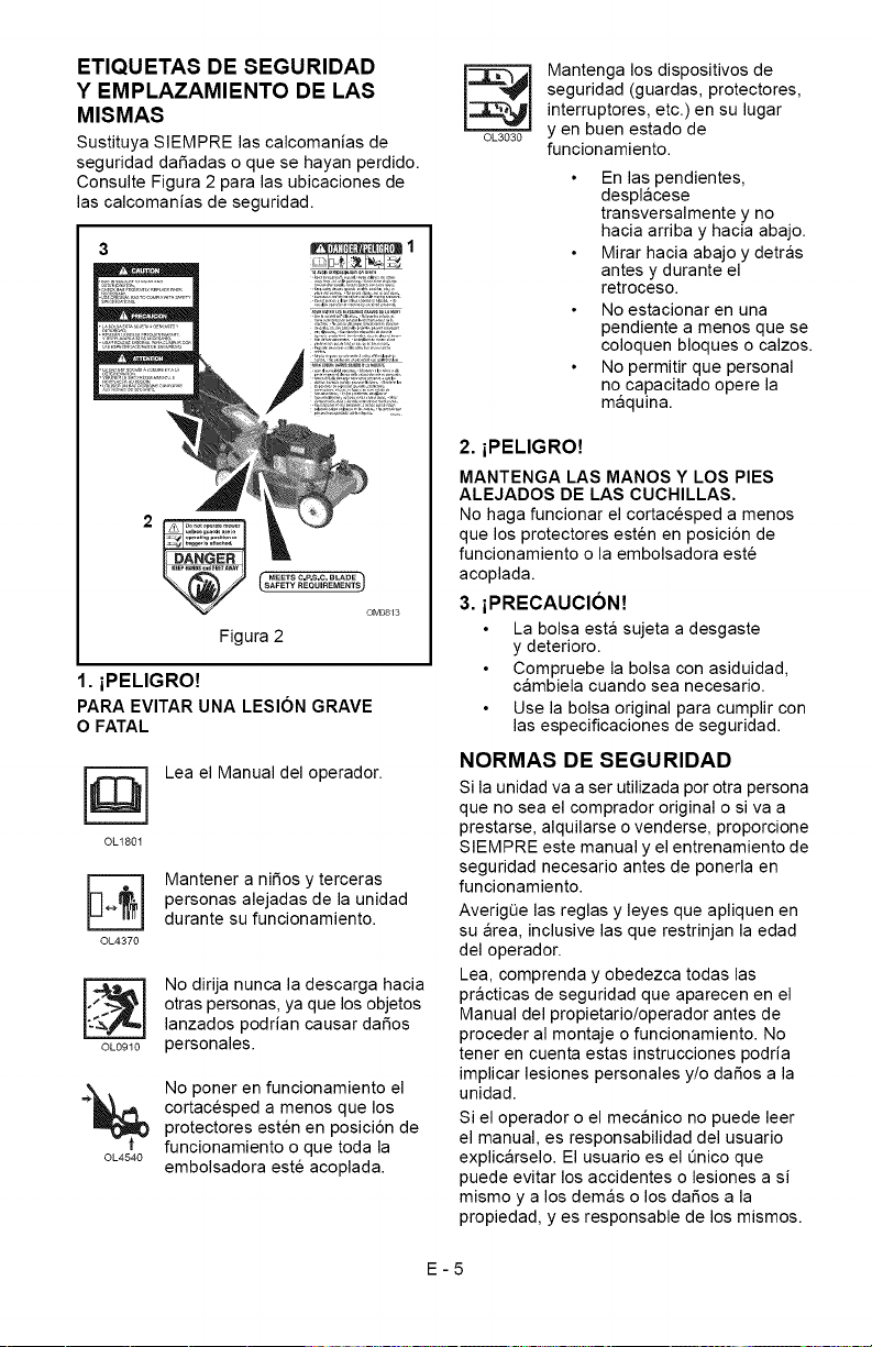
ETIQUETAS DE SEGURIDAD
Y EMPLAZAMIENTO DE LAS
MISMAS
Sustituya SIEMPRE las calcomanias de
seguridad dafiadas o que se hayan perdido.
Consulte Figura 2 para las ubicaciones de
las calcomanias de seguridad.
MEET S C.P,$,C, BLADE
OM0813
Figura 2
1. iPELIGRO!
PARA EVITAR UNA LESION GRAVE
O FATAL
OL180I
OL4370
Lea el Manual del operador.
Mantener a nifios y terceras
personas alejadas de la unidad
durante su funcionamiento.
OL0910
OL4540
No dirija nunca la descarga hacia
otras personas, ya que los objetos
lanzados podrian causar dafios
personales.
No poner en funcionamiento el
cortacesped a menos que los
protectores esten en posici6n de
funcionamiento o que toda la
embolsadora este acoplada.
OL3030
Mantenga los dispositivos de
seguridad (guardas, protectores,
interruptores, etc.) en su lugar
yen buen estado de
funcionamiento.
En las pendientes,
desplacese
transversalmente y no
hacia arriba y hacia abajo.
Mirar hacia abajo y detras
antes y durante el
retroceso.
No estacionar en una
pendiente a menos que se
coloquen bloques o calzos.
No permitir que personal
no capacitado opere la
maquina.
2. iPELIGRO!
MANTENGA LAS MANOS Y LOS PIES
ALEJADOS DE LAS CUCHILLAS.
No haga funcionar el cortacesped a menos
que los protectores esten en posici6n de
funcionamiento o la embolsadora este
acoplada.
3. iPRECAUCION!
La bolsa esta sujeta a desgaste
y deterioro.
Compruebe la bolsa con asiduidad,
cambiela cuando sea necesario.
Use la bolsa original para cumplir con
las especificaciones de seguridad.
NORMAS DESEGURIDAD
Si la unidad va a ser utilizada por otra persona
que no sea el comprador original o siva a
prestarse, alquilarse o venderse, proporcione
SIEMPRE este manual y el entrenamiento de
seguridad necesario antes de ponerla en
funcionamiento.
AverigQe las reglas y leyes que apliquen en
su area, inclusive las que restrinjan la edad
del operador.
Lea, comprenda y obedezca todas las
practicas de seguridad que aparecen en el
Manual del propietario/operador antes de
proceder al montaje o funcionamiento. No
tener en cuenta estas instrucciones podria
implicar lesiones personales y/o dafios a la
unidad.
Si el operador o el mecanico no puede leer
el manual, es responsabilidad del usuario
explicarselo. El usuario es el Qnico que
puede evitar los accidentes o lesiones a si
mismo y a los demas o los dafios a la
propiedad, yes responsable de los mismos.
E-5
RetireSIEMPRElaIlave(sidisponedeella)y
desconecteelcabledelabujiadeencendido
antesderealizarlaboresdemontaje.Un
arranquenointencionadodelmotorpodria
provocarlesionesgravesoinclusolamuerte.
Realiceunainspecci6ngeneraldelareade
trabajoydelaunidadparaentender:
elareadetrabajo
launidad
todaslascalcomaniasdeseguridad.
Limpieelareadetrabajodepiedras,ramas,
cablesyotrosobjetosextrafiosquepuedan
serrecogidosyarrojados.Sielcespedesta
alto,puedeocultarobjetos.
Conozcaelareadetrabajo.Tengacuidado
conlosagujeros,piedras,terrenoaccidentado
yotrospeligros.
Evitelosterrenosdesnivelados,zanjas
oterraplenesquepuedancausarqueel
operadorpierdaelcontroldelaunidad.
Cuandoopereencallesocurvas,este
SIEMPREatentoaltrafico.
Mantengaelareadetrabajolibrede
personas,nifiosyanimales.
Losnifiosdebenmantenersefueradelarea
detrabajoybajolasupervisi6natentadeun
adultoresponsable.
PongaSIEMPREenfuncionamientola
unidadcuandohayabuenavisibilidade
iluminaci6n.
NOcortecespedhQmedo.
AsegereseSIEMPREdesupropiaestabilidad
sobreelsuelo.Agarrefirmementeelmanillar.
Camine,nocorraNUNCA.
Lafunci6ndecontroldelmotor/ la cuchilla
del cortacesped detiene el motor y la cuchilla
en 3 segundos cuando el operador suelta el
manillar. Compruebe esta funci6n a menudo.
Si esta funci6n se estropea, desconecte el
cable de la bujia y ajQstelo o reparelo antes
de utilizar la unidad.
Solo los adultos formados pueden hacer
funcionar o mantener la unidad. La formaci6n
incluye el funcionamiento. El propietario es
responsable de formar a los usuarios.
NUNCA haga funcionar la unidad durante o
despues del consumo de medicaci6n, alcohol
o drogas. La unidad requiere su atenci6n
total yen perfecto estado de salud.
NUNCA permita que los nifios pongan en
funcionamiento ni realicen el mantenimiento
del cortacesped.
Mantenga las manos y los pies SIEMPRE
alejados de las piezas giratorias. Las piezas
giratorias pueden amputar miembros.
Mantener SIEMPRE las manos fuera del
alcance de los puntos de mordedura.
El humo del tubo de escape puede causar
lesiones graves o incluso la muerte. NO haga
funcionar el motor en un area cerrada.
Protejase SIEMPRE los ojos, la cara y el
cuerpo con el equipo de seguridad adecuado
y ropa protectora. Lleve calzado, guantes, un
gorro duro y, en los ojos, mascara o gafas de
seguridad con protectores laterales mientras
utiliza el cortacesped.
Use una protecci6n adecuada para los oidos.
NUNCA ponga en funcionamiento el
cortacesped descalzo, con sandalias o
zapatos de tela.
No Ileve NUNCA ropa suelta, joyas o cabello
largo suelto ya que pueden quedar atrapados
en las piezas giratorias.
Mantengase SIEMPRE alejado de la descarga
durante el funcionamiento de la unidad.
NUNCA dirija la descarga hacia terceros.
El operador es el responsable de la seguridad
de terceras personas.
NO toque las piezas calientes. Deje que se
enfrien.
Mantenga los dispositivos o las guardas
de seguridad en su sitio y funcionando
correctamente. NO modifique ni retire
NUNCA los dispositivos de seguridad.
Lea, comprenda y obedezca todas las
instrucciones en el manual yen la maquina
antes de arrancar. Debe comprender Io
siguiente:
C6mo utilizar todos los controles
Las funciones de todos los controles
C6mo PARAR en caso de emergencia
NO intente arrancar el motor hasta que no
se conozcan las funciones de los controles
y c6mo funcionan.
NO incline el cortacesped al arrancar.
AI arrancar el motor, los pies deben
mantenerse alejados.
NO arranque ni utilice el cortacesped sin tener
instalada la cubierta de descarga lateral o el
deflector de descarga lateral.
Nunca deje desatendida la unidad cuando
este en marcha.
Tome todas las precauciones posibles al
dejar la unidad desatendida.
Apague SIEMPRE el motor, quitar la Ilave
(modelos de arranque electrico) y
desconecte el cable de la bujia para evitar el
arranque accidental o el uso no autorizado.
Pare el motor si alguien entra en el area de
trabajo.
E-6
NUNCAintenterealizarajustesenlaunidad
conelmotorenfuncionamiento(salvoque
serecomiendeIocontrario).Apagueelmotor,
quitelaIlave(modelosconarranqueelectrico)
yespereaquetodaslaspiezasm6vilesse
detenganantesderealizarelmantenimiento.
NOrealiceajustesdelaruedadealturade
cortemientraselmotoresteenmarcha.
Sisegolpeaunobjetoosielequipovibra
deformairregular,apagueelmotor
inmediatamente,espereaquelaspiezas
m6vilessedetenganydesconecteelcable
delabujia.Reparetodoslosposiblesdafios
antesdevolveraarrancarlaunidad.
Mantengalapuertatraseracerradamientras
elmotorestefuncionandoanoserquela
bolsaderecolecci6ndelcespedesteensu
sitio.
Pareelmotorantesdeextraeryvaciarla
bolsaderecolecci6ndecesped.
Cuandoserealiceempajadooseembolse,
SIEMPREinstalelacubiertadedescarga.
Cuandoserealiceunadescargalateral,
SIEMPREinstaleeldeflectordedescarga
lateral.
PareSIEMPREelmotor,permitaquela
cuchillasedetengaydesconecteelcable
delabujiaantesdeeliminarunaobstrucci6n
olimpiarlaunidad.
Compruebesilabolsasehadesgastado,
dafiadoy/odeteriorado.SustitQyalas61ocon
piezasderecambiodeequiposoriginales
Ariensparasuseguridad.
Parareducirelpeligrodeincendioo
sobrecalentamiento,mantengaelequipo
limpiodecesped,hojas,residuosoexceso
delubricante.
Tengacuidadoespecialalaproximarsea
esquinassinvisibilidad,arbustos,arbolesy
otrosobjetosquepuedanimpedirlavisi6n.
NOcorteelcespedademasiadavelocidad.
NOcambielaconfiguraci6nquerigeelmotor
niIoutiliceademasiadavelocidad.Aminore
lavelocidadantesdegirar.
NOhagafuncionarelcortacespedsobre
gravillaomaterialessueltos,talescomo
arena.Pareelcortacespedalcruzar
caminos,paseosocarreterasparaevitar
dafiosolesionesporobjetostirados.
NOtiredelcortacespedhaciaatrasamenos
queseaabsolutamentenecesario.Antesde
efectuarunretrocesoyduranteelmismo,
mirehaciaabajoyhaciaatraspara
comprobar,especialmente,quenohaya
nifiospequefios.
Enmodelosautopropulsados,alsoltarel
controldelatransmisi6ndelasruedasse
debedetenerelmovimientohaciadelantedel
cortacesped.Siestafunci6nseestropea,
desconecteelcabledelabujiayreparelo
antesdeutilizarlaunidad.
Enlosmodelosautopropulsados,sedebe
desactivarlatransmisi6ndelasruedasal
arrancarelmotor.
NOpongaenfuncionamientoelcortacesped
encuestasempinadas.
NodejeNUNCAelcortacespedsinvigilancia
sobreunapendiente.Calcelasruedassi
aparcaenunapendiente.
Corteelcespedtransversalmentelas
pendientes,nuncahaciaarribanihacia
abajo.Tengaespecialcuidadoalcambiar
dedirecci6nenlaspendientes.
Esteproductoestaequipadoconunmotor
decombusti6ninterna.NOIouseenterreno
baldio,forestalodemontebajo,amenos
queelsistemadeescapevengaequipado
conunamortiguadordechispasquecumpla
lasleyeslocales,estatalesofederales.Sise
usaelamortiguadordechispas,eloperador
deberamantenerloenunestadode
funcionamientoefectivo.Consulteal
concesionarioAriensoalcentrode
reparacionesdelfabricantedelmotor.
Etiqueta de Certificacion del Sistema
de control de emisiones
NOTA: La manipulaci6n de los controles de
emisiones y componentes por personal no
autorizado puede comportar graves multas
o penalizaciones. Los controles de emisiones
y componentes pueden ser ajustados
Qnicamente por centros de servicio
autorizados EPA y/o CARB. P6ngase en
contacto con su concesionario de equipos
Ariens para cualquier asunto relacionado con
los controles de emisiones y componentes.
El combustible es altamente inflamable y los
vajoores que emite pueden explotar. Utilice
SOLO recipientes aprobados para el
combustible.
iNO fume!
iNO provoque chispas!
iNO acerque llamas!
Antes de Ilenar el tanque de
combustible, deje que se enfrie
el motor.
No Ilene nunca los recipientes para
combustible dentro de un vehiculo o en un
cami6n o remolque con un revestimiento de
plastico. Coloque siempre los recipientes en
el suelo lejos de su vehiculo antes de
Ilenarlos.
E-7
Cuandoseaposibleypractico,saquelos
equiposimpulsadosporgasolinadelcamiSn
oremolqueyrepSstelosenelsuelo.Siesto
nofueraposible,repostedichoequipamiento
enunremolqueconuncontenedorportatil,
antesquedirectamentedesdeunsurtidor
degasolina.
Entodomomento,laboquilladelsurtidordebe
mantenerseencontactoconelbordedel
depSsitodegasolinaodelaaberturadel
recipientehastaqueelrepostadosecomplete.
Nouseundispositivodebloqueo-apertura
delaboquilla.
Compruebeelsuministrodecombustible
antesdearrancarelmotor.
NOIleneeldepSsitodegasolinaenunrecinto
cerrado,conelmotorenmarchaoconel
motorcaliente.
Dejequeelmotorseenfrieduranteunos
minutosantesdeextraereltap6nde
combustible.
NOIoIleneenexceso.Dejeunos6mm
(1/4in.)deespacioeneldep6sitoparala
expansiSndelcombustible.
Vuelvaacolocarlatapadeldep6sitode
gasolinadeformaseguraylimpiarcualquier
derramedecombustibleantesdearrancarel
motor.
Sisederramacombustibleenlaropa,esta
debecambiarseinmediatamente.
ElcombustibleNUNCAdebealmacenarseen
elinteriorsiexisteunallamaabierta,como
porejemploenelcasodeuncalentadorde
agua.
DreneSIEMPREelcombustiblealairelibre,
lejosdefuentesdeignici6n.
SIEMPREpareelmotor,quitelaIlave,ycierre
lavalvuladecortedecombustiblealtransportar
launidadenuncamiSnounremolque.
Evitedescargaselectricas.Mientraselmotor
esteenmarcha,NOdesconecteelcablede
labujia.
NOcoloquelabateriaenelfuegonila
desarme.
iGasesexplosivos!
NOacerquellamas,NOprovoquechispas,
NOfumecercadelabateria.
Elliquidovenenosodelabateriacontiene
acidosulfQrico.Sucontactoconlapiel,los
ojosolaropapuedeocasionarquemaduras
quimicasgraves.
LleveSIEMPREpuestasgafasdeseguridad
yropaprotectoracuandoseencuentrecerca
delabateria.
MantengaSIEMPRElasbateriasfueradel
alcancedelosniSos.
Losbomesdelabateria,terminalesy
accesoriosrelacionadoscontienenplomoy
compuestosdeplomo,sustanciasqueenel
estadodeCaliforniasesabequecausan
cancerydaSosalsistemareproductor.
Laveselasmanosdespuesdemanejarlos.
Cambielasbateriasenunazonaabierta,
bienventilada,lejosdechispasyllamas.
Desenchufeelcargadorantesdeconectaro
desconectalabateria.Lleveropaprotectora
yutiliceherramientasaisladas.
Elencendidoaccidentaldelmotorpuede
provocarlamuerteolesionesgraves.Salvo
queserecomiendeIocontrario,apague
SIEMPREelmotor,quitelaIlave(modelos
conarranqueelectrico),espereaquelas
piezasmSvilessedetengan,dejequese
enfrienydesconecteelcabledelabujia
antesdeinspeccionar,prestarservicio,
ajustarorepararlaunidad.
Mantengaelcortacespedlimpiode
acumulacionesdecesped,hojasuotros
residuos.
Mantengaelequipoenbuenestado.
Mantengaosustituyalasetiquetasde
seguridadeinstruccionessegQnsea
necesario.
AIrealizarelmantenimientodelmotor,siga
lasinstruccionesdeseguridaddelfabricante
delmotor.
Compruebetodalatornilleriaaintervalos
regulares,especialmentelospernosde
sujeciSndelacuchilla.Mantengatodoslos
tomillosbienapretados.
Cuandoseextiendeunresortedetracci6n,
estealmacenaenergiaypuedeser
peligroso.Utilicesiempreherramientas
especialmentediseSadasparainstalaro
extraerunresortedetracciSn.Comprimao
descomprimalosresorteslentamente.
Antesdevoltearlaunidad,extraigael
combustibleylabateria(sicorresponde).
E-8
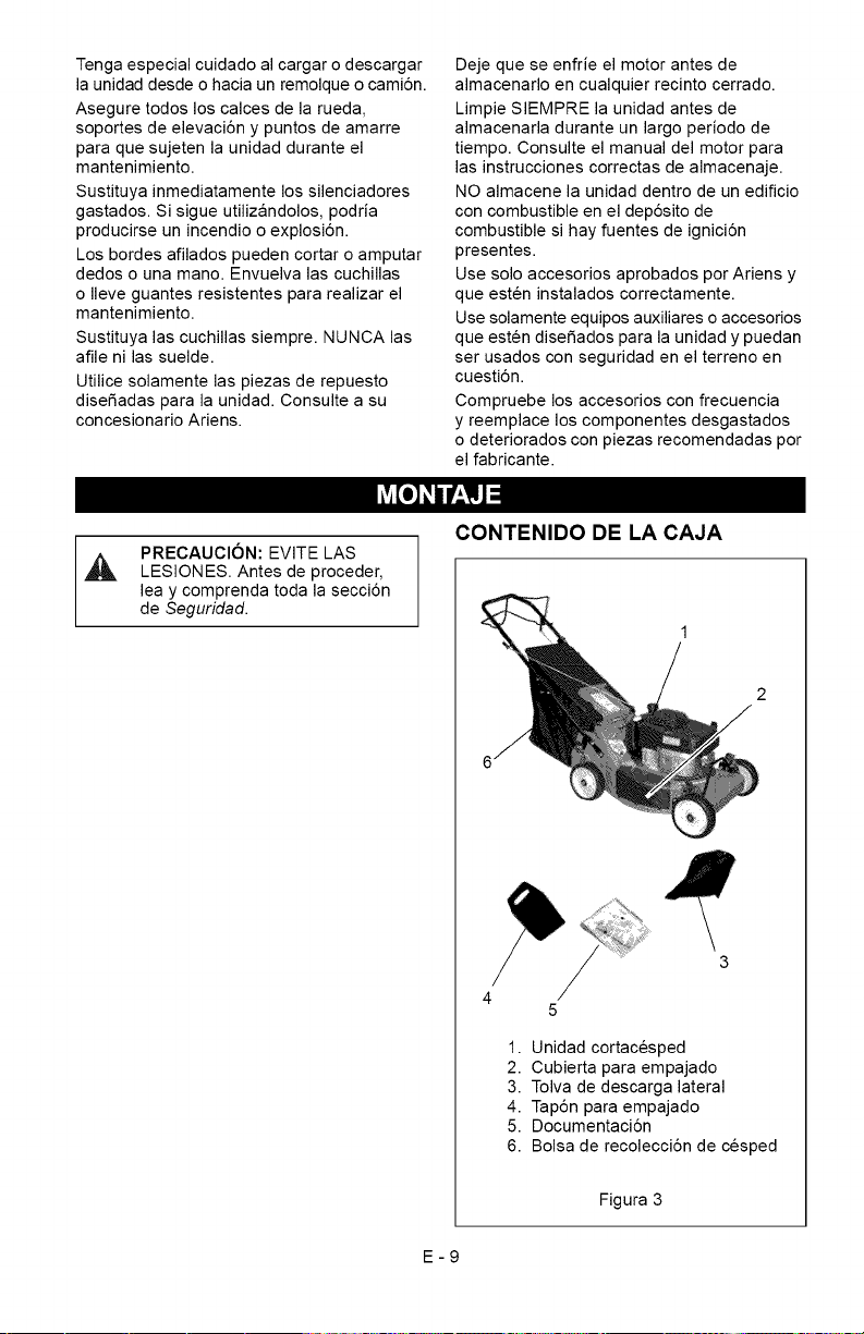
Tengaespecialcuidadoalcargarodescargar
launidaddesdeohaciaunremolqueocami6n.
Aseguretodosloscalcesdelarueda,
soportesdeelevaci6nypuntosdeamarre
paraquesujetenlaunidadduranteel
mantenimiento.
Sustituyainmediatamentelossilenciadores
gastados.Sisigueutilizandolos,podria
producirseunincendiooexplosi6n.
Losbordesafiladospuedencortaroamputar
dedosounamano.Envuelvalascuchillas
oIleveguantesresistentespararealizarel
mantenimiento.
Sustituyalascuchillassiempre.NUNCAlas
afilenilassuelde.
Utilicesolamentelaspiezasderepuesto
disefiadasparalaunidad.Consulteasu
concesionarioAriens.
Dejequeseenfrieelmotorantesde
almacenarloencualquierrecintocerrado.
LimpieSIEMPRElaunidadantesde
almacenarladuranteunlargoperiodode
tiempo.Consulteelmanualdelmotorpara
lasinstruccionescorrectasdealmacenaje.
NOalmacenelaunidaddentrodeunedificio
concombustibleeneldep6sitode
combustiblesihayfuentesdeignici6n
presentes.
UsesoloaccesoriosaprobadosporAriensy
queesteninstaladoscorrectamente.
Usesolamenteequiposauxiliaresoaccesorios
queestendisefiadosparalaunidadypuedan
serusadosconseguridadenelterrenoen
cuesti6n.
Compruebelosaccesoriosconfrecuencia
yreemplaceloscomponentesdesgastados
odeterioradosconpiezasrecomendadaspor
elfabricante.
PRECAUClON:EVITELAS
LESIONES.Antesdeproceder,
leaycomprendatodalasecci6n
deSeguridad.
CONTENIDO DE LA CAJA
1. Unidad cortacesped
2. Cubierta para empajado
3. Tolva de descarga lateral
4. Tap6n para empajado
5. Documentaci6n
6. Bolsa de recolecci6n de cesped
Figura 3
E-9
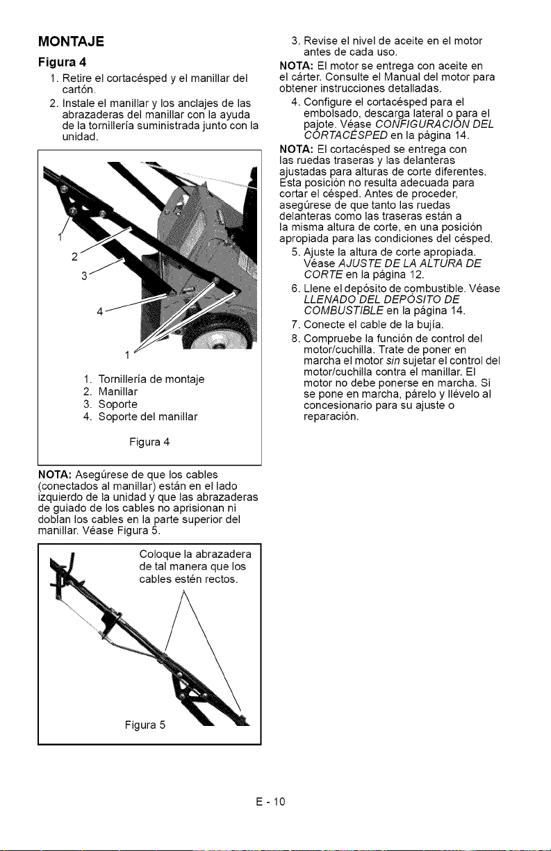
MONTAJE
Figura 4
1. Retire el cortacesped y el manillar del
cart6n.
2. Instale el manillar y los anclajes de las
abrazaderas del manillar con la ayuda
de la tornilleria suministrada junto con la
unidad.
1. Tornilleria de montaje
2. Manillar
3. Soporte
4. Soporte del manillar
Figura 4
NOTA: AsegQrese de que los cables
(conectados al manillar) estan en el lado
izquierdo de la unidad y que las abrazaderas
de guiado de los cables no aprisionan ni
doblan los cables en la parte superior del
manillar. Vease Figura 5.
Coloque la abrazadera
de tal manera que los
cables esten rectos.
3. Revise el nivel de aceite en el motor
antes de cada uso.
NOTA: El motor se entrega con aceite en
el carter. Consulte el Manual del motor para
obtener instrucciones detalladas.
4. Configure el cortacesped para el
embolsado, descarga lateral o para el
pajote. Vease CONFIGURA CION DEL
CORTACESPED en la pagina 14.
NOTA: El cortacesped se entrega con
las ruedas traseras y las delanteras
ajustadas para alturas de corte diferentes.
Esta posici6n no resulta adecuada para
cortar el cesped. Antes de proceder,
asegerese de que tanto las ruedas
delanteras como las traseras estan a
la misma altura de corte, en una posici6n
apropiada para las condiciones del cesped.
5. Ajuste la altura de corte apropiada.
Vease AJUSTE DE LA ALTURA DE
CORTE en la pagina 12.
6. Llene el dep6sito de combustible. Vease
LLENADO DEL DEPOSITO DE
COMBUSTIBLE en la pagina 14.
7. Conecte el cable de la bujia.
8. Compruebe la funci6n de control del
motor/cuchilla. Trate de poner en
marcha el motor sin sujetar el control del
motor/cuchilla contra el manillar. El
motor no debe ponerse en marcha. Si
se pone en marcha, parelo y Ilevelo al
concesionario para su ajuste o
reparaci6n.
\
Figura 5
E-10
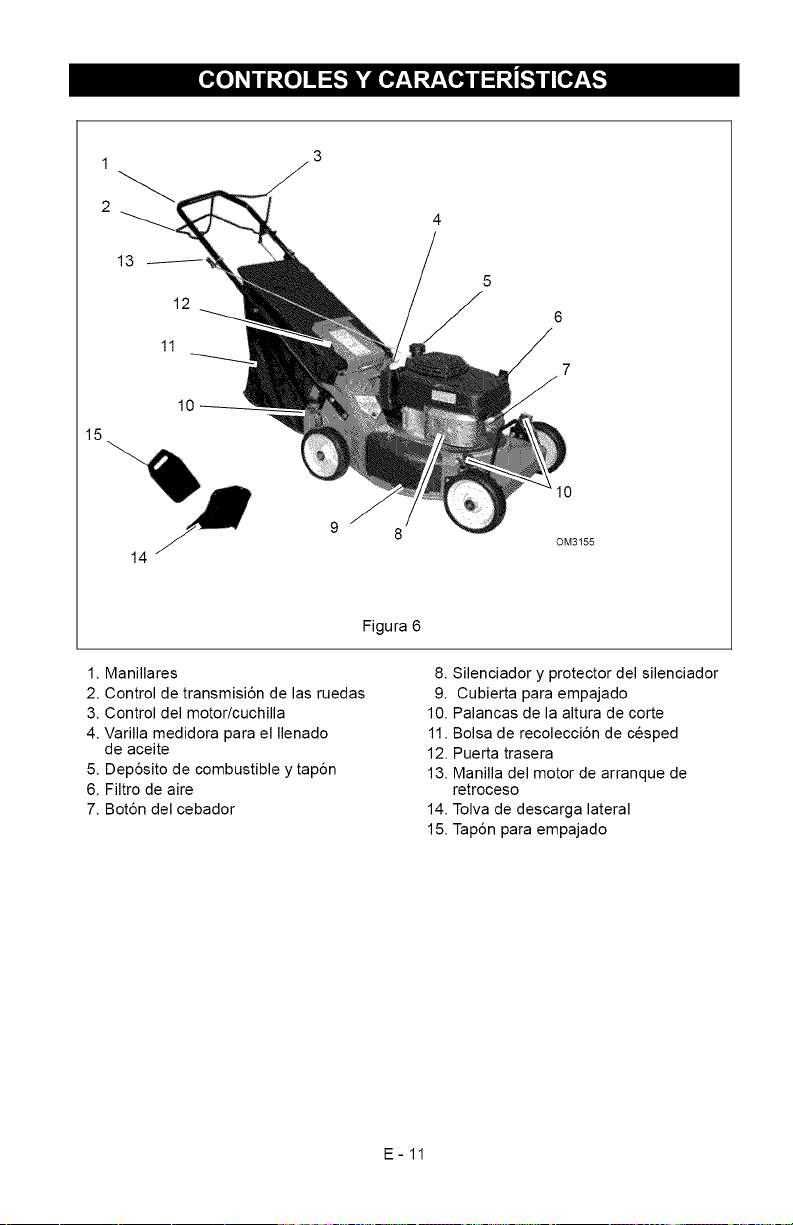
1
2
15
13
12
10
6
7
14
0M3155
Figura 6
1. Manillares
2. Control de transmisi6n de las ruedas
3. Control del motor/cuchilla
4. Varilla medidora para el Ilenado
de aceite
5. Dep6sito de combustible y tap6n
6. Filtro de aire
7. Bot6n del cebador
8. Silenciador y protector del silenciador
9. Cubierta para empajado
10. Palancas de la altura de corte
11. Bolsa de recolecci6n de cesped
12. Puerta trasera
13. Manilla del motor de arranque de
retroceso
14. Tolva de descarga lateral
15. Tap6n para empajado
E-11
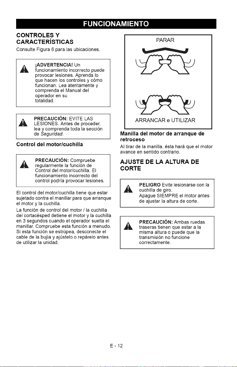
_o] _r:1_V_l1:1_/ [o]
CONTROLES Y
CARACTERiSTICAS
Consulte Figura 6 para las ubicaciones.
iADVERTENCIA7 Un
funcionamiento incorrecto puede
provocar lesiones. Aprenda Io
que hacen los controles y c6mo
funcionan. Lea atentamente y
comprenda el Manual del
operador en su
totalidad.
PRECAUCION: EVITE LAS
_L, LESIONES. Antes de proceder,
lea y comprenda toda la secci6n
de Seguridad.
Control del motor/cuchilla
A
PRECAUCION: Compruebe
regularmente la funci6n de
Control del motor/cuchilla. El
funcionamiento incorrecto del
control podria provocar lesiones.
El control del motor/cuchilla tiene que estar
sujetado contra el manillar para que arranque
el motor y la cuchilla.
La funci6n de control del motor / la cuchilla
del cortacesped detiene el motor y la cuchilla
en 3 segundos cuando el operador suelta el
manillar. Compruebe esta funci6n a menudo.
Siesta funci6n se estropea, desconecte el
cable de la bujia y ajQstelo o reparelo antes
de utilizar la unidad.
PARAR
ARRANCAR e UTILIZAR
Manilla del motor de arranque de
retroceso
AI tirar de la manilla, esta hara que el motor
avance en sentido contrario.
AJUSTE DE LA ALTURA DE
CORTE
PELIGRO Evite lesionarse con la
cuchilla de giro.
Apague SIEMPRE el motor antes
de ajustar la altura de corte.
PRECAUCION: Ambas ruedas
_, traseras tienen que estar a la
misma altura o puede que la
transmisi6n no funcione
correctamente.
E-12
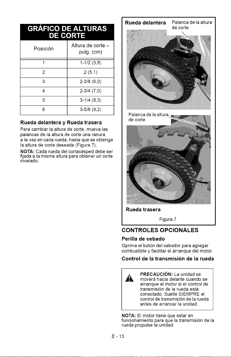
Ira]:1logo]_31/=
Posici6n
1
2
3
4
5
6
Altura de corte -
pulg. (cm)
1-1!2 (3,8)
2 (5,1)
2-3!8 (6,0)
2-3/4 (7,0)
3-1/4 (8,3)
3-5!8 (9,2)
Rueda delantera y Rueda trasera
Para cambiar la altura de corte, mueva las
palancas de la altura de corte una ranura
a la vez en cada rueda, hasta que se obtenga
la altura de corte deseada (Figura 7).
NOTA: Cada rueda del cortacesped debe ser
fijada a la misma altura para obtener un corte
nivelado.
Rueda delantera Palanca de la altura
de corte
Palanca de la altura
de corte
Rueda trasera
Figura 7
CONTROLES OPCIONALES
Perilla de cebado
Oprima el bot6n del cebador para agregar
combustible y facilitar el arranque del motor.
Control de la transmision de la rueda
PRECAUCION: La unidad se
movera hacia delante cuando se
arranque el motor si el control de
transmisi6n de la rueda esta
conectado. Suelte SIEMPRE el
control de transmisi6n de la rueda
antes de arrancar la unidad.
NOTA: El motor tiene que estar en
funcionamiento para que la transmisi6n de la
rueda propulse la unidad.
E-13
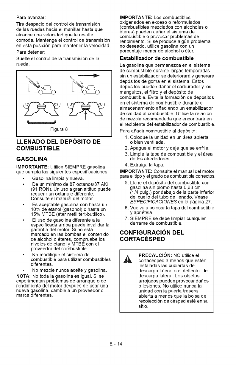
Paraavanzar:
Tiredespaciodelcontroldetransmisi6n
delasruedashaciaelmanillarhastaque
alcanceunavelocidadqueleresulte
c6moda.Mantengaelcontroldetransmisi6n
enestaposici6nparamantenerlavelocidad.
Paradetener:
Suelteelcontroldelatransmisi6ndela
rueda.
Figura8
LLENADO DEL DEPOSITO DE
COMBUSTIBLE
GASOLINA
IMPORTANTE: Utilice SIEMPRE gasolina
que cumpla las siguientes especificaciones:
Gasolina limpia y nueva.
De un minimo de 87 octanos/87 AKI
(91 RON). Un uso a gran altitud puede
requerir un octanaje diferente.
Consulte el manual del motor.
Es aceptable gasolina con hasta un
10% de etanol (gasohol) o hasta un
15% MTBE (eter metil tert-butilico).
El uso de gasolina diferente a la
especificada arriba puede invalidar la
garantia del motor. Si no esta
marcado en las bombas el contenido
de alcohol o eteres, compruebe los
niveles de etanol y MTBE con el
proveedor del combustible.
No modifique el sistema de
combustible para utilizar combustibles
diferentes.
No mezcle nunca aceite y gasolina.
NOTA: No toda la gasolina es igual. Si se
experimentan problemas de arranque o de
rendimiento del motor despues de usar una
nueva gasolina, cambie a un proveedor o
marca diferentes.
IMPORTANTE: Los combustibles
oxigenados en exceso o reformulados
(combustibles mezclados con alcoholes o
eteres) pueden daSar el sistema de
combustible o provocar problemas de
rendimiento. Si se produce algen problema
no deseado, utilice gasolina con un
porcentaje menor de alcohol o eter.
Estabilizador de combustible
La gasolina que permanezca en el sistema
de combustible durante largas temporadas
sin un estabilizador se deteriorara y generara
dep6sitos de goma en el sistema. Estos
dep6sitos pueden daSar el carburador y los
manguitos, el filtro y el dep6sito de
combustible. Evite la formaci6n de dep6sitos
en el sistema de combustible durante el
almacenamiento aSadiendo un estabilizador
de calidad al combustible. Utilice la relaci6n
de mezcla recomendada que encontrara en
el recipiente del estabilizador de combustible.
Para aSadir combustible al dep6sito:
1. Coloque la unidad en un area abierta
o bien ventilada.
2. Apague el motor y deje que se enfrie.
3. Limpie la tapa de combustible y el area
de los alrededores.
4. Extraiga la tapa.
IMPORTANTE: Consulte el manual del motor
para el tipo y el grado de combustible correctos.
5. Llene el dep6sito del combustible con
gasolina sin plomo hasta 0,63 cm
(1/4 pulg.) por debajo de la parte inferior
del cuello del tubo de Ilenado. Vease
ESPECIFICACIONES en la pagina 27.
6. Vuelva a colocar la tapa del combustible
y aprietela.
7. SIEMPRE se debe limpiar cualquier
derrame de combustible.
CONFIGURACION DEL
CORTACESPED
PRECAUCION: NO utilice el
cortacesped a menos que esten
instaladas las cubiertas de
descarga lateral o el deflector de
descarga lateral. Los objetos
arrojados pueden provocar da_os
o lesiones. No utilice nunca la
unidad con la puerta trasera
abierta a menos que la bolsa de
recolecci6n de cesped este en su
sitio.
E-14
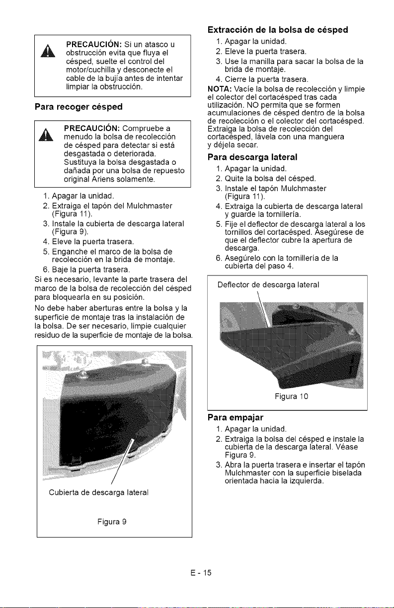
PRECAUClON:Siunatascou
obstrucci6nevitaquefluyael
cesped,suelteelcontroldel
motor/cuchillaydesconecteel
cabledelabujiaantesdeintentar
limpiarlaobstrucci6n.
Para recoger cesped
PRECAUClON: Compruebe a
menudo la bolsa de recolecci6n
de cesped para detectar si esta
desgastada o deteriorada.
Sustituya la bolsa desgastada o
dafiada por una bolsa de repuesto
original Ariens solamente.
1. Apagar la unidad.
2. Extraiga el tap6n del Mulchmaster
(Figura 11).
3. Instale la cubierta de descarga lateral
(Figura 9).
4. Eleve la puerta trasera.
5. Enganche el marco de la bolsa de
recolecci6n en la brida de montaje.
6. Baje la puerta trasera.
Si es necesario, levante la parte trasera del
marco de la bolsa de recolecci6n del cesped
para bloquearla en su posici6n.
No debe haber aberturas entre la bolsa y la
superficie de montaje tras la instalaci6n de
la bolsa. De ser necesario, limpie cualquier
residuo de la superficie de montaje de la bolsa.
Cubierta de descarga lateral
Figura 9
Extraccion de la bolsa de cesped
1. Apagar la unidad.
2. Eleve la puerta trasera.
3. Use la manilla para sacar la bolsa de la
brida de montaje.
4. Cierre la puerta trasera.
NOTA: Vacie la bolsa de recolecci6n y limpie
el colector del cortacesped tras cada
utilizaci6n. NO permita que se formen
acumulaciones de cesped dentro de la bolsa
de recolecci6n o el colector del cortacesped.
Extraiga la bolsa de recolecci6n del
cortacesped, lavela con una manguera
y dejela secar.
Para descarga lateral
1. Apagar la unidad.
2. Quite la bolsa del cesped.
3. Instale el tap6n Mulchmaster
(Figura 11).
4. Extraiga la cubierta de descarga lateral
y guarde la tomilleria.
5. Fije el deflector de descarga lateral a los
tomillos del cortacesped. Asegerese de
que el deflector cubre la apertura de
descarga.
6. AsegQrelo con la tomilleria de la
cubierta del paso 4.
Deflector de descarga lateral
Figura 10
Para empajar
1. Apagar la unidad.
2. Extraiga la bolsa del cesped e instale la
cubierta de la descarga lateral. Vease
Figura 9.
3. Abra la puerta trasera e insertar el tap6n
Mulchmaster con la superficie biselada
orientada hacia la izquierda.
E-15
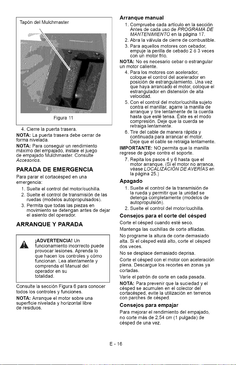
Tap6ndelMulchmaster
Figura11
4.Cierrelapuertatrasera.
NOTA:Lapuertatraseradebecerrarde
formanivelada.
NOTA:Paraconseguirunrendimiento
maximodelempajado,instaleeljuego
deempajadoMulchmaster.Consulte
Accesorios.
PARADA DE EMERGENCIA
Para parar el cortacesped en una
emergencia:
1. Suelte el control del motor/cuchilla.
2. Suelte el control de transmisi6n de las
ruedas (modelos autopropulsados).
3. Permita que todas las piezas en
movimiento se detengan antes de dejar
el asiento del operador.
ARRANQUEYPARADA
A
iADVERTENCIA7 Un
funcionamiento incorrecto puede
provocar lesiones. Aprenda Io
que hacen los controles y c6mo
funcionan. Lea atentamente y
comprenda el Manual del
operador en su
totalidad.
Consulte la secci6n Figura 6 para conocer
todos los controles y funciones.
NOTA: Arranque el motor sobre una
superficie nivelada y horizontal libre
de residuos.
Arranque manual
1. Compruebe cada articulo en la secci6n
Antes de cada uso de PROGRAMA DE
MANTENIMIENTO en la pagina 17.
2. Abra la valvula de cierre de combustible.
3. Para aquellos motores con cebador,
empuje la perilla de cebado 2 6 3 veces
con un motor frio.
NOTA: No es necesario cebar o estrangular
un motor caliente.
4. Para los motores con acelerador,
coloque el control del acelerador en
posici6n de estrangulamiento. Una vez
que haya arrancado el motor, coloque el
estrangulador en distensi6n de alta
velocidad.
5. Con el control del motor/cuchilla sujeto
contra el manillar, agarre la manilla de
arranque y tire lentamente de la cuerda
hasta que este tensa. Este es el modo
compresi6n. Deje que la cuerda se
retraiga lentamente.
6. Tire del cable de manera rapida y
continuada para arrancar el motor.
Deje que el cable se retraiga lentamente.
IMPORTANTE: NO permita que la manilla
regrese de golpe contra el soporte.
7. Repita los pasos 4 y 6 hasta que el
motor arranque. (Si el motor no arranca,
vease LOCALIZACION DE AVERIAS en
la pagina 25.)
Apagado
1. Suelte el control de la transmisi6n de
la rueda y permitir que la unidad se
detenga completamente (modelos de
autopropulsi6n).
2. Suelte el control del motor/cuchilla.
Consejos para el corte del cesped
Corte el cesped cuando este seco.
Mantenga las cuchillas de corte afiladas.
No programe la altura de corte demasiado
alta. Si el cesped esta alto, corte el cesped
dos veces.
No se desplace demasiado deprisa.
Corte el cesped con el motor con aceleraci6n
plena. Descargue los recortes en zonas ya
cortadas.
Varie el patr6n de corte en cada pasada.
NOTA: Para prevenir que la suciedad y el
cesped se acumulen en el colector del
cortacesped, evite la utilizaci6n en terrenos
con parches de cesped.
Consejos para empajar
Para mejorar el rendimiento del empajado,
no corte mas de 2,54 cm (1 pulgada) de
cesped de una vez.
E-16
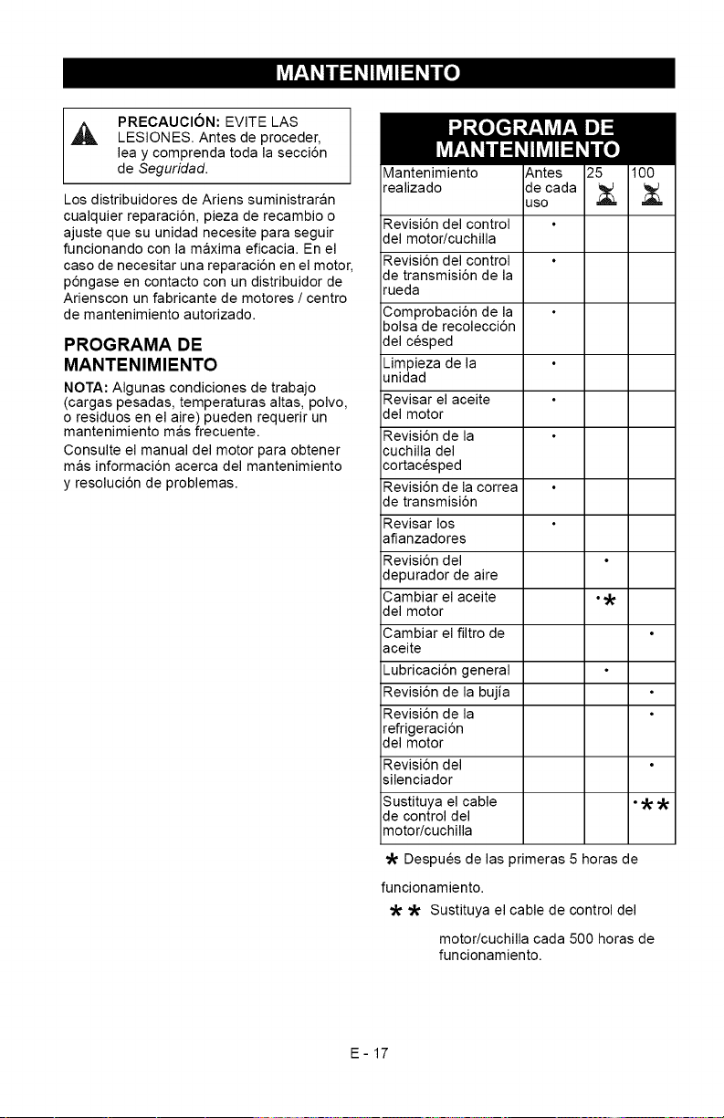
PRECAUClON:EVITELAS
,_ LESIONES. Antes de proceder,
lea y comprenda toda la secci6n
de Seguridad.
Los distribuidores de Ariens suministraran
cualquier reparaci6n, pieza de recambio o
ajuste que su unidad necesite para seguir
funcionando con la maxima eficacia. En el
caso de necesitar una reparaci6n en el motor,
p6ngase en contacto con un distribuidor de
Arienscon un fabricante de motores / centro
de mantenimiento autorizado.
PROGRAMA DE
MANTENIMIENTO
NOTA: Algunas condiciones de trabajo
(cargas pesadas, temperaturas altas, polvo,
o residuos en el aire) pueden requerir un
mantenimiento mas frecuente.
Consulte el manual del motor para obtener
mas informaci6n acerca del mantenimiento
y resoluci6n de problemas.
Mantenimiento
realizado
Revisi6n del control
del motor/cuchilla
Revisi6n del control
de transmisi6n de la
rueda
Comprobaci6n de la
bolsa de recolecci6n
del cesped
Limpieza de la
unidad
Revisar el aceite
del motor
Revisi6n de la
cuchilla del
cortacesped
Revisi6n de la correa
de transmisi6n
Revisar los
afianzadores
Revisi6n del
depurador de aire
Cambiar el aceite °
del motor
Cambiar el filtro de
aceite
Lubricaci6n general
Revisi6n de la bujia
Revisi6n de la
refrigeraci6n
del motor
Revisi6n del
silenciador
Sustituya el cable ° _
de control del
motor/cuchilla
Despues de las primeras 5 horas de
funcionamiento.
_ Sustituya el cable de control del
motor/cuchilla cada 500 horas de
funcionamiento.
E-17
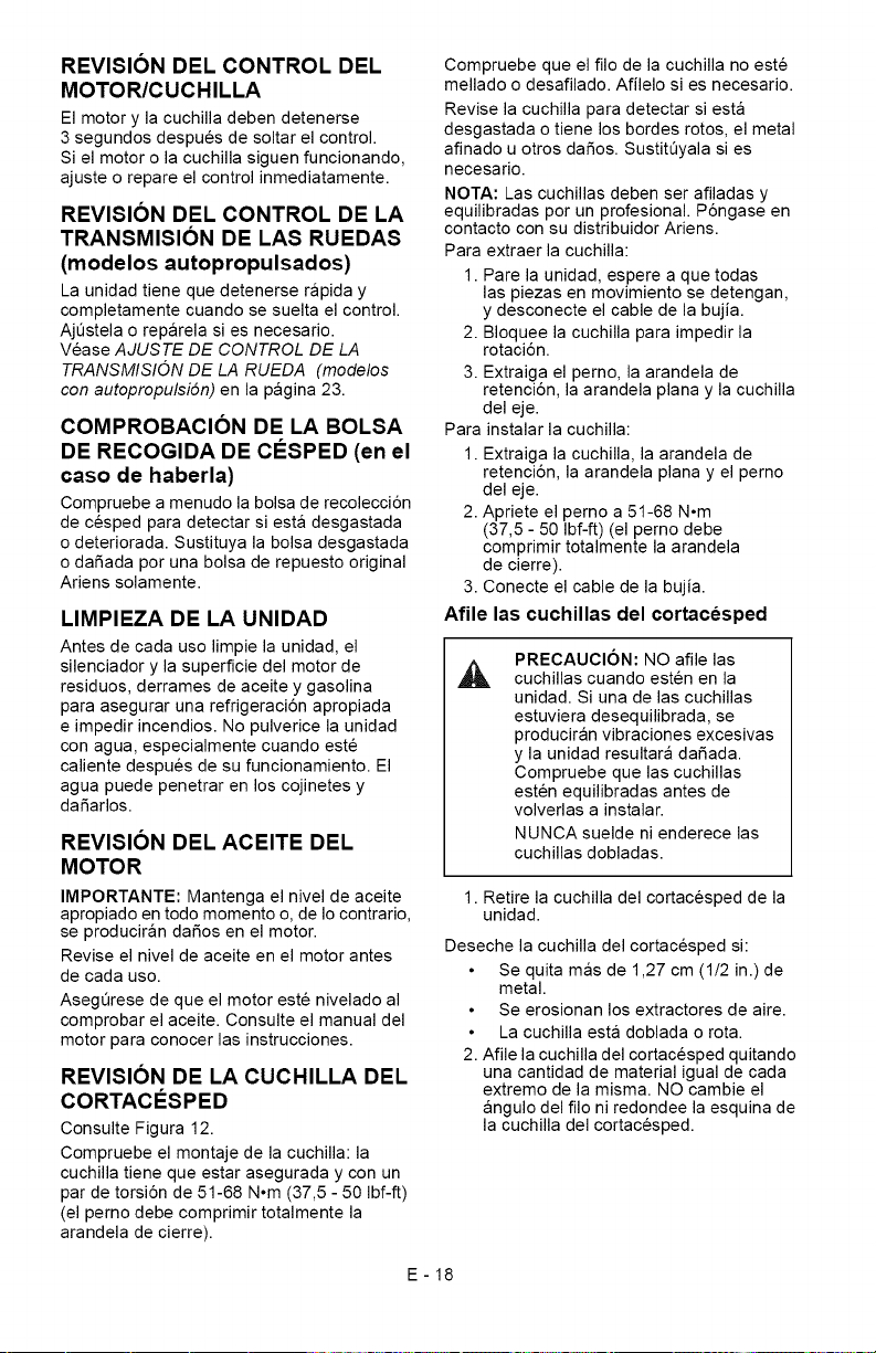
REVISION DEL CONTROL DEL
MOTOR/CUCHILLA
El motor y la cuchilla deben detenerse
3 segundos despues de soltar el control.
Si el motor o la cuchilla siguen funcionando,
ajuste o repare el control inmediatamente.
REVISION DEL CONTROL DE LA
TRANSMISION DE LAS RUEDAS
(modelos autopropulsados)
La unidad tiene que detenerse rapida y
completamente cuando se suelta el control.
AjQstela o reparela si es necesario.
Vease AJUSTE DE CONTROL DE LA
TRANSMISION DE LA RUEDA (modelos
con autopropulsi6n) en la pagina 23.
COMPROBACION DE LA BOLSA
DE RECOGIDA DE CF:SPED (en el
caso de haberla)
Compruebe a menudo la bolsa de recolecci6n
de cesped para detectar siesta desgastada
o deteriorada. Sustituya la bolsa desgastada
o dafiada por una bolsa de repuesto original
Ariens solamente.
LIMPIEZA DE LA UNIDAD
Antes de cada uso limpie la unidad, el
silenciador y la superficie del motor de
residuos, derrames de aceite y gasolina
para asegurar una refrigeraci6n apropiada
e impedir incendios. No pulverice la unidad
con agua, especialmente cuando este
caliente despues de su funcionamiento. El
agua puede penetrar en los cojinetes y
dafiarlos.
REVISION DEL ACEITE DEL
MOTOR
IMPORTANTE: Mantenga el nivel de aceite
apropiado en todo momento o, de Io contrario,
se produciran dafios en el motor.
Revise el nivel de aceite en el motor antes
de cada uso.
Asegerese de que el motor este nivelado al
comprobar el aceite. Consulte el manual del
motor para conocer las instrucciones.
REVISION DE LA CUCHILLA DEL
CORTACESPED
Consulte Figura 12.
Compruebe el montaje de la cuchilla: la
cuchilla tiene que estar asegurada y con un
par de torsi6n de 51-68 N°m (37,5 - 50 Ibf-ft)
(el perno debe comprimir totalmente la
arandela de cierre).
Compruebe que el filo de la cuchilla no este
mellado o desafilado. Afilelo si es necesario.
Revise la cuchilla para detectar siesta
desgastada o tiene los bordes rotos, el metal
afinado u otros dafios. SustitQyala si es
necesario.
NOTA: Las cuchillas deben ser afiladas y
equilibradas por un profesional. P6ngase en
contacto con su distribuidor Ariens.
Para extraer la cuchilla:
1. Pare la unidad, espere a que todas
las piezas en movimiento se detengan,
y desconecte el cable de la bujia.
2. Bloquee la cuchilla para impedir la
rotaci6n.
3. Extraiga el perno, la arandela de
retenci6n, la arandela plana y la cuchilla
del eje.
Para instalar la cuchilla:
1. Extraiga la cuchilla, la arandela de
retenci6n, la arandela plana y el perno
del eje.
2. Apriete el perno a 51-68 N°m
(37,5 - 50 Ibf-ft) (el perno debe
comprimir totalmente la arandela
de cierre).
3. Conecte el cable de la bujia.
Afile las cuchillas del cortacesped
,A
PRECAUCION: NO afile las
cuchillas cuando esten en la
unidad. Si una de las cuchillas
estuviera desequilibrada, se
produciran vibraciones excesivas
y la unidad resultara dafiada.
Compruebe que las cuchillas
esten equilibradas antes de
volverlas a instalar.
NUNCA suelde ni enderece las
cuchillas dobladas.
1. Retire la cuchilla del cortacesped de la
unidad.
Deseche la cuchilla del cortacesped si:
Se quita mas de 1,27 cm (1/2 in.) de
metal.
Se erosionan los extractores de aire.
La cuchilla esta doblada o rota.
2. Afile la cuchilla del cortacesped quitando
una cantidad de material igual de cada
extremo de la misma. NO cambie el
angulo del filo ni redondee la esquina de
la cuchilla del cortacesped.
E-18
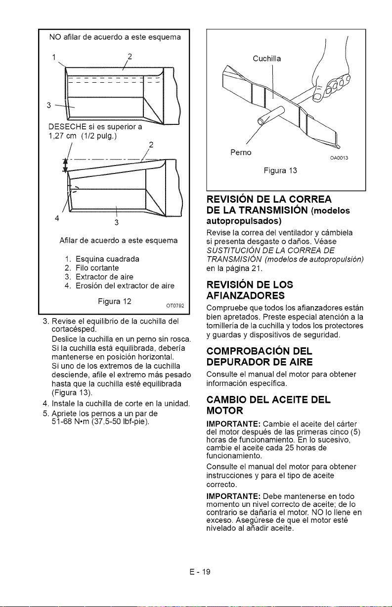
NOafilardeacuerdoaesteesquema
1 2
\ /
DESECHE si es superior a
1,27 cm (1/2 pulg.)
4 _
3
Afilar de acuerdo a este esquema
1. Esquina cuadrada
2. Filo cortante
3. Extractor de aire
4. Erosi6n del extractor de aire
Figura 12
OT0792
3. Revise el equilibrio de la cuchilla del
cortacesped.
Deslice la cuchilla en un perno sin rosca.
Si la cuchilla esta equilibrada, deberia
mantenerse en posici6n horizontal.
Si uno de los extremos de la cuchilla
desciende, afile el extremo mas pesado
hasta que la cuchilla este equilibrada
(Figura 13).
4. Instale la cuchilla de corte en la unidad.
5. Apriete los pernos a un par de
51-68 N°m (37,5-50 Ibf-pie).
Cuchilla
Perno
Figura 13
OA0013
REVISION DE LA CORREA
DE LA TRANSMISION (modelos
autopropulsados)
Revise la correa del ventilador y cambiela
si presenta desgaste o daSos. Vease
SUSTITUClON DE LA CORREA DE
TRANSMISlON (modelos de autopropulsi6n)
en la pagina 21.
REVISION DE LOS
AFIANZADORES
Compruebe que todos los afianzadores estan
bien apretados. Preste especial atenci6n a la
tornilleria de la cuchilla y todos los protectores
y guardas y dispositivos de seguridad.
COMPROBACION DEL
DEPURADOR DE AIRE
Consulte el manual del motor para obtener
informaci6n especifica.
CAMBIO DEL ACEITE DEL
MOTOR
IMPORTANTE: Cambie el aceite del carter
del motor despues de las primeras cinco (5)
horas de funcionamiento. En Io sucesivo,
cambie el aceite cada 25 horas de
funcionamiento.
Consulte el manual del motor para obtener
instrucciones y para el tipo de aceite
correcto.
IMPORTANTE: Debe mantenerse en todo
momento un nivel correcto de aceite; de Io
contrario se dafiaria el motor. NO Io Ilene en
exceso. AsegOrese de que el motor este
nivelado al afiadir aceite.
E-19
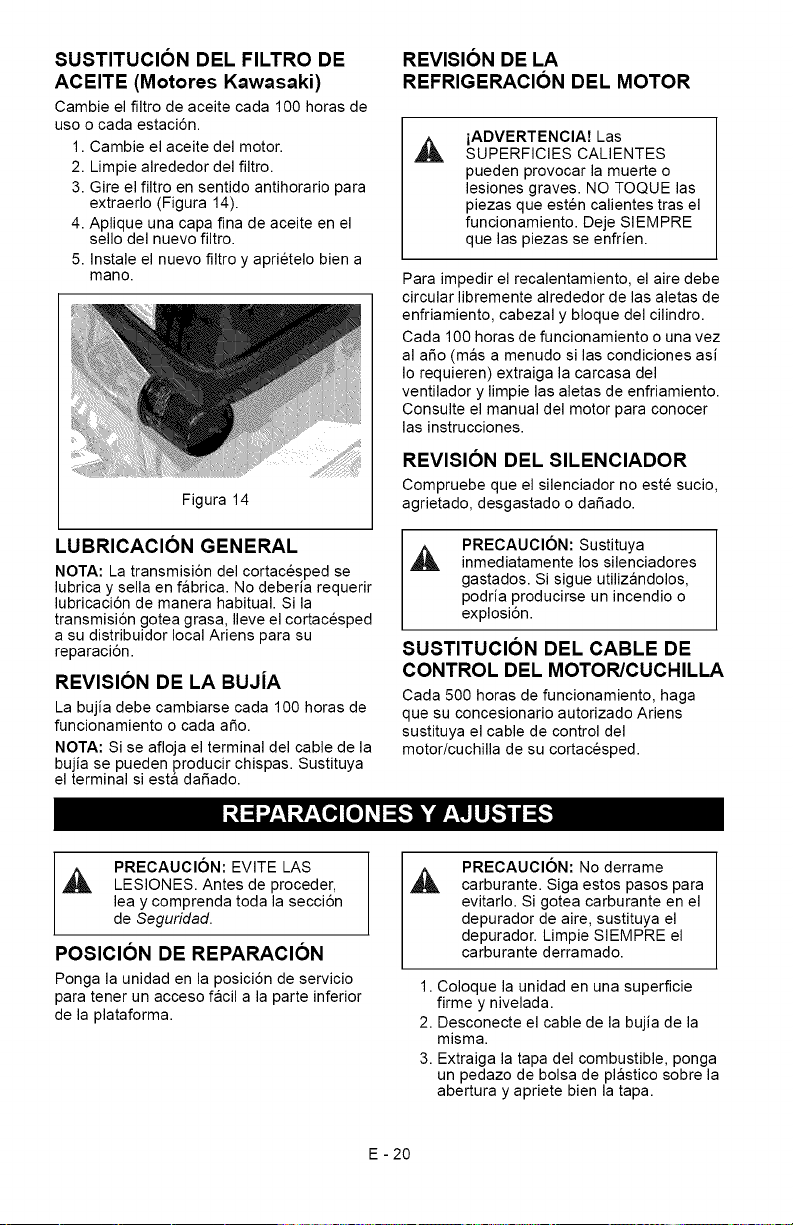
SUSTITUCION DEL FILTRO DE
ACEITE (Motores Kawasaki)
Cambie el filtro de aceite cada 100 horas de
uso o cada estaci6n.
1. Cambie el aceite del motor.
2. Limpie alrededor del filtro.
3. Gire el filtro en sentido antihorario para
extraerlo (Figura 14).
4. Aplique una capa fina de aceite en el
sello del nuevo filtro.
5. Instale el nuevo filtro y aprietelo bien a
mano.
Figura 14
LUBRICACION GENERAL
NOTA: La transmisiSn del cortacesped se
lubrica y sella en fabrica. No deberia requerir
lubricaciSn de manera habitual. Si la
transmisi6n gotea grasa, Ileve el cortacesped
a su distribuidor local Ariens para su
reparaciSn.
REVISION DE LA BUJ[A
La bujia debe cambiarse cada 100 horas de
funcionamiento o cada afio.
NOTA: Si se afloja el terminal del cable de la
bujia se pueden producir chispas. Sustituya
el terminal siesta dafiado.
REVISION DE LA
REFRIGERACION DEL MOTOR
iADVERTENCIA7 Las
SUPERFICIES CALIENTES
pueden provocar la muerte o
lesiones graves. NO TOQUE las
piezas que esten calientes tras el
funcionamiento. Deje SIEMPRE
que las piezas se enfrien.
Para impedir el recalentamiento, el aire debe
circular libremente alrededor de las aletas de
enfriamiento, cabezal y bloque del cilindro.
Cada 100 horas de funcionamiento o una vez
al afio (mas a menudo si las condiciones asi
Io requieren) extraiga la carcasa del
ventilador y limpie las aletas de enfriamiento.
Consulte el manual del motor para conocer
las instrucciones.
REVISION DEL SILENCIADOR
Compruebe que el silenciador no este sucio,
agrietado, desgastado o dafiado.
PRECAUClON: Sustituya
inmediatamente los silenciadores
gastados. Si sigue utilizandolos,
podria producirse un incendio o
explosi6n.
SUSTITUCION DEL CABLE DE
CONTROL DEL MOTOR/CUCHILLA
Cada 500 horas de funcionamiento, haga
que su concesionario autorizado Ariens
sustituya el cable de control del
motor/cuchilla de su cortacesped.
PRECAUCION: EVITE LAS
,_ LESIONES. Antes de proceder,
lea y comprenda toda la secci6n
de Seguridad.
POSICION DE REPARACION
Ponga la unidad en la posici6n de servicio
para tener un acceso facil a la parte inferior
de la plataforma.
PRECAUClON: No derrame
carburante. Siga estos pasos para
evitarlo. Si gotea carburante en el
depurador de aire, sustituya el
depurador. Limpie SIEMPRE el
carburante derramado.
1. Coloque la unidad en una superficie
firme y nivelada.
2. Desconecte el cable de la bujia de la
misma.
3. Extraiga la tapa del combustible, ponga
un pedazo de bolsa de plastico sobre la
abertura y apriete bien la tapa.
E - 20
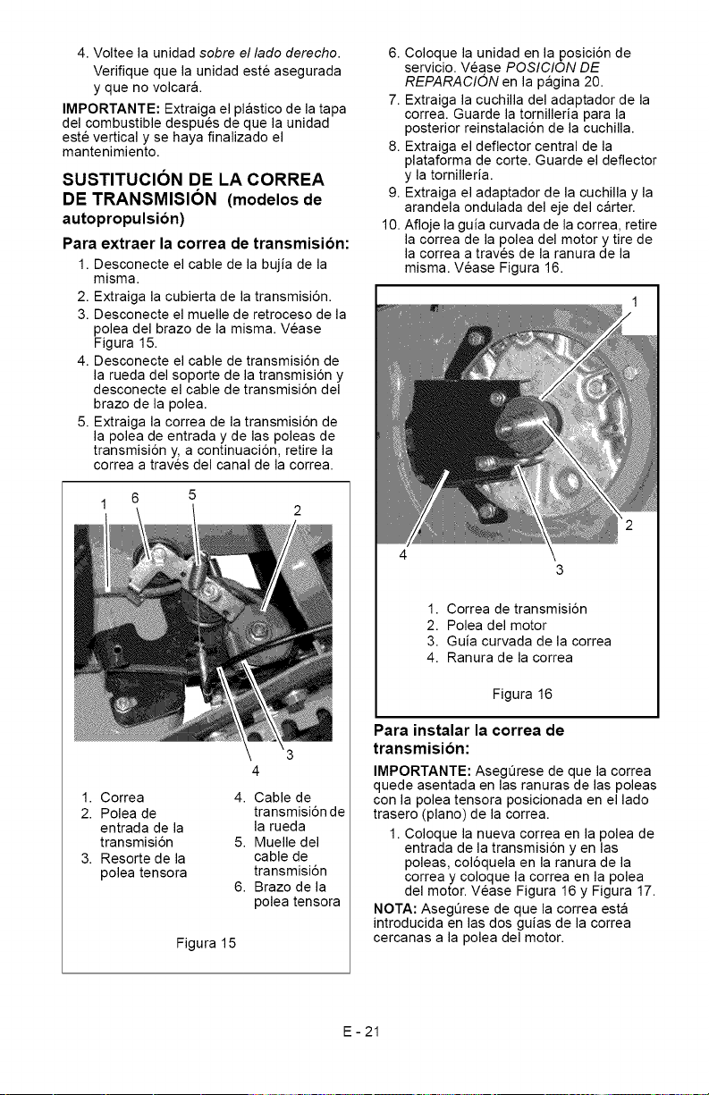
4.Volteelaunidadsobre el lado derecho.
Verifique que la unidad este asegurada
y que no volcar&
IMPORTANTE: Extraiga el plastico de la tapa
del combustible despues de que la unidad
este vertical y se haya finalizado el
mantenimiento.
SUSTITUCION DE LA CORREA
DE TRANSMISION (modelos de
autopropulsion)
Para extraer la correa de transmision:
1. Desconecte el cable de la bujia de la
misma.
2. Extraiga la cubierta de la transmisi6n.
3. Desconecte el muelle de retroceso de la
polea del brazo de la misma. Vease
Figura 15.
4. Desconecte el cable de transmisi6n de
la rueda del soporte de la transmisi6n y
desconecte el cable de transmisi6n del
brazo de la polea.
5. Extraiga la correa de la transmisi6n de
la polea de entrada y de las poleas de
transmisi6n y, a continuaci6n, retire la
correa a traves del canal de la correa.
1 6
1. Correa 4. Cable de
2. Polea de transmisi6nde
entrada de la la rueda
transmisi6n 5. Muelle del
3. Resorte de la cable de
polea tensora transmisi6n
6. Brazo de la
polea tensora
Figura 15
6. Coloque la unidad en la posici6n de
servicio. Vease POSICION DE
REPARACION en la pagina 20.
7. Extraiga la cuchilla del adaptador de la
correa. Guarde la tornilleria para la
posterior reinstalaci6n de la cuchilla.
8. Extraiga el deflector central de la
plataforma de corte. Guarde el deflector
y la tornilleria.
9. Extraiga el adaptador de la cuchilla y la
arandela ondulada del eje del carter.
10. Afloje la guia curvada de la correa, retire
la correa de la polea del motor y tire de
la correa a traves de la ranura de la
misma. Vease Figura 16.
1. Correa de transmisi6n
2. Polea del motor
3. Guia curvada de la correa
4. Ranura de la correa
Figura 16
Para instalar la correa de
transmision:
IMPORTANTE: Asegerese de que la correa
quede asentada en las ranuras de las poleas
con la polea tensora posicionada en el lado
trasero (piano) de la correa.
1. Coloque la nueva correa en la polea de
entrada de la transmisi6n yen las
poleas, col6quela en la ranura de la
correa y coloque la correa en la polea
del motor. Vease Figura 16 y Figura 17.
NOTA: Asegerese de que la correa esta
introducida en las dos guias de la correa
cercanas a la polea del motor.
E-21
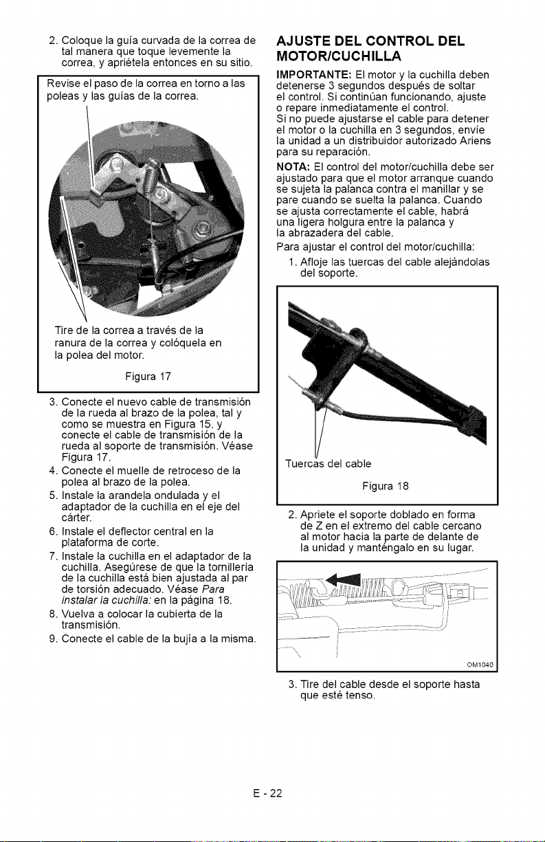
2.Coloquelaguiacurvadadelacorreade
talmaneraquetoquelevementela
correa,yaprietelaentoncesensusitio.
Reviseelpasodelacorreaentomoalas
poleasylasguiasdelacorrea.
Tiredelacorreaatravesdela
ranuradelacorreaycol6quelaen
lapoleadelmotor.
Figura17
3.Conecteelnuevocabledetransmisi6n
delaruedaalbrazodelapolea,taly
comosemuestraenFigura15,y
conecteelcabledetransmisi6ndela
ruedaalsoportedetransmisi6n.Vease
Figura17.
4.Conecteelmuellederetrocesodela
poleaalbrazodelapolea.
5.Instalelaarandelaonduladayel
adaptadordelacuchillaenelejedel
carter.
6.Instaleeldeflectorcentralenla
plataformadecorte.
7.Instalelacuchillaeneladaptadordela
cuchilla.Asegeresedequelatomilleria
delacuchillaestabienajustadaalpar
detorsi6nadecuado.VeasePara
instalarla cuchilla: en la pagina 18.
8. Vuelva a colocar la cubierta de la
transmisi6n.
9. Conecte el cable de la bujia a la misma.
AJUSTE DEL CONTROL DEL
MOTOR/CUCHILLA
IMPORTANTE: El motor y la cuchilla deben
detenerse 3 segundos despues de soltar
el control. Si continQan funcionando, ajuste
o repare inmediatamente el control.
Si no puede ajustarse el cable para detener
el motor o la cuchilla en 3 segundos, envie
la unidad a un distribuidor autorizado Ariens
para su reparaci6n.
NOTA: El control del motor/cuchilla debe ser
ajustado para que el motor arranque cuando
se sujeta la palanca contra el manillar y se
pare cuando se suelta la palanca. Cuando
se ajusta correctamente el cable, habra
una ligera holgura entre la palanca y
la abrazadera del cable.
Para ajustar el control del motor/cuchilla:
1. Afloje las tuercas del cable alejandolas
del soporte.
Tuercas del cable
Figura 18
2. Apriete el soporte doblado en forma
de Z en el extremo del cable cercano
al motor hacia la parte de delante de
la unidad y mantengalo en su lugar.
OM1040
3. Tire del cable desde el soporte hasta
que este tenso.
E - 22
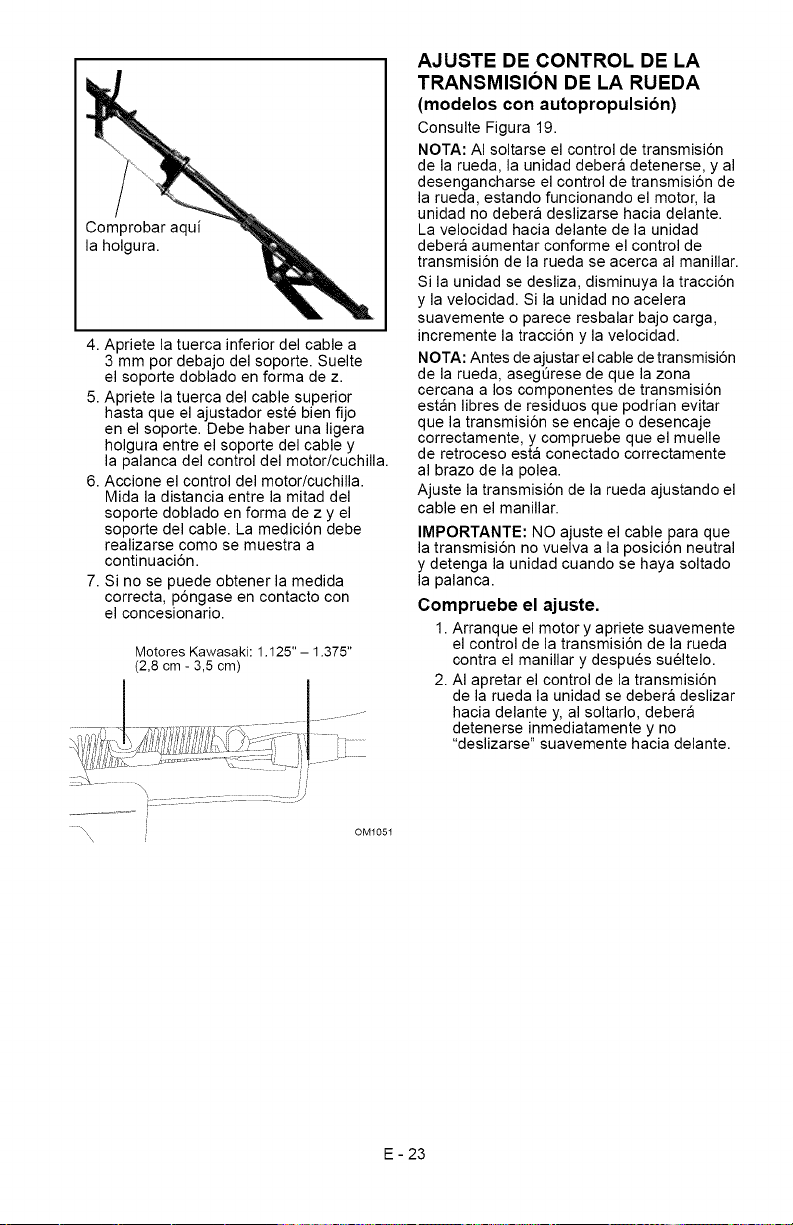
Comprobaraqui
laholgura.
4.Aprietelatuercainferiordelcablea
3mmpordebajodelsoporte.Suelte
elsoportedobladoenformadez.
5.Aprietelatuercadelcablesuperior
hastaqueelajustadorestebienfijo
enelsoporte.Debehaberunaligera
holguraentreelsoportedelcabley
lapalancadelcontroldelmotor/cuchilla.
6.Accioneelcontroldelmotor/cuchilla.
Midaladistanciaentrelamitaddel
soportedobladoenformadezyel
soportedelcable.Lamedici6ndebe
realizarsecomosemuestraa
continuaci6n.
7.Sinosepuedeobtenerlamedida
correcta,p6ngaseencontactocon
elconcesionario.
MotoresKawasaki:1.125"- 1.375"
(2,8cm-3,5cm)
OMI05I
AJUSTE DE CONTROL DE LA
TRANSMISION DE LA RUEDA
(modelos con autopropulsion)
Consulte Figura 19.
NOTA: AI soltarse el control de transmisi6n
de la rueda, la unidad debera detenerse, y al
desengancharse el control de transmisi6n de
la rueda, estando funcionando el motor, la
unidad no debera deslizarse hacia delante.
La velocidad hacia delante de la unidad
debera aumentar conforme el control de
transmisi6n de la rueda se acerca al manillar.
Si la unidad se desliza, disminuya la tracci6n
y la velocidad. Si la unidad no acelera
suavemente o parece resbalar bajo carga,
incremente la tracci6n y la velocidad.
NOTA: Antes de ajustar el cable de transmisiSn
de la rueda, asegerese de que la zona
cercana a los componentes de transmisi6n
estan libres de residuos que podrian evitar
que la transmisi6n se encaje o desencaje
correctamente, y compruebe que el muelle
de retroceso esta conectado correctamente
al brazo de la polea.
Ajuste la transmisi6n de la rueda ajustando el
cable en el manillar.
IMPORTANTE: NO ajuste el cable para que
la transmisi6n no vuelva a la posici6n neutral
y detenga la unidad cuando se haya soltado
la palanca.
Compruebe el ajuste.
1. Arranque el motor y apriete suavemente
el control de la transmisi6n de la rueda
contra el manillar y despues sueltelo.
2. AI apretar el control de la transmisi6n
de la rueda la unidad se debera deslizar
hacia delante y, al soltarlo, debera
detenerse inmediatamente y no
"deslizarse" suavemente hacia delante.
E - 23
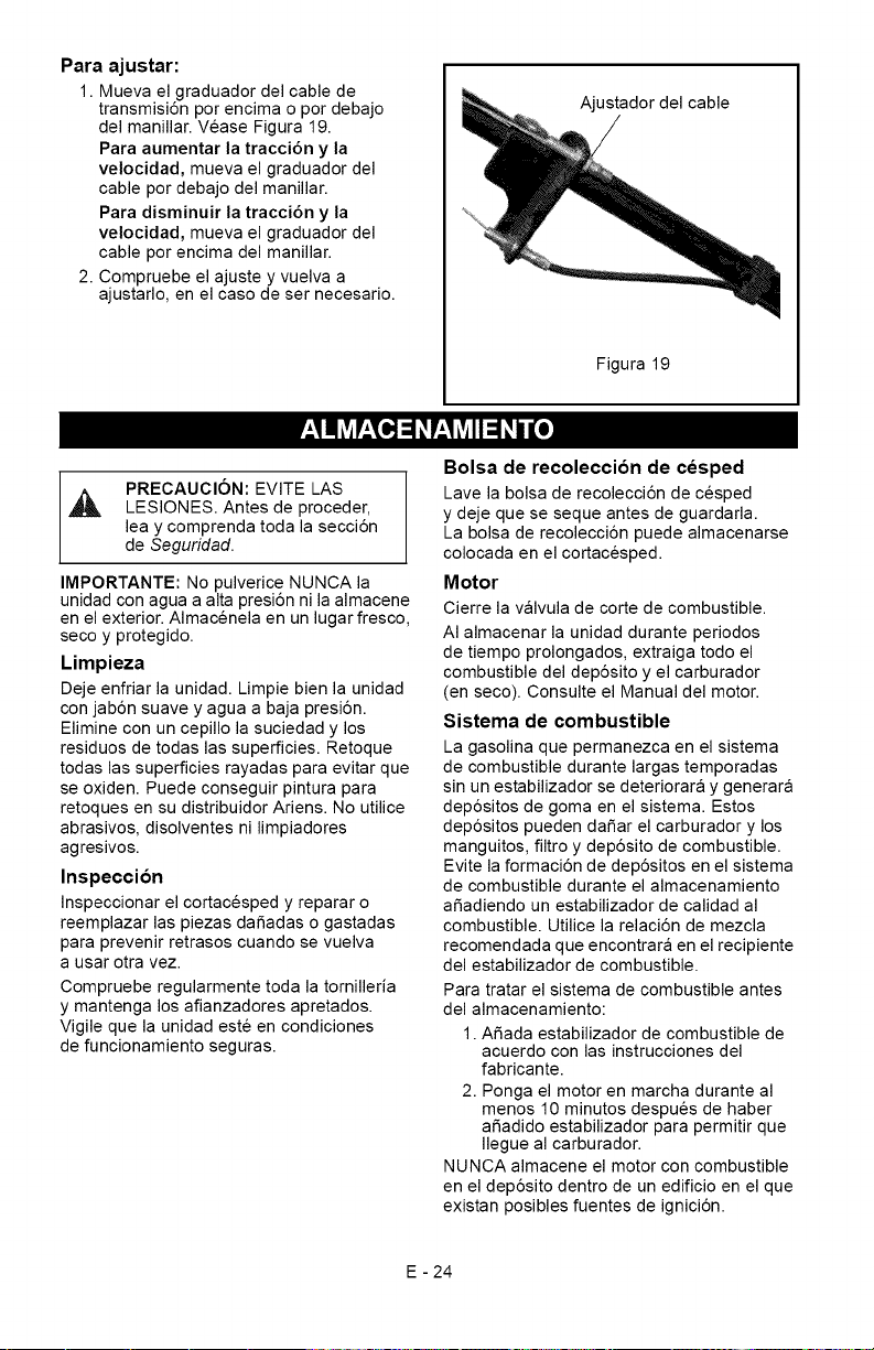
Para ajustar:
1. Mueva el graduador del cable de
transmisi6n por encima o por debajo
del manillar. Vease Figura 19.
Para aumentar la tracci6n y la
velocidad, mueva el graduador del
cable por debajo del manillar.
Para disminuir la tracci6n y la
velocidad, mueva el graduador del
cable por encima del manillar.
2. Compruebe el ajuste y vuelva a
ajustarlo, en el caso de ser necesario.
Ajustador del cable
Figura 19
PRECAUCION: EVITE LAS
LESIONES. Antes de proceder,
lea y comprenda toda la secci6n
de Seguridad.
IMPORTANTE: No pulverice NUNCA la
unidad con agua a alta presi6n ni la almacene
en el exterior. Almacenela en un lugar fresco,
seco y protegido.
Limpieza
Deje enfriar la unidad. Limpie bien la unidad
con jab6n suave y agua a baja presi6n.
Elimine con un cepillo la suciedad y los
residuos de todas las superficies. Retoque
todas las superficies rayadas para evitar que
se oxiden. Puede conseguir pintura para
retoques en su distribuidor Ariens. No utilice
abrasivos, disolventes ni limpiadores
agresivos.
Inspeccion
Inspeccionar el cortacesped y reparar o
reemplazar las piezas dafiadas o gastadas
para prevenir retrasos cuando se vuelva
a usar otra vez.
Compruebe regularmente toda la tornilleria
y mantenga los afianzadores apretados.
Vigile que la unidad este en condiciones
de funcionamiento seguras.
Bolsa de recoleccion de cesped
Lave la bolsa de recolecci6n de cesped
y deje que se seque antes de guardarla.
La bolsa de recolecci6n puede almacenarse
colocada en el cortacesped.
Motor
Cierre la valvula de corte de combustible.
AI almacenar la unidad durante periodos
de tiempo prolongados, extraiga todo el
combustible del dep6sito y el carburador
(en seco). Consulte el Manual del motor.
Sistema de combustible
La gasolina que permanezca en el sistema
de combustible durante largas temporadas
sin un estabilizador se deteriorara y generara
dep6sitos de goma en el sistema. Estos
dep6sitos pueden dafiar el carburador y los
manguitos, filtro y dep6sito de combustible.
Evite la formaci6n de dep6sitos en el sistema
de combustible durante el almacenamiento
afiadiendo un estabilizador de calidad al
combustible. Utilice la relaci6n de mezcla
recomendada que encontrara en el recipiente
del estabilizador de combustible.
Para tratar el sistema de combustible antes
del almacenamiento:
1. Afiada estabilizador de combustible de
acuerdo con las instrucciones del
fabricante.
2. Ponga el motor en marcha durante al
menos 10 minutos despues de haber
afiadido estabilizador para permitir que
Ilegue al carburador.
NUNCA almacene el motor con combustible
en el dep6sito dentro de un edificio en el que
existan posibles fuentes de ignici6n.
E - 24
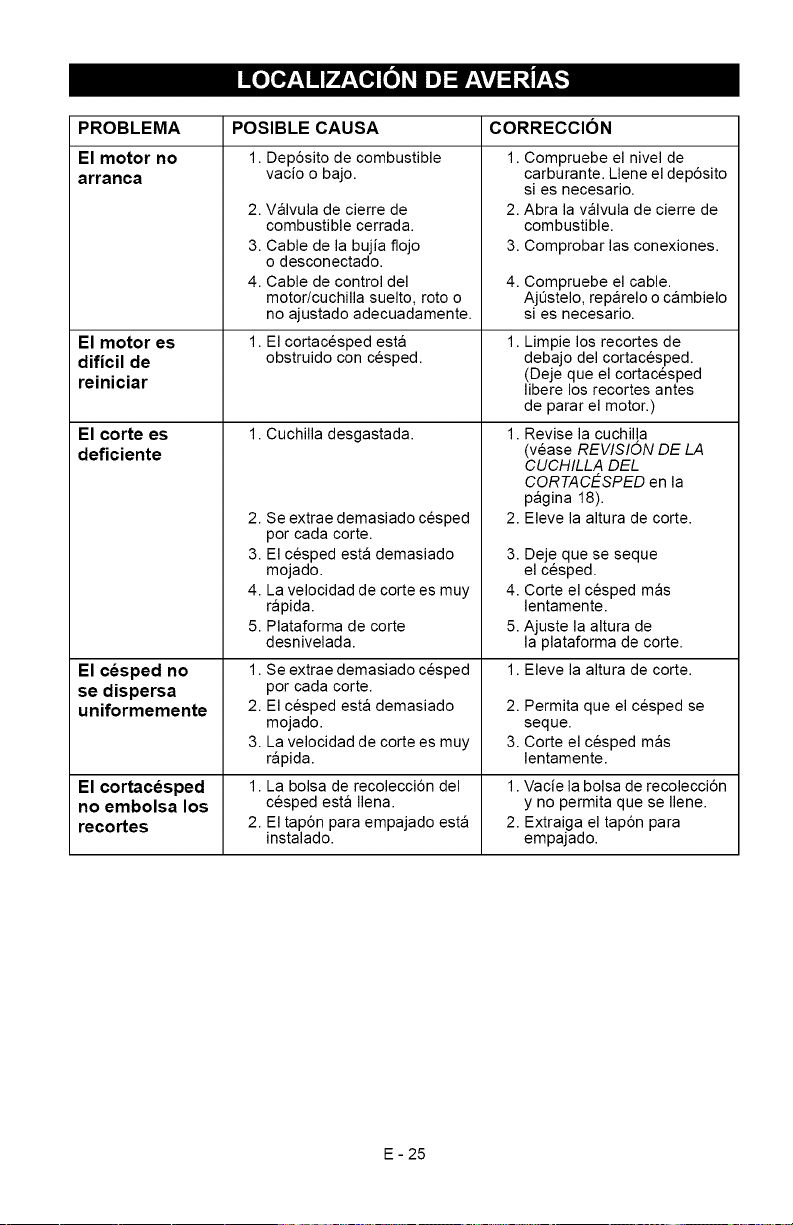
PROBLEMA
El motor no
arranca
El motor es
dificil de
reiniciar
El corte es
deficiente
El cesped no
se dispersa
uniformemente
El cortacesped
no embolsa los
recortes
POSIBLE CAUSA
1. Dep6sito de combustible
vacio o bajo.
2. Valvula de cierre de
combustible cerrada.
3. Cable de la bujia flojo
o desconectado.
4. Cable de control del
motor/cuchilla suelto, roto o
no ajustado adecuadamente.
El cortacesped esta
obstruido con cesped.
1. Cuchilla desgastada.
2. Se extrae demasiado cesped
por cada corte.
3. El cesped esta demasiado
mojado.
4. La velocidad de corte es muy
rapida.
5. Plataforma de corte
desnivelada.
1. Se extrae demasiado cesped
por cada corte.
2. El cesped esta demasiado
mojado.
3. La velocidad de corte es muy
rapida.
1. La bolsa de recolecci6n del
cesped esta Ilena.
2. El tap6n para empajado esta
instalado.
CORRECCION
1. Compruebe el nivel de
carburante. Llene el dep6sito
si es necesario.
2. Abra la valvula de cierre de
combustible.
3. Comprobar las conexiones.
4. Compruebe el cable.
AjQstelo, reparelo o cambielo
si es necesario.
Limpie los recortes de
debajo del cortacesped.
(Deje que el cortacesped
libere los recortes antes
de parar el motor.)
1. Revise la cuchilla
(vease REWSION DE LA
CUCHILLA DEL
CORTACESPED en la
pagina 18).
2. Eleve la altura de corte.
3. Deje que se seque
el cesped.
4. Corte el cesped mas
lentamente.
5. Ajuste la altura de
la plataforma de corte.
1. Eleve la altura de corte.
2. Permita que el cesped se
seque.
3. Corte el cesped mas
lentamente.
1. Vacie la bolsa de recolecci6n
y no permita que se Ilene.
2. Extraiga el tap6n para
empajado.
E - 25
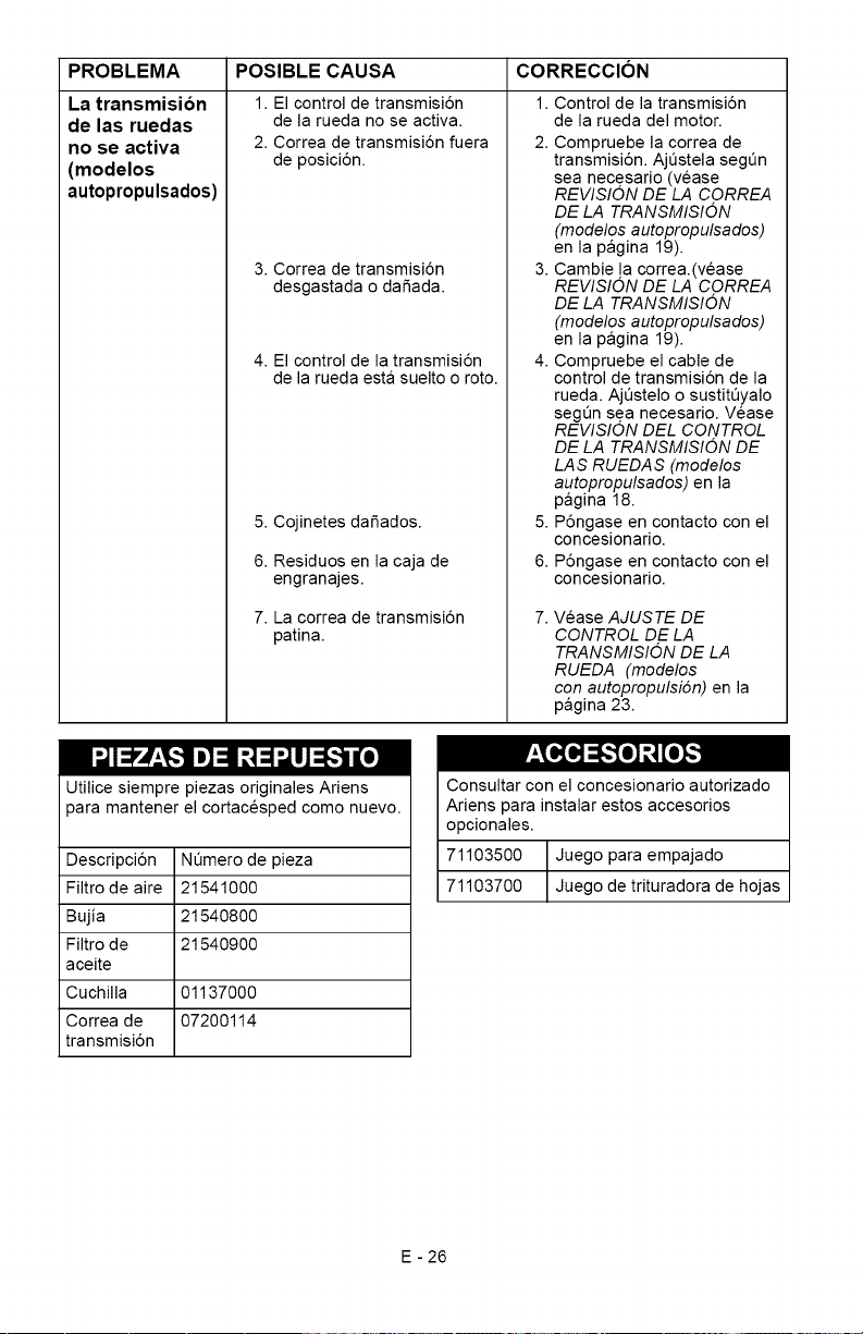
PROBLEMA
La transmision
de las ruedas
no se activa
(modelos
autopropulsados)
POSIBLE CAUSA CORRECCION
1. El control de transmisi6n
de la rueda no se activa.
2. Correa de transmisi6n fuera
de posici6n.
3. Correa de transmisi6n
desgastada o dafiada.
4. El control de la transmisi6n
de la rueda esta suelto o roto.
5. Cojinetes dafiados.
6. Residuos en la caja de
engranajes.
7. La correa de transmisi6n
patina.
1. Control de la transmisi6n
de la rueda del motor.
2. Compruebe la correa de
transmisi6n. AjQstela segQn
sea necesario (vease
REVISION DE LA CORREA
DE LA TRANSMISION
(modelos autopropulsados)
en la pagina 19).
3. Cambie la correa.(vease
REVISION DE LA CORREA
DE LA TRANSMISION
(modelos autopropulsados)
en la pagina 19).
4. Compruebe el cable de
control de transmisi6n de la
rueda. AjQstelo o sustitQyalo
segen sea necesario. Vease
REVISION DEL CONTROL
DE LA TRANSMISION DE
LA S RUEDA S (modelos
autopropulsados) en la
pagina 18.
5. P6ngase en contacto con el
concesionario.
6. P6ngase en contacto con el
concesionario.
Vease AJUSTE DE
CONTROL DE LA
TRANSMISION DE LA
RUEDA (modelos
con autopropulsi6n) en la
pagina 23.
p'z_[_o];_[o],,, ",]
"-]I_.'_,.'_ Im]=11r,,1=1_t_"]il[o]
Utilice siempre piezas originales Ariens
_ara mantener el cortacesped como nuevo.
Descripci6n NQmero de pieza
Filtro de aire 21541000
Bujia 21540800
Filtro de 21540900
aceite
Cuchilla 01137000
Correa de 07200114
transmisi6n
Consultar con el concesionario autorizado
Ariens para instalar estos accesorios
opcionales.
71103500 Juego para empajado
71103700 Juego de trituradora de hojas
E - 26
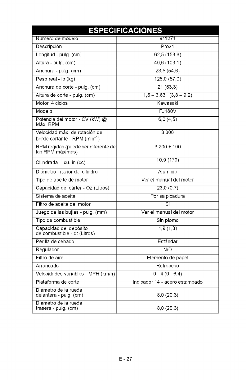
I_,,,,__o,_p_o]_o_[_,,_
Numero de modelo
Descripci6n
Longitud - pulg. (cm)
Altura - pulg. (cm)
Anchura - pulg. (cm)
Peso real- Ib (kg)
Anchura de corte - pulg. (cm)
Altura de corte - pulg. (cm)
Motor, 4 ciclos
Modelo
Potencia del motor - CV (kW) @
Max. RPM
Velocidad max. de rotaci6n del
borde cortante - RPM (min -1)
RPM regidas (puede ser diferente de
las RPM maximas)
Cilindrada - cu. in (cc)
Diametro interior del cilindro
Tipo de aceite de motor
Capacidad del carter - Oz (Litros)
Sistema de aceite
Filtro de aceite del motor
Juego de las bujias - pulg. (mm)
Tipo de combustible
Capacidad del dep6sito
de combustible - qt (Litros)
Perilla de cebado
Regulador
Filtro de aire
Arrancado
Velocidades variables - MPH (km/h)
Plataforma de corte
Diametro de la rueda
delantera - pulg. (cm)
Diametro de la rueda
trasera - pulg. (cm)
911271
Pro21
62,5 (158,8)
40,6 (103,1)
23,5 (54,6)
125,0 (57,0)
21 (53,3)
1,5 - 3,63 (3,8 - 9,2)
Kawasaki
FJ 180V
6,0 (4,5)
3 300
3 200 + 100
10,9 (179)
Aluminio
Ver el manual del motor
23,0 (0,7)
Por salpicadura
Si
Ver el manual del motor
Sin plomo
1,9 (1,8)
Estandar
N/D
Elemento de papel
Retroceso
0- 4 (0- 6,4)
Indicador 14 - acero estampado
8,0 (20,3)
8,0 (20,3)
E - 27
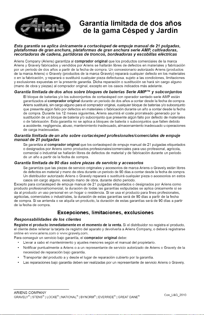
Garantia limitada de dos a os
de la gama Cesped y Jardin
Esta garantia se aplica C/nicamente a cortac_sped de empuje manual de 21 pulgadas,
plataformas de gran anchura, plataformas de gran anchura serie AMP, cultivadoras,
recortadoras de cadena, partidoras de troncos, bordeadoras y escobillas el_ctricas
Ariens Company (Ariens) garantiza al comprador original que los productos comerciales de la marca
Ariens y Gravely fabricados y vendidos pot Ariens se hallaran libres de defectos en materiales y fabricaci6n
pot un periodo de dos afios a partir de la fecha de compra. Un concesionario autorizado Ariens (productos
de la marca Ariens) o Gravely (productos de la marca Gravely) reparara cualquier defecto en los materiales
o en la fabricaci6n, y reparara o sustituira cualquier pieza defectuosa, sujeto alas condiciones, limitaciones
y exclusiones expuestas en la presente garantia. Dicha reparaci6n o sustituci6n se hara sin cargo alguno
(mano de obra y piezas) al comprador original, excepto en los casos indicados mas adelante.
Garantia fimitada de dos a#os sobre bloques de baterias Serie AMP TM y subconjuntos
El bloque de baterias y/o los subconjuntos de cortacesped con operador sentado serie AMP estan
garantizados al comprador original durante un periodo de dos afios a contar desde la fecha de compra.
Ariens sustituira, sin cargo alguno para el comprador original, cualquier bloque de baterias y/o subconjunto
que presente algtJn fallo pot defectos en materiales o fabricaci6n durante un afio a contar desde la fecha
de compra. Durante los 12 meses siguientes, Ariens asumira el coste prorrateado generado pot la
sustituci6n de un bloque de bateria y/o subconjunto que presente algQn fallo por defecto de materiales
o de fabricaci6n. Esta garantia no se aplica a bloques de bateria o subconjuntos que fallen debido
a accidente, negligencia, abuso, mantenimiento inadecuado, almacenamiento inadecuado u operaciones
de carga inadecuadas.
Garantia limitada de un a#o sobre cortac_sped profesionales/comerciales de empuje
manual de 21 pulgadas
Se garantiza al comprador original que los cortacesped de empuje manual de 21 pulgadas etiquetados
o designados pot Ariens como productos profesionales/comerciales para uso profesional, agricola,
comercial o industrial se hallaran libres de defectos de material y de fabricaci6n durante un periodo
de un afio a partir de la fecha de compra.
Garantia fimitada de 90 dias sobre piezas de servicio y accesorios
Se garantiza que las piezas de servicio originales y accesorios de marca Ariens o Gravely estan libres
de defectos en material y mano de obra durante un periodo de 90 dias a contar desde la fecha de compra.
Un distribuidor autorizado Ariens o Gravely reparara o sustituira cualquier pieza o accesorios en estos
casos sin cargo alguno, excepto mano de obra, durante dicho periodo.
Excepto para cortacesped de empuje manual de 21 pulgadas etiquetados o designados pot Ariens como
producto profesional/comercial, la duraci6n de todas las garantias estipuladas se aplica Qnicamente si se
da al producto un uso personal en un hogar o residencia. Si se usa el producto para fines profesionales,
agricolas, comerciales o industriales, la duraci6n de estas garantias sera de 90 dias a partir de la fecha
de compra. Si se arrienda o se alquila un producto, la duraci6n de estas garantias sera de 90 dias a partir
de la fecha de compra.
Excepciones, lirnitaciones, exclusiones
Responsabilidades de los clientes
Registre el producto inmediatamente en el momento de la venta. Si el distribuidor no registra el producto,
el cliente debe rellenar la tarjeta de registro del aparato y devolverla a Ariens Company, o debera registrarse
online en www.ariens.com o www.gravely.com.
Para conseguir un servicio bajo garantia, el comprador original debe:
Llevar a cabo el mantenimiento y ajustes menores segt3n el manual del propietario.
Notificar puntualmente a Ariens o a un representante de servicio autorizado de Ariens o Gravely de la
necesidad de reparaci6n bajo garantia.
Transportar del producto a y desde el lugar de reparaci6n cubierto por la garantia.
Las reparaciones bajo garantia deben ser realizadas pot un representante de servicio Ariens o Gravely.
ARIENS COMPANY
GRAVELY®I STENSC_'I LOCKETS'I NATIONAL®I BYNQRM<_I EVERRIDEC_I GREAT DANEc_' Con L&G 2010
ParaencontrarunrepresentanteautorizadodeserviciotecnicoAriensoGravely,p6ngasecontacto
conAriensen:
655W.RyanStreet
Brillion,WI54110
(920)756-2141
www.ariens.com
www.gravely.com
Excepciones y Limitaciones
Las baterias s61o se garantizan per un periodo de 12 meses a partir de la fecha de compra, en base
a prorrateo. Durante los primeros 90 dias del periodo de garantia, se sustituira una bateria defectuosa
sin cargo alguno. Si el periodo aplicable de garantia supera los 90 dias, Ariens asumira el coste prorrateado
de cualquier bateria defectuosa, hasta Ilegar a los 12 meses a partir de la fecha de la compra. Esta
garantia limitada para baterias no se aplica para bloques de baterias o productos serie AMP.
Exclusiones - Piezas no cubiertas por esta garantia
Los motores y accesorios del motor estan cubiertos s61o per la garantia del fabricante del motor, y no
estan cubiertos pot esta garantia.
Las piezas que no son piezas originales de las marcas Ariens o Gravely no estan cubiertas pot esta
garantia.
Las siguientes piezas de mantenimiento, servicio y recambio no estan cubiertas por esta garantia a
menos que figure en la secci6n Limitaciones anterior: lubricantes, bujias, aceite, filtros de aceite, filtros
de aire, filtros de combustible, guarniciones de frenos, palancas del freno, zapatas, guias, cuchillas
raspadoras, pernos de seguridad, cuchillas del cortacesped, aspas del cortacesped, brazos, escobillas,
faros delanteros, bombillas, cuchillos, cuchillas.
Cualquier defecto que sea resultado del use indebido, alteraci6n, montaje incorrecto, negligencia
o accidente que requiera reparaci6n, no esta cubierto por esta garantia.
Esta garantia s61o aplica a productos adquiridos en Estados Unidos (incluyendo Puerto Rico) y Canada.
En el resto de paises, p6ngase en contacto con el punto de compra para obtener informaci6n sobre
la garantia.
Renuncia
Ariens puede modificar con cierta frecuencia el disefio de sus productos. Nada incluido en esta garantia se
interpretara de ta! modo que obligue a Ariens Company a incorporar tales cambios de disefio en los productos
fabricados previamente, ni se interpretaran tales cambios como una admisi6n de que tales disefios eran
defectuosos.
LIMITA ClON DE REMEDIOS Y DAKIOS
La responsabilidad de Ariens Company bajo esta garantia y bajo cualquier garantia implicita que pueda existir
se limita a la reparaci6n o sustituci6n de cualquier defecto de fabricaci6n, y a la reparaci6n o sustituci6n
de cualquier pieza defectuosa. No podra hacerse responsable a Ariens Company de ningt3n dafio fortuito,
especial o indirecto (incluyendo la perdida de beneficios). AIgunos Estados no permiten la exclusi6n
de dafios fortuitos o indirectos, pot Io que la anterior limitaci6n podria no aplicarse a usted.
RENUNCIA DE GARANTiA ADICIONAL
Ariens Company no proporciona ninguna garantia, expresa o implicita, aparte de la expuesta de
manera expresa en la presente garantia. Si las leyes de su Estado determinan la aplicacibn a Ariens
de una garantia implicita de aptitud o de idoneidad para un prop6sito particular, o de cualquier otro
tipo de garantia implicita, dicha garantia implicita estar_ limitada a la duraci6n de la presente garantia.
Algunos Estados no permiten Iimitaciones a la duracibn de dichas garantias implicitas, por Io que
la anterior limitacibn podria no aplicarse a usted.
Esta garantia le proporciona derechos legales especificos y puede tener tambien otros derechos que varian
de Estado a Estado.
ARIENS COMPANY
GRAVELY®I STENSC_'I LOCKETS'I NATIONAL®I BYNQRM<_I EVERRIDEC_I GREAT DANEc_' Con L&G 2010

Ariens Company
655 West Ryan Street
Brillion, WI 54110-1072
920-756-2141
Fax 920-756-2407
www.ariens.com
A WARNING A
The engine exhaust from this product
contains chemicals known to the State
of California to cause cancer, birth
defects or other reproductive harm.