
Safetyo Assembly o Operation oTips & Techniques oMaintenance * Troubleshooting o Parts Lists oWarranty
®
Transmatic Lawn Tractor -- Model Series 77T
READ SAFETY RULES AND mNSTRUCTmONS CAREFULLY BEFORE OPERATmON
Warning: This unitis equippedwithan internalcombustionengineandshouldnot beusedon or nearany unimprovedforest-covered,brush=
coveredor grass=coveredlandunlessthe engine'sexhaustsystemis equippedwitha sparkarrestermeetingapplicablelocalorstate laws(if any),
If a sparkarresteris used,it shouldbemaintainedineffectiveworkingorderby the operator,Inthe Stateof Californiathe aboveis requiredbylaw
(Section4442of the CaliforniaPublicResourcesCode),Otherstatesmayhavesimilarlaws,Federallawsapplyonfederallands,A sparkarrester
for the muffleris availablethroughyournearestengineauthorizedservicedealeror contactthe servicedepartment,RO,Box361131Cleveland,
Ohio44136=0019,
FORMNO,769=02243A
PRINTEDiN U,S,A Troy-Bilt LLC, P.O. BOX 361131 CLEVELAND, OHiO 44136-0019 01/2006
This Operator's Manua_ is an important part of your new lawn tractor, mtwH_ he_p you assemble,
prepare and maintain the unit for best performance. P_ease read and understand what it says.
Table of Contents
S_ope Gauge ....................................................... 3
Safe Operation Practices ................................... 4
Setting Up Your Lawn Tractor ............................ 8
Operating Your Lawn Tractor ........................... 10
Adjusting Your Lawn Tractor ............................ 16
Maintaining Your Lawn Tractor ........................ 18
Off-Season Storage / Attachments ................. 24
Safety Labems .................................................... 25
TrouMe Shooting .............................................. 26
Parts List ........................................................... 28
Notes .................................................................. 44
California Emission Contro_ Warranty ............ 47
Warranty ............................................ Back Cover
Finding and Recording Model Number
BEFOREYOU START ASSEMBLING
YOUR NEW EQUIPMENT,
please locatethe model plate on the equipment and copy the
information to the sample model plate providedto the righL
You can locate the model plate by looking beneathe the seal
This information will be necessary to use the manufacturer's
web site and/or obtain assistance from the Customer Support
Department or an authorized service dealer.
Modem Number Seriam Number
0 TR#_H_-T_ TROY-B|LT LLC
P. O. BOX 361131
www.troybimt.com CLEVELAND, ON 44136
338-558-7228
,, 856-848-6483_
Customer Support
P_ease do NOTreturn the unit to the retai_er from which it was
purchased, without first contacting Customer Support.
If you have difficulty assembling this product or have any questions regarding the controls, operation, or maintenance of this
unit, you can seek help from the experts. Choose from the options below:
1, VisittroybHt.com for manyusefulsuggestions,Clickon Customer
Supportbuttonandyouwill get the optionsreproducedin thescreen
shotbelow,Click onthe appropriatebuttonandhelpis immediately
available,
3, The engine manufacturer is responsibleforall engine-relatedissues
with regardto performance,power-rating,specifications,warrantyand
service,Pleasereferto the enginemanufacturer'sOwner's/Operator's
Manual,packedseparatelywithyour unit,for moreinformation,
2, Phonea Customer Support Representative at 1-866-840-6483,
2
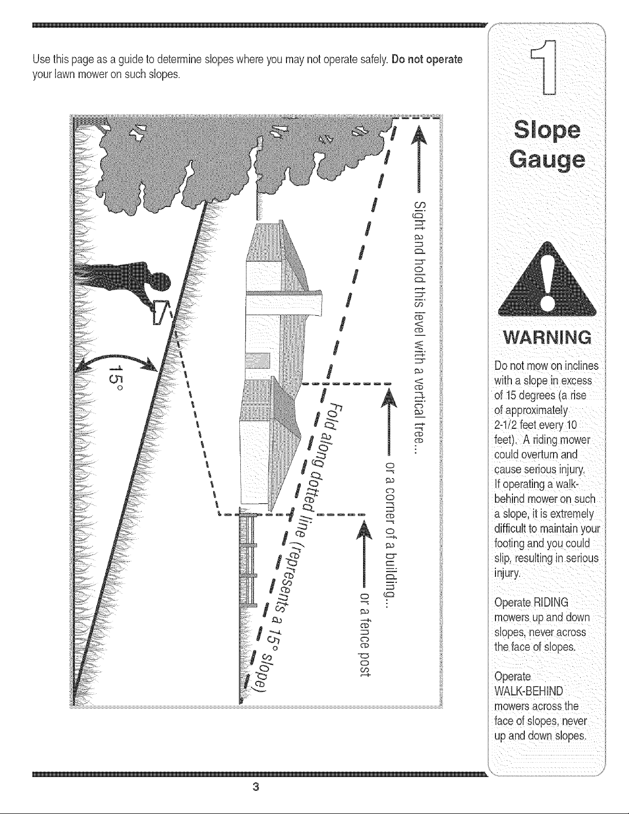
yourlawnmoweronsuchslopes.
/
/
/
/
o
/
/
t
o
w_
WARNING
Do not mowon inclines
with a dope in excess
of 15 degrees (a rise
of approximately
2-"
feet). A riding r
could overturn and
cause serious injury.
if operating a walb
behind mower on such
a dope, it is extremely
footing and you could
dip, resulting in serious
injury.
Operate RiDiNG
mowers up and down
dopes, neveracross
the face of dopes.
Operate
WALK-BEHIND
mowers across the
face of dopes, never
up and down slopes.
\
3
_i i _ i _i _ i _ iii _ _
DANGER: This machine was built to be operated according to the rubs for safe operation in this
manuak As with any type of power equipment, carelessness or error on the part of the operator can
S ale result in serious injury.This machine is capable of amputating hands and feet and throwing objects.
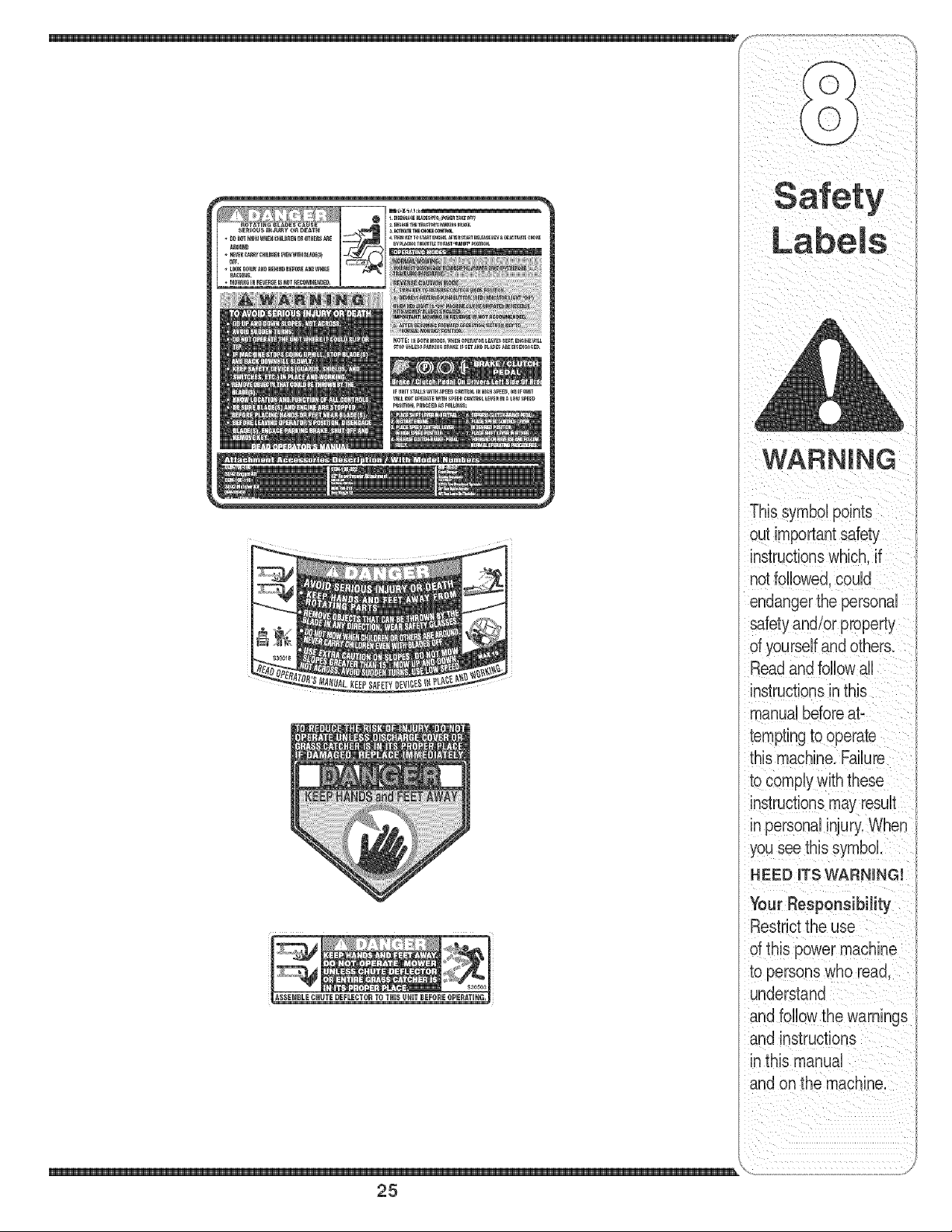
Failureto observe the following safety instructions could result in serious injury or death.
instructionswhich, if
notfollowed, could
endangerthe personal
safety and/or property
of yourself and others.
Read and fobow all
instructionsin this man=
ual before attemptingto
operatethis machine.
Failureto comply with
When you see this
symbol.
H EED ITS WARNING
Your
Responsibility
Restrictthe use
of this power machine
to persons who read.
understand
and follow the warnings
and instructions
in this manual
Children
1, Tragicaccidentscan occurif the operatoris not
abrt tothe presenceof children,Childrenare often
attractedto the machineandthe mowingactivity,
Theydo not understandthe dangers,Neverassume
thatchildrenwill remainwhereyou lastsawthem,
a, Keepchildrenout of the mowingarea andin
watchfulcare of a responsibleadult otherthan
the operator,
b, Be alert and turn machineoff if a childenters
the area,
c, Beforeandwhile backing,lookbehindand
downfor smallchildren,
d, Nevercarrychildren,evenwiththe blade(s)
shutoff,Theymayfalloffandbeseriously
iniuredor interferewithsafemachineoperation,
e, Use extremecarewhenapproachingblind
corners,doorways,shrubs,treesor other
objectsthatmayblockyourvisionof a child
who mayruninto the machine,
f, To avoid back-overaccidents, always
disengage the cutting blade(s) before
shifting into Reverse.If equipped, the
"Reverse Caution Mode" should not be
used when children or others are around.
g, Keepchildrenaway from hotor running
engines,Theycansuffer burnsfroma hot
muffler,
h, Removekeywhen machineis unattendedto
preventunauthorizedoperation,
2, Neverallowchildrenunder14yearsoldto operate
the machine,Children14}'earsold and overshould
readandunderstandthe operationinstructionsand
safetyrubs in this manualand shouldbe trainedand
supervisedbya parent,
Operation
Safe Handling of Gasoline:
1. Toavoid personal injuryor property damage use
extreme care in handlinggasoline. Gasoline is
extremely flammable and the vapors areexplo-
sive. Seriouspersonaliniurycanoccurwhengasoline
is spilledonyourselfor yourclotheswhichcan ignite,
Washyourskinandchangeclothesimmediately,
a, Use onlyan approvedgasolinecontainer,
b, Neverfill containersinsidea vehbb or ona
truckor trailerbedwitha plastb liner,Always
placecontainerson the groundawayfrom
yourvehble beforefilling,
c, When practbal, removegas-powered
equipmentfromthe truck ortrailerand refuelit
onthe ground,Ifthis is not possibb, then
refuelsuchequipmentona trailerwitha
portabb container,ratherthan fromagasoline
dispensernozzb,
d, Keepthe nozzb in contactwiththe rimof
the fueltankor containeropeningat all
timesuntilfuelingis complete,Donot usea
nozzleIocbopendevice,
e, Extinguishall cigarettes,cigars,pipesand
othersourcesof ignition,
f, Neverfuel machineindoors,
g, Neverremovegas cap or add fuel whilethe
engineis hot or running,Mow engineto cool
at bast twominutesbeforerefueling,
h, Neveroverfill fuel tank,Fill tank to no more
than1/2inchbelowbottomof filbr neckto
allowspacefor fuel expansion,
i, Replacegasolinecapandtightensecurely,
i, If gasolineis spilled,wipe it offthe engine
andequipment,Moveunitto anotherarea,
Wait5 minutesbeforestartingthe engine,
k, To reducefire hazards,keepmachinefreeof
grass,leaves,orother debrisbuild-up,Clean
upoil orfuel spillageand removeany fuel
soakeddebris,
I, Neverstorethe machineor fuel container
insidewherethere is anopenflame,spark
or pilotlightas on a waterheater,space
heater,furnace,clothesdryeror othergas
appliances,
m, Allowa machineto cool at bast fiveminutes
beforestoring,
4
GeneralOperation:
1. Read,understand,and followall instructionson the
machineandinthe manual(s)beforeattemptingto
assembleandoperate.Keepthismanualina safe
placefor futureandregularreferenceandforordering
replacementparts.
2. Befamiliarwithall controlsandtheirproperoperation.
Knowhow to stopthe machineanddisengagethem
quickly.
3. Neverallowchildrenunder14yearsold to operate
this machine.Children14yearsold andovershould
readandunderstandthe operationinstructionsand
safetyrubs in thismanualandshouldbetrainedand
supervisedby aparent.
4. Neverallowadultsto operatethis machinewithout
properinstruction.
5. To helpavoid bladecontactor a thrownobiect iniury,
keepbystanders,helpers,childrenand petsat bast
75 feetfromthe machinewhileit is inoperation.8top
machineif anyoneentersthe area.
6. Thoroughlyinspectthearea wherethe equipmentis to
beused.Removeallstones,sticks,wire,bones,toys,
andotherforeignobiectswhichcould bepickedup
andthrownbythe blade(s).Thrownobiectscancause
seriouspersonaliniury.
7, Planyourmowingpatternto avoiddischargeof
materialtowardroads,sidewalks,bystandersandthe
like.Also,avoiddischargingmaterialagainsta wall or
obstructionwhichmaycausedischargedmaterialto
ricochetbacktowardthe operator.
8. Alwayswearsafety glassesor safetygogglesduring
operationandwhile performingan adiustmentor
repairto protectyour eyes.Thrownobiectswhich
ricochetcan causeseriousiniuryto the eyes.
9. Wearsturdy,rough-sobdworkshoes and close-fitting
slacksandshirts.Loosefittingclothesandiewelry
can becaughtinmovabbparts. Neveroperatethis
machinein barefeetor sandals.
10.Beawareof the mowerandattachmentdischarge
directionanddo notpoint it at anyone.Do notoperate
the mowerwithoutthe dischargecoverorentiregrass
catcherin itsproperplace.
11.Do notput handsor feetnearrotatingpartsor under
the cuttingdeck.Contactwiththe blade(s)can
amputatehandsandfeet.
12.Amissingor damageddischargecovercan cause
bladecontactor thrownobiectiniuries.
13.8topthe blade(s)whencrossinggraveldrives,walks,
or roadsandwhilenot cuttinggrass.
14.Watchfor trafficwhenoperatingnearor crossing
roadways.Thismachineis not intendedfor useon
anypublic roadway.
15.Do notoperatethe machinewhileunderthe influ-
enceof alcoholordrugs.
16.Mowonly in daylightor goodartificiallight.
17,Nevercarrypassengers.
18.Disengageblade(s)beforeshiftinginto reverse.
Backupslowly.Alwayslookdownandbehindbefore
andwhilebackingto avoida back-overaccident.
19.Slowdownbeforeturning.Operatethe machine
smoothly.Avoiderraticoperationandexcessive
instructions wh ch. if
not followed, could
endanger the personal
safety and/or property
of yourself and others.
Read and follow all
instructions in this man-
ual before attempting to
operatethis machine.
these instructions may
result in personal injury.
When you see this
symbol.
HEED iTS WARNING
Your
Responsibility
Restrictthe use
d this power machine
to persons who read,
understand
and follow the warninas
and instructions
in this manual
5
21.Neverleavea runningmachineunattended.Always
turnoff blade(s),placetransmissionin neutral,set
parkingbrake,stopengineand removekeybefore
dismounting.
22.Useextracare whenloadingor unloadingthe
machineintoa trailerortruck.Thisunitshould not
bedrivenupor downramp(s),becausethe unit
couldtip over,causingseriouspersonaliniury.The
unit mustbepushedmanuallyonramp(s)to loador
unloadproperly.
23.Mufflerandenginebecomehotandcan causea
burn.Do nottouch.
24.Checkoverheadclearancescarefullybeforedriving
underlowhangingtreebranches,wires,dooropen-
ingsetc. wheretheoperatormaybe struckor pulled
fromthe unit,whichcouldresultinseriousiniury.
25.Disengageallattachmentclutches,depressthe
brakepedalcompbtelyandshift into neutralbefore
attemptingto startengine.
26.Yourmachineis designedto cutnormalresidential
grassof aheightno morethan 10".Do notattemptto
mowthroughunusuallytall,dry grass(e.g.,pasture)
or pilesof dry leaves.Drygrassor leavesmay
contactthe engineexhaustand/orbuildup onthe
mowerdeckpresentinga poten%l fire hazard.
27.Useonlyaccessoriesandattachmentsapprovedfor
thismachineby the machinemanufacturer.Read,
understandandfollowall instructionsprovidedwith
the approvedaccessoryor attachment.
28.Dataindicatesthatoperators,age60 yearsand
above,areinvolvedin a largepercentageof riding
mower-relatediniuries.Theseoperatorsshould
evaluatetheirabilityto operatetheridingmower
safelyenoughto protectthemselvesandothersfrom
seriousiniury.
29.If situationsoccurwhicharenot coveredinthis
manual,usecareandgoodiudgment.Contactyour
customerservicerepresentativefor assistance.
WARNING
This symbol points
speed. }
20.Dbengageblade(s),setparkingbrake,stopengine
andwaituntilthe blade(s)cometo acompletestop
beforeremovinggrasscatcher,emptyinggrass,
uncloggingchute,removingany grassor debris,or
makinganyadiustments.
Slope Operation:
Slopesarea majorfactorrelatedto lossof controland
tip-overaccidentswhichcan resultin severeinjury or
death,All slopesrequireextracaution,if you cannot
backupthe slopeor if youfeel uneasyonit, do notmow
it,
Foryour safety,usethe slopegaugeincludedas partof
thismanualto measureslopesbeforeoperatingthisunit
ona slopedor hillyarea,if the slopeis greaterthan 15
;_,_ degreesas shownonthe slopegauge,do notoperate
,, thisunit onthatareaorseriousinjurycouldresult,
uperal:lon Do:
1, Mow up and downslopes,notacross,Exercise
racl:lces extremecautionwhenchangingdirectiononsbpes,
2, Watchfor hobs, ruts,bumps,rocks,or other hidden
objects,Uneventerraincouldoverturnthe machine,
out important safety
instructions which, if
not followed, could
endangerthe personal
safety and/or property
of yourself and others.
Readand follow all
instructions in this man°
ual before attempting to
Tallgrasscan hideobstacbs,
3, Use slow speed,Choosea low enoughspeed
settingso thatyouwill not haveto stoporshift while
onthe slope,Tiresmaylosetractiononslopeseven
thoughthe brakesarefunctioningproperly,Always
keepmachineingearwhengoingdownslopesto
takeadvantageof enginebrakingaction,
4, Followthe manufacturer'srecommendationsfor
wheelweightsorcounterweightsto improvestability,
5, Use extra carewith grasscatchersor otherat-
tachments,Thesecanchangethe stabilityof the
machine,
6, Keepall movementon theslopes slow and gradual
Do not makesuddenchangesinspeedor direction,
Rapidengagementor brakingcouldcausethe front
of the machineto liftand rapidlyfib overbackwards
whichcouldcauseseriousinjury,
7, Avoidstartingor stoppingon a slope,If tires lose
traction,disengagethe blade(s)andproceedslowly
straightdownthe slope,
Do Not:
1, Do notturn on slopes unlessnecessary;then,turn
slowlyandgraduallydownhill,if possibb,
2, Do not mownear drop-offs,ditchesor embankments,
The mowercouldsuddenlyturnoverif awheel is over
the edgeof acliff,ditch,or if anedgecavesin,
3, Do nottry to staNlizethe machineby puttingyourfoot
onthe ground,
4, Do not usea grasscatcheron steep slopes,
5, Do not mowon wet grass,Reducedtractioncould
causesliding,
6, Do notshift to neutraland coastdownhill Over-speed-
ingmaycausethe operatorto lose controlof the
machineresultingin seriousinjuryordeath,
7, Do nottow heavypull behindattachments(e,g,loaded
dumpcart, lawnroller,etc,)on slopesgreaterthan
5 degrees,Whengoingdown hill,the extraweight
tendsto pushthetractorand maycauseyou to loose
control (e,g,tractormayspeedup, brakingandsteer-
ingabilityarereduced,attachmentmayjack-knifeand
causetractorto overturn),
Towing:
1, Towonlywith a machinethat hasa hitchdesignedfor
towing,Do not attachtowedequipmentexceptat the
hitchpoint,
2, Followthe manufacturersrecommendationfor weight
limitsfor towedequipmentandtowingonslopes,
3, Neverallowchildrenor othersin or on towedequip-
ment,
4, On slopes,theweight of thetowed equipmentmay
causelossof tractionandlossof control,
5, Travelslowlyand allowextra distanceto stop,
6, Do notshift to neutraland coastdownhill
these instructions may
result in personal injury,
When you see this
symbol
HEED ITS WARNING
YOUr
Responsibility
Restrictthe use
of this power machine
to persons who read.
understand
and follow the warnings
and instructions
in this manual
6
Service lO,Neverattemptto makeadiustmentsor repairsto the
1. Neverrun an engineindoorsor in a poorlyventilated
area. Engineexhaustcontainscarbonmonoxide,an
odorless,anddeadlygas.
2. Beforecleaning,repairing,or inspecting,makecertain
the blade(s)andall movingpartshavestopped.
Disconnectthe sparkplugwireandgroundagainstthe
engineto preventunintendedstarting.
3. Periodicallycheckto makesurethe bladescometo
compbte stopwithinapproximately(5) fiveseconds
afteroperatingthe bladedisengagementcontrol,if the
bladesdo notstopwithinthethis timeframe,your unit
shouldbeservicedprofessionallyby anauthorized
MTDServiceDealer.
4. Checkbrakeoperationfrequentlyas it is subiectedto
wearduringnormaloperation.Adiustandserviceas
required.
5. Checkthe blade(s)and enginemountingboltsat
frequentintervalsfor propertightness.Also,visually
inspectblade(s)for damage(e.g. excessivewear,
bent,cracked). Replacethe blade(s)with theoriginal
equipmentmanufacturer's(O.E.M.)blade(s)only,
listedin thismanual."Useof partswhichdonot meet
the originalequipmentspecificationsmaybad to
improperperformanceandcompromisesafety!"
6. Mowerbladesaresharp.Wrapthe bladeor wear
gloves,anduseextracautionwhenservicingthem.
7, Keepall nuts,bolts,andscrewstight to besurethe
equipmentis insafeworkingcondition.
8. Nevertamperwiththe safetyinterlocksystemor other
safetydevices.Checktheir properoperationregularly.
9. After strikinga foreignobiect,stop the engine,
disconnectthe sparkplugwire(s)and groundagainst
the engine.Thoroughlyinspectthe machinefor any
damage.Repairthe damagebeforestartingand
operating,
machinewhile theengineis running,
11,Grasscatchercomponentsandthe discharge
coveraresubiectto wearanddamagewhichcould
exposemovingpartsor allowobiectsto bethrown,
Forsafetyprotection,frequentlycheckcomponents
ii
andreplaceimmediatelywithoriginalequipment
manufacturer's(O,E,M,)parts only,listed in this
manual,"Useof partswhichdo notmeettheoriginal
equipmentspecificationsmaybad to improper
performanceandcompromisesafety!"
12,Do notchangethe enginegovernorsettingsor
over-speedthe engine,The governorcontrolsthe
maximumsafeoperatingspeedof theengine,
13,Maintainor replacesafetyandinstructionlabels,as
necessary,
14,Observeproperdisposallawsandregulationsfor
gas,oil,etc, to protecttheenvironment,
i /
This symbol points
instructions which, if
safety and/or property
of yourself and others,
Readand follow al
ual before attempting to
operatethis machine.
When you see this
symbol,
N EED roTSWARNING
Your
Responsibility
Restrictthe use
of this power machine
to persons who read,
understand
>wthe warnings
and instructions
in this manual
\
7
WARNING
Use extreme care when
handling gasoline.
Gasoline is e×tremeiy
flammable and the
vapors are explosive.
Never fuel machine
indoors or while the en-
gine is hot or runmng,
Extinguish cigarettes,
cigars, pi Des.and other
sources of ignition.
Make sure the riding
mower's engine is off.
remove the ignition
key, and set the parking
brake before removing
the shipping brace,
The shipping brace,
used for packaging
purposes only, must be
removed and discarded
before operating your
riding mower.
The mowing deck is
capable of throwing
objects. Failure to oper-
ate the riding mower
without the discharge
cover in the proper
operating position
coumdresumtm serious
personal injury and/or
property damage.
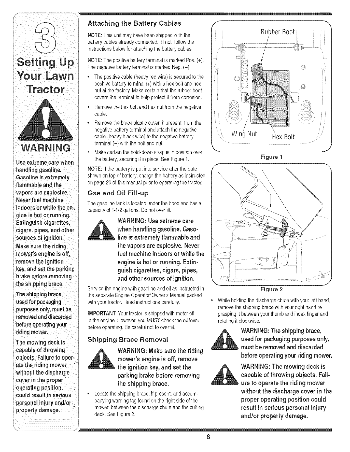
Attaching the Battery Cables ",
NOTE:This unitmayhavebeenshippedwiththe Rubber Boot
batterycanes alreadyconnected, If not,followthe .......
instructionsbelowfor attachingthe batterycanes,
NOTE:The positivebatteryterminalis markedPos,(+),
The negativebatteryterminalis markedNeg,(-),
• Thepositivecane (heavyredwire) is securedto the
positivebatteryterminal(+)witha hexbolt andhex
nut at thefactory,Makecertainthatthe rubberboot
coversthe terminalto helpprotectit from corrosion,
• Removethehex bolt andhexnut fromthe negative
cane,
• Removetheblackplasticcover,if present,from the
negativebatteryterminalandattachthe negatkle
cable(heavyblackwire)to the negativebattery
terminal(-) withthe boltandnut,
. Makecertainthehold=downstrapis in positionover
the battery,securingit inplace,See Figure1,
NOTE:if the batteryis putinto serviceafterthe date
shownontop of battery,chargethe batteryas instructed
on page20of this manualprior to operatingthetractor,
Gas and Oi_ Fill°up
The gasolinetankis locatedunderthe hood and hasa
capacityof 1=1/2gallons,Do notoverfill
WARNING: Use extreme care
when handling gasoline. Gaso°
line is extremely flammable and
the vapors are explosive. Never
fuel machine indoors or while the
engine is hot or running. Extin-
guish cigarettes, cigars, pipes,
and other sources of ignition.
Servicethe enginewithgasolineand oil as instructedin
the separateEngineOperator/Owner'sManualpacked
withyourtractor,Readinstructionscarefully,
IMPORTANT:Yourtractoris shippedwith motoroil
inthe engine,However,you MUSTcheckthe oillevel
beforeoperating,Becarefulnot to overfill
Shipping Brace Removal
WARNING: Make sure the riding
mower's engine is off, remove
the ignition key, and set the
parking brake before removing
the shipping brace.
. Locatethe shippingbrace,if present,and accom=
panyingwarningtag foundonthe rightside of the
mower,betweenthe dischargechuteandthe cutting
deck,SeeFigure2,
/
Win Nut Hex Bolt ,>,
Figure 1
J
Figure 2
Whileholdingthedischargechutewith yourleft hand,
removethe shippingbracewithyour righthandby
graspingit betweenyourthumband indexfingerand
rotatingit clockwise,
WARNING:The shipping brace,
used for packaging purposes only,
must be removed and discarded
before operating your riding mower.
WARNING: The mowing deck is
capable of throwing objects. Fail-
ure to operate the riding mower
without the discharge cover in the
proper operating position could
result in serious personal injury
and/or property damage.
8
Attaching The Steering Whee_
Jfthe steeringwheelfor yourtractordid notcome
attached,the hardwarefor attachingit hasbeenpacked
withinthe steeringwheel,beneaththe steeringwheel
cap,Carefullypry off thesteeringwheelcapand remove
the hardware,
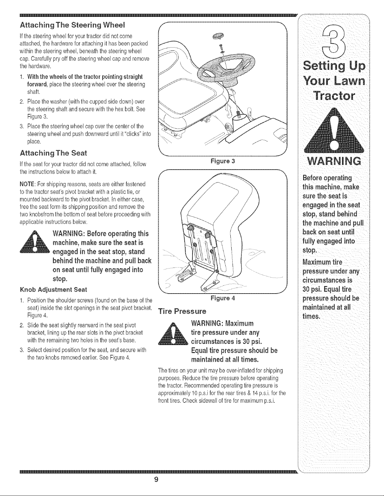
1, With the wheels of the tractor pointing straight
forward, placethe steeringwheeloverthe steering
shaft,
2, Placethe washer(withthecuppedside down)over
the steeringshaftandsecurewith the hex bolt, See
Figure3,
3, Placethe steeringwheelcap overthe centerof the
steeringwheelandpushdownwarduntilit"clicks" into
place,
Attaching The Seat
Jfthe seatfor yourtractordid not comeattached,follow
the instructionsbelowto attach it,
NOTE:For shippingreasons,seatsareeitherfastened
to the tractorseat'spivotbracketwitha plastictie,or
mountedbackwardto the pivotbracket,In eithercase,
free theseatform its shippingpositionand removethe
two knobsfromthe bottomof seatbeforeproceedingwith
applicableinstructionsbelow,
WARNING: Before operating this
machine, make sure the seat is
engaged in the seat stop, stand
behind the machine and puiJ back
on seat until fuJJyengaged into
stop.
Knob Adjustment Seat
1, Positionthe shoulderscrews(foundon the baseof the
seat)insidethe slot openingsin theseat pivotbracket,
Figure4,
2, Slidethe seatslightlyrearwardin the seat pivot
bracket,liningupthe rearslotsin the pivotbracket
withthe remainingtwoholesin the seat'sbase,
3, Selectdesiredpositionfor the seat,andsecurewith
the two knobsremovedearlier,SeeFigure4,
Figure 3
Figure 4
Tire Pressure
WARNING: Ma×imum
tire pressure under any
circumstances is 30 psi.
Equal tire pressure shouJd be
maintained at all times.
The tireson yourunit maybe overdnflatedforshipping
purposes,Reducethe tire pressurebeforeoperating
the tractor,Recommendedoperatingtirepressureis
approximately10p,s,iforthe reartires& 14 p,s,kfor the
fronttires,Checksidewallof tire for maximump,s,k
Settin¢
WARNING
Before operating
this machine, make
sure the seat is
engaged in the seat
stop, stand behind
the machine and puJJ
back on seat untiJ
fully engaged into
stop.
Ma×imum tire
pressure under any
circumstances is
30 psi. EquaJtire
pressure shouJd be
maintained at aJJ
times.
\
9
NOTE:Anyreference
inthismanualtothe
RIGHTorLEFTsideof
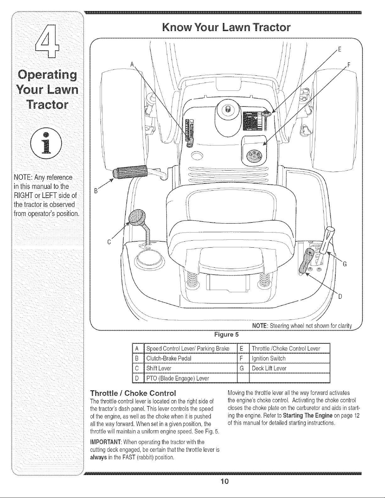
Know Your Lawn Tractor
Figure 5
A SpeedControlLever/ParkingBrake E Throttle/ChokeControlLever
B Clutch-BrakePedal F IgnitionSwitch
C ShiftLever G DeckLift Lever
D PTO(BladeEngage)Lever
Throttle / Choke Control
Thethrottlecontrolleveris locatedon the rightside of
thetractor'sdash panel Thislevercontrolsthe speed
of the engine,as wellas the chokewhen it is pushed
allthe wayforward,Whensetin a given position,the
throttb will maintaina uniformenginespeed,SeeFig, 5,
IMPORTANT:Whenoperatingthe tractorwith the
cuttingdeckengaged,be certainthat the throttb bver is
always in the FAST(rabbit)position,
Movingthethrottle bver all thewayforwardactivates
the engine'schokecontrol Activatingthe chokecontrol
doses thechokeplateon the carburetorand aids in start-
ingthe engine,Referto Starting The Engine on page 12
of thismanualfor detailedstartinginstructions,
/
10
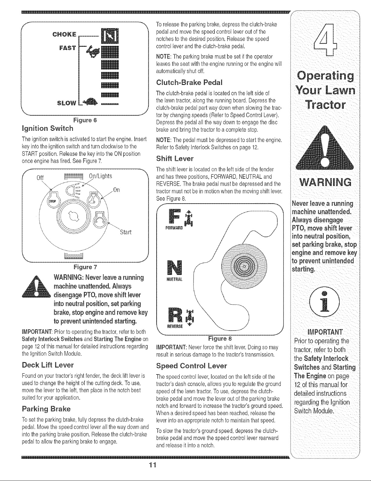
Figure 6
ignition Switch
Theignitionswitchis activatedto startthe engine,Insert
keyintothe ignitionswitchandturnclockwisetothe
STARTposition,Releasethe keyintothe ON position
onceenginehasfired. See Figure7.
Off hts
\
Start
Figure 7
WARNING: Never leavea running
machine unattended. Nways
disengage PTO,move shift Jever
into neutral position, set parking
brake, stop engine and remove key
to prevent unintended starting.
IMPORTANT:Priorto operatingthe tractor,referto both
Safety interlock Switches and Starting The Engine on
page12of this manualfor detailedinstructionsregarding
the IgnitionSwitchModule.
Deck Lift Lever
Foundon yourtractor'srightfender,thedecklift leveris
usedto changethe heightof the cuttingdeck.To use,
movethe leverto the left, thenplacein the notchbest
suitedfor yourapplication.
Parking Brake
Tosetthe parkingbrake,fullydepressthe dutch=brake
pedal.Movethe speedcontrol leverall the waydownand
intothe parkingbrakeposition.Releasethe clutch=brake
pedalto allowthe parkingbraketo engage.
leavesthe seatwith theenginerunningor the enginewill
automaticallyshutoff.
Clutch-Brake Pedal
The clutch=brakepedal is locatedon theleft sideof
the lawntractor,alongthe runningboard.Depressthe
clutch=brakepedalpart waydownwhenslowingthe trac-
tor by changingspeeds(Referto SpeedControlLever).
Depressthe pedal all the way downto engagethedisc
brakeandbring thetractorto a completestop.
NOTE:The pedalmust be depressedto start theengine.
Referto SafetyInterlockSwitcheson page12.
Shift Lever
The shift leveris locatedon the left side of the fender
andhas threepositions,FORWARD,NEUTRALand
REVERSE.The brakepedalmustbedepressedandthe
tractormustnot be in motionwhenthe movingshift lever.
SeeFigure8.
f
FORtNARB
NgET_L
REVERSE
x..
Figure 8
IMPORTANT:Neverforcethe shift lever.Doingso may
resultinseriousdamageto thetractor'stransmission.
Speed Contro_ Lever
The speedcontrol lever,locatedon the left side of the
tractor'sdashconsole,allowsyou to regulatethe ground
speedof the lawntractor.To use, depressthe clutch=
brakepedaland movethe leverout of the parkingbrake
notchandforwardto increasethe tractor'sgroundspeed.
Whena desiredspeed hasbeen reached,releasethe
leverinto anappropriatenotchto maintainthat speed.
Toslowthe tractor'sgroundspeed,depressthe clutch=
brakepedaland movethe speedcontrol leverrearward
andreleaseit into a notch.
11
machine unattended.
PTO, move Shift lever
into neutralposition,
set parking brake, Stop
engine and remove ke_]
to prevent unintended
the Safety interlock
Switches and Starting
_,o iiiiiiiiiiiiiii _/

WARNING
Do not operate
the tractor if the
interlock system is
malfunctioning. This
system was designed
for your safety and
protection.
Keep hands and
feet away from the
discharge opening of
the cutting deck,
Do not operate
the tractor if the
interbck systemis
malfunctioning. This
system was designed
for your safety and
protection.
if you strike a foreign
object, stop the
engine, disconnect
the spark plug
wire(s) and ground
against the engine.
Thoroughly inspect
the machine for any
damage. Repair
the damage before
restarting and
operating,
PTO (B_ade Engage) Lever
Foundon the tractor'srightfender,the
PTO(bladeengage)leveris usedto
engagepowerto the cuttingdeck or
other(separatelyavailable)attach-
ments,To operate,movethe leverall
thewayforward,Movingthe leverall
thewayrearwardinto the PTOOFF
positiondisengagespowerto the
cuttingdeck/attachment,
NOTE:The PTO(bladeengage)lever
mustbe inthe disengaged(PTOOFF)
positionwhenstartingtheengine,
Safety hteHock Switches
z
o
_3
i4
_s
Thistractoris equippedwitha safetyinterlocksystem
for the protectionof the operator,If the interlocksystem
shouldever malfunction,do not operatethe tractor,
ContactanauthorizedTroybiltservicedealer,
, The safety interlocksystempreventstheengine
fromcrankingor startingunlessthe parkingbrakeis
engaged,and the PTO(BladeEngage)leveris in the
disengaged(OFF)position,
• The engine willautomaticallyshut off if the operator
leavestheseat beforeengagingthe parkingbrake,
• The engine willautomaticallyshut off if the operator
leavesthetractor'sseatwiththe PTO(BladeEn=
gage)leverin the engaged(ON)position,regardless
of whethertheparkingbrakeis engaged,
• The engine willautomaticallyshut off if the operator
engagesthe PTOwith the parkingbrakeON,
• The engine willautomaticallyshut off if the PTO
(BladeEngage)leveris movedintothe engaged
(ON)positionwiththeshift leverin Reverse,
WARNING: Do not operate the
tractor if the interlock system is
malfunctioning. This system was
designed for your safety and
protection.
Engaging the Parking Brake
Toengagethe parkingbrake:
1, Fullydepressthe clutch-brakepedaland hold it
downwithyourfoot,
2, Movethe speedcontrolleverall the way downand
intothe parkingbrakeposition,
3, Releasethe clutch-brakepedalto allowthe parking
braketo engage,
Toreleasethe parkingbrake:
1, Depressthe clutch-brakepedal and movethe speed
controlleveroutof the parkingbrakepositionand
intoa desiredspeed,
Setting the Cutting Height
1, Selectthe heightpositionof the cuttingdeck by placing
the deck lift leverin anyof thesixdifferentcutting
heightnotcheson the right sideof the fender,
WARNING: Keep hands and feet
away from the discharge opening
of the cutting deck.
Referto Leveling the Deck on page 16of this manual
for moredetailedinstructionsregardingvariousdeck
adiustments,
Starting the Engine
WARNING:Do not operate the tractor
if the interlock system is malfunction°
ing. This system was designed for
your safety and protection.
NOTE:Referto the TRACTORSET-UPon page8 of this
manualfor GasolineandOil fill-up instructions,
1, insert the tractorkey intothe ignitionswitch,
2, Placethe PTO(BladeEngage)leverin the disengaged
(OFF)position,
3, Engagethe tractor'sparkingbrake,
4, Activatethe chokecontrol,
5, Turnthe ignitionkey clockwiseto the STARTposition,
Afterthe enginestarts, releasethe key,it will returnto
the ONposition,
IMPORTANT:Do NOT holdthe keyin the STARTposition
for longerthanten secondsat a time, Doingso may cause
damageto yourengine'selectricstarter,
6, Afterthe enginestarts,deactivatethe chokecontrol
andplacethe throttlecontrol in the FASTposition,
NOTE:Do NOTleavethechokecontrolon while operat-
ingthe tractor,Doingso will result in a "rich" fuelmixture
andcausethe engineto run poorly,
Stopping the Engine
_ ARNING: if you strike a foreign
object, stop the engine, discon-
nect the spark plug wire(s) and
ground against the engine. Thor°
oughly inspect the machine for
any damage. Repair the damage
before restarting and operating.
1, if the bladesare engaged,placethe PTO(Blade
Engage)leverin the disengaged(OFF)position,
2, Turnthe ignitionkey counterclockwiseto the STOP
position,
3, Removethe keyfrom the ignitionswitch to prevent
unintendedstarting,
Y
12
1, Depressthe brakepedalto releasethe parkingbrake
andlet thepedal up,
2, Movethe throttlebver intothe FAST(rabbit)position,
3, Placetheshift leverin eitherthe FORWARDor
REVERSEposition,
IMPORTANT:Do NOT usethe shift leverto changethe
directionof travelwhenthe tractoris in motion,Always
usethe brakepedalto bringthe tractorto a complete
stopbeforeshifting,
4, Releasethe parkingbrakeby depressingthe clutch-
brakepedaland positioningthe speedcontrolleverin
desiredposition,
IMPORTANT:First-timeoperatorsshouldusespeed
positions1or 2, Becomecompbtelyfamiliarwith the
tractor'soperationandcontrolsbeforeoperatingthe
tractorin higherspeed positions,
5, Releaseclutch-brakepedalslowlyto put unitinto
motion,
6. The lawntractor is broughtto a stop bydepressing
the clutch-brakepedal
NOTE:Whenoperatingthe unit initially,therewill be little
differencebetweenthe highesttwo speeds untilafter the
beltshaveseatedthemselvesintothe pulleysduringthe
break-inperiod.
WARNING: Before teaving the
operator's position for any
reason, disengage the blades,
place the shift tever in neutral,
engage the parking brake, shut
engine off and remove the key.
IMPORTANT:Whenstoppingthe tractorfor any reason
whileon a grasssurface,always:
1, Placethe shift leverin neutral,
2, Engagethe parkingbrake,
8, Shutengine off and removethe key,
Doingso will minimizethe possibilityof havingyourlawn
"browned"by hotexhaustfrom yourtractor'srunning ......
engine,
If unit stalls with speedcontrol in highspeed,or if unit
will not operatewith speedcontrolbver in a lowspeed
position,proceedas follows:
1, Placeshift leverin NEUTRAL,
2, Restartengine,
3, Placespeedcontrolleverin highestspeedposition,
4, Releaseclutch-brakepedal fully,
5, Depressclutch-brakepedal,
6, Placespeedcontrolleverin desiredposition,
7, Placeshift leverin either FORWARDorREVERSE,
andfollow normaloperatingprocedures,
Driving On S_opes
Referto the SLOPEGAUGEonpage3to helpdetermine
slopeswhereyou mayoperatethetractorsafely,
WARNING: Do not mow on
inclineswith a slope in excess
of 15 degrees (a rise of approxi-
mately 2-1/2 feet every 10 feet}.
The tractor coutd overturn and
cause serious injury.
• Mowup and downslopes,NEVERacross,
, Exerciseextremecautionwhenchangingdirectionon
slopes,
, Watchfor holes,ruts,bumps,rocks,or other hidden
objects,Uneventerraincould overturnthe machine,
Tallgrasscan hideobstacbs,
• Avoidturnswhendrivingon a slope,If a turn mustbe
made,turn downthe slope,Turningup a slopegreatly
increasesthe chanceof a roll over,
• Avoidstoppingwhendrivingup a slope,if it is
necessaryto stopwhile drivingup a slope,start up
smoothlyand carefullyto reducethepossibilityof
flippingthe tractorover backward,
13
ii_I_ i _ i _ _ii i
Avoid sudden starts,
ex..ceSsivespeed and
Bonot!cavetheSeat
of the tractor without
f rStp!acingtheP'ro
(Blade Engage} leverin
the disengaged (OFF}
POSit!on,depressing {
the brake pedal and
engag!ng the parking
brake, if leaving the
tractor unattended, also
turn the ignitionkey off
andremove key.
Aiw,ys 00"dOw,
and behind before
operator's position for
anyreason,disengage
the blades, place
shift lever in neutra!,
engage the parking
_rake; Shut eng!ne off
_ndremove the key.
_,o iiiiiiiiiiiiiii _/
WARNING
To helpavoidblade
tern toavoiddischarge
[of materials toward
rOB,S;s dew" kS'bYi
standers and the like.
Nso, avoiddischarging
nateriai against a wall
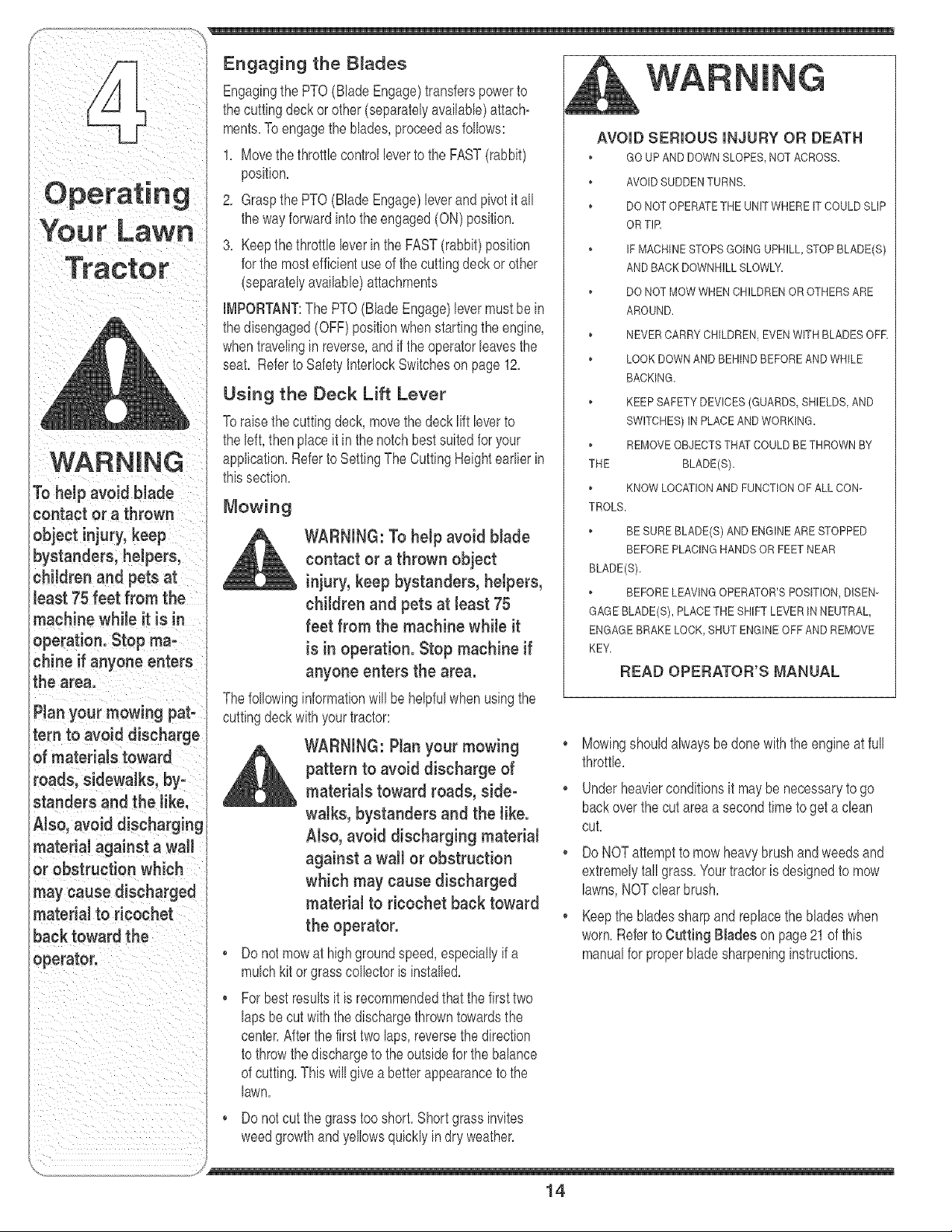
Engagingthe PTO(Blade Engage)transferspowerto
thecutting deckor other(separatelyavailable)attach-
ments.To engagethe blades,proceedas follows:
1. Movethe throttlecontrolleverto the FAST(rabbit)
position.
2. Graspthe PTO(BladeEngage)leverand pivotit all
the wayforwardinto theengaged(ON) position.
3. Keepthe throttleleverin the FAST(rabbit)position
for the mostefficientuseof the cuttingdeck or other
(separatelyavailable)attachments
IMPORTANT:The PTO(BladeEngage)levermustbein
thedisengaged(OFF)positionwhenstartingthe engine,
whentravelingin reverse,andif the operatorleavesthe
seat. Referto SafetyInterlockSwitcheson page12.
Using the Deck Lift Lever
Toraisethe cuttingdeck,movethe deck lift leverto
the left,then placeit in the notch bestsuited foryour
application.Referto SettingThe CuttingHeightearlier in
thissection.
Mowing
WARNING: To help avoid Made
contact or a thrown object
injury, keep bystanders, helpers,
children and pets at least 75
feet from the machine while it
is in operation. Stop machine if
anyone enters the area.
Thefollowinginformationwill be helpfulwhenusingthe
cuttingdeckwith yourtractor:
_ ARNING: Plan your mowing
pattern to avoid discharge of
materials toward roads, side°
walks, bystanders and the like.
Also, avoid discharging material
against a wall or obstruction
which may cause discharged
material to ricochet back toward
the operator.
• Do not mowat high groundspeed,especiallyif a
mulchkitorgrasscollectoris installed.
• For best resultsit is recommendedthatthe firsttwo
laps be cut with the dischargethrowntowardsthe
center.Afterthefirst two laps,reversethedirection
to throwthe dischargeto the outsidefor the balance
of cutting.This will givea better appearanceto the
lawn,
Do notcut the grasstoo short.Shortgrass invites
weedgrowthandyellowsquicklyin dry weather.
AVOID SERIOUS INJURY OR DEATH
, GO UPAND DOWN SLOPES,NOT ACROSS,
" AVOIDSUDDENTURNS,
" DO NOT OPERATETHE UNIT WHERE IT COULDSLIP
ORTIR
IFMACHINESTOPS GOINGUPHILL,STOP BLADE(S)
AND BACK DOWNHILLSLOWLY.
" DO NOT MOWWHEN CHILDRENOROTHERSARE
AROUND.
" NEVERCARRYCHILDREN,EVENWITH BLADESOFF.
" LOOK DOWNAND BEHINDBEFOREAND WHILE
BACKING.
" KEEP SAFETYDEVICES(GUARDS,SHIELDS,AND
SWITONES)INPLACE ANDWORKING.
" REMOVEOBJECTSTHATCOULDBE THROWNBY
THE BLADE(S).
o KNOW LOCATIONAND FUNCTIONOF ALL CON°
TROLB.
BE SURE BLADE(S)AND ENGINEARE STOPPED
BEFORE PLACINGHANDSORFEET NEAR
BLADE(S)_
" BEFORELEAVINGOPERATOR'SPOSITION,DISEN-
GAGE BLADE(S),PLACETHE SHIFT LEVERIN NEUTRAL,
ENGAGEBRAKELOCK,SHUT ENGINEOFF AND REMOVE
KEY,
READ OPERATOR'S MANUAL
Mowingshouldalwaysbedonewiththeengineat full
throttle.
Underheavierconditionsit maybenecessarytogo
backover thecut areaa secondtime to get a dean
cut.
Do NOTattemptto mow heavybrushand weedsand
extremelytall grass.Yourtractoris designedto mow
lawns,NOTclearbrush.
. Keepthe bladessharpand replacethe bladeswhen
worn.RefertoCutting Blades onpage21 of this
manualfor properbladesharpeninginstructions.
14
theyact as a naturalfertilizer,
Observethe followingpointsfor the best resultswhen
mulching:
, Neverattemptto mulchif the lawnis damp,Wet grass
tendsto stick to the undersideof the cuttingdeck
preventingpropermulchingof the clippings,
, Do NOTattemptto mulch morethan 1/3the total
heightof thegrass or approximately1-1/2inches,
Doingso will causethe clippingsto clumpup beneath
the deck and not be mulchedeffectively,
, Maintaina slowgroundspeedto allowthe grass
clippingsmoretimeto effectivelybe mulched,
Alwayspositionthe throttlecontrol leverin the FAST
(rabbit)positionandallowit to remaintherewhile
mowing,Failingto keepthe engineat full throttle
placesstrainon the tractor'sengineanddoes not
allowthe bladesto properlymulchgrass,
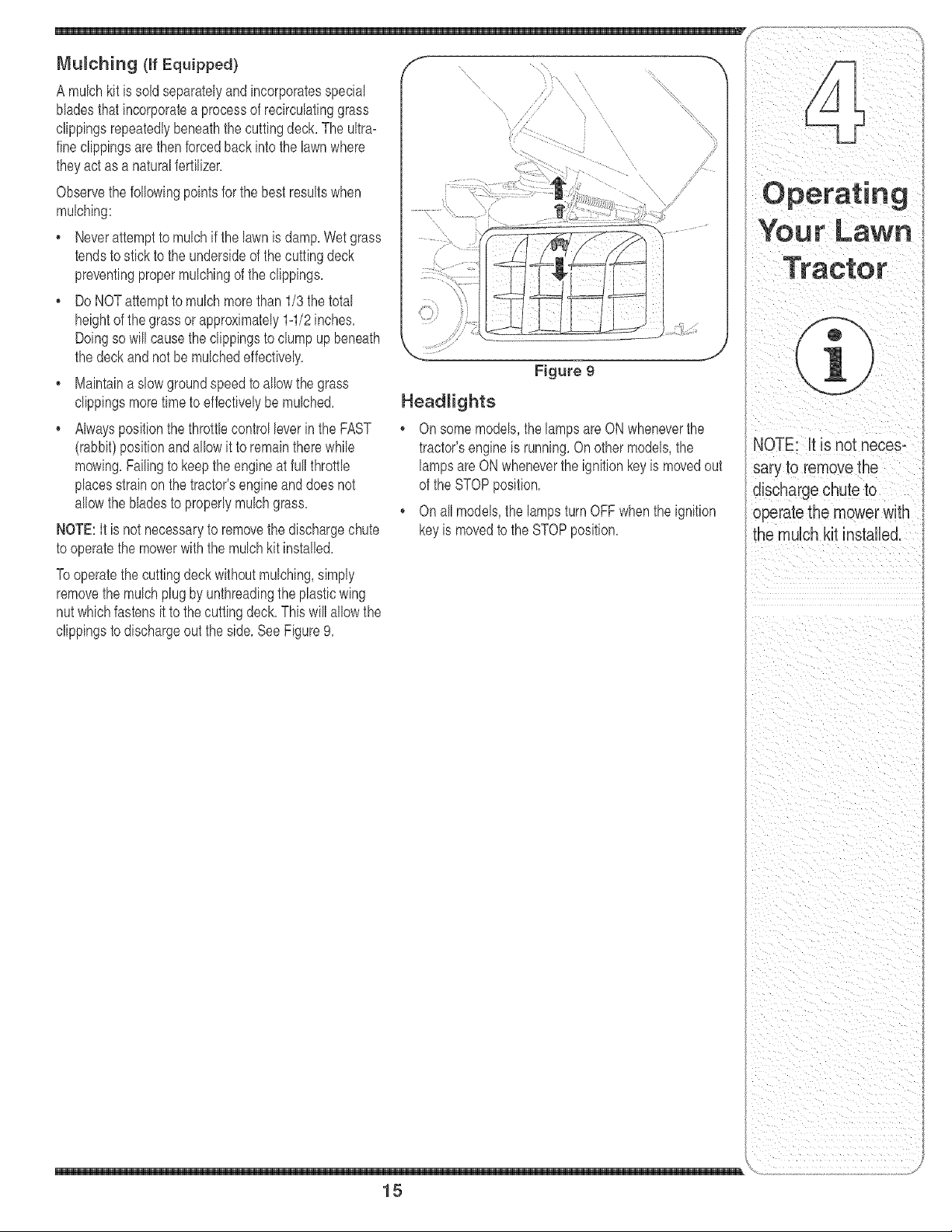
NOTE:It is not necessaryto removethe dischargechute
to operatethe mowerwith the mulchkit installed,
Tooperatethe cuttingdeck withoutmulching,simply
removethe mulchplugby unthreadingthe plasticwing
nut whichfastensit to thecuttingdeck,This will allowthe
clippingsto dischargeout the side,See Figure9,
Figure 9
Headlights
On somemodels,the lampsare ONwheneverthe
tractor'sengineis running,On othermodels,the
lampsareONwheneverthe ignitionkeyis movedout
of the STOPposition,
On allmodels,the lamps turnOFFwhenthe ignition
keyis movedto the STOPposition,
NOTE: It is not neces-
sary to removethe
discharge chuteto
operatethe mowerwith
the mulch kit installed.
15
!g
IrLaw
WARNING
Never attempt to
make any adjust=
meats whiJe the
engine is runninB,
except where speci-
fied in the operator's
manual
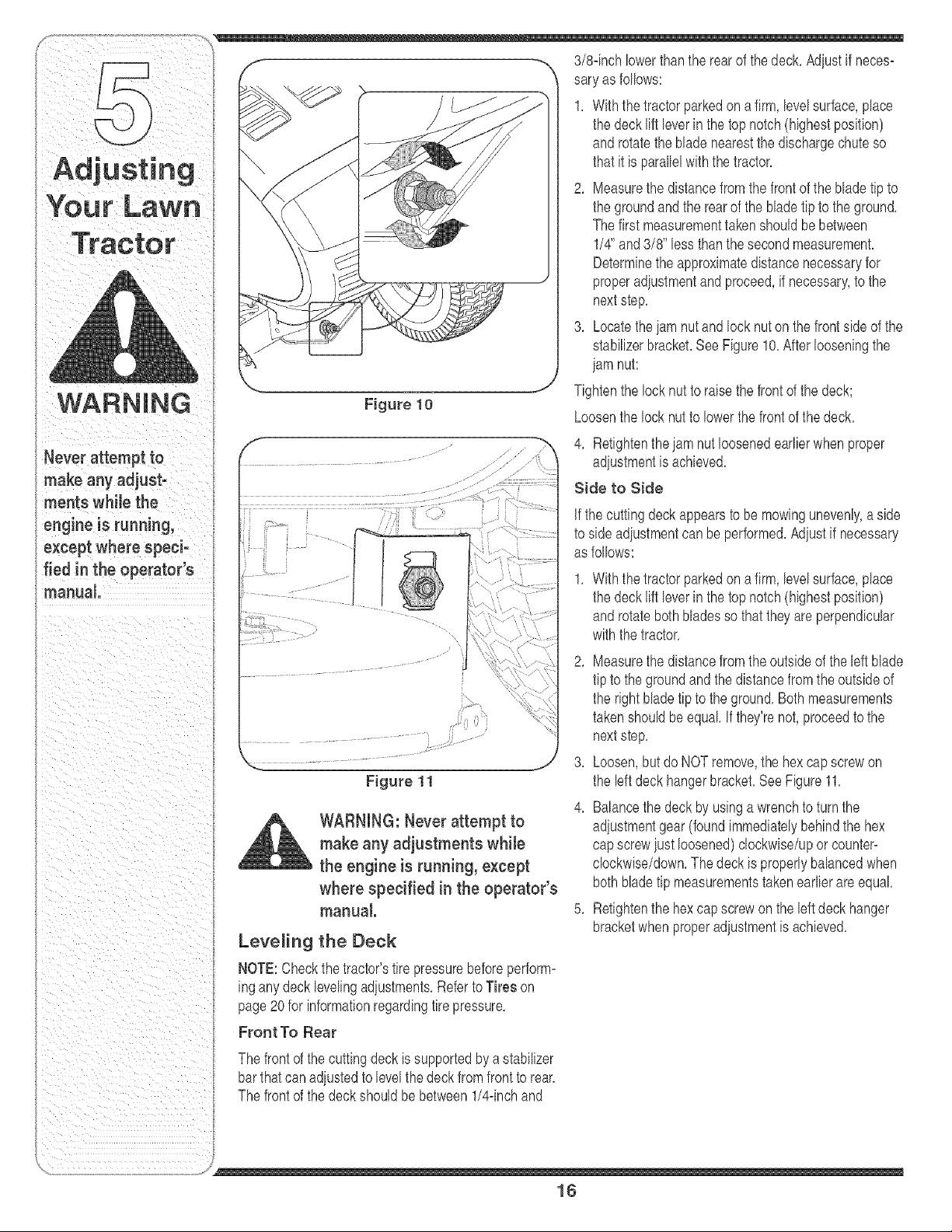
Figure 10
Figure 11
WARNING: Never attempt to
make any adjustments whiJe
the engine is running, except
where specified in the operator's
manual.
Leveling the Deck
NOTE:Checkthe tractor'stire pressurebeforeperform-
ingany deck levelingadiustments,Referto Tires on
page20 for informationregardingtire pressure,
Front To Rear
The front of the cuttingdeck is supportedbya stabilizer
barthatcan adiustedto levelthe deck from front to rear.
The front of the deck shouldbe between1/4dnchand
the deck lift leverin the top notch(highestposition)
androtatethe blade nearestthe dischargechute so
thatit is parallelwiththe tractor.
2. Measurethe distancefrom the front of the bladetip to
the groundand the rearof the bladetip to the ground.
Thefirst measurementtakenshouldbebetween
1/4" and3/8" lessthanthe secondmeasurement.
Determinethe approximatedistancenecessaryfor
properadiustmentandproceed,if necessary,to the
nextstep.
3. Locatetheiam nutand lock nut on the front sideof the
stabilizerbracket.SeeFigure10.Afterlooseningthe
iam nut:
Tightenthe lock nutto raisethe frontof the deck;
Loosenthe lock nut to lowerthe frontof the deck.
4. Retightenthe iam nut loosenedearlier whenproper
adiustmentis achieved.
Side to Side
Jfthecutting deckappearsto be mowingunevenly,a side
to sideadiustmentcan be performed.Adiustif necessary
as follows:
Withthetractor parkedon a firm,levelsurface,place
the deck lift leverin the top notch(highestposition)
androtate bothbladesso that they are perpendicular
withthe tractor.
2. Measurethe distancefrom the outsideof the left blade
tip to the groundand the distancefrom theoutsideof
the rightblade tipto the ground.Bothmeasurements
takenshouldbeequal If they'renot,proceedto the
nextstep.
3. Loosen,butdo NOTremove,the hexcap screwon
the left deck hangerbracket.See Figure11.
4. Balancethe deck by usinga wrenchto turnthe
adiustmentgear(foundimmediatelybehindthe hex
capscrewiust loosened)clockwise/uporcounter-
clockwise/down.Thedeckis properlybalancedwhen
both bladetip measurementstakenearlierareequal
5. Retightenthe hex capscrewon the left deck hanger
bracketwhenproperadiustmentis achieved.
16
moveshiftleverinto neutral posi-
tion, stop engine and remove key
to prevent unintended starting.
If the tractordoesnot cometo a completestop whenthe
brakepedalis completelydepressed,or if the tractor's
rearwheelscan roll with the parkingbrakeapplied,the
brakeis inneedof adjustment.Thebrakedisc can be
foundon the rightsideof the transmissionin the rearof
the tractor,Adjustif necessaryas follows:
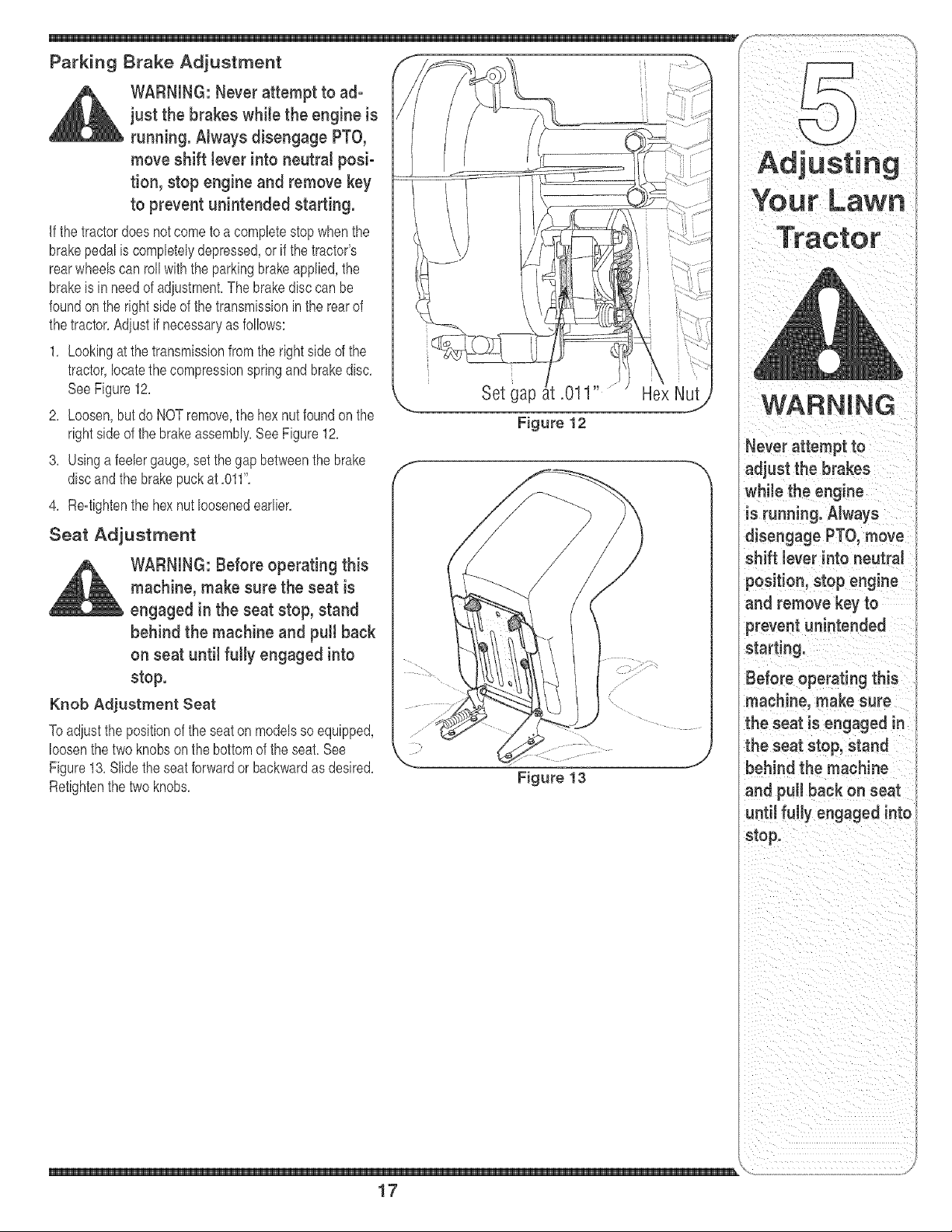
1, Lookingat thetransmissionfrom the rightside of the
tractor,locatethe compressionspringand brakedisc,
SeeFigure12,
2, Loosen,but do NOTremove,the hex nutfoundon the
rightsideof the brakeassembly,See Figure12,
3, Usinga feelergauge,setthe gap betweenthe brake
discandthe brakepuck at ,011",
4, Re=tightenthe hexnut loosenedearlier,
Seat Adjustment
WARNING: Before operating this
machine, make sure the seat is
engaged in the seat stop, stand
behind the machine and pu[[ back
on seat until fully engaged into
stop.
Knob Adjustment Seat
Toadjustthe positionof the seaton modelsso equipped,
loosenthe two knobs on the bottomof the seat, See
Figure13, Slidethe seat forwardor backwardas desired,
Retightenthe two knobs,
Set gap
Figure 13
Hex Nut
Never attempt to
adjust the brakes
while the engine
is running.Always
disengage PTO, move
shift lever into neutral
position, stop engine
and remove key to
prevent unintended
starting.
Before operating this
machine, make sure
the seat is engaged in
the seat stop, stand
behind the machine
and pu[[ back on seat
until fully engaged into
stop.
\
17
Maintaining
Your Lawn
Tractor
engine and remove key
to prevent unintended
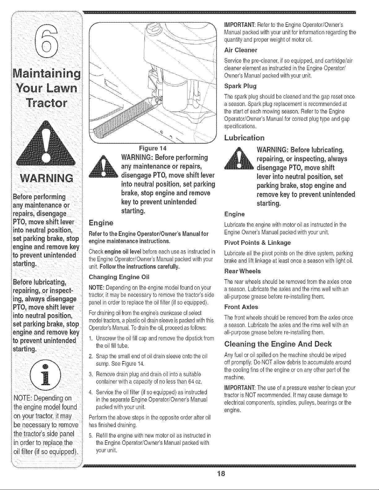
Figure 14
WARNING: Before performing
any maintenance or repairs,
disengage PTO, move shift lever
into neutral position, set parking
brake, stop engine and remove
key to prevent unintended
starting.
Engine
Referto the Engine OperatodOwneCsManual for
engine maintenance instructions.
Checkengine oil level beforeeachuseas instructedin
the EngineOperator/Owner'sManualpackedwithyour
unit,Follow the instructionscarefully.
Changing Engine Oil
NOTE:Dependingonthe engine modelfoundon your
tractor,it may be necessaryto removethe tractor'sside
panelin order to replacethe oil filter (if so equipped),
Fordrainingoilfromtheengine'scrankcaseofselect
modeltractors,aplasticoil drainsleeveis packedwiththis
Operator'sManualTodraintheoil,proceedasfollows:
1, Unscrewthe oil fill capand removethe dipstickfrom
the oil fill tube,
2, Snapthe small end of oil drain sleeveontothe oil
sump,SeeFigure14,
3, Removedrain plugand drain oil intoa suitable
containerwitha capacityof no lessthan 64 oz,
4, Servicethe oil filter (if soequipped)as instructed
inthe separateEngineOperator/Owner'sManual
packedwithyourunit,
Performthe abovestepsinthe oppositeorder afteroil
hasfinisheddraining,
5, Refillthe enginewith newmotoroil as instructedin
the EngineOperator/Owner'sManualpackedwith
IMPORTANT:Referto the EngineOperator/Owner's
Manualpackedwithyourunit for informationregardingthe
quantityand properweightof motoroil
Air Cteaner
Servicethe pre=cleaner,if so equipped,andcartridge/air
cleanerelementas instructedin the EngineOperator/
Owner'sManualpackedwithyour unit,
Spark PJug
Thesparkplugshouldbe cleanedand the gap reset once
a season,Sparkplugreplacementis recommendedat
the startof each mowingseason,Referto the Engine
Operator/Owner'sManualfor correctplugtype andgap
specifications,
Lubrication
_ ARNING: Before lubricating,
repairing, or inspecting,atways
disengage PTO, move shift
lever into neutrat position, set
parking brake, stop engine and
remove key to prevent unintended
starting.
Engine
Lubricatethe enginewithmotoroil as instructedin the
EngineOwner'sManualpackedwithyour unit,
Pivot Points & Linkage
Lubricateall the pivotpointson the drivesystem,parking
brakeandlift linkageat least oncea seasonwith lightoil
Rear Wheets
The rearwheelsshouldbe removedfrom the axles once
a season,Lubricatethe axles and the rimswell with an
all=purposegreasebeforere=installingthem,
Front AxJes
Thefrontwheelsshouldbe removedfrom the axles once
a season,Lubricatethe axles and the rimswell with an
all=purposegreasebeforere=installingthem,
C_eaning the Engine And Deck
Anyfuel or oil spilledonthe machineshouldbe wiped
off promptly,DoNOTallowdebristo accumulatearound
the coolingfins of the engine or on anyotherpart of the
machine,
IMPORTANT:The useof a pressurewasherto cleanyour
tractoris NOTrecommended,It maycausedamageto
electricalcomponents,spindles,pulleys,bearingsor the
engine,
18
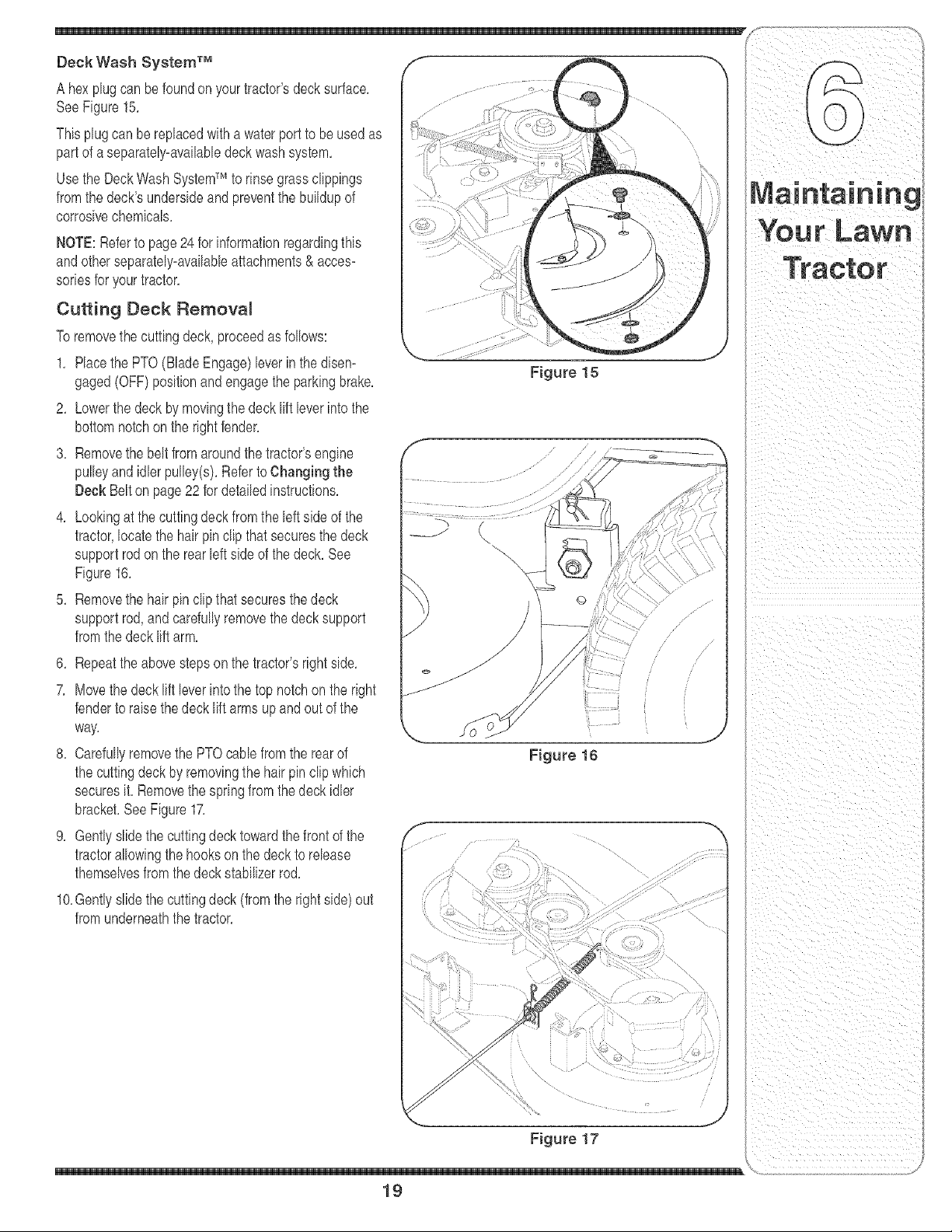
Deck Wash System TM
A hexplugcan be foundon yourtractor'sdecksurface,
SeeFigure15,
Thisplugcan be replacedwith a waterport to be used as
partof aseparately-availabledeckwashsystem,
Usethe DeckWashSystemTM to rinsegrassclippings
fromthedeck'sundersideandpreventthe buildupof
corrosivechemicals,
NOTE:Referto page 24 for informationregardingthis
andotherseparately-availableattachments& acces-
soriesfor yourtractor,
Cutting Deck Removal
Toremovethe cuttingdeck, proceedas follows:
1, Race the PTO(BladeEngage)leverin the disem
gaged(OFF)positionand engagethe parkingbrake,
2, Lowerthe deck by movingthedeck lift leverinto the
bottomnotchon the rightfender,
3, Removethe belt from aroundthe tractor'sengine
pulleyandidler pulley(s),RefertoChanging the
Deck Belton page22 for detailedinstructions,
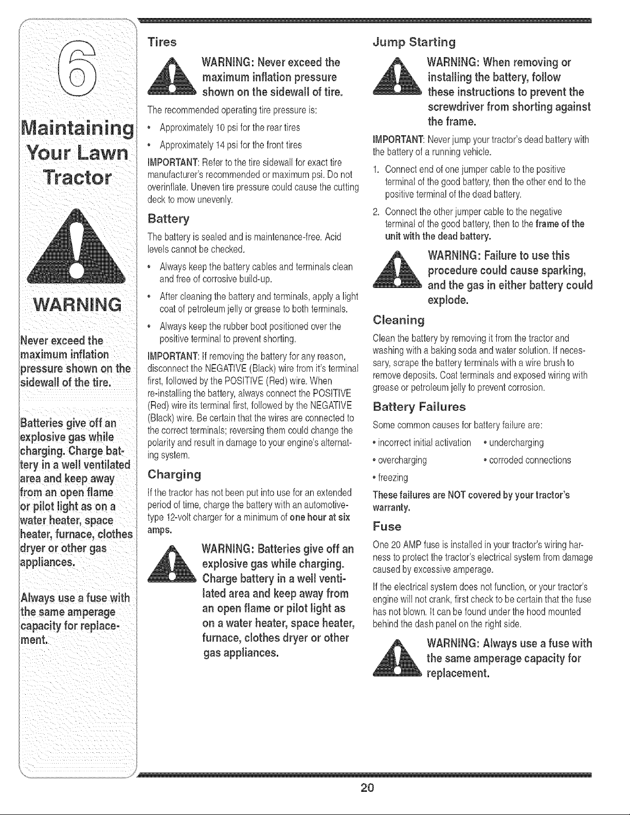
4, Lookingat the cuttingdeck fromthe left sideof the
tractor,locatethe hair pin dip that securesthe deck
supportrodon the rear left sideof thedeck, See
Figure16,
5, Removethe hair pin clipthat securesthedeck
supportrod, and carefullyremovethe deck support
fromthedeck liftarm,
6, Repeatthe abovestepson the tractor'srightside,
7, Movethe deck lift leverintothe top notchon the right
fenderto raisethedeck lift arms up and out of the
way,
8, Carefullyremovethe PTOcane from the rearof
the cuttingdeck by removingthe hair pin clipwhich
securesit, Removethe springfrom the deck idler
bracket,SeeFigure17,
9, Gentlyslidethe cuttingdeck towardthefront of the
tractorallowingthe hookson the deck to release
themselvesfromthedeck stabilizerrod,
10,Gentlyslidethe cuttingdeck (from the rightside)out
fromunderneaththetractor,
Figure 15
Figure 16
Figure 17
19
Tires Jump Starting
Neverexceed the
maximum inflation
_ressureshown on the
sidewall of the tire.
Batteries give off an
_xpiosive gas while
:harging. Charge bat-
tery in a we[[ ventilated
area and keep away
Froman open flame
or pilot light as on a
_ater heater, space
heater,furnace, clothes
dryer or other gas
_pp[iances.
Always use a fuse with
the same amperage
capacity for replace-
meat.
WARNING: Never exceed the
maximum inflation pressure
shown on the sidewall of tire.
The recommendedoperatingtire pressureis:
Approximately10psifor the rear tires
Approximately14psi for the fronttires
IMPORTANT:Referto the tire sidewallforexacttire
manufacturer'srecommendedormaximumpsi, Do not
overinflate,Uneventire pressurecouldcausethe cutting
deckto mow unevenly,
Battery
The batteryis sealedand is maintenance4ree,Acid
levelscannotbe checked,
Alwayskeepthe batterycanes and terminalsdean
andfreeof corrosivebuild-up,
Aftercleaningthe batteryand terminaB,apply a light
coatof petroleumicily or greasetoboth terminals,
Alwayskeepthe rubberbootpositionedoverthe
positiveterminalto preventshorting,
IMPORTANT:if removingthe batteryforany reason,
disconnectthe NEGATIVE(Black)wire from it's terminal
first,followedbythe POSITIVE(Red)wire,When
reqnstallingthe battery,alwaysconnectthe POSiTiVE
(Red)wire itsterminalfirst,fo[bwed bythe NEGATIVE
(Black)wire,Becertainthat thewiresare connectedto
thecorrectterminals;reversingthemcould changethe
polarityandresult in damageto your engine'salternat-
ingsystem,
Charging
If thetractor hasnot beenput into usefor an extended
periodof time,chargethe batterywith an automotive-
type 12-voltchargerfor a minimumof one hour at six
amps.
WARNING: Batteries give off an
explosive gas while charging.
Charge battery in a we[t venti-
lated area and keep away from
an open flame or pilot light as
on a water heater, space heater,
furnace, clothes dryer or other
gas appliances.
WARNING: When removing or
installingthe battery, follow
these instructions to prevent the
screwdriver from shorting against
the frame.
IMPORTANT:Neveriumpyourtractor'sdead batterywith
the batteryof a runningvehicle,
1, Connectend of one iumpercane to the positive
terminalof thegood battery,thenthe otherend to the
positiveterminalof the dead battery,
2, Connectthe otheriumpercane to the negative
terminalof thegood battery,thento the frame of the
unit with the dead battery.
WARNING: Failure to use this
procedure could cause sparking,
and the gas in either battery could
explode.
Cleaning
Cban the batteryby removingit fromthe tractorand
washingwitha bakingsodaandwatersolution,if neces-
saD',scrapethe batteryterminalswitha wire brushto
removedeposits,Coatterminalsandexposedwiringwith
greaseor petroleumicily to preventcorrosion,
Battery Failures
Somecommoncausesfor batteryfailureare:
incorrectinitialactivation • undercharging
overcharging _corrodedconnections
freezing
Thesefailures are NOTcovered by your tractor's
warranty.
Fuse
One20 AMPfuse is instalbd in yourtractor'swiringhap
hessto protectthe tractor'selectricalsystemfromdamage
causedby excessiveamperage,
if the ebctrical systemdoes notfunction,or your tractor's
enginewill not crank,first checkto be certain that the fuse
has notblown,It can be foundunderthe hoodmounted
behindthe dashpanelon the rightside,
WARNING: Always use a fuse with
the same amperage capacity for
replacement.
y
20
Cutting Blades
WARNING:Besuretoshut
theengineoff,removeignition
key, disconnect the spark plug
wke(s) and ground against the
engine to prevent unintended
starting before removing the cut-
ting Made(s) for sharpening or
replacement. Protect your hands
by using heavy gloves or a rag to
grasp the cutting Made.
WARNING: Periodically inspect
the Made spindles for cracks or
damage, especially if you strike a
foreign abject. Replace immedi-
ately if damaged.
Thebladesmaybe removedas follows,
1, Removethe deck from beneaththe tractor,(referto
CuttingDeckRemovalon page19)then gentlyflip
the deck overto exposeits underside,
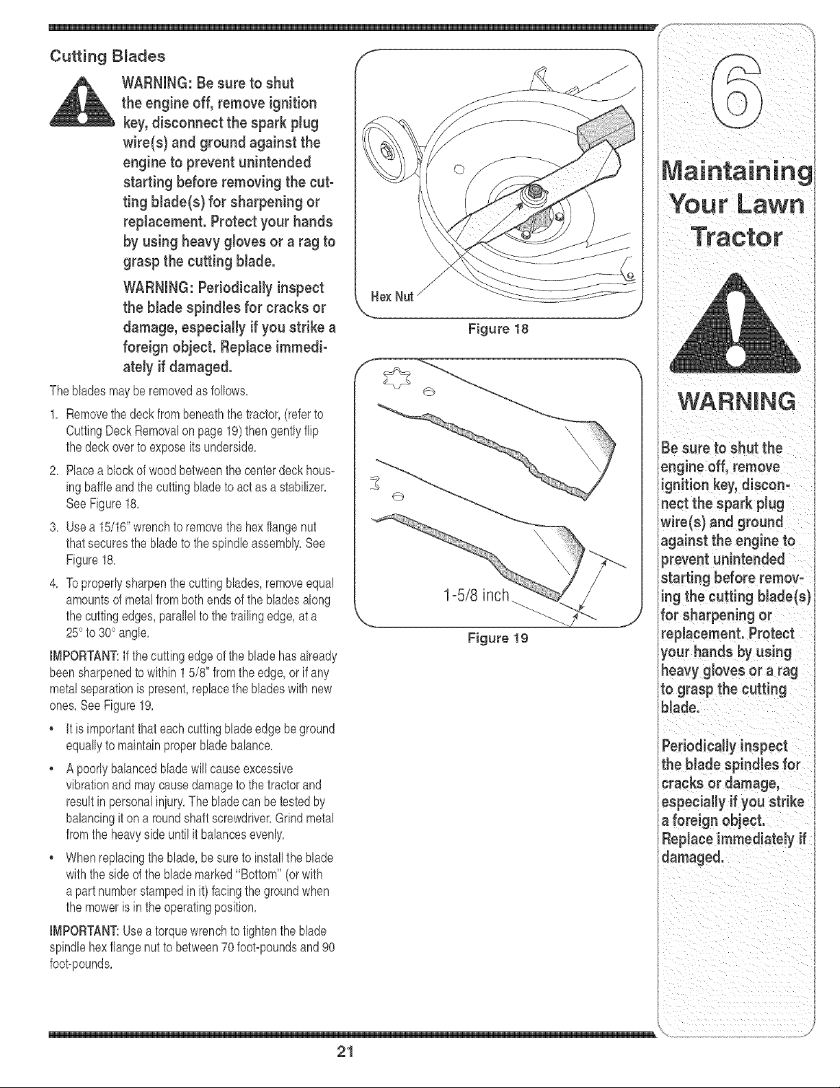
2, Race a blockof wood betweenthe centerdeck hous-
ingbaffle and the cuttingbladeto act asa stabilizer,
SeeFigure18,
3, Use a 15/16"wrenchto removethe hexflangenut
thatsecuresthe bladeto thespindleassembly,See
Figure18,
4, Toproperlysharpenthe cutting blades,removeequal
amountsof metalfrom bothends of the bladesalong
the cuttingedges, parallelto the trailingedge,at a
25° to 30° angle,
[[_tPORTANT:If the cuttingedgeof the blade hasalready
beensharpenedto within 1 5/8" fromthe edge,or if any
metalseparationis present,replacethe bladeswith new
ones,See Figure19,
• It is importantthat eachcuttingblade edge be ground
equallyto maintainproperbladebalance,
, A poorlybalancedbladewill causeexcessive
vibrationand maycausedamageto thetractorand
resultinpersonaliniury,The bladecan be testedby
balancingit on a roundshaftscrewdriver,Grindmetal
fromthe heavysideuntil it balancesevenly,
• Whenreplacingthe blade,be sureto installthe blade
withthe sideof the blade marked"Bottom" (orwith
a part numberstampedin it) facingthe groundwhen
the moweris in the operatingposition,
IMPORTANT:Usea torquewrenchto tightenthe blade
spindlehexflangenutto between70foot-poundsand 90
foot-pounds,
\
Figure 18
1-5/8 inch
Figure lg
-m
21
Be sure to shut the ,
engineoff,remove
ignition key, discon_
nect the spark Plug
wire(s} and ground
against the engine to
prevent unintended
Your Lawn
WARNING
Be sure to shut the
engine off, remove ig-
nition key, disconnect
the spark pJugwire(s)
and ground against
the engine to prevent
unintended starting
before removing the
beJt(s).
Avoid the possibility of
a pinching injury. Do
not place your fingers
an the idler spring or
between the belt and a
pulleywhile removing
the belt.
3/8" uareHole1
Figure 20
Changing the Deck Belt
WARNING: Be sure to shut
the engine off, remove ignition
key, disconnect the spark plug
wke(s) and ground against the
engine to prevent unintended
starting before removing the
belt(s).
The belton your tractoris subieetto wearand shouldbe
replacedif any signsof wearare present,
IMPORTANT:The V-beltfoundon yourtractorare
speciallydesignedto engageand disengagesafely,A
substitute(nomOEM)V-beltcan bedangerousby not
disengagingcompletely,Fora properworkingmachine,
usea factoryapprovedbelt,
Tochangeorreplacethe deck belt proceedas follows:
1, Lowerthe deck by movingthedeck lift leverintothe
bottomnotchonthe right fender,
2, Removethe beltguardsby removingtheself-tapping
screwsthatfastenthem to the deck,
3, Removethebelt keeperrod fromaroundthe engine
pulley,
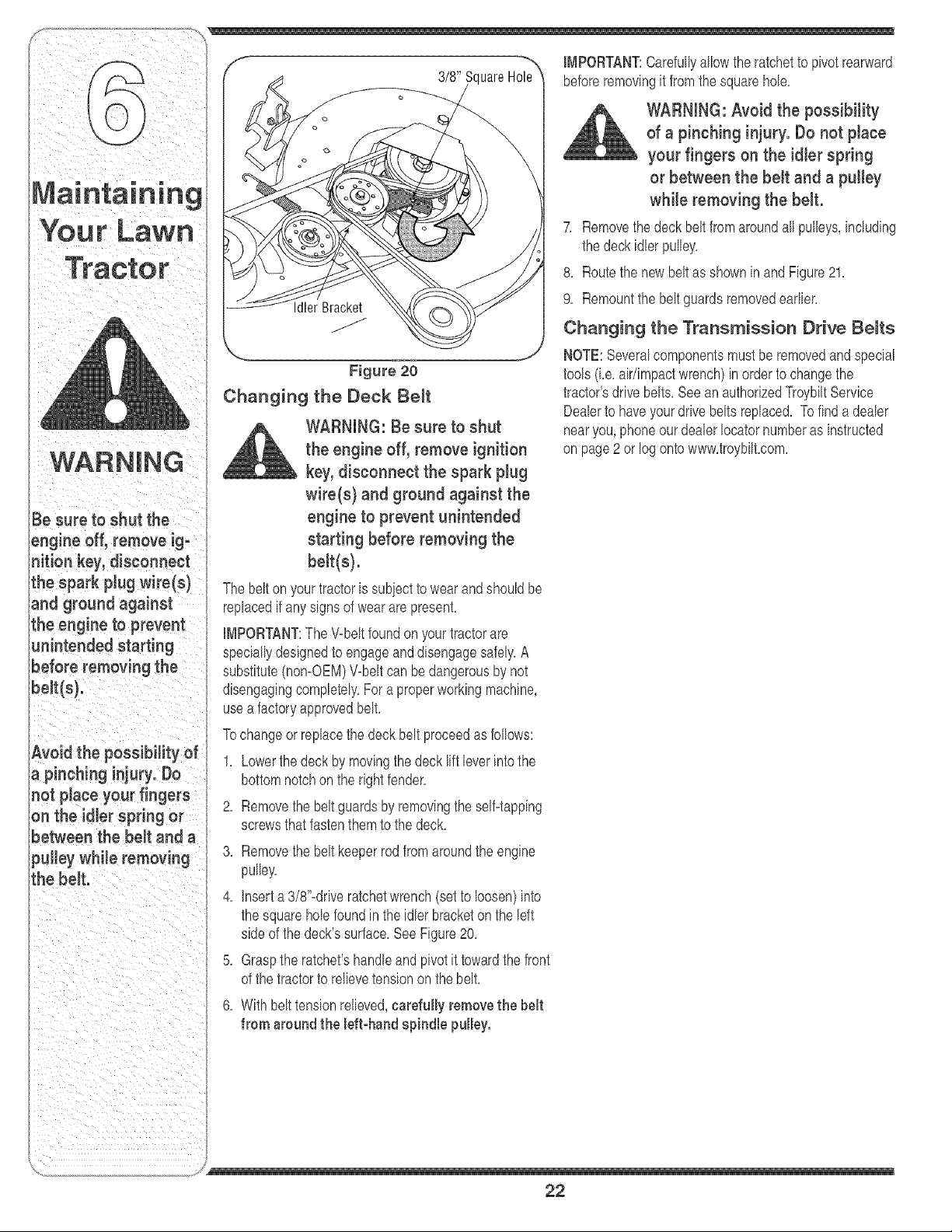
4, insert a 3/8"-driveratchetwrench (set to loosen)into
the squarehole foundin the idler bracketon the left
sideof thedeck'ssurface,SeeFigure20,
5, Graspthe ratchet'shandleand pivot it towardthe front
of the tractorto relievetensionon the belt,
6, With belttensionrelieved,carefully removethe belt
from around the left-hand spindle pulley.
IMPORTANT:Carefullyallowthe ratchetto pivotrearward
beforeremovingit fromthe squarehole,
WARNING: Avoid the possibility
of a pinching injury. Do not place
your fingers on the idler spring
or between the belt and a pulley
while removing the belt.
7, Removethe deck belt fromaroundall pulleys,including
the deck idler pulley,
8, Routethe newbelt as shownin and Figure21,
9, Remountthe beltguardsremovedearlier,
Changing the Transmission Drive Belts
NOTE:Severalcomponentsmust beremovedandspecial
tools(ke, air/impactwrench)in orderto changethe
tractor'sdrbfebelts,SeeanauthorizedTroybiltService
Dealerto haveyour drivebeltsreplaced, Tofind a dealer
nearyou,phoneour dealerIocatornumberas instructed
on page2 orlog ontowww,troybilt,com,
J
22
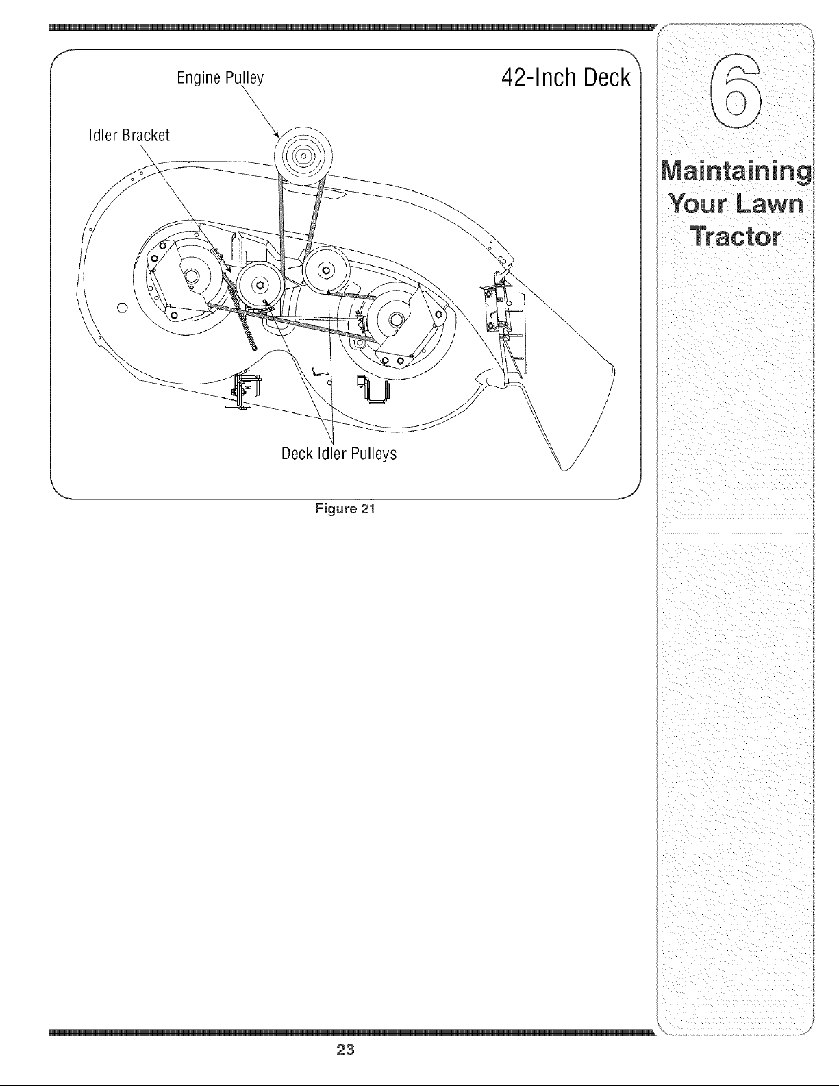
IdlerBracket
EnginePu_
DeckIdlerPulleys
Figure 21
_J
23

, Cleanandlubricatethe tractoras instructedin Section Followthe instructionsin the Service Storage &
J 6' MAINTAININGYOURLAWNTRACTORon page18 Specifications sectionof the EngineOperator/Owners
of this manualbeforestoringfor an extendedperiod, Manualfor properenginecare prior to storingyourtractor,
WARNING: Drain fueJonly into
an approved container outdoors,
away from an open flame. Allow
engine to coot. Extinguish
cigarettes, cigars, pipes, and
other sources of ignition prior to
draining fuel.
WARNING: Never store the
machine or fuel container indoors
where there is an open flame,
spark or piJot Jight such as on
water heater, furnace, clothes
dryer or other gas appliance.
WARNING
Drain fuel only into an
approved container
outdoors, away from
an open flame. N-
low engine to cool.
Extinguish cigarettes,
cigars, pipes, and
other sources of igni-
tion prior to draining
fuel.
Never store the ma-
chine or fuel container
indoors where there is
an open flame, spark
or pilot light such
as on water heater,
furnace, clothes dryer
or other gas appliance.
Attachments & Accessories
The followingattachmentsand accessoriesare compatiblefor ModelSeries700 LawnTractors,See the retailerfrom
whichyou purchasedyourtractor,an authorizedTroybiltServiceDealeror phone(866) 840=6483for information
regardingpriceandavailability,
NOTE:ModelSeries700 LawnTractorsare NOTdesignedfor usewithany typeof ground-engagingattachments
(e,g,tiller or plow),Use of this type of equipmentWILL voidthe tractor'swarranty,
MODEL DESCRIPTION
0EM-190-032
0EM-!90-116
0EM-190-180
0EM-190-183
0EM-190-218
0EM-190-607"
0EM-190-658
0EM-190-672
0EM-190-833
490-900-0025
42-inchTwo-stageSnowThrower
38/42-inchDeckMulchKit
TwinBaggerGrassCollector(for38/42-inchDecks)
DeckWheel Kit
RearWheelWeightKit
DeluxeTractorSunshade
Tire Chains,20 x 8Tires
GrilleGuard(mountsonfrontoftractor)
42-inchFrontDozerBlade
DeckWashKit
Notcompatiblewithtractorsequippedwitha GrassCollector
24
_andinstructions
25

For repairs beyond
the minor adjust-
ments listed here,
contact an authorized
service dealer.
Problem
Engine runs erratic
Cause
1, Unit runningwith CHOKEapplied,
2, Sparkplug wire(s) loose,
3, Blockedfuel lineor stab fuel
4, Ventin gas cap plugged,
5, Wateror dirt in fuel system,
6, Dirty air cbaner,
Remedy
1, PushCHOKEcontrol(if so
equipped)in, or movethe throttle
controlout of the CHOKEposition,
2, Connectand tightenspark
plugwire(s),
3, Cban fuel line;fill tank with clean,
fresh(less than30 daysold)
gasoline,Replacefuel filter,if so
equipped,
4, Char vent or replaceif damaged,
5, Drainfuel tank, Refillwith
freshfuel
6, Replaceaircleanercartridge/eb-
mentor cleanpre-cleaner,if so
equipped,
26

Problem Cause
2, Airflow restricted, 2, Cban grassclippingsar!ddebris
from aroundthe engines CooLing
f ns and b owerhousng,
Engine hesitates at 1, Sparkplug(s)gap tooclose, 1, Removesparkplug(s)and reset
high RPM thegap,
' ' equipped,
Excessive
Vibration
Uneven cut
1, Cuttingblade looseor unbalanced,
2, Damagedor bentcutting blade,
1, Decknot balancedproperly,
2, Dullblade,
3, Uneventire pressure,
1, Tightenbladeand spindle,Balanc(
blade,
2, Replaceblade,
1, Performside-to-sidedeck adiust-
ment,
2, Sharpenor replaceblade,
3, Checktire pressurein all fourtires,
For repairs beyond
the minor adjust-
ments listed here,
contact an authorized
service dealer,
27
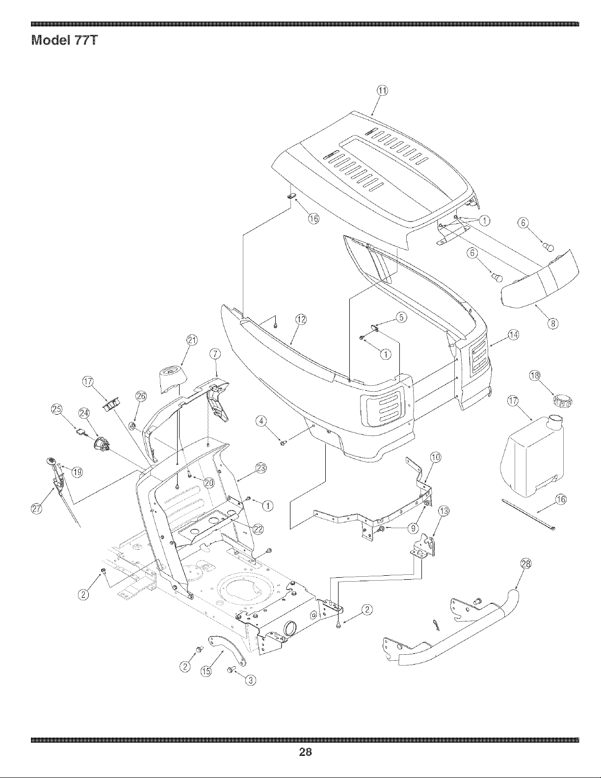
Mode_ 77T
?
\\\\
@
\\\\
©
\\\
28

710-0599
710-0604A
710-1260A
710-1611B
712-0185
725-0963
731-05078A
731-15357
738-04091
783-04606A
783-04827
783-04828
783-04841
783-04840
783-04967
Screw,1/4-20,0,500
Screw,5/16-18,0,625
Screw,5/16-18,0,750
Screw,5/16-18,0,750
Nut, 1/4-20,SpeedU-type
Headlamp,12V
Collar,Dash,3-Style
Troy-BiltLens
Screw,Shldr,,43x ,29,5/16-18
PivotBracket
Troy-BiltHood
Troy-BiltSidePanel,RH
HoodPivotBracket,LH
HoodPivotBracket,RH
Troy-BiltSidePanel,LH
783-05027
726-0230
751-0555B
751-0603
710-04483
710-0895
731-04945
783-04584
783-04873
725q741
725-1744
731-05265
746-04258
725-04361
190-672"
FrontPivotSupportBracket
CableTie,34,75
FuelTank,1,5gaL
FuelTankCap
Screw,1/4-14,,500
Screw,1/4-15,,750
Support,Steering
GasTankSupportBracket
DashAssembly
Module,ignitionSwitch
Key
ChokePlug
Throttle/ChokeControl,25,0
Wire Harness(No RMC)
BumperKit
*ModelsSo Equipped
For parts and/or
accessories
please call
t-866-840-6483, or
1-330-558-7220.
www.troybilt.com
\
29
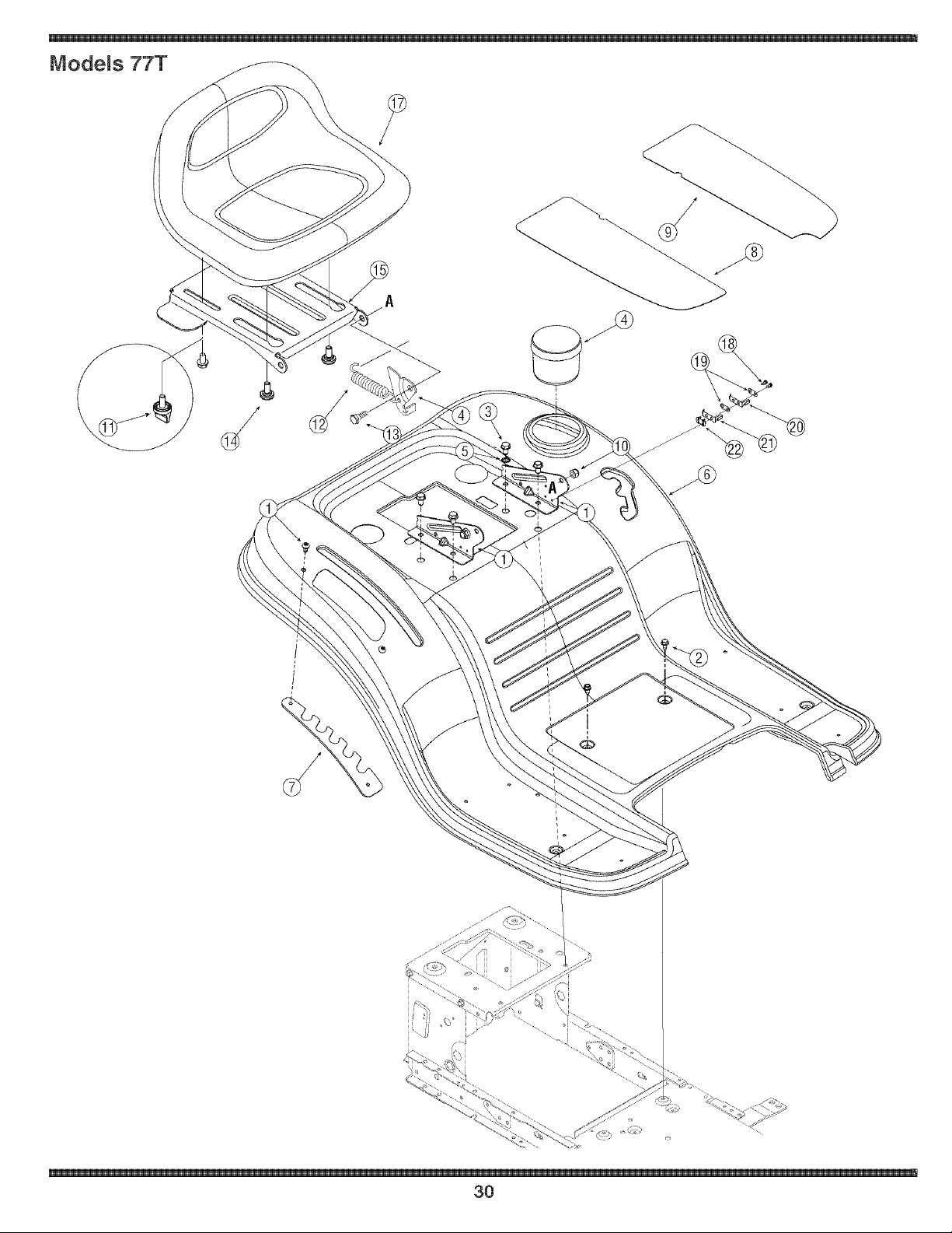
Mode_s 77T
?
I
r ,, ,
3O

710-04483 Screw,1/4-20x .500
2 710-0599 Screw,1/4-20,0.500
3 710_0604A Screw,5/16-18,0.625
4 731-04591A Cup Holder
5 736_0607 LockWasher,5/16
6 783-04587A Fender
7 783q489B MountingBracket,Seat
8 723_04025 FootPad,Abrasive,RH
9 723_04026 FootPad,Abrasive,LH
10 712_04063 Nut, FlangeLock,5/16-18,GrF
11 720-04061 Knob,3/8q6, .875
12 732q184 Spring,Exten.,.84 Diax 4.6 Lg.
13 738-0296 Scr, Shlder,.437x.288, 5/16-18
14 738-04012A Screw,Shlder,.625x.175, 3/8q6
15 783_04081A PivotBracket,Seat
16 783-0209D Lift Bracket,Seat
17 757-04021A Seat,Low,Black
18 710-0227 Screw,#8q8x.50
19 726-0279 Plate,Insulator
20 725q303 SpringSwitch,Outer
21 725q439 SpringSwitch,inner
22 726-0278 Plate,InsulatorBoss
For parts andlor
accessories
please call
1-866-840-6483,or
1-330-558-7220.
v_tw.troybilt.com
\
31
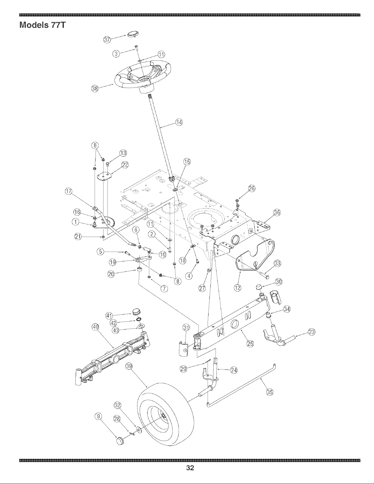
Mode_s 77T
@
\
\
32

1 617-04024
2 710-0376
3 710-0643
4 710q309
5 710-3180
6 71b0240
7 71b0262
8 71b04063
9 731-0484A
10 723-0448A
11 736-0242
12 783-04568
13 738-04141
14 738-0919
15 741-04124
16 741_0475
17 74_04298
18 748_0389
19 748-04065
20 748-04068
21 750-04418
22 783-04644
23 638_04007
GearAssembly,Steering 24 638-04008
Screw,5/16q8, 1.00,Gr5 25 683-0128B
Screw,5/16=18,1.00,Gr5, Lock 26 710-0726
Screw,Mach,5/16=18,0.750 27 71b04065
Screw,5/16q8, 1.75,@5 28 714-04039
Nut,Jam,7/16_20,@2 29 714_0470
Nut,JamLock,3/8-24,Gr2 30 726-0341
Nut,FlangeLock,5/16q8,Grf 31 731-04057A
HubCap 32 736_0316
BaliJoint, 7/16_20,Lock 33 738_04128
Washer,Bell, .340x .872x .060 34 741-0660A
FrontHangerBracket,Deck 35 747_04299A
Scr. Shlder,.435 x .3485,5/16=18 36 783-04601B
SteeringShaft,5/8 Splinex 21.86 37 731-04681
Bearing,Flange,Hex5/8 38 631_04028
PlasticBushing.380ID 39 634-04086
DragLink,Steering 734=1731
Cap,1.25x .16 634-04081
Steering,Block 40 719_04105
Spacer,.710ID x .125OD x .56 41 731-04693
Spacer,.322 JDx .625OD x .21 42 726-04035
StabilizerPlate,GearSegment 43 736_0316
Axle Assembly,LH
Axle Assembly,RH
PivotBar
Screw,5/16=12,0.750
Nut, FlangeLock,3/8=16,GrF
Pin,Cotter,5/32, 1.25
Pin,Cotter,1/8x 1.25
PushCap,3/4
EndCap,Pivot Bar (w/ Fitting)
Washer,Flat, .78x 1.59x .060
Scr.,Shlder,.500x 2.380,3/8=16
Bearing,Flange,.760x .941x 1.0
Tie Rod
Bracket,Pivot
Cap,SteeringWheel(tine logo)
SteeringWheel,StandardGrip
WheelAss'y,SquareShoulder
TireOnly,15x 6x 6, SquareShld.
RimAssembly(ind.bearings&stem)
PivotBar,Cast Iron
PushCap
PushNut,3/4"
FlatWasher,.78x 1.59x .060
For parts and/or
accessories
please call
to866o840o6483,or
1-330-558-7220.
wv_v.troybiJt.com
\
33
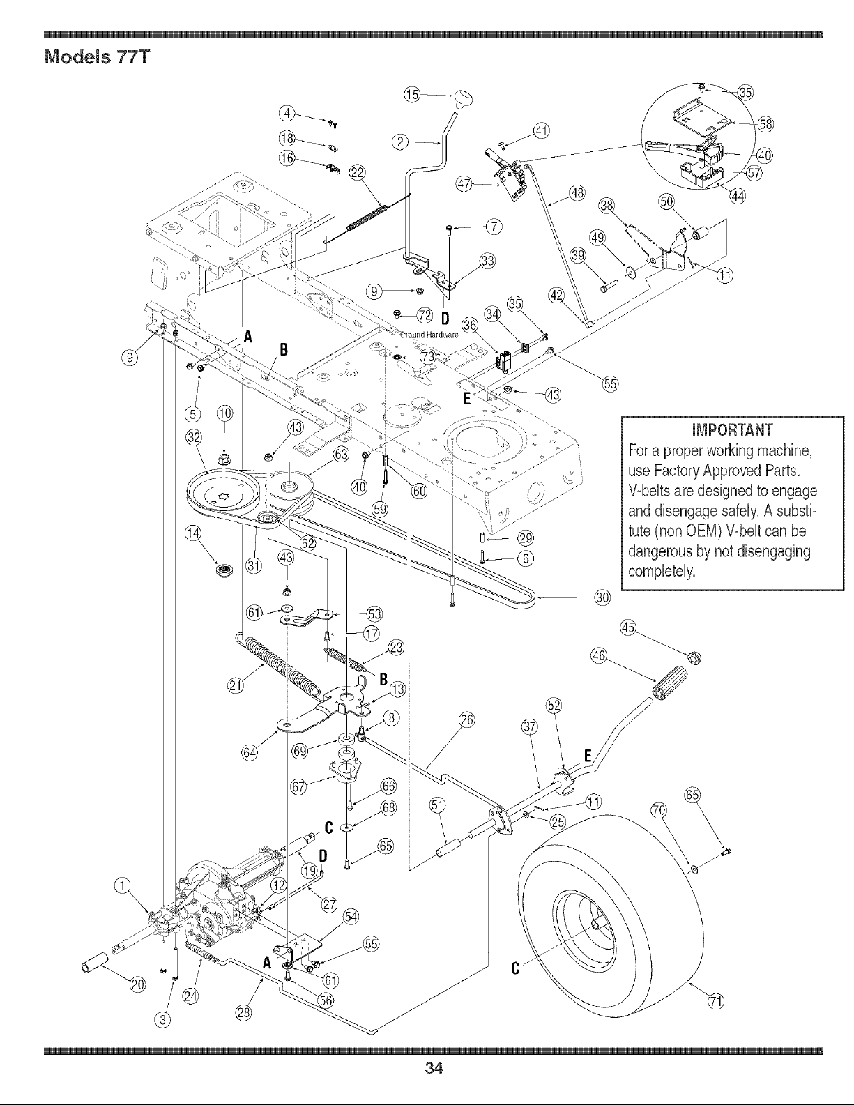
Mode_s 77T
A B
@
IMPORTANT
Fora proper working machine,
use FactoryApproved Parts.
Wbeits are designed to engage
and disengage safely.A subsfi-
tute (non OEM) Wbeit can be
dangerous by not disengaging
completely.
®
34

J_
1 618_04034 TransmissionAssembly
2 647_04035 LeverAssembly,Shift
3 710-0176 Screw,5/16q8, 2,75, Gr5
4 710-0227 Screw,#8q8, 0,500
5 710-0726 Screw,5/16q2, 0,750
6 710-0809 Screw,1/4-20,1,250
7 710-3008 Screw,5/16q8, ,75,@5
8 711-04075A Ferrule,3/8-24x,375 Dia,
9 71b04063 Nut,FlangeLock,5/16q8,G
10 71b0700 Nut,Flange,9/16q8, Gr2
11 714_0111 Pin,Cotter,3/32, 1,0
12 714-0209 CotterPin, Internal,125Dia
13 714-0470 Pin,Cotter,1/8 x 1,25
14 718-0758A Hub,Pulley,5/8 Spline
15 720_04028 Knob,Shift
16 7254644 SpringSwitch,Short
17 710-0520 Screw,3/8q6 x 1,50
18 726_0320 Plate, insulatorNut
19 731-04602 I Sleeve,,758x,821 x 3,3125
20 731-04604 Sleeve,,758x ,821x 2,4375
21 73bO4076A Spring,Extension,1,150D x
22 73b04237 Spring,Extension,,50 OD x 12,0
23 73b04306 Spring,Extension,,80 OD x 3,28
24 73b0716C Spring,Extension,,59 OD x 4,00
25 736-0264 Washer,Flat,,330 x ,630 x ,/
26 747-04265 ContolRod,VariableS)eed
27 747_04277 Rod,Shift
28 747_04287 Rod,Brake
29 750-0566A Spacer,,260x ,372x 1,030
30 754_04001A Belt
31 754-0241A Belt
32 756_04002 Pulley,WType,7,25Dia
33 783-04595 ShiftBracket,Adiustable
34 17962 Plate,Switch
35 710-0224 Screw,#10q6, 0,500
36 725_04039 Switch,interlock
37 647-04034C PedalAssembly,Drive
38 783_04903 LatchBracket(No RMC)
39 7104008 Screw,3/8-16, 1,875,@5
40 731-05362 7Speed ShiftLever
41 710-04483 Screw,1/4-20,0,500
42 711-0736 AdiustmentFerrule1/4-20
43 71b04065 Nut, FlangeLock,3/8q6, Gr
44 731-05361 ControlCover
45 726-0214 PushCap,5/8
46 735-0239 Pad,Foot,4,0
47 683_04216 ShiftCont, Assembly,7_Spe_
48 747_04430 ControlRod, SpeedSelector
49 736-0247 Washer,Flat,,406x 1,25x ,157
50 750-04465 Spacer,Fig& ,390x ,671x 1,095
51 750-0802 Spacer,,640JDx ,76OD x 2,63
52 783_04536 SupportBracket,Pedal
53 683-04207 Bracket,Idler
54 683-04176A TorqueBracket,Transmissio
55 710-0604A Screw,5/16q8,0,625
56 710-0520 Screw,3/8q6, 1,50,Gr5
57 73b0627 Shift LeverSpring
58 783_04830 ControlBracket
59 710q325 Screw,1/4-20x 1,625
60 750-04456 Spacer,,260x ,372x 1,420
61 738-0347 Spacer,Shoulder,,625JDx ,169
62 756-04213 Pulley,FlatIdler
63 656-04015 PulleyAss'y,VariableS_eed
64 683_04206 BracketAss'y,VariableSpee
65 710-0627 Screw,5/16-24,,750,Gr5
66 710q652 Screw,1/4-20,0,625
67 718-04012 Cup,Bearing
68 736-0362 Washer,Flat,,330x 1,25x ,(
69 741_0600 Bearing,Ball, 17x 40 x 12
70 736-0242 Bell Washer,,34 x ,872 x ,0
71 634-0104 WheelAss'y,SquareShould,
7344730 TireOnly,20 x 8 x 8, S¢uare Shld
734_0603A Rim Assemblytint,bearings&,
72 710-0599 Screw,1/4-20x ,500
73 736-0222 LockWasher,1/4
For parts and/or
accessories
please carl
1-866-840-6483,or
to330o558o7220.
www.troybiJt.com
\
35
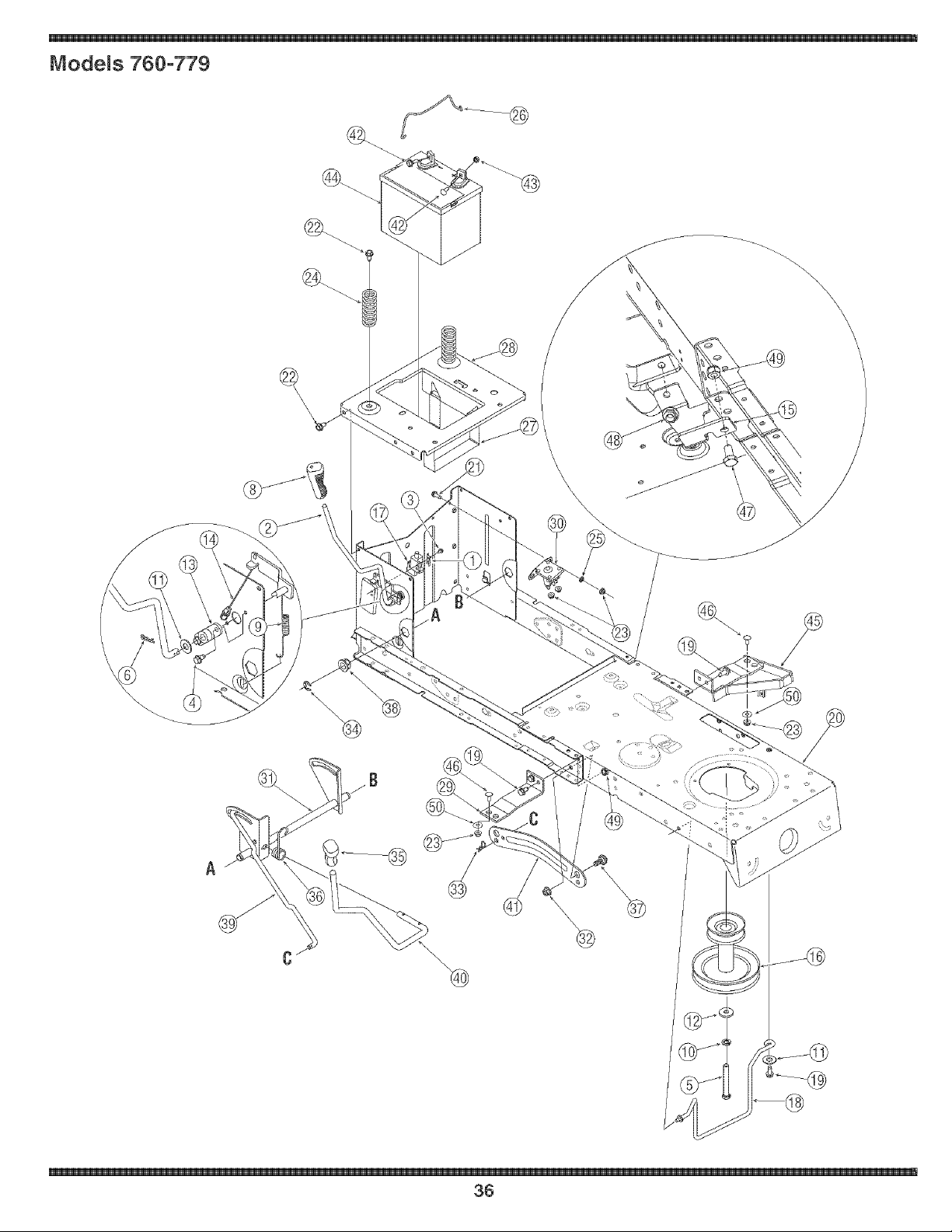
Mode_s 760-779
\
\
\
36

17962
647-04040
710-0224
710-0599
710-3157
714-0104
714-0145
720-04049
732-04276
736-0171
736-0300
738-0322
741-04119
746-04173A
783-04753
756-04196
725-04039
747-04307
710-1260A
683-04163A
710-0842
710-0604A
712-04064
732-04035
736-0222
747-04385
783-04869
Plate,Switch
HandleAsswmbly,PTO
Screw,#10-16,0.500
Screw,1/4-20,0.500
Screw,7/16-20,3.25,Gr5
Pin,Cotter,.072Dia.x 1.13
Pin,Click,.092x 1.64
Grip,Handle,3/8
Spring,Extension
Washer,Lock, 7/16
Washer,Flat,.406x .875x .059
Washer,Flat,.450x 1.250x .184
Bearing,PTO
Cable,DeckEngagement
FrameSupportBracket
EnginePulley,3.39 x 6.12Dia.
Switch,Interlock
Rod,Belt Keeper(42dnchDeck)
Screw,5/16-18,.750
FrameAssembly
Screw,1/4-20,0.750
Screw,5/16-18,0.625
Nut, FlangeLock, 1/4-20,GrF
Spring,Compr., 1.28ODx 3.125
Washer,Lock,1/4
Hold DownRod,Battery
Bracket,Battery
783-04548A
783-04637
725-1426A
883-04155
712-04065
714-04043
716-0106A
720-0311
732-04225
738-04130
741-0225
74_04393
74_04282
783-04494
783-04711
710-0703
712-0271
725-1737A
683-04195
710-0134
710-3025
712-04063
712-0429
736-0173
SeatBracket,Frame
Bracket,RuningBoard
Solenoid
ShaftAssembly,Lift
Nut,FlangeLock,3/8-16,GrF
Pin,Cotter,.080x 1.5625internal
Ring,E-Type,.625Dia.
Grip, Handle,1/2
Spring,Torsion
Screw,Shldr., .625x .175,3/8-16
Bearing,HexFlange
Rod,Lift
DeckHandle,Lift
LiftArm, Deck- RH
LiftArm, Deck- LH
Screw,Carriage,1/4-20,.75,Gr5
Nut,Sems,1/4-20
Battery,190CCA
SupportBracketAssembly
CarriageScrew,1/4-20x .62
Screw,5/16-18x .625
FlangeLockNut,5/16-18
HexLockNut,5/16-18
FlatWasher,.28 x .74x .063
....
For parts andlor
accessories
please call
1-866-840-6483,or
1-330-558-7220.
v_t_.troybilt.com
\
37
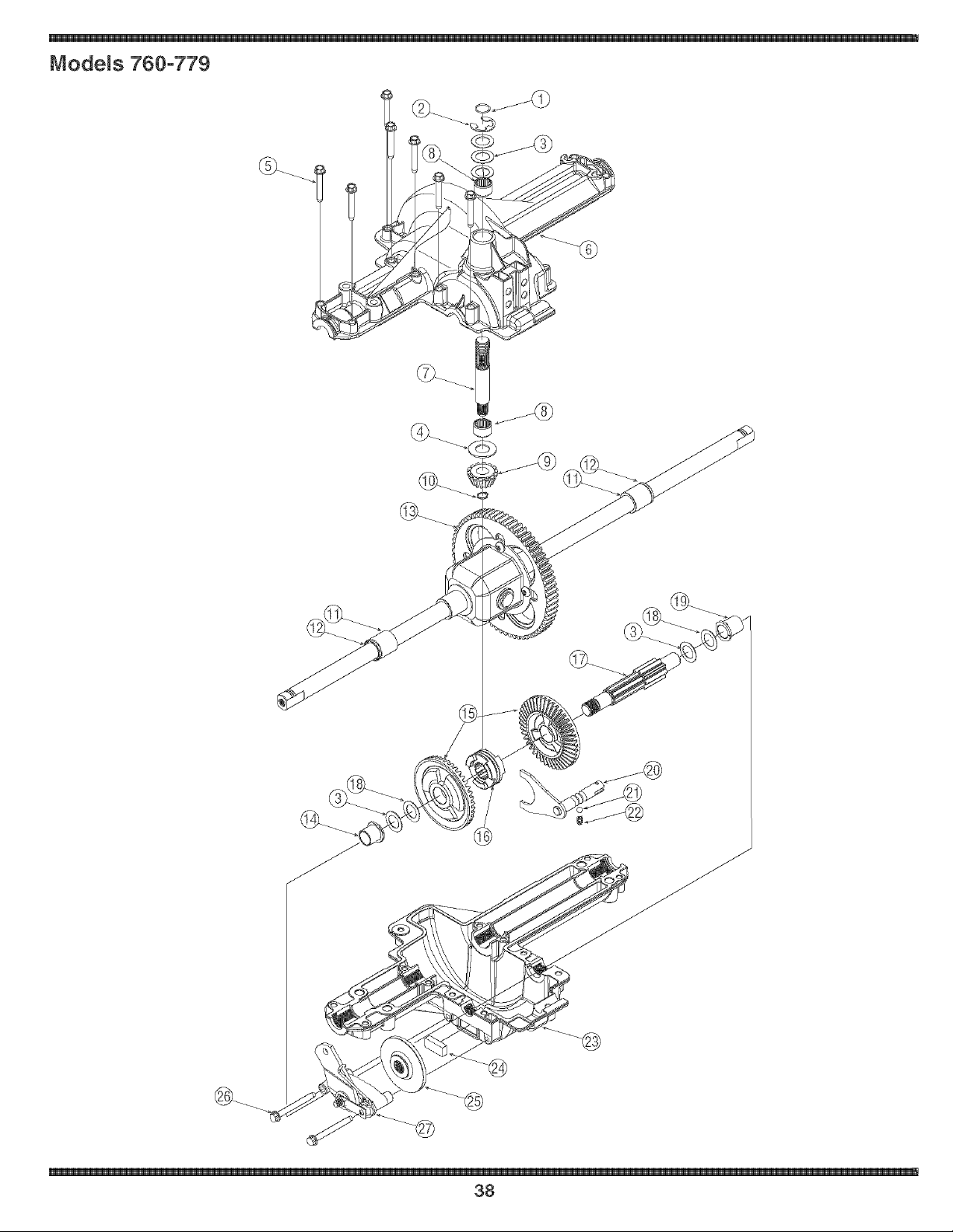
Mode_s 760-779
38

732-0614
716-0231
736-0336"
736-0337"
736-0349"
736_0335
710-1325
719-04017
711-1109
741-0335
717-1464
716-0108
741-0340
721_0338
618-04041
741_0336
717-04056
718-04045
711-04134
736-0495"
736-0494"
741-0337
611-0011
741_0862
732_0863
719-04018
717-0678
761-0202
710-1206
661-0001
737-0148
Ring,Wire
Ring,E Type.750
FlatWasher,5/8 x 1.0x.030
FlatWasher,5/8 x 1.0x.040
FlatWasher,5/8 x 1.0x.020
Washer,Thrust.635x 1.26x.06
Self-tappingScrew,1/4-20x 1.625
UpperHousing
input Shaft
NeedleBearing,.625x.813x.495
14-toothBevelPinion
RetainingRing.437
SleeveBearing,.75x.l.0 x 1.0
Seal,.75x 1.0x.125
DifferentialAssembly
FlangeBearing,5/8 x 3/4 x 3/4
42_toothBevelGear
ClutchCollar
DriveShaft
ThrustWasher,1.0x.632x.O
FlatWasher,.632x 1.00x.035
FlangeBearing,5/8 x 3/4 x 15/16
DetentShaftAssembly
DetentBall
CompressionSpring
LowerHousing
BrakePuck
BrakeDisc
Self-tappingScrew,1/4-20x 2.375
BrakeAssembly
Grease(19oz.)
* Useapplicableflat washer(ref.#'s 3 or 18) in this applicationallowing.0150/.0020in. end_play
NOTE: if rebuildingthe upperhousing,includetwo ounces (2 oz.) of Unirex®N3grease(Part No.737_0289)in the
input shaftcavity.
For parts and/or
accessories
please call
1o866o840o6483,or
1o330o558o7220.
,. Nw.troybilt.com
\
39
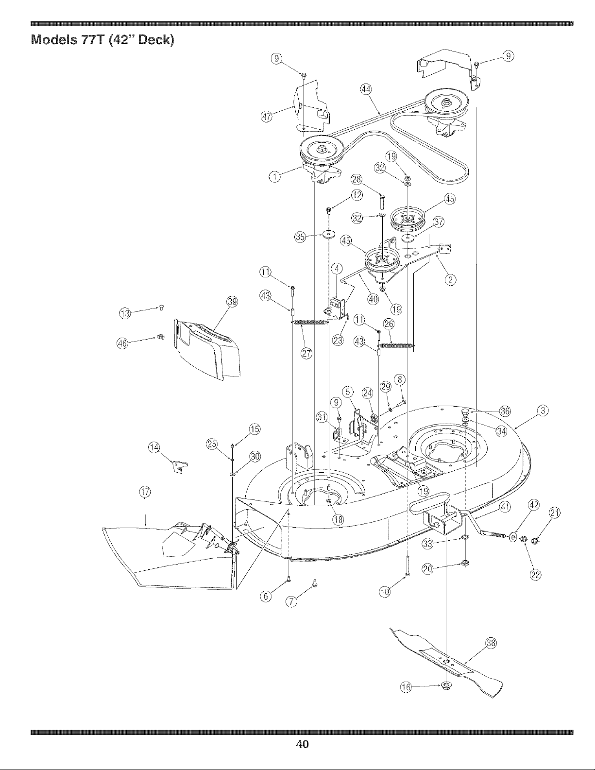
Models 77T (42" Deck)
@
4O

1 618-0624 SpindleAssembly,Pul,6,23" Dia
2 683-04138A BrakeAssembly,Deck
3 683-04165A DeckShell,42" (w/oWheelBrkt)
4 683-04167 BrakeAssembly,Deck
5 683-04228 Brkt,Ass'y,Deck,HangerLH
6 710-3015 Screw,1/4-20,,75,Gr5
7 710-1260A Screw,5/16-18,0,750
8 710-0528 Screw,5/16-18,1,250
9 710-0604A Screw,5/16-18,0,825
10 710-3085 Screw,3/8-16,3,50,Gr5
11 710-0778 Screw,1/4-20,1,500
12 710-3008 Screw,5/16-18,,75,Gr5
13 710-0134t CarriageScrew,, 1/4-20x ,62
14 783-1025 ChuteStop
15 712-3006 Nut, Hex,1/4-20,Gr5
16 712-0417A Nut, Flange,5/8-18
17 731-1032B ChuteAssembly,Discharge
18 712-04063 Nut, FlangeLock,5/16-18,GrF
19 750-04446 Spacr,3/8 ID x ,68 ODx 1,46Lg,
20 712-0641 Nut, Hex,M16-1,5
21 712-3083 Nut, HexLock, 1/2-13,Gr8
22 712-0206 Nut, Hex,1/2-13,Gr5
23 714-0104 Pin,Cot, ,072Dia, x 1,13Lg
24 717-04074 Gear,DeckAdiustment
25 726-0233
26 732-04280A
27 732-04287
28 710-0347
29 736-0119
30 736-0270
31 783-04740
32 736-0267
33 736-0225
34 736-0187
35 738-04166
38 738-04146
37 738-04162A
38 742-0616A
39 731-2363t
40 74_04379A
41 74_04269A
42 748-04069
43 750-0566A
44 754-04060B
45 756-04129
46 712-3087t
47 783-04327A
Nut, Push,,25 ID x ,50 OD
Spring,Exten,, ,75 Dia, x 6,375
Spring,Exten,, ,50 Dia, x 6,375
Screw,3/8-16x 1,75
Washer,Lock,5/16
Washer,Bell,,285 x,75x ,062
Deck EngagementCable Bracket
Washer,Flat,,385 x ,87x ,06
Washer,Lock,5/8, InternalTooth
Washer,Flat,,64 x 1,24x ,06
Spacer,Shoulder,,5000x ,1475
Plug,Screw,M16x 1,5
Spacer,Shoulder,,8840x ,190
Blade,21,23",Star3-in-1
MulchPlug
ControlRod,Brake
Deck Rod,FrontAdiustable
PivotCup,Deck Lift
Spacer,,280x ,372x 1,030
Belt,V-Type
Idler Pulley,4,25"Dia,
Wing Nut,1/4-20
Cover,Belt,6,00 Dia,
tOptional
Fora proper working machine
Jse Factory Approved Parts.
V-belts are designed to
_ngageand disengage safely.
Forpa#sand/or
ii
\
41
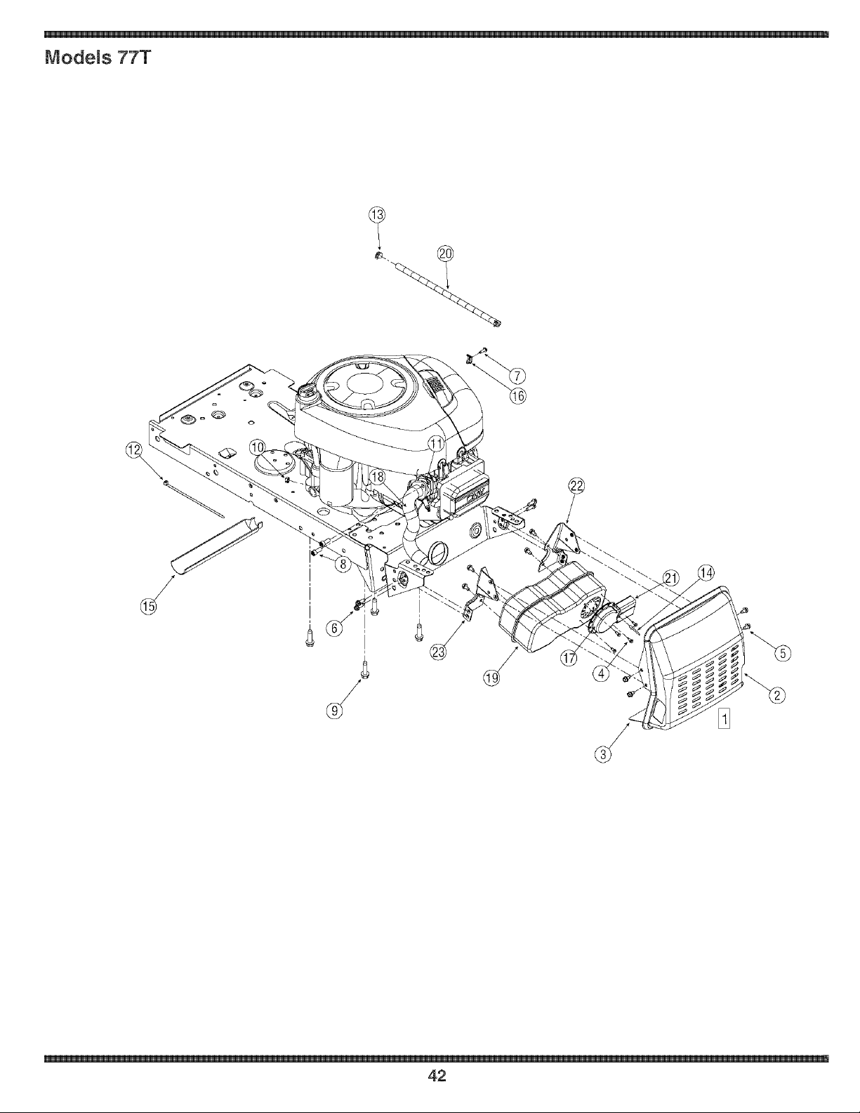
Models 77T
42

683-04256
783-04576
783-05006
710-0227
710-0599
710-0642
710q237
710-1314A
710-1315
712-0271
721-0208
725-0157
726_0205
728-04000
731-1682A
751B221535
751-0564B
751-10013
751-10162
751q0349
751-10353
783-04573
783-04574
MufflerShieldAssembly
MufflerShield
LowerHeatShield
Screw,#8q8 x ,50
Screw,1/4-20,0,500
Screw,1/4-20,0,750
Screw,#10_32,,625
SocketCap Screw,5/16_18,,625
Self-tappingScrew,3/8-16,1,25
HexSeresNut,1/4-20
ExhaustGasket
CableTie,7,4"
HoseClamp,,490
PopRivet,188x ,325
Oil DrainSleeve
CasingClamp
MufflerDeflector
ExhaustPipe
Muffler,SingleInlet
FuelLineHose
LongMufflerDeflector
LH MufflerBracket
RHMufflerBracket
For parts and/or
accessories
please call
1-866-840-6483,or
1-330-558-1220.
www.troybilt.com
\
43

For parts and/or
accessories
please call
Io866o840o6483,or
1-330o558o7220.
www.troybiJt.com
1
44

_IrSr
NOTES:
accessories
please call
1,330.558,7220.
45

For parts and/or
accessories
please calt
1o866o840o6483,or
1o330o558°722&
www.troybiJt.com
I
46

CAUFORNJA EMiSSiON CONTROL WARRANTY STATEMENT
YOUR WARRANTY RIGHTS AND OBLIGATIONS
The CaliforniaAir ResourcesBoardand MTDConsumerGroupInc are pleasedto explainthe evaporativeemissioncontrolsystemwarrantyon your2006 lawn
mower.In California,new lawnmowermust be designed,built andequippedto meet the State'sstringentanti-smogstandards.MTD ConsumerGroupInc must
warrantthe EECSon your lawnmowerfor the periodof time listedbelow providedthere has beenno abuse,neglector impropermaintenanceof your lawnmower.
YourEECSmayincludeparts such as thecarburetor,fuel-injectionsystem,the ignitionsystem,catalyticconverter,fuel tanks,fuel lines,fuelcaps, valves,
canisters,filters,vaporhoses,clamps,connectors,and otherassociatedemission-relatedcomponents.
Where a warrantaMe condition exists, MTDConsumer Group _newill repair your Hawnmower at no cost to you ineHudingdiagnosis, parts and Habor.
MANUFACTURER'S WARRANTY COVERAGE:
Thisevaporativeemissioncontrol systemis warrantedfor twoyears. If anyevaporativeemission-relatedpart onyour equipmentis defective,the partwill be
repairedor replacedby MTDConsumerGroup Inc.
OWNER'S WARRANTY RESPONSIBILITIES:
Asthe lawn mowerowner,you are responsiblefor performanceof the requiredmaintenancelistedin yourowner'smanual. MTDConsumerGroup Inc recom-
mendsthat you retain all receiptscoveringmaintenanceon your lawnmower,but MTDConsumerGroup Inccannot denywarrantysolelyfor the lackof receipts.
Asthe lawn mowerowner,you shouldhoweverbe awarethat MTDConsumerGroupInc maydenyyou warrantycoverageif yourlawn moweror a part has failed
dueto abuse,neglect, or impropermaintenanceor unapprovedmodifications.
Youare responsiblefor presentingyourlawn mowerto MTDConsumerGroupInc'sdistributioncenter or servicecenteras soonas the problemexists.The
warrantyrepairsshouldbecompletedin a reasonableamountof time, notto exceed30 days.If you havea questionregardingyour warrantycoverage,you should
contactthe MTDConsumerGroupIncService Departmentat 1-800-800-7310.
GENERAL EMISSIONS WARRANTY COVERAGE:
MTDConsumerGrouphc warrantsto the ultimatepurchaserandeachsubsequentpurchaserthat the lawnmoweris: Designed,built and equippedso as to
conformwithall applicableregulations;and freefrom defectsin materialsand workmanshipthatcausethe failure of a warrantedpart to be identicalin all material
respectsto that part as describedin MTDConsumerGroupInc's applicationfor certification.
Thewarranty periodbeginson the datethe lawnmoweris deliveredto an ultimatepurchaserorfirst placedinto service.Thewarranty periodis twoyears.
Subjectto certain conditionsand exclusionsas statedbelow,the warrantyon emission-relatedparts is as follows:
1. Anywarrantedpart that is not scheduledfor replacementas requiredmaintenanceinthe writteninstructionssupplied, is warrantedfor the warranty period
statedabove. If the part fails duringthe periodof warrantycoverage,the partwill be repairedor replacedby MTDConsumerGroupInc accordingto subsection
(4) below. Anysuch part repairedor replacedunderwarrantywill be warrantedfor the remainderof the period.
2. Anywarrantedpart that is scheduledonly for regular inspectioninthe writteninstructionssuppliedis warrantedfor the warranty periodstated above.Any such
part repairedor replacedunderwarrantywill be warrantedfor the remainingwarrantyperiod.
3. Any warrantedpart that is scheduledfor replacementas requiredmaintenanceinthe written instructionssuppliedis warrantedfor the periodof time beforethe
first scheduledreplacementdatefor that part. If the part failsbeforethe first scheduledreplacement,the partwill be repairedor replacedby MTDConsumer
GroupInc accordingto subsection(4) below. Anysuch part repairedor replacedunderwarrantywillbe warrantedfor the remainderof the periodpriorto the
first scheduledreplacementpointfor the part.
4. Repairor replacementof any warrantedpart underthewarrantyprovisionshereinmustbe performedat a warrantystationat no chargeto the owner.
5. Notwithstandingthe provisionsherein,warrantyservicesor repairswill beprovidedat all of our distributioncentersthat arefranchisedto servicethe subject
enginesor equipment.
6. The lawnmowerowner will not be chargedfor diagnosticlaborthat is directlyassociatedwithdiagnosisof a defective,emission-relatedwarrantedpart,
providedthat such diagnosticwork is performedat a warrantystation.
7. MTDConsumerGroupInc is liablefor damagesto other engineor equipmentcomponentsproximatelycaused bya failure underwarrantyof any warranted
part.
8. Throughoutthe lawnmowerwarrantyperiod stated above,MTDConsumerGroup Incwill maintaina supplyof warrantedparts sufficientto meetthe expected
demandfor suchparts.
9. Any replacementpart maybe usedin the performanceof any warrantymaintenanceor repairsand mustbe providedwithoutchargeto the owner.Suchuse will
not reducethe warrantyobligationsof MTDConsumerGroupInc.
10.Add-onor modified partsthat are notexemptedbythe Air ResourcesBoardmaynot beused.The use of any non-exemptedadd-onor modifiedparts by the
ultimatepurchaserwillbe groundsfor disallowinga warrantyclaims. MTDConsumerGroup Incwill not be liableto warrantfailures of warrantedparts caused
bythe use of a non-exemptedadd-onor modifiedpart.
WARRANTED PARTS:
The repairor replacementof any warrantedpartotherwiseeligiblefor warrantycoveragemaybe excludedfrom such warrantycoverageif MTDConsumerGroup
Inc demonstratesthat thelawn mowerhas been abused,neglected,or improperlymaintained,andthat such abuse, neglect,or impropermaintenancewasthe
directcauseof the need for repairor replacementof the part.That notwithstanding,any adjustmentof a componentthat hasa factory installed,and properly
operating,adjustmentlimiting device is still eligiblefor warrantycoverage.The following emissionwarrantyparts list are covered:FuelLine,Fuel Line Clamps
m

MANUFACTURER'S LIMITED WARRANTY FOR
®
The limitedwarrantyset forthbelowis givenbyTroy_BiltLLCwithrespect
to newmerchandisepurchasedand usedin the UnitedStates,its posses_
sionsandterritories.
"Troy_Bilt"warrantsthis productagainstdefectsin matedaland workmam
shipfor a periodof two(2) years commencingon thedate of original
purchaseandwill,at its option,repairor replace,freeof charge,any part
foundto be defectivein materialsor workmanship.This limitedwarranty
shallonly applyif this producthasbeen operatedand maintainedin
accordancewith the Operator'sManualfurnishedwiththe product,and
has notbeen subiectto misuse,abuse,commercialuse,neglect,accident,
impropermaintenance,alteration,vandalism,theft,fire,water,or damage
becauseof other perilor naturaldisaster.Damageresultingfromthe
installationor use ofany part, accessoryor attachmentnot approvedby
Troy_Biltfor use with theproduct(s)coveredby this manualwill voidyour
warrantyas to any resultingdamage.
Normalwearpartsarewarrantedto befree fromdefects in materialand
workmanshipfora periodof thirty (30) daysfrom thedate of purchase.
Normalwearpartsinclude,butare notlimitedto itemssuch as: batteries,
belts,blades,bladeadapters,grass bags,rider deck wheels,seats,snow
throwerskidshoes,shaveplates,augerspiralrubberandtires.
NOWTO OBTAIN SERVICE: Warranty service is available, WITH
PROOFOF PURCHASE,through your local authorizedservice
dealer. To locate the dealer in your area, check your Yellow Pages,
or contact Troy-Bilt LLC at RO. Box 361131,Cleveland, Ohio 44136-
0019, or can 1-866-840-6483 or 1-330-558-7220,or log on to our
Web site at www.troybilt.com.
This limitedwarrantydoesnot providecoverageinthe followingcases:
a. The engineor componentparts thereof.These itemsmay
carrya separatemanufacturer'swarranty.Referto applicable
manufacturer'swarrantyfor termsand conditions.
b. Logsplitterpumps,valves,andcylindershaveaseparateone
yearwarranty.
c. Routinemaintenanceitemssuch as lubricants,filters, blade
sharpening,tune_ups,brakeadiustments,clutch adiustments,
deckadiustments,and normaldeteriorationof the exteriorfinish
dueto use or exposure.
d. Servicecompletedbysomeoneotherthananauthorizedservice
dealer.
e. Troy_Biltdoesnot extendanywarrantyfor productssold or
exportedoutsideof the UnitedStates,its possessionsand
territories,exceptthosesold throughTroy_Bilt'sauthorized
channelsof exportdistribution.
f. Replacementpartsthatare notgenuineTroy_Biltparts.
g. Transportationchargesand servicecalls.
No impliedwarranty, includingany impliedwarranty of merchant°
ability of fitness for a particular purpose, applies after the applicable
period of express written warranty above as to the parts as identi-
fied. No other express warranty, whether written or oral, except as
mentioned above,given by any person or entity, including a dealer or
retailer,with respect to any product, shall bind Troy-Bilt. During the
period of the warranty,the exclusive remedy is repair or replacement
of the product as set forth above.
The provisions as set forth inthis warranty provide the sole and
exclusive remedyarising from the sale. Troy-Bilt shall not be liable
for incidental or consequential loss or damage including, without
limitation, expenses incurred for substitute or replacement lawn care
services or for rental expenses to temporarily replace a warranted
product.
Somestatesdo not allowtheexclusionor limitationof incidentalor
consequentialdamages,or limitationson howlong an impliedwarranty
lasts,so the aboveexclusionsor limitationsmaynotapplyto you.
In no eventshall recoveryof any kind be greaterthanthe amountof the
purchasepriceof the productsold. Alteration of safety features of the
product shall void this warranty. Youassumethe risk and liability for
loss,damage,or iniuryto youand yourpropertyand/or to othersand their
propertyarisingout of the misuseor inabilityto use the product.
This limitedwarrantyshall notextendto anyoneotherthanthe original
purchaseror to the personfor whom it was purchasedas a gift.
HOWSTATELAW RELATESTO THISWARRANTY:Thislimitedwar-
rantygh,'esyouspecificlegalrights,andyou mayalso haveother rights
whichvaryfromstateto state.
IMPORTANT:OwnermustpresentOriginalProofof Purchaseto obtain
warrantycoverage.
TROYBILT LLC, P.O. BOX 361131 CLEVELAN D, OHIO 44136-0019; Phone: 1(866} 840-6483, 1-330-558-7220