
P. O. Box 1386, 97 KENT AVENUE, KITCHENER, ON N2G 4J1
Printed In USA
OperatOr’s Manual
Safe Operation Practices • Set-Up • Operation • Maintenance • Service • Troubleshooting • Warranty
WARNING
READ AND FOLLOW ALL SAFETY RULES AND INSTRUCTIONS IN THIS MANUAL
BEFORE ATTEMPTING TO OPERATE THIS MACHINE.
FAILURE TO COMPLY WITH THESE INSTRUCTIONS MAY RESULT IN PERSONAL INJURY.
769-08519
11.29.12
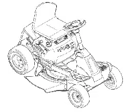
Lawn Tractor — 26J Mini-Rider

Customer Support
Please do
NOT
return the unit to the retailer from which it was purchased, without first contacting Customer Support.
If you have difficulty assembling this product or have any questions regarding the controls, operation, or maintenance of
this machine, you can seek help from the experts. Choose from the options below:
◊ Visit our web at www.troybilt.ca
◊ Locate your nearest dealer from Customer Support: 1-800-668-1238
◊ Contact Troy Bilt • P.O. Box 1386 • 97 Kent Avenue • Kitchener, Ontario, Canada • N2G 4J1
To The Owner
1
2
Safe Operation Practices ........................................ 3
Assembly & Set-Up .................................................. 9
Controls & Features ................................................13
Operation ................................................................16
Maintenance & Adjustment .................................19
Service .................................................................... 23
Troubleshooting .................................................... 27
Replacement Parts ................................................ 28
Attachments & Accessories .................................. 29
Emission control warranty statement ................. 30
Warranty ................................................................ 32
Table of Contents
Thank you for purchasing your new equipment. It was carefully
engineered to provide excellent performance when properly
operated and maintained.
Please read this entire manual prior to operating the equipment.
It instructs you how to safely and easily set up, operate and
maintain your machine. Please be sure that you, and any other
persons who will operate the machine, carefully follow the
recommended safety practices at all times. Failure to do so could
result in personal injury or property damage.
All information in this manual is relative to the most recent
product information available at the time of printing. Review
this manual frequently to familiarize yourself with the machine,
its features and operation. Please be aware that this Operator’s
Manual may cover a range of product specifications for
various models. Characteristics and features discussed and/or
illustrated in this manual may not be applicable to all models.
The manufacturer reserves the right to change product
specifications, designs and equipment without notice and
without incurring obligation.
If you have any problems or questions concerning the machine,
phone your local service dealer or contact us directly. Customer
Support telephone numbers, website address and mailing
address can be found on this page. We want to ensure your
complete satisfaction at all times.
Throughout this manual, all references to right and left side of the
machine are observed from the operating position.
The engine manufacturer is responsible for all engine-related
issues with regards to performance, power-rating, specifications,
warranty and service. Please refer to the engine manufacturer’s
Owner’s/Operator’s Manual, packed separately with your
machine, for more information.
Thank You
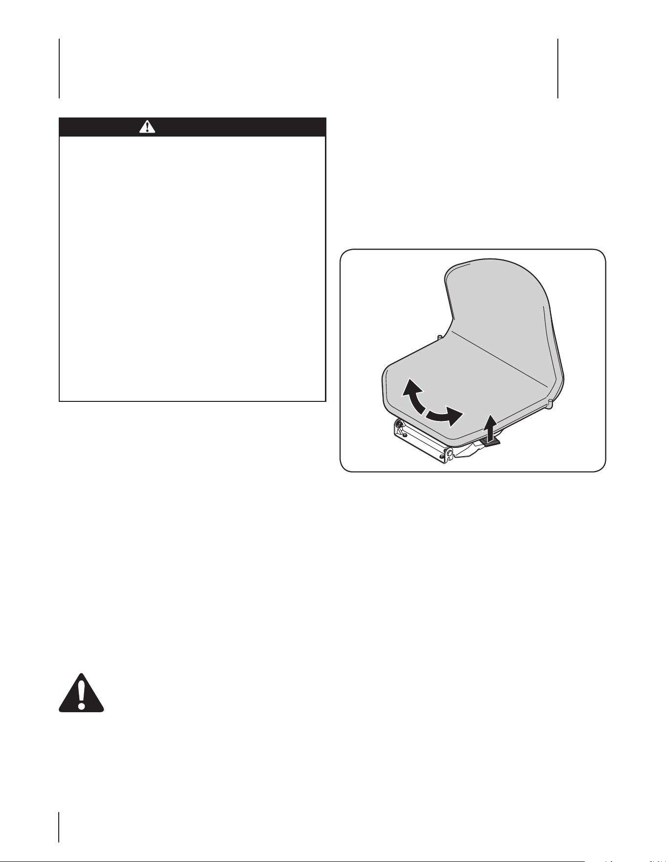
Record Product Information
Before setting up and operating your new equipment, please
locate the model plate on the equipment and record the
information in the provided area to the right. You can locate the
model plate under the operator’s seat. Flip the seat forward to
view the model plate. This information will be necessary, should
you seek technical support via our web site or with your local
dealer.
Model NuMber
Serial NuMber

Important Safe Operation Practices
2
3
General Operation
1. Read, understand, and follow all instructions on the
machine and in the manual(s) before attempting to
assemble and operate. Keep this manual in a safe place for
future and regular reference and for ordering replacement
parts.
2. Be familiar with all controls and their proper operation.
Know how to stop the machine and disengage them
quickly.
3. Never allow children under 14 years of age to operate this
machine. Children 14 and over should read and understand
the instructions and safe operation practices in this manual
and on the machine and should be trained and supervised
by an adult.
4. Never allow adults to operate this machine without proper
instruction.
5. To help avoid blade contact or a thrown object injury,
keep bystanders, helpers, children and pets at least 75 feet
from the machine while it is in operation. Stop machine if
anyone enters the area.
6. Thoroughly inspect the area where the equipment is to be
used. Remove all stones, sticks, wire, bones, toys, and other
foreign objects which could be picked up and thrown by
the blade(s). Thrown objects can cause serious personal
injury.
7. Plan your mowing pattern to avoid discharge of material
toward roads, sidewalks, bystanders and the like. Also,
avoid discharging material against a wall or obstruction
which may cause discharged material to ricochet back
toward the operator.
8. Always wear safety glasses or safety goggles during
operation and while performing an adjustment or repair
to protect your eyes. Thrown objects which ricochet can
cause serious injury to the eyes.
9. Wear sturdy, rough-soled work shoes and close-fitting
slacks and shirts. Loose fitting clothes and jewelry can be
caught in movable parts. Never operate this machine in
bare feet or sandals.
10. Be aware of the mower and attachment discharge direction
and do not point it at anyone. Do not operate the mower
without the discharge cover or entire grass catcher in its
proper place.
11. Do not put hands or feet near rotating parts or under the
cutting deck. Contact with the blade(s) can amputate
hands and feet.
12. A missing or damaged discharge cover can cause blade
contact or thrown object injuries.
13. Stop the blade(s) when crossing gravel drives, walks, or
roads and while not cutting grass.
14. Watch for traffic when operating near or crossing
roadways. This machine is not intended for use on any
public roadway.
15. Do not operate the machine while under the influence of
alcohol or drugs.
WARNING: This symbol points out important safety instructions which, if not followed,
could endanger the personal safety and/or property of yourself and others. Read and follow
all instructions in this manual before attempting to operate this machine. Failure to comply
with these instructions may result in personal injury.
When you see this symbol. HEED ITS WARNING!
WARNING: Engine Exhaust, some of its constituents, and certain vehicle components
contain or emit chemicals known to State of California to cause cancer and birth defects or
other reproductive harm.
WARNING: Battery posts, terminals, and related accessories contain lead and lead
compounds, chemicals known to the State of California to cause cancer and reproductive
harm. Wash hands after handling.
DANGER: This machine was built to be operated according to the safe operation practices in
this manual. As with any type of power equipment, carelessness or error on the part of the
operator can result in serious injury. This machine is capable of amputating fingers, hands,
toes and feet and throwing objects. Failure to observe the following safety instructions could
result in serious injury or death.

4 Section 2 — important Safe operation practiceS
16. Mow only in daylight or good artificial light.
17. Never carry passengers.
18. Disengage blade(s) before shifting into reverse. Back up
slowly. Always look down and behind before and while
backing to avoid a back-over accident.
19. Slow down before turning. Operate the machine smoothly.
Avoid erratic operation and excessive speed.
20. Disengage blade(s), set parking brake, stop engine and
wait until the blade(s) come to a complete stop before
removing grass catcher, emptying grass, unclogging chute,
removing any grass or debris, or making any adjustments.
21. Never leave a running machine unattended. Always turn
off blade(s), place transmission in neutral, set parking
brake, stop engine and remove key before dismounting.
22. Use extra care when loading or unloading the machine into
a trailer or truck. This machine should not be driven up or
down ramp(s), because the machine could tip over, causing
serious personal injury. The machine must be pushed
manually on ramp(s) to load or unload properly.
23. Muffler and engine become hot and can cause a burn. Do
not touch.
24. Check overhead clearances carefully before driving under
low hanging tree branches, wires, door openings etc.,
where the operator may be struck or pulled from the
machine, which could result in serious injury.
25. Disengage all attachment clutches, depress the brake
pedal completely and shift into neutral before attempting
to start engine.
26. Your machine is designed to cut normal residential grass of
a height no more than 10”. Do not attempt to mow through
unusually tall, dry grass (e.g., pasture) or piles of dry leaves.
Dry grass or leaves may contact the engine exhaust and/or
build up on the mower deck presenting a potential fire
hazard.
27. Use only accessories and attachments approved for this
machine by the machine manufacturer. Read, understand
and follow all instructions provided with the approved
accessory or attachment.
28. Data indicates that operators, age 60 years and above, are
involved in a large percentage of riding mower-related
injuries. These operators should evaluate their ability
to operate the riding mower safely enough to protect
themselves and others from serious injury.
29. If situations occur which are not covered in this manual, use
care and good judgment. Contact your customer service
representative for assistance.
Slope Operation
Slopes are a major factor related to loss of control and tip-over
accidents which can result in severe injury or death. All slopes
require extra caution. If you cannot back up the slope or if you
feel uneasy on it, do not mow it.
For your safety, use the slope gauge included as part of this
manual to measure slopes before operating this machine on
a sloped or hilly area. If the slope is greater than 12 degrees as
shown on the slope gauge, do not operate this machine on that
area or serious injury could result.
Do:
1. Mow up and down slopes, not across. Exercise extreme
caution when changing direction on slopes.
2. Watch for holes, ruts, bumps, rocks, or other hidden
objects. Uneven terrain could overturn the machine. Tall
grass can hide obstacles.
3. Use slow speed. Choose a low enough speed setting so
that you will not have to stop or shift while on the slope.
Tires may lose traction on slopes even though the brakes
are functioning properly. Always keep machine in gear
when going down slopes to take advantage of engine
braking action.
4. Follow the manufacturer’s recommendations for wheel
weights or counterweights to improve stability.
5. Use extra care with grass catchers or other attachments.
These can change the stability of the machine.
6. Keep all movement on the slopes slow and gradual. Do
not make sudden changes in speed or direction. Rapid
engagement or braking could cause the front of the
machine to lift and rapidly flip over backwards which could
cause serious injury.
7. Avoid starting or stopping on a slope. If tires lose traction,
disengage the blade(s) and proceed slowly straight down
the slope.
Do Not:
1. Do not turn on slopes unless necessary; then, turn slowly
and gradually downhill, if possible.
2. Do not mow near drop-offs, ditches or embankments. The
mower could suddenly turn over if a wheel is over the edge
of a cliff, ditch, or if an edge caves in.
3. Do not try to stabilize the machine by putting your foot on
the ground.
4. Do not use a grass catcher on steep slopes.
5. Do not mow on wet grass. Reduced traction could cause
sliding.
6. Do not shift to neutral and coast downhill. Over-speeding
may cause the operator to lose control of the machine
resulting in serious injury or death.
7. Do not tow heavy pull behind attachments (e.g. loaded
dump cart, lawn roller, etc.) on slopes greater than 5
degrees. When going down hill, the extra weight tends to
push the tractor and may cause you to loose control (e.g.
tractor may speed up, braking and steering ability are
reduced, attachment may jack-knife and cause tractor to
overturn).
Children
1. Tragic accidents can occur if the operator is not alert to the
presence of children. Children are often attracted to the
machine and the mowing activity. They do not understand
the dangers. Never assume that children will remain where
you last saw them.
a. Keep children out of the mowing area and in
watchful care of a responsible adult other than the
operator.

5Section 2 — important Safe operation practiceS
b. Be alert and turn machine off if a child enters the
area.
c. Before and while backing, look behind and down for
small children.
d. Never carry children, even with the blade(s) shut off.
They may fall off and be seriously injured or interfere
with safe machine operation.
e. Use extreme care when approaching blind corners,
doorways, shrubs, trees or other objects that may
block your vision of a child who may run into the
path of the machine.
f. To avoid back-over accidents, always disengage
the cutting blade(s) before shifting into Reverse.
If equipped, the “Reverse Caution Mode” should
not be used when children or others are around.
g. Keep children away from hot or running engines.
They can suffer burns from a hot muffler.
h. Remove key when machine is unattended to
prevent unauthorized operation.
2. Never allow children under 14 years of age to operate this
machine. Children 14 and over should read and understand
the instructions and safe operation practices in this manual
and on the machine and should be trained and supervised
by an adult.
Towing
1. Tow only with a machine that has a hitch designed for
towing. Do not attach towed equipment except at the
hitch point.
2. Follow the manufacturers recommendation for weight
limits for towed equipment and towing on slopes.
3. Never allow children or others in or on towed equipment.
4. On slopes, the weight of the towed equipment may cause
loss of traction and loss of control.
5. Always use extra caution when towing with a machine
capable of making tight turns (e.g. “zero-turn” ride-on
mower). Make wide turns to avoid jack-knifing.
6. Travel slowly and allow extra distance to stop.
7. Do not shift to neutral and coast downhill.
Service
Safe Handling of Gasoline:
1. To avoid personal injury or property damage use extreme
care in handling gasoline. Gasoline is extremely
flammable and the vapors are explosive. Serious
personal injury can occur when gasoline is spilled on
yourself or your clothes which can ignite. Wash your skin
and change clothes immediately.
a. Use only an approved gasoline container.
b. Never fill containers inside a vehicle or on a truck
or trailer bed with a plastic liner. Always place
containers on the ground away from your vehicle
before filling.
c. When practical, remove gas-powered equipment
from the truck or trailer and refuel it on the ground.
If this is not possible, then refuel such equipment on
a trailer with a portable container, rather than from a
gasoline dispenser nozzle.
d. Keep the nozzle in contact with the rim of the fuel
tank or container opening at all times until fueling is
complete. Do not use a nozzle lock-open device.
e. Extinguish all cigarettes, cigars, pipes and other
sources of ignition.
f. Never fuel machine indoors.
g. Never remove gas cap or add fuel while the engine
is hot or running. Allow engine to cool at least two
minutes before refueling.
h. Never over fill fuel tank. Fill tank to no more than ½
inch below bottom of filler neck to allow space for
fuel expansion.
i. Replace gasoline cap and tighten securely.
j. If gasoline is spilled, wipe it off the engine and
equipment. Move machine to another area. Wait 5
minutes before starting the engine.
k. To reduce fire hazards, keep machine free of grass,
leaves, or other debris build-up. Clean up oil or fuel
spillage and remove any fuel soaked debris.
l. Never store the machine or fuel container inside
where there is an open flame, spark or pilot light
as on a water heater, space heater, furnace, clothes
dryer or other gas appliances.
m. Allow a machine to cool at least five minutes before
storing.
General Service
1. Never run an engine indoors or in a poorly ventilated area.
Engine exhaust contains carbon monoxide, an odorless,
and deadly gas.
2. Before cleaning, repairing, or inspecting, make certain the
blade(s) and all moving parts have stopped. Disconnect the
spark plug wire and ground against the engine to prevent
unintended starting.
3. Periodically check to make sure the blades come to
complete stop within approximately (5) five seconds after
operating the blade disengagement control. If the blades
do not stop within the this time frame, your machine
should be serviced professionally by an authorized Service
Dealer.
4. Check brake operation frequently as it is subjected to wear
during normal operation. Adjust and service as required.
5. Check the blade(s) and engine mounting bolts at frequent
intervals for proper tightness. Also, visually inspect blade(s)
for damage (e.g., excessive wear, bent, cracked). Replace
the blade(s) with the original equipment manufacturer’s
(O.E.M.) blade(s) only, listed in this manual. “Use of parts
which do not meet the original equipment specifications
may lead to improper performance and compromise
safety!”

6 Section 2 — important Safe operation practiceS
6. Mower blades are sharp. Wrap the blade or wear gloves,
and use extra caution when servicing them.
7. Keep all nuts, bolts, and screws tight to be sure the
equipment is in safe working condition.
8. Never tamper with the safety interlock system or other
safety devices. Check their proper operation regularly.
9. After striking a foreign object, stop the engine, disconnect
the spark plug wire(s) and ground against the engine.
Thoroughly inspect the machine for any damage. Repair
the damage before starting and operating.
10. Never attempt to make adjustments or repairs to the
machine while the engine is running.
11. Grass catcher components and the discharge cover are
subject to wear and damage which could expose moving
parts or allow objects to be thrown. For safety protection,
frequently check components and replace immediately
with original equipment manufacturer’s (O.E.M.) parts only,
listed in this manual. “Use of parts which do not meet the
original equipment specifications may lead to improper
performance and compromise safety!”
12. Do not change the engine governor settings or over-speed
the engine. The governor controls the maximum safe
operating speed of the engine.
13. Maintain or replace safety and instruction labels, as
necessary.
14. Observe proper disposal laws and regulations for gas, oil,
etc. to protect the environment.
15. According to the Consumer Products Safety Commission
(CPSC) and the U.S. Environmental Protection Agency (EPA),
this product has an Average Useful Life of seven (7) years,
or 270 hours of operation. At the end of the Average Useful
Life have the machine inspected annually by an authorized
service dealer to ensure that all mechanical and safety
systems are working properly and not worn excessively.
Failure to do so can result in accidents, injuries or death.
Do not modify engine
To avoid serious injury or death, do not modify engine in any
way. Tampering with the governor setting can lead to a runaway
engine and cause it to operate at unsafe speeds. Never tamper
with factory setting of engine governor.
Notice Regarding Emissions
Engines which are certified to comply with California and federal
EPA emission regulations for SORE (Small Off Road Equipment)
are certified to operate on regular unleaded gasoline, and
may include the following emission control systems: Engine
Modification (EM), Oxidizing Catalyst (OC), Secondary Air
Injection (SAI) and Three Way Catalyst (TWC) if so equipped.
Spark Arrestor
WARNING! This machine is equipped with an
internal combustion engine and should not be used
on or near any unimproved forest-covered,
brushcovered or grass-covered land unless the
engine’s exhaust system is equipped with a spark
arrester meeting applicable local or state laws (if
any).
If a spark arrester is used, it should be maintained in effective
working order by the operator.
A spark arrester for the muffler is available through your nearest
engine authorized service dealer.
WARNING! Your Responsibility—Restrict the use of this power machine to persons who read, understand and
follow the warnings and instructions in this manual and on the machine.
SAVE THESE INSTRUCTIONS!
7Section 2 — important Safe operation practiceS
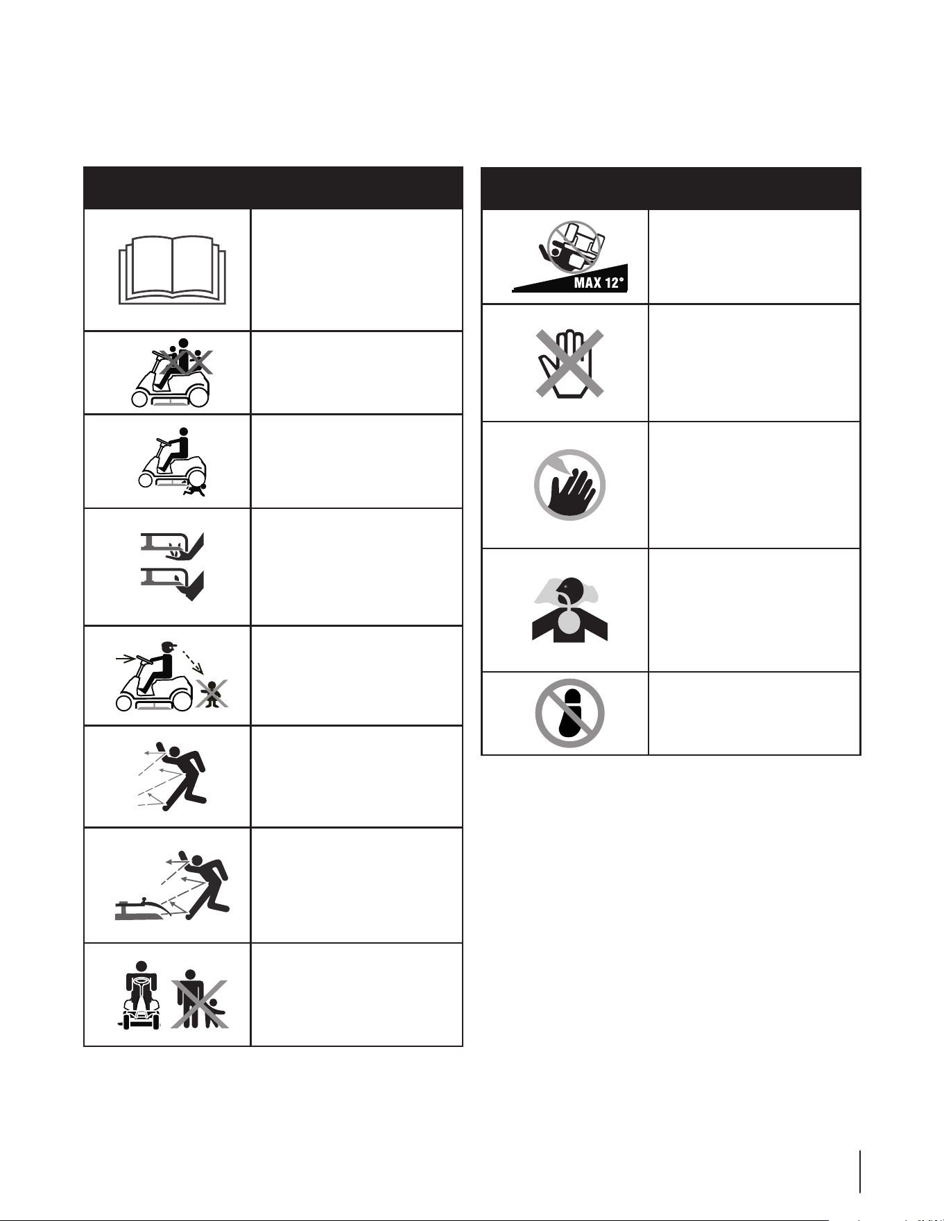
Symbol Description
READ THE OPERATOR’S
MANUAL(S)
Read, understand, and follow
all instructions in the manual(s)
before attempting to assemble
and operate
DANGER— ROTATING BLADES
Never carry passengers. Never
carry children, even with the
blades off.
DANGER— ROTATING BLADES
To avoid a back-over accident,
keep children away from the
machine while it is in operation.
WARNING— ROTATING BLADES
Do not put hands or feet near
rotating parts or under the
cutting deck. Contact with the
blade(s) can amputate hands and
feet.
DANGER— ROTATING BLADES
Always look down and behind
before and while backing to
avoid a back-over accident.
WARNING—THROWN OBJECTS
This machine may pick up and
throw and objects which can
cause serious personal injury.
WARNING—THROWN OBJECTS
This machine may pick up and
throw and objects which can
cause serious personal injury.
BYSTANDERS
Keep bystanders, helpers,
children and pets at least 75 feet
from the machine while it is in
operation.
Symbol Description
WARNING— SLOPE OPERATION
Do not operate this machine on
a slope greater than 12 degrees.
WARNING— HOT SURFACE
Engine parts, especially the
muffler, become extremely hot
during operation. Allow engine
and muffler to cool before
touching.
DANGER — ROTATING BLADES
To reduce the risk of injury, keep
hands and feet away. Do not
operate unless discharge cover or
grass catcher is in its proper place.
If damaged, replace immediately.
WARNING— CARBON MONOXIDE
Never run an engine indoors
or in a poorly ventilated area.
Engine exhaust contains carbon
monoxide, an odorless and
deadly gas.
DANGER— ROTATING BLADES
Do not step on the cutting deck.
Safety Symbols
This page depicts and describes safety symbols that may appear on this product. Read, understand, and follow all instructions on the
machine before attempting to assemble and operate.
8 Section 2 — important Safe operation practiceS
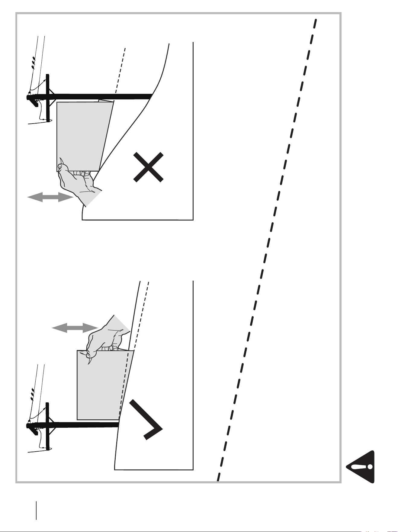
(OK) (TOO STEEP)
USE THIS SLOPE GAUGE TO DETERMINE
IF A SLOPE IS TOO STEEP FOR SAFE OPERATION!
To check the slope, proceed as follows:
1. Remove this page and fold along the dashed line.
2. Locate a vertical object on or behind the slope (e.g. a pole, building, fence, tree, etc.)
3. Align either side of the slope gauge with the object (See Figure 1 and Figure 2 ).
4. Adjust gauge up or down until the left corner touches the slope (See Figure 1 and Figure 2).
5. If there is a gap below the gauge, the slope is too steep for safe operation (See Figure 2 above).
12° dashed line
Slope Gauge
Figure 2Figure 1
12° Slope
12° Slope
WARNING! Slopes are a major factor related to tip-over and roll-over accidents which can result in severe injury or death.
Do not operate machine on slopes in excess of 12 degrees. All slopes require extra caution. If you cannot back up the slope
or if you feel uneasy on it, do not mow it. Always mow up and down slopes, never across the face of slopes.
Assembly & Set-Up
3
9
Contents of Hardware Pack
Before beginning installation, remove all the contents from the
crate and all the hardware from the pack from to make sure
everything is present. Hardware is listed below. Part numbers are
shown in parentheses.
• Hitch Plate (783-07208)
• Seat Mounting Bracket (783-07168) and hardware
(738-0140 & 712-04063)
Recommended Tools for Assembly
• 3/8” Wrench (or socket)
• 1/2” Wrench (or socket)
• Phillips Screw Driver
• 1/4” Drive Ratchet
• 9/16” Socket or wrench
• 7/16” wrench
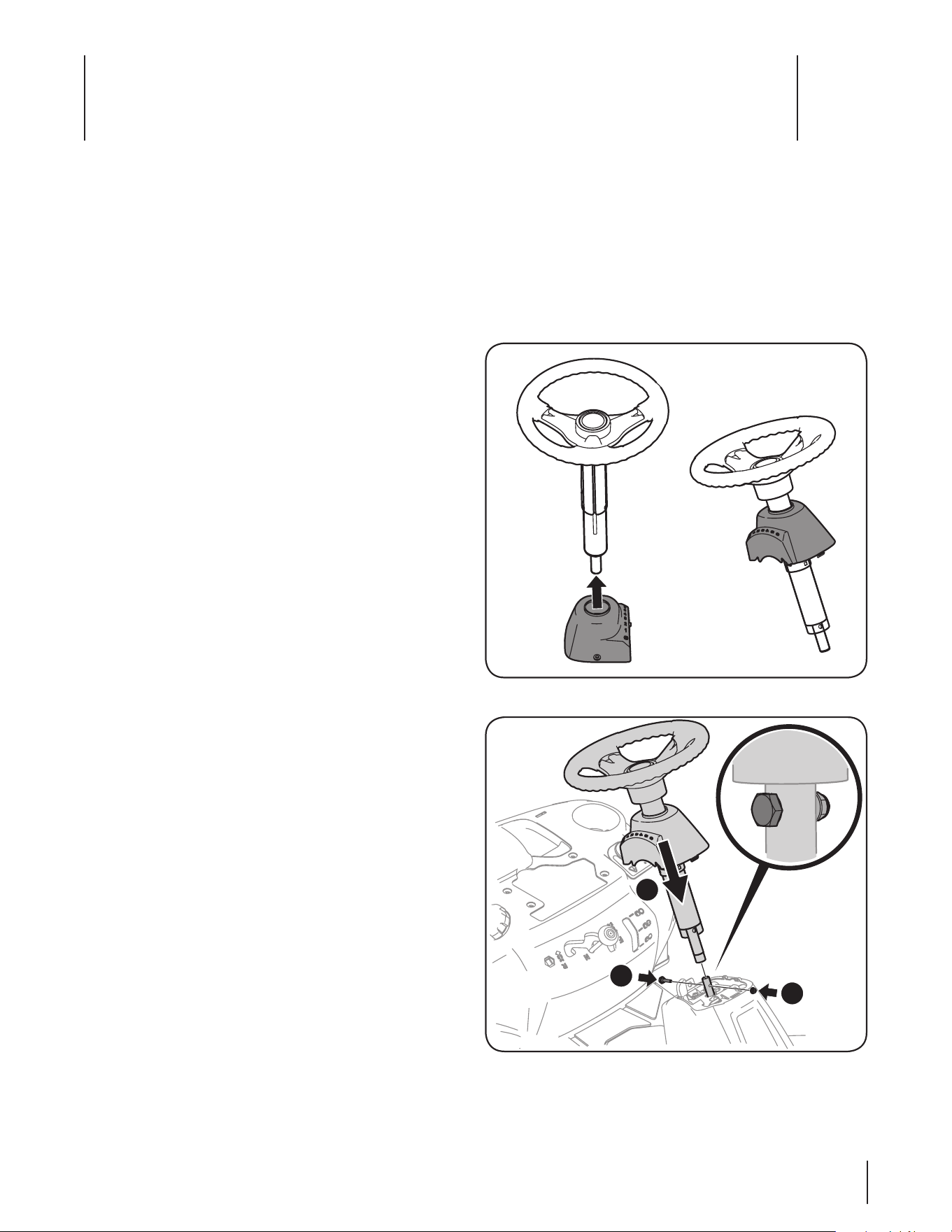
Installing The Steering Wheel Assembly
If the steering wheel assembly for your tractor did not come
alredy installed, follow the steps below:
1. Slide the pedestal cap onto the steering shaft so that when
the steering shaft is installed on the tractor, the pedestal
cap will be upright as shown in Figure 3-1.
2. Remove the shoulder bolt and lock nut from the steering
shaft on the tractor and retain for later steps.
3. With the steering wheel assembly upright and positioned
over the lower steering shaft on the tractor, align the
steering wheel so that with the tractor wheels straight, the
large opening on the steering wheel is facing forward.
4. Lower the steering wheel assembly onto the lower steering
shaft and secure with the shoulder bolt and lock nut
previously removed. See Figure 3-2.
NOTE: Be sure to align the shoulder bolt so that the head
of the bolt fits into the larger hole provided on the upper
steering shaft once tightened.
5. Tighten the shoulder bolt and lock nut using 9/16” wrench
and a 7/16” wrench or socket.
Contents of Crate
• One Riding Mower • One Seat Assembly • One Steering Pedestal Cap
• One Steering Wheel/Shaft Assembly • One Rear Engine Cover • One Discharge Chute Assembly
• One Oil Drain Sleeve • One Hardware Pack • One Engine Operator’s Manual
• One Riding Mower Operator’s
Manual
Figure 3-1
Figure 3-2
1
2
2
Assembly & Set-Up
3
9
10 Section 3— ASSembly & Set-Up
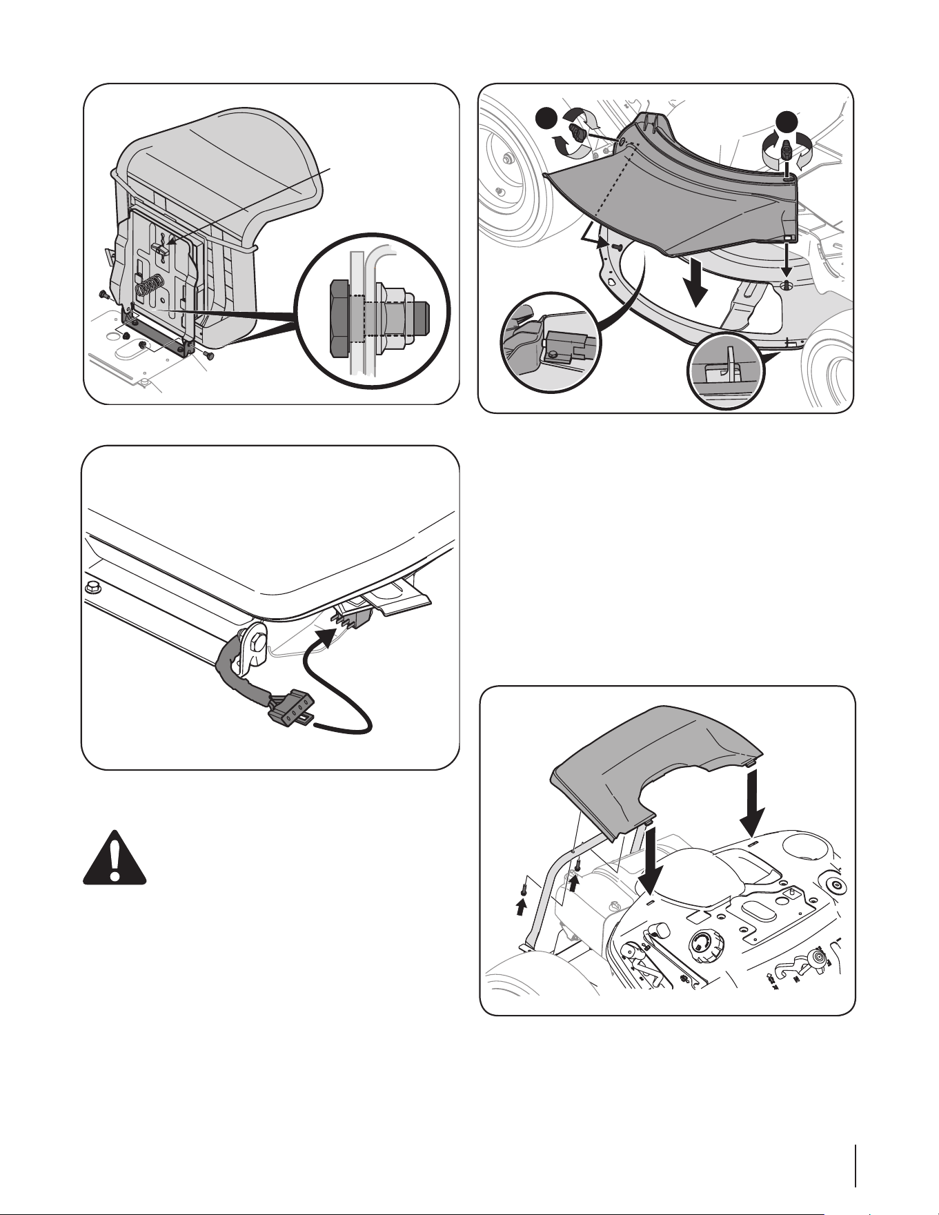
4. Position the seat assembly in place over the seat mounting
bracket aligning the holes provided. Secure with shoulder
bolts and locknuts bolts previously removed. See Figure
3-7.
5. Plug the safety harness on the seat into the wiring harness
on the unit as shown in Figure 3-8.
6. To adjust the position of the seat, loosen the adjustment
knob on the bottom of the seat. Slide the seat forward or
backward as desired. Retighten the adjustment knob. Refer
to Figure 3-7.
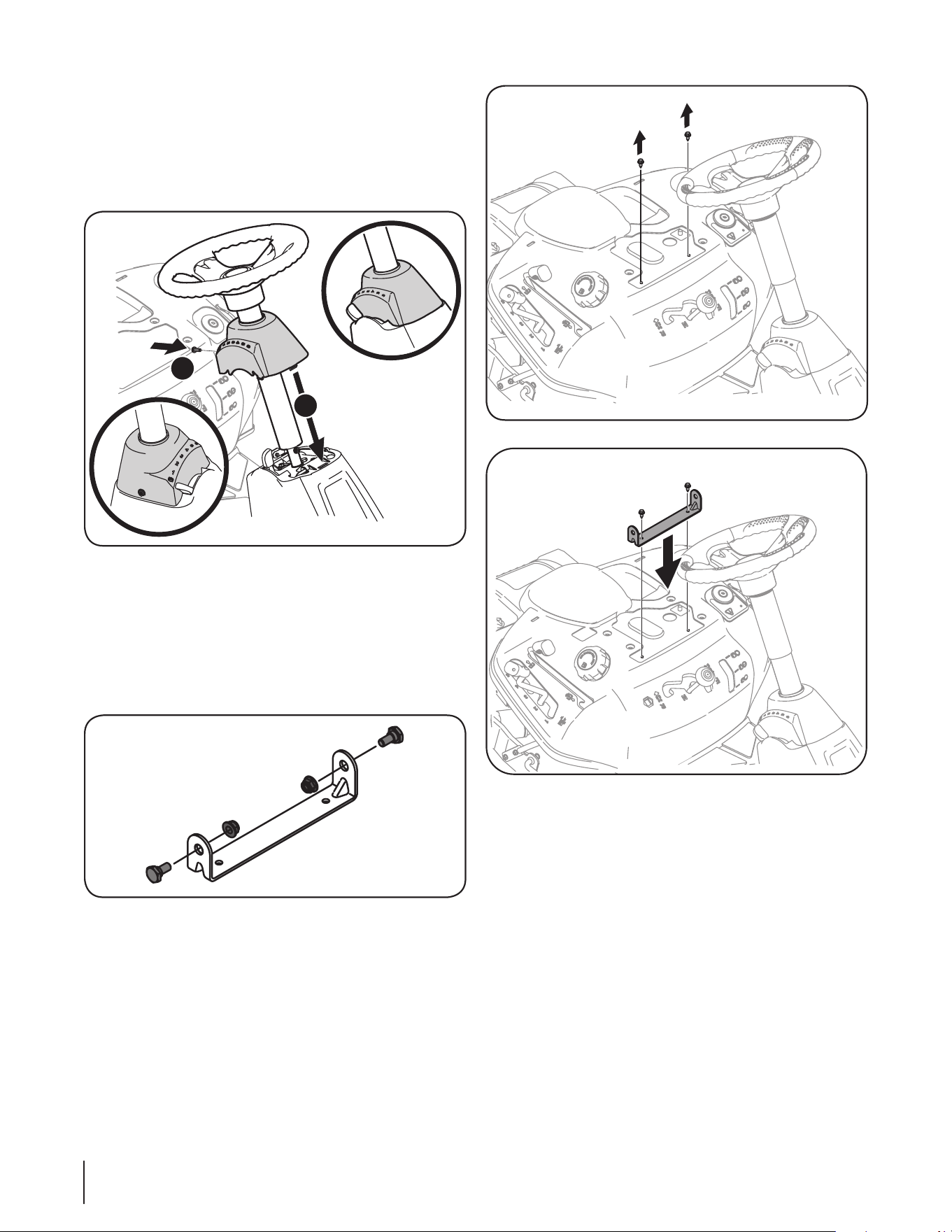
6. Remove the pedestal cap mount pan head screw that
is factory installed and located on the tractor’s steering
console. Retain the screw for later instructions.
7. Slide the pedestal cap down onto the tractor (1) and slighty
rotate to the right to clip into place. Secure the pedestal
with the pan head screw (2) previously removed. See Figure
3-3.
Attaching The Seat
If the seat for your tractor was not attached at the factory, follow
the applicable instructions below to attach it.
1. Remove the shoulder bolts and lock nuts from the seat
mounting bracket included in your hardware pack. See
Figure 3-4.
2. Using a /-inch drive ratchet with a /” socket, remove the
two self-tapping bolts factory installed on the tractor. See
Figure 3-5.
3. Position the seat mounting bracket assembly in place over
the holes, as shown in Figure 3-6. Secure mounting bracket
with the self-tapping bolts previously removed.
CAUTION: Do not use any type of power tool (e.g. impact gun
or electric drill with nut driver attached) when tightening the
self-tapping bolts to attach the seat bracket.
1
2
Figure 3-3
Figure 3-4
Figure 3-5
Figure 3-6
10
11Section 3 — ASSembly & Set-Up
Installing The Deck Chute
WARNING! NEVER operate this tractor without
either the mulch plug or deck chute installed.
1. Remove the wing knobs installed on the mowing deck and
retain for later installation.
2. Install the deck chute into the deck discharge opening on
the deck. The studs on the deck surface will fit through the
holes on the upper portion of the deck chute. The small tab
on the deck lip area will fit through the square cutout on
the lower portion of the deck chute. See Figure 3-9.
Note: Make certain that the upper-rear portion of deck
chute is depressing the safety switch located on the deck
surface. The engine will not start without the deck chute
properly in place.
3. Secure the deck chute by tightening the wing knobs
removed earlier. See Figure 3-9.
Install The Rear Engine Cover
1. Remove the two factory installed hex screws located on the
rear engine cover. Retain the screws for later instructions.
See Figure 3-10.
2. Install the rear engine cover by positioning it in place as
shown in Figure 3-10. Tip the engine cover forward to fit it
into the slots provided, then rotate it backwards to align
the mounting holes.
3. Secure the cover with the two hex screws previously
removed. Do not to over-tighten.
Figure 3-9
Figure 3-10
Figure 3-7
Figure 3-8
1
2
Adjustment Knob
11
12 Section 3— ASSembly & Set-Up
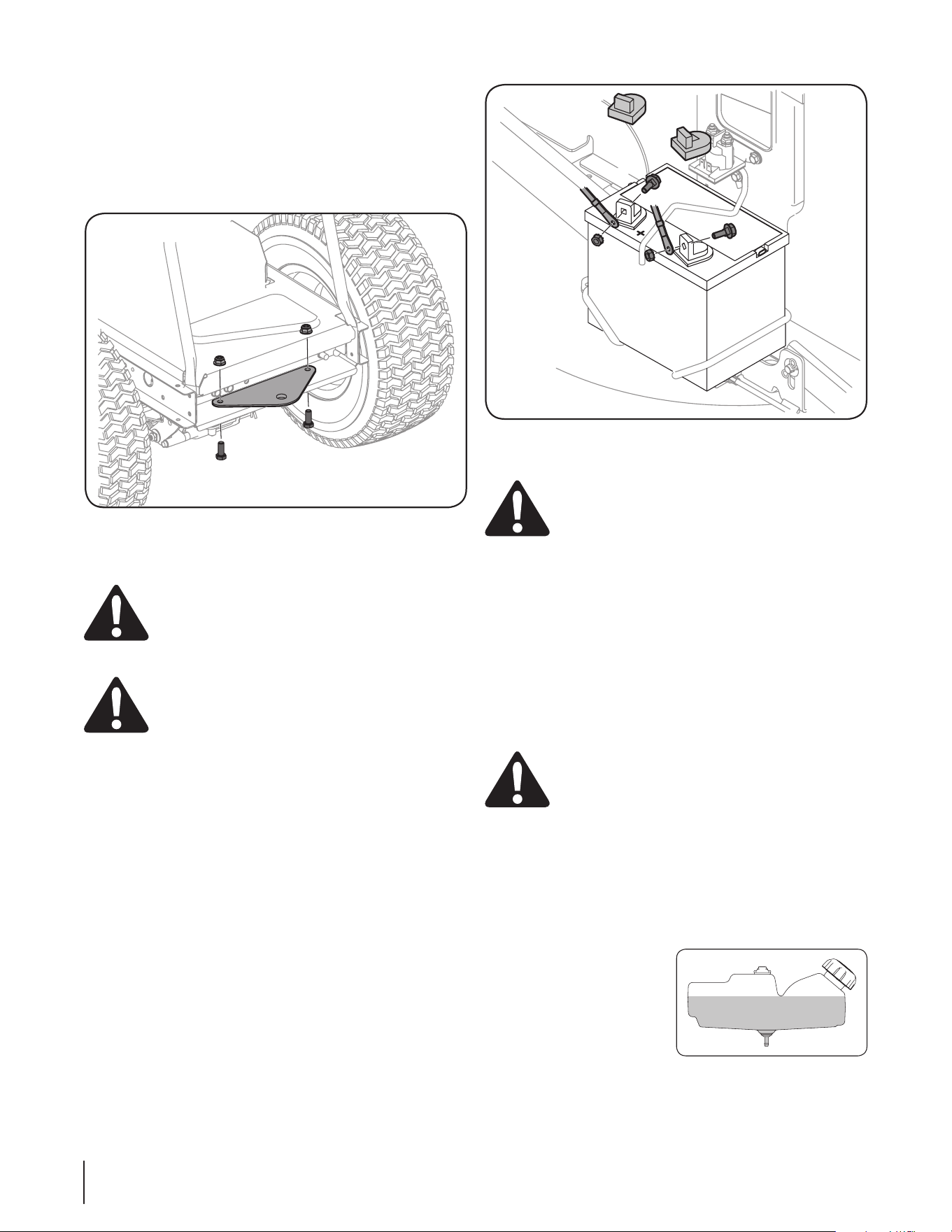
Installing the Hitch Plate
1. Remove the factory installed hitch plate mounting
hardware located on the rear of the tractor. See Figure 3-11.
2. Position the hitch plate with the flat side up, as shown in
Fig. 3-11. Secure using two bolts and hex nuts previously
removed.
Connecting the Battery Cables
CALIFORNIA PROPOSITION 65 WARNING:
Battery posts, terminals, and related accessories
contain lead and lead compounds, chemicals known
to the State of California to cause cancer and
reproductive harm. Wash hands after handling.
CAUTION: When attaching battery cables, always
connect the POSITIVE (Red) wire to its terminal first,
followed by the NEGATIVE (Black) wire.
For shipping reasons, both battery cables on your equipment
may have been left disconnected from the terminals at the
factory. To connect the battery cables, proceed as follows:
NOTE: The positive battery terminal is marked Pos. (+). The
negative battery terminal is marked Neg. (–).
1. Remove the plastic cover, if present, from the positive
battery terminal and attach the red cable to the positive
battery terminal (+) with the bolt and hex nut using a /
inch wrench or socket wrench. See Figure 3-10.
2. Remove the plastic cover, if present, from the negative
battery terminal and attach the black cable to the negative
battery terminal (–) with the bolt and hex nut / inch
wrench or socket wrench. See Fig. 3-10.
3. Position the red rubber boot over the positive battery
terminal to help protect it from corrosion.
NOTE: If the battery is put into service after the date shown
on top/side of battery, charge the battery as instructed in the
Maintenance section your Operator’s Manual prior to operating
the tractor.
Tire Pressure
WARNING! Maximum tire pressure under any
circumstances is 30 psi. Equal tire pressure should be
maintained at all times. Never exceed the maximum
inflation pressure shown on the sidewall of the tire.
The recommended operating tire pressure is:
• Approximately 14 psi for the rear tires
• Approximately 20 psi for the front tires
IMPORTANT: Refer to the tire sidewall for exact tire
manufacturer’s recommended or maximum psi. Do not
overinflate. Uneven tire pressure could cause the cutting deck to
mow unevenly.
Gas and Oil Fill-up
The gasoline tank is located under the fender. Do not overfill.
WARNING! Use extreme care when handling
gasoline. Gasoline is extremely flammable and the
vapors are explosive. Never fuel machine indoors or
while the engine is hot or running. Extinguish
cigarettes, cigars, pipes, and other sources of ignition.
IMPORTANT: Your tractor is shipped with motor oil in the
engine. However, you MUST check the oil level before
operating. Be careful not to overfill.
Service and check the engine oil as instructed in the separate
Engine Operator/Owner Manual packed with your tractor. Read
the instructions carefully.
IMPORTANT: It is important
to NOT top off your fuel tank
when filling with fuel. Leave an
expansion area available inside
the fuel tank to allow for the
fuel to expand and for proper
ventilation. Otherwise the unit
may not run properly. Fill the
tank in accordance with Figure
3-13.
Figure 3-12
Figure 3-13
Figure 3-11
12
Controls & Features
4
13
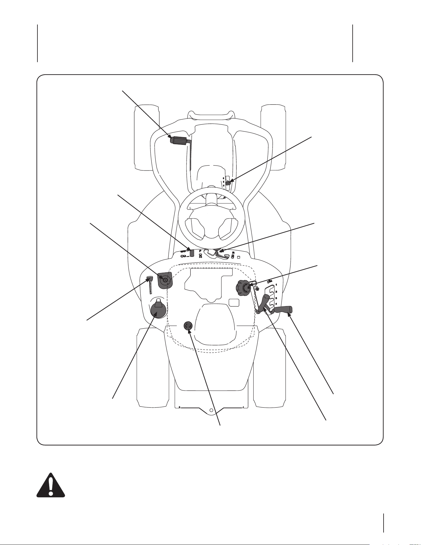
Clutch/Brake Pedal
Speed Control &
Parking Brake Lever
Shift Lever
Cup Holder
Throttle/Choke Lever
Ignition Switch Module
Deck Lift Lever
PTO (Blade Engage) Lever
Oil Fill Cap
Fuel Fill Cap
Fuel Level Indicator
Figure 4-1
Lawn Tractor controls and features are illustrated in Figure 4-1 and described on the following pages.
WARNING! Read and follow all safety rules and instructions in this manual, including the entire Operation section,
before attempting to operate this machine. Failure to comply with all safety rules and instructions may result in personal
injury.
Throttle / Choke Control
The throttle control lever is located on the left fender of the
tractor seated in the operator’s position, see Figure 4-1. This lever
controls the speed of the engine, as well as the choke when it
is pushed all the way forward. When set in a given position, the
throttle will maintain a uniform engine speed.
IMPORTANT: When operating the tractor with the cutting deck
engaged, be certain that the throttle lever is always in the FAST
(rabbit) position.
Moving the throttle lever all the way forward activates the
engine’s choke control. See Figure 4-2. Activating the choke
control closes the choke plate on the carburetor and aids in
starting the engine.
FAST
SL OW
Figure 4-2
Refer to Starting The Engine in the Operation section of this
manual for detailed starting instructions.
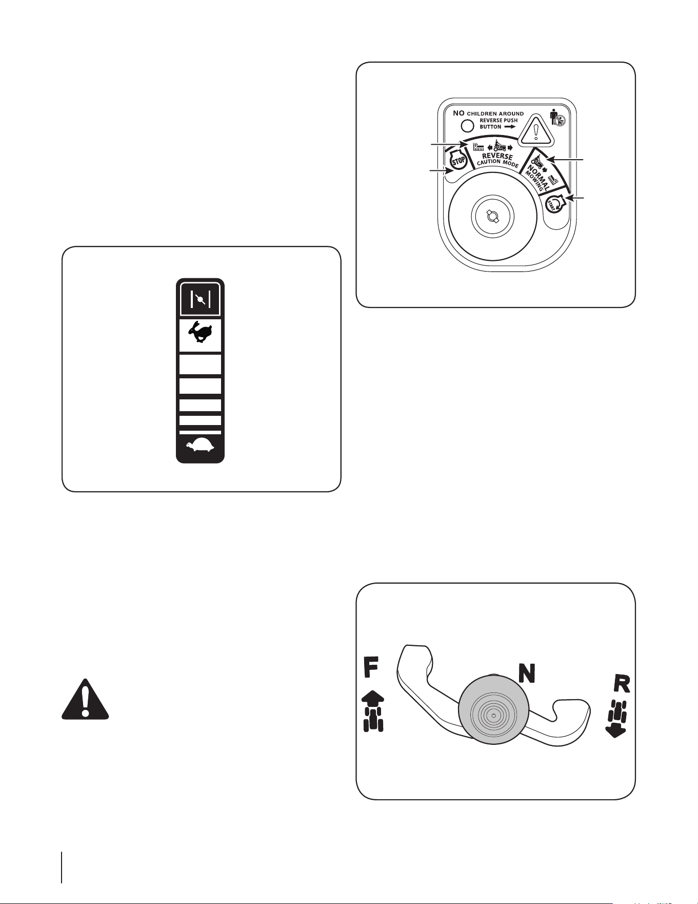
Ignition Switch Module
The ignition switch module is located on the left fender of the
tractor seated in the operator’s position, adjacent to the Throttle/
Choke Control. To start the engine, insert the key into the ignition
switch module and turn clockwise to the START position. Release
the key into the NORMAL MOWING MODE position once the
engine has fired.
To stop the engine, turn the ignition key counterclockwise to the
OFF position. See Figure 4-3.
WARNING! Never leave a running machine
unattended. Always disengage PTO, move shift lever
into neutral position, set parking brake, stop engine
and remove key to prevent unintended starting.
IMPORTANT: Prior to operating the tractor, refer to both Safety
Interlock Switches and Starting The Engine in the Operation
section of this manual for detailed instructions regarding the
Ignition Switch Module and operating the tractor in REVERSE
CAUTION MODE.
Stop Position
Reverse
C
aution Mode
Normal
Mowing
Start
Position
Figure 4-3
Clutch-Brake Pedal
The clutch-brake pedal is located on the left side of the lawn
tractor, along the running board. Depress the clutch-brake pedal
part way down when slowing the tractor by changing speeds
(Refer to Speed Control Lever). Depress the pedal all the way down
to engage the disc brake and bring the tractor to a complete stop.
NOTE: The clutch-brake pedal must be completely depressed
to start the engine. Refer to Safety Interlock Switches in the
Operation section of this manual.
Shift Lever
The shift lever is located on the control panel just below the seat,
in the center of the tractor. It has three positions, FORWARD,
NEUTRAL and REVERSE. The brake pedal must be completely
depressed and the tractor must not be in motion when moving
the shift lever. See Figure 4-4.
IMPORTANT: Never force the shift lever. Doing so may result in
serious damage to the tractor’s transmission.
Figure 4-4
14 Section 4— controlS & FeatureS
Speed Control Lever
The speed control lever, located on the right side of the tractor’s
steering console, allows you to regulate the ground speed of the
lawn tractor.
To use, depress the clutch-brake pedal and move the lever out
of the parking brake notch and forward to increase the tractor’s
ground speed. When a desired speed has been reached, release
the lever into an appropriate notch to maintain that speed.
To slow the tractor’s ground speed, depress the clutch-brake
pedal and move the speed control lever rearward and release it
into a notch.
Parking Brake
To set the parking brake, fully depress the clutch-brake pedal.
Move the speed control lever all the way down and into the
parking brake position. Release the clutch-brake pedal to allow
the parking brake to engage.
To release the parking brake, depress the clutch-brake pedal and
move the speed control lever out of the parking brake position
into the desired position. Release the clutch-brake pedal.
NOTE: The parking brake must be set if the operator leaves the
seat with the engine running or the engine will automatically
shut off.
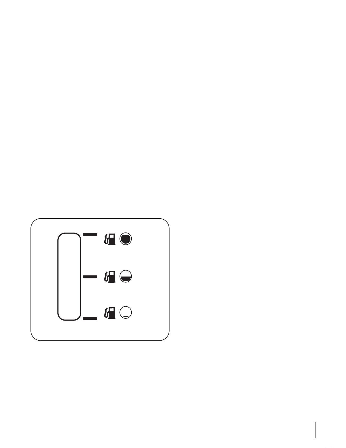
Fuel Lever Indicator
The Fuel Lever Indicator is located below the seat on the left
hand side from the operator’s position in the controls panel. Use
this window to identify the tractor’s fuel needs. See Figure 4-5.
Figure 4-5
Deck Lift Lever
Found on your tractor’s right fender, the deck lift lever is used to
change the height of the cutting deck. To use, move the lever to
the left, then place in the notch best suited for your application.
PTO (Blade Engage) Lever
Found on the tractor’s right fender, the PTO (blade engage)
lever is used to engage power to the cutting deck. To operate,
move the lever all the way forward. Moving the lever all the way
rearward into the PTO OFF position disengages power to the
cutting deck.
NOTE: The PTO (blade engage) lever must be in the disengaged
(PTO OFF) position when starting the engine.
Fuel Fill Cap
The Fuel Fill Cap is located below the seat. Refer to the Set-up
section in this manual for instructions on fueling this tractor.
Oil Fill Cap
The Oil Fill Cap is located below the seat. Refer to the Set-up
section in this manual for instructions on checking and adding
oil to this tractor.
15Section 4 — controlS & FeatureS
Operation
5
16
Operation
5
16
WARNING
Avoid Serious Injury or Death
• Knowlocationandfunctionofallcontrols.
• Removeobjectswhichcouldbethrownbytheblades.
• Goupanddownslopes,notacross.
• Useextracautiononslopes.Donotmowslopesgreater
than12degrees.Avoidsuddenturns.Uselowspeed.
• Donotoperatemachinewhereitcouldtiporslip.
• Ifmachinestopsgoinguphill,stopbladesandbackdown
slowly.
• Beforeleavingoperator’sposition,disengageblades,
engageparkingbrake,shutoffandremovekey.
• Besurebladesandenginearestoppedbeforeplacing
handsorfeetnearblades.
• Keepsafetydevices(guards,shields,switches,etc.)in
placeandworking.
• Keepbystandersaway.
• Allowmachinetocoolbeforefuelingorstoring.
• Keepmachinefreeofdebris.
Read Operator’s Manual
Safety Interlock Switches
This tractor is equipped with a safety interlock system for the
protection of the operator. If the interlock system should ever
malfunction, do not operate the tractor. Contact an authorized
MTD service dealer.
• The safety interlock system prevents the engine from
cranking or starting unless the parking brake is engaged,
and the PTO (Blade Engage) lever is in the disengaged (OFF)
position.
• The engine will automatically shut off if the operator leaves
or swivels (if equipped) the seat before engaging the
parking brake.
• The engine will automatically shut off if the operator leaves
the tractor’s seat with the PTO (Blade Engage) lever in the
engaged (ON) position, regardless of whether the parking
brake is engaged.
• The engine will automatically shut off if the PTO (Blade
Engage) lever is moved into the engaged (ON) position with
the shift lever in Reverse.
WARNING! Do not operate the tractor if the
interlock system is malfunctioning. This system was
designed for your safety and protection.
Swivel Seat
This unit is equipped with a swivel seat feature, which aids the
operator in mounting and dismounting the unit.
Note: The seat must be facing forward in the operating position
for the unit to start.
To operate the swivel seat:
1. If the seat is facing forward, lift up on the seat lever on
the left hand side of the seat and pivot the seat to the left.
Release the seat lever. See Fig. 5-1.
Figure 5-1
2. Sit in the seat, lift the seat lever and swivel the seat to the
right into the operating position.
3. Release the seat lever.
Note: See Attaching the Seat in the Assembly & Set-Up
section of this manual for instructions on adjusting the
position of the seat.
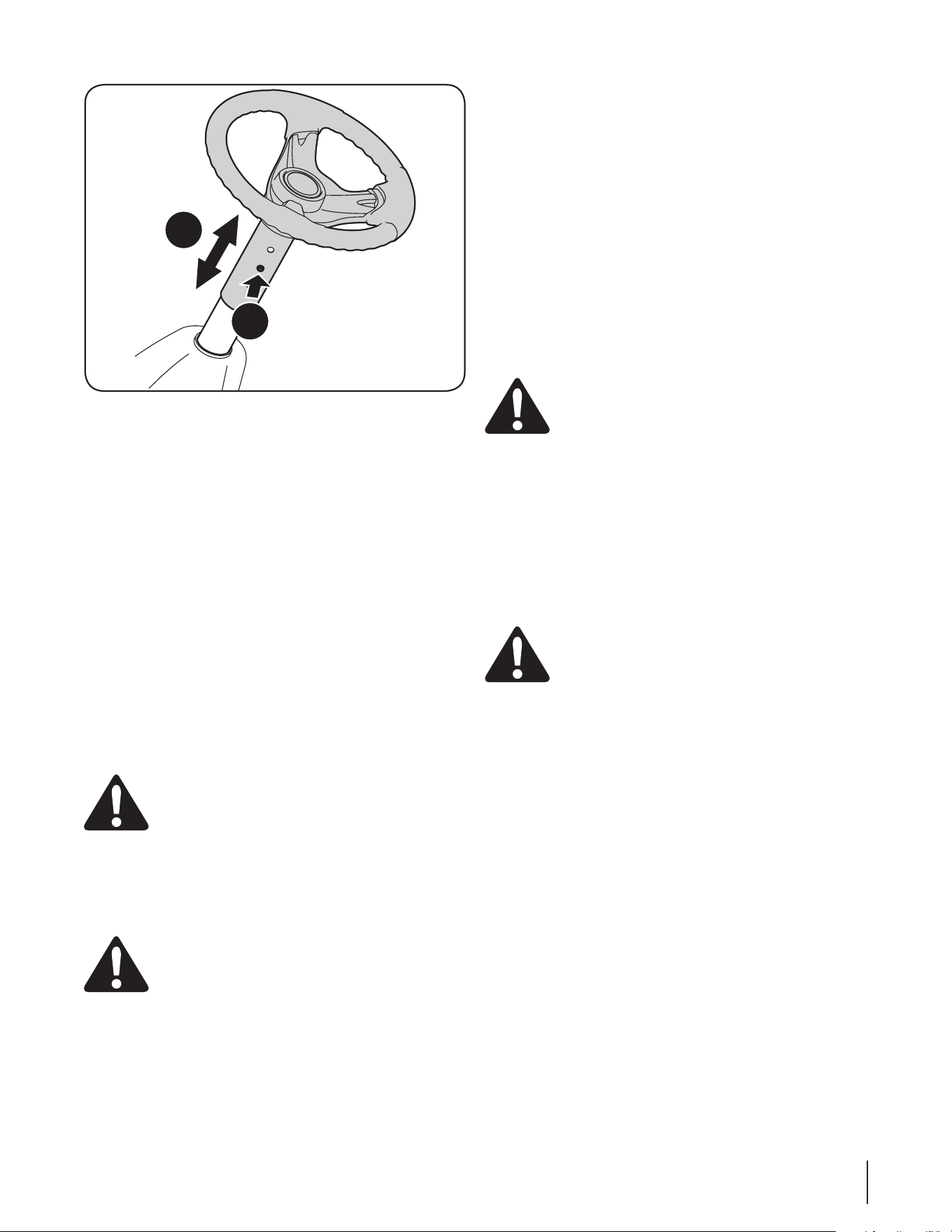
Steering Wheel Height Adjustment (if equipped)
If equipped, this unit has a telescoping steering column. To
adjust the height of the steering wheel:
1. Sit in the operator’s seat and place your hands on the
steering wheel.
2. Push the button (a) on the steering column and raise or
lower the steering wheel (b) to the desired position. See
Figure 5-2.
NOTE: Once the desired position is achieved, lift up and
down on the steering wheel to make sure it locks into
place and the button (a) on the steering column releases
into a locked position. Do not operate this unit unless the
steering column is in a locked position.
17Section 5 — operation 17Section 5 — operation
a
b
Figure 5-2
Engaging the Parking Brake
To engage the parking brake:
1. Fully depress the brake pedal and hold it down with your
foot.
2. Move the speed control lever down into the parking brake
position.
3. Release the brake pedal to allow the parking brake to
engage.
To release the parking brake:
1. Depress the brake pedal and move the speed control lever
out of the parking brake position.
Setting the Cutting Height
1. Select the height position of the cutting deck by placing
the deck lift lever in any of the different cutting height
notches on the right side of the fender.
WARNING! Keep hands and feet away from the
discharge opening of the cutting deck.
Refer to Leveling the Deck in the Maintenance & Adjustments
section of this manual for more detailed instructions regarding
various deck adjustments.
Starting the Engine
WARNING! Do not operate the tractor if the
interlock system is malfunctioning. This system was
designed for your safety and protection.
NOTE: Refer to the Assembly & Set-Up section of this manual for
gasoline and oil fill-up instructions.
1. Insert the tractor key into the ignition switch.
2. Place the PTO (Blade Engage) lever in the disengaged (OFF)
position.
3. Engage the tractor’s parking brake.
4. Activate the choke control.
5. Turn the ignition key clockwise to the START position. After
the engine starts, release the key. It will return to the ON
position.
IMPORTANT: Do NOT hold the key in the START position
for longer than ten seconds at a time. Doing so may cause
damage to your engine’s electric starter.
6. After the engine starts, deactivate the choke control by
placing the throttle control into the FAST position.
NOTE: Do NOT operate this unit with the Choke control
activated. Doing so will result in a “rich” fuel mixture and can
cause the engine to run poorly.
Stopping the Engine
WARNING! If you strike a foreign object, stop the
engine, disconnect the spark plug wire and ground
against the engine. Thoroughly inspect the machine
for any damage. Repair the damage before
restarting and operating.
1. If the blades are engaged, place the PTO (Blade Engage)
lever in the disengaged (OFF) position.
2. Turn the ignition key counterclockwise to the STOP
position.
3. Remove the key from the ignition switch to prevent
unintended starting.
Driving The Tractor
WARNING! Avoid sudden starts, excessive speed
and sudden stops.
WARNING! Do not leave the seat of the tractor
without first placing the PTO (Blade Engage) lever in
the disengaged (OFF) position, depressing the brake
pedal and engaging the parking brake. If leaving
the tractor unattended, also turn the ignition key off
and remove the key.
WARNING! Always look down and behind before
and while backing up to avoid a back-over accident.
1. Move the throttle lever into the FAST (rabbit) position.
2. Place the shift lever in either the FORWARD or REVERSE
position.
3. Depress the clutch-brake pedal and move the speed
control lever out of the parking brake position into desired
speed position.
IMPORTANT: Do NOT use the shift lever to change the
direction of travel when the tractor is in motion. Always use
the brake pedal to bring the tractor to a complete stop before
shifting.
IMPORTANT: First-time operators should use speed positions 1
or 2. Become completely familiar with the tractor’s operation and
controls before operating the tractor in higher speed positions.
4. Release clutch-brake pedal slowly to put unit into motion.
5. The lawn tractor is brought to a stop by depressing the
clutch-brake pedal.
18 Section 5— operation18 Section 5— operation
NOTE: When operating the unit initially, there will be little
difference between the highest two speeds until after the belts
have seated themselves into the pulleys during the break-in
period.
WARNING! Before leaving the operator’s position
for any reason, disengage the blades, place the shift
lever in neutral, engage the parking brake, shut
engine off and remove the key.
IMPORTANT: When stopping the tractor for any reason while
on a grass surface, always:
1. Place the shift lever into neutral.
2. Engage the parking brake,
3. Shut the engine off and remove the key. Doing so will
minimize the possibility of having your lawn ‘‘browned’’ by
hot exhaust from your tractor’s running engine.
If unit stalls with speed control in high speed, or if unit will
not operate with speed control lever in a low speed position,
proceed as follows:
1. Place shift lever in NEUTRAL.
2. Restart engine.
3. Place speed control lever in highest speed position.
4. Release clutch-brake pedal fully.
5. Depress clutch-brake pedal.
6. Place speed control lever in desired position.
7. Place shift lever in either FORWARD or REVERSE, and follow
normal operating procedures.
Driving On Slopes
Refer to the SLOPE GAUGE in the Important Safe Operation
Practices section in the front of this manual to help determine
slopes where you may operate the tractor safely.
WARNING! Do not mow on inclines with a slope in
excess of 12 degrees (a rise of approximately 2 feet for
every 10 feet). The tractor could overturn and cause
serious injury.
• Mow up and down slopes, NEVER across.
• Exercise extreme caution when changing direction on
slopes.
• Watch for holes, ruts, bumps, rocks, or other hidden
objects. Uneven terrain could overturn the machine. Tall
grass can hide obstacles.
• Avoid turns when driving on a slope. If a turn must be
made, turn down the slope. Turning up a slope greatly
increases the chance of a roll over.
• Avoid stopping when driving up a slope. If it is necessary
to stop while driving up a slope, start up smoothly and
carefully to reduce the possibility of flipping the tractor
over backward.
Engaging the Blades
Engaging the PTO (Blade Engage) transfers power to the cutting
deck. To engage the blades, proceed as follows:
1. Move the throttle control lever to the FAST (rabbit)
position.
2. Grasp the PTO (Blade Engage) lever and pivot it all the way
forward into the engaged (ON) position.
3. Keep the throttle lever in the FAST (rabbit) position for the
most efficient use of the cutting deck.
IMPORTANT: The PTO (Blade Engage) lever must be in the
disengaged (OFF) position when starting the engine, when
traveling in reverse, and if the operator leaves the seat. Refer to
Safety Interlock Switches in the Operation section of this manual.
Mulching
A mulch kit is available as an attachment. Mulching is a process
of recirculating grass clippings repeatedly beneath the cutting
deck. The ultra-fine clippings are then forced back into the
lawn where they act as a natural fertilizer. A mulch kit can be
purchased. See the Attachments & Accessories section in this
manual for more information on purchasing a mulch kit.
Using the Deck Lift Lever
To raise the cutting deck, move the deck lift lever to the left, then
place it in the notch best suited for your application. Refer to
Setting The Cutting Height earlier in this section.
Mowing
WARNING! To help avoid blade contact or a
thrown object injury, keep bystanders, helpers,
children and pets at least 75 feet from the machine
while it is in operation. Stop machine if anyone
enters the area.
The following information will be helpful when using the cutting
deck with your tractor:
WARNING! Plan your mowing pattern to avoid
discharge of materials toward roads, sidewalks,
bystanders and the like. Also, avoid discharging
material against a wall or obstruction which may
cause discharged material to ricochet back toward
the operator.
• Do not mow at high ground speed, especially if a mulch kit
or grass collector is installed.
• For best results it is recommended that the first two laps be
cut with the discharge thrown towards the center. After the
first two laps, reverse the direction to throw the discharge
to the outside for the balance of cutting. This will give a
better appearance to the lawn.
• Do not cut the grass too short. Short grass invites weed
growth and yellows quickly in dry weather.
• Mowing should always be done with the engine at full
throttle.
• Under heavier conditions it may be necessary to go back
over the cut area a second time to get a clean cut.
• Do NOT attempt to mow heavy brush and weeds and
extremely tall grass. Your tractor is designed to mow lawns,
NOT clear brush.
• Keep the blades sharp and replace the blades when worn.
Refer to Cutting Blades in the Service section of this manual
for proper blade sharpening instructions.
Maintenance
WARNING: Before performing any maintenance or
repairs, disengage PTO, move shift lever into neutral
position, set parking brake, stop engine and remove
key to prevent unintended starting.
Engine
Refer to the Engine Owner’s Manual for engine maintenance
instructions.
Check engine oil level before each use as instructed in the Engine
Owner’s Manual packed with your unit. Follow the instructions
carefully.
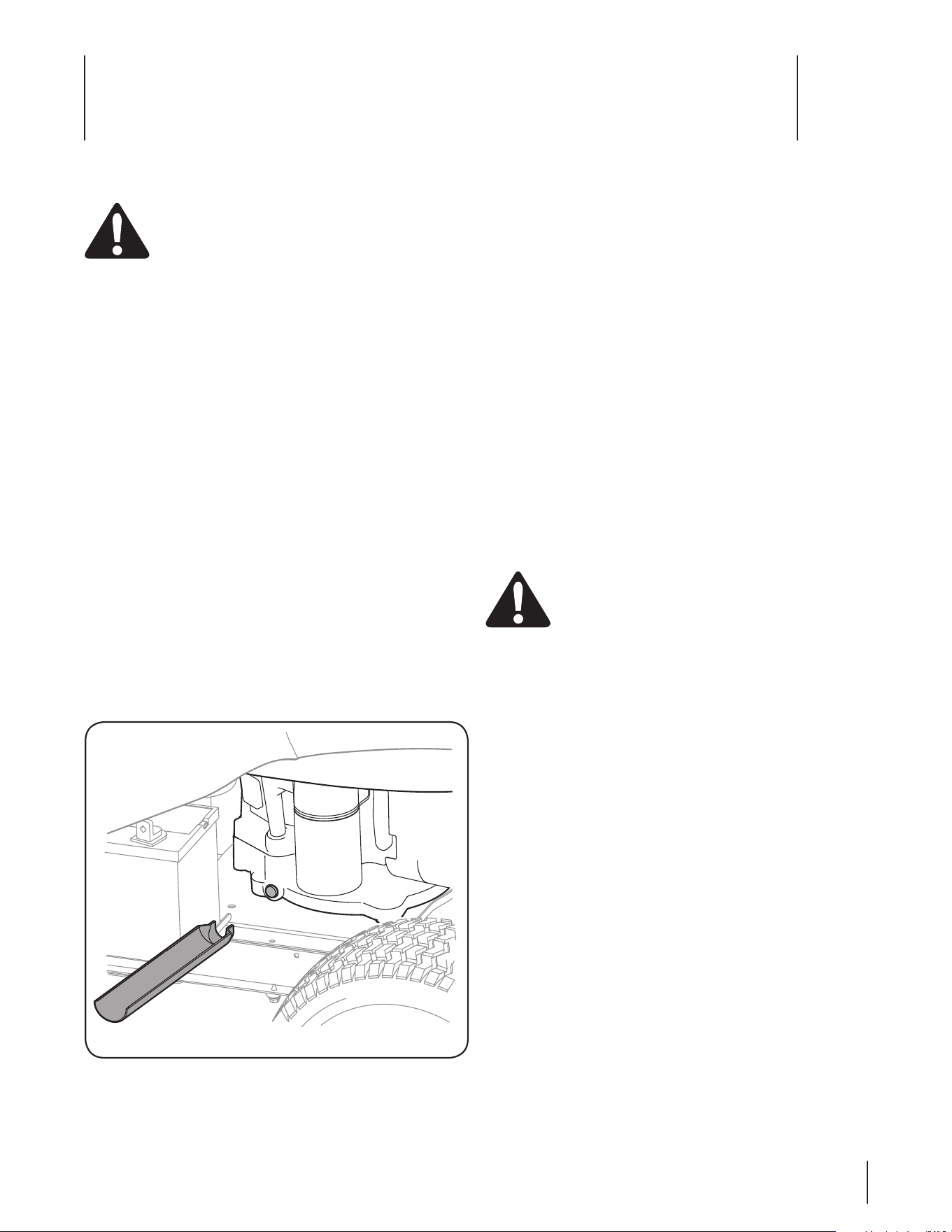
Changing Engine Oil
For draining oil from the engine’s crankcase, proceed as follows:
1. Run the engine for a few minutes to allow the oil in the
crankcase to warm up. Warm oil will flow more freely and
carry away more of the engine sediment which may have
settled at the bottom of the crankcase. Use care to avoid
burns from hot oil.
2. Locate the oil drain port on the right side of the engine and
the oil fill cap on the topside of the engine.
3. Unscrew the oil fill cap and remove the dipstick from the oil
fill tube.
4. Snap the small end of oil drain sleeve onto the engine
casting around the oil drain plug. See Fig. 6-1.
Note: Tip the unit slightly in the direction of the suitable
container to aid in fully draining all of the oil form the
engine.
Figure 6-1
5. Remove drain plug and drain oil into a suitable container
with a capacity of no less than 64 oz.
6. Reinstall the oil drain plug securely. Be careful not to
overtighten.
7. Refill the engine with new motor oil as instructed in the
Engine Owner’s Manual packed with your unit.
IMPORTANT: Refer to the Engine Owner’s Manual packed with
your unit for information regarding the quantity and proper
viscosity of motor oil.
Air Cleaner
Service the air cleaner element as instructed in the Engine
Owner’s Manual packed with your unit.
Spark Plug
The spark plug should be cleaned and the gap reset once
a season. Spark plug replacement is recommended at the
start of each mowing season. Refer to the Engine Owner’s
Manual packed with your unit for correct plug type and gap
specifications.
Lubrication
WARNING: Before lubricating, repairing, or
inspecting, always disengage PTO, move shift lever
into neutral position, set parking brake, stop engine
and remove key to prevent unintended starting.
Engine
Lubricate the engine with motor oil as instructed in the Engine
Owner Manual packed with your unit.
Pivot Points & Linkage
Lubricate all the pivot points on the drive system, parking brake
and lift linkage at least once a season with light oil.
Maintenance & Adjustments
6
19
Inspect muffler periodically, and replace if necessary.
Replacement parts for the muffler must be the same and
installed in the same position as the original parts.
Battery
The battery is sealed and is maintenance-free. Acid levels cannot
be checked.
• Always keep the battery cables and terminals clean and
free of corrosive build-up.
• After cleaning the battery and terminals, apply a light coat
of petroleum jelly or grease to both terminals.
• Always keep the rubber boot positioned over the positive
terminal to prevent shorting.
IMPORTANT: If removing the battery for any reason,
disconnect the NEGATIVE (Black) wire from it’s terminal first,
followed by the POSITIVE (Red) wire. When re-installing the
battery, always connect the POSITIVE (Red) wire its terminal
first, followed by the NEGATIVE (Black) wire. Be certain that the
wires are connected to the correct terminals; reversing them
could change the polarity and result in damage to your engine’s
alternating system.
Cleaning Battery
Clean the battery by removing it from the tractor and washing
with a baking soda and water solution. If necessary, scrape the
battery terminals with a wire brush to remove deposits. Coat
terminals and exposed wiring with grease or petroleum jelly to
prevent corrosion.
Adjustments
WARNING: Never attempt to make any
adjustments while the engine is running, except
where specified in the operator’s manual.
Seat Adjustment
Refer to the Set-Up and Assembly section of this manual for seat
adjustment instructions.
Parking Brake Adjustment
WARNING: Never attempt to adjust the brakes
while the engine is running. Always disengage PTO,
move shift lever into neutral position, stop engine
and remove key to prevent unintended starting.
If the tractor does not come to a complete stop when the brake
pedal is completely depressed, or if the tractor’s rear wheels
can roll with the parking brake applied, the brake is in need of
adjustment. See an authorized Troy-bilt Service Dealer to have
your brakes properly adjusted.
Rear Wheels
The rear wheels should be removed from the axles once a
season. Lubricate the axles and the rims well with an all-purpose
grease before re-installing them.
Steering Rack & Pinion
Once per season, or every 25 hours of operation, it will be
necessary to lubricate the steering rack and pinion gear located
under the front of the unit. Using standard automotive grease,
apply grease to the front side and rear side of the steering rack,
as indicated in Figure 6-2.
Figure 6-2
Cleaning the Engine And Deck
If the engine has been running, allow it to cool for at least half
an hour before cleaning. Periodically remove dirt build-up from
engine. Clean cooling fins every 25 hours. Clean with a brush or
compressed air.
IMPORTANT: Do not spray engine with water to clean because
water could contaminate fuel. Using a garden hose or pressure
washing equipment can also force water into the air cleaner or
muffler opening. Water in the air cleaner will soak the paper
element, and water that passes through the element or muffler
can enter the cylinder, causing damage.
Any fuel or oil spilled on the machine should be wiped off
promptly. Do NOT allow debris to accumulate around the cooling
fins of the engine or on any other part of the machine.
IMPORTANT: The use of a pressure washer to clean your
tractor is NOT recommended. It may cause damage to electrical
components, spindles, pulleys, bearings or the engine.
WARNING! Accumulation of debris around muffler
could cause a fire. Inspect and clean before every
use.
Muffler
WARNING! Temperature of muffler and nearby
engine areas may exceed 150˚ F (65˚C). Avoid
contact with these areas.
20 Section 6— Maintenance & adjuStMentS
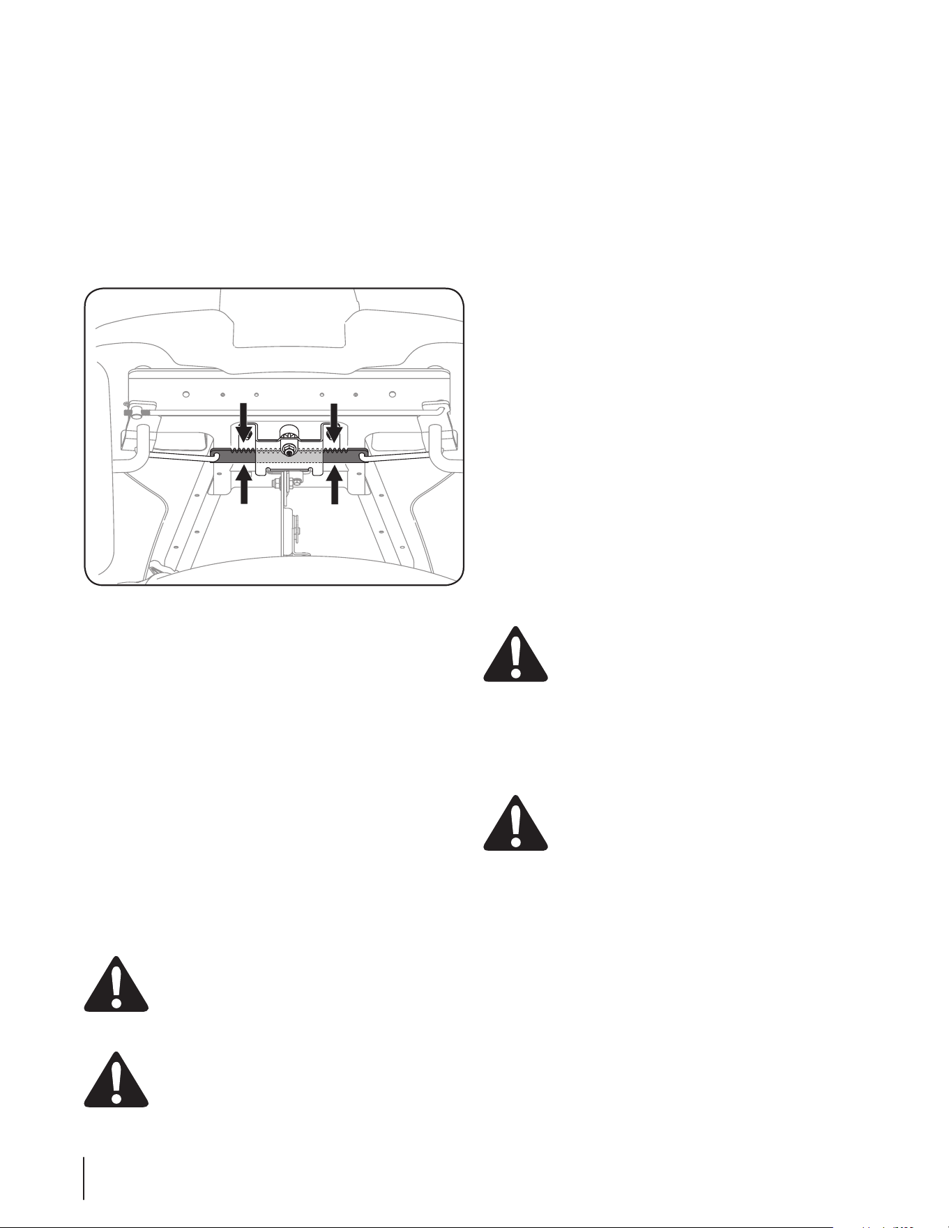
Leveling the Deck
NOTE: Check the tractor’s tire pressure before performing any
deck leveling adjustments. Refer to Tires, later in this section of
this manual for more information regarding tire pressure.
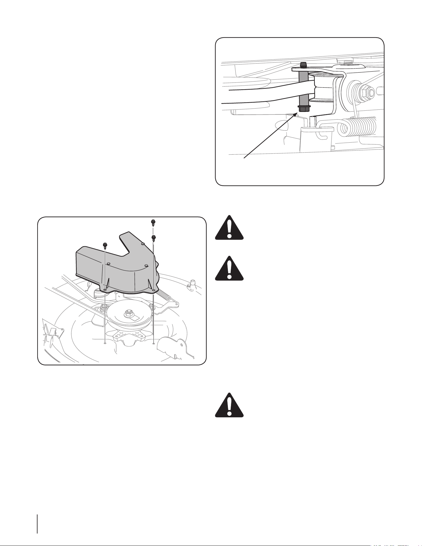
Front To Rear
It is possible to adjust the pitch of the cutting deck. The front of
the deck should be between 0” (level) and 1⁄4” lower than the
rear of the deck. Adjust if necessary as follows:
1. With the tractor parked on a firm, level surface, place the lever
for lifting the platform in the middle position and rotate
the blade so that it is aligned with the front and rear of the
tractor.
2. Measure the distance from the front of the blade tip to the
ground and the rear of the blade tip to the ground. The
first measurement taken should be between 0” (level) and
1⁄4” less than the second measurement. Determine the
approximate distance necessary for proper adjustment and
proceed, if necessary, to the next step.
3. Locate the flange lock nut on the front end of the PTO Lift Rod.
See Figure 6-3.
• Tighten the flange lock nut to raise the front of the deck;
• Loosen the flange lock nut to lower the front of the deck.
Figure 6-3
Tires
WARNING! Never exceed the maximum inflation
pressure shown on the sidewall of the tire.
The recommended operating tire pressure is:
• Approximately 14 psi for the rear tires
• Approximately 20 psi for the front tires
IMPORTANT: Refer to the tire sidewall for exact tire
manufacturer’s recommended or maximum psi. Do not
overinflate. Uneven tire pressure could cause the cutting deck to
mow unevenly.
Off Season Storage
WARNING! Never store lawn tractor with fuel in
tank indoors or in poorly ventilated areas where fuel
fumes may reach an open flame, spark, or pilot light
as on a furnace, water heater, clothes dryer, or gas
appliance.
Preparing the Engine
IMPORTANT: Fuel left in the fuel tank during warm weather
deteriorates and will cause serious starting problems.
To prevent gum deposits from forming inside the engine’s
carburetor and causing possible malfunction of the engine, the
fuel system must be either completely emptied, or the gasoline
must be treated with a stabilizer to prevent deterioration.
1. If using a fuel stabilizer:
• Read the product manufacturer’s instructions and
recommendations.
• Add to clean, fresh gasoline the correct amount of stabilizer
for the capacity of the fuel system.
• Fill the fuel tank with treated fuel and run the engine for
2-3 minutes to get stabilized fuel into the carburetor.
2. If emptying the fuel system:
• Do not drain fuel when the engine is hot. Allow the
engine adequate time to cool. Drain fuel into an approved
container outdoors, away from open flame.
• Drain any large volume of fuel from the tank by
disconnecting the fuel line from the in-line fuel filter near
the engine. See the complete instructions for Draining The
Fuel later in this section.
WARNING! Gasoline is extremely flammable and
can be explosive under certain conditions. Drain
gasoline before storing the equipment for extended
periods. Drain fuel only into an approved container
outdoors, away from an open flame. Allow engine to
cool. Extinguish cigarettes, cigars, pipes, and other
sources of ignition prior to draining fuel. Store
gasoline in an approved container in safe location.
• Reconnect the fuel line and run the engine until it starts to
falter, then use the choke to keep the engine running until
all fuel in the carburetor has been exhausted.
• Disconnect the fuel line and drain any remaining gasoline
from the system.
WARNING! Gasoline is a toxic substance. Dispose
of gasoline properly. Contact your local authorities
for approved disposal methods.
• Remove the spark plug and pour one (1) ounce of engine
oil through the spark plug hole into the cylinder. Crank the
engine several times to distribute the oil. Replace the spark
plug.
21Section 6 — Maintenance & adjuStMentS

Draining the fuel
1. Locate the fuel filter, which is located on the left side of the
engine, and may be attached to the engine with a tie strap.
2. Cut the tie strap, if present, then pinch the in-line clamp
on the fuel filter with a pair of pliers, slide the clamp up the
fuel line.
3. Pull the fuel line free from the filter and place the open end
of the line into an approved container to drain the fuel.
Preparing the Lawn Tractor
1. Clean and lubricate tractor thoroughly as described in the
lubrication instructions.
2. Do not use a pressure washer or garden hose to clean your
unit.
3. Store mower in a dry, clean area. Do not store next to
corrosive materials, such as fertilizer.
Maintenance Schedule
Before
Each use
Every
10 Hours
Every
25 Hours
Every
50 Hours
Every
100 Hours
Prior
to Storing
Check Engine Oil Level
P P
Check Air Filter for Dirty, Loose or Damaged Parts
P
Clean and Re-oil Air Filter’s Foam Pre-cleaner
(if Equipped)
P
Replace Air Filter Element
P
Change Engine Oil and Replace Oil Filter
(if Equipped)
P
Clean Battery Terminals
P P
Lube Front Axles and Rims
P P
Clean Engine Cooling Fins
P P
Check Spark Plug Condition & Gap
P P
Replace Fuel Filter
P
IMPORTANT: It is important to consult the specific engine operator’s manual included with this machine for detailed engine
maintenance procedures and intervals.
22 Section 6— Maintenance & adjuStMentS
Se rvice
7
23
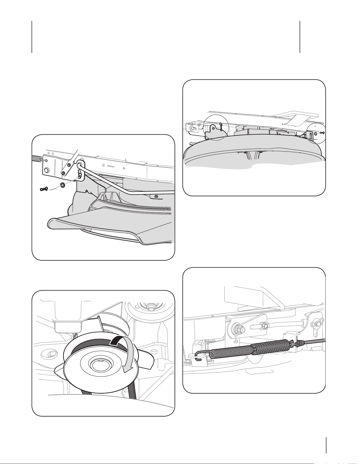
5. Remove the remaining bow-tie cotter pins securing the
deck to the unit, as shown in Figure 7-3 .
Figure 7-3
NOTE: The bow-tie clips should be re-installed from the top
down.
6. Unplug the wire pigtail from the deck switch.
7. Move the deck lift lever into the top notch on the right
fender to raise the deck lift arms up and out of the way.
8. Carefully remove the PTO cable from the rear of the cutting
deck. Remove the spring from the deck idler bracket. See
Figure 7-4.
Figure 7-4
9. Gently slide the cutting deck (from the left side) out from
underneath the tractor.
Cutting Deck Removal
To remove the cutting deck, proceed as follows:
1. Place the PTO (Blade Engage) lever in the disengaged (OFF)
position and engage the parking brake.
2. Lower the deck by moving the deck lift lever into the
bottom notch on the right fender.
3. Remove the bow-tie cotter pin and flat washer from the
deck lift assembly, and retain for reinstallation later. See
Figure 7-1.
Figure 7-1
4. Remove the belt from around the tractor’s PTO pulley. See
Figure 7-2 .
Figure 7-2
24 Section 7— Service
Changing the Deck Belt
NOTE: It is possible to change the deck belt with the cutting
deck still installed on the tractor, however it is much easier to
remove the deck first, change the deck belt, then reinstall the
cutting deck.
To change the cutting deck belt, proceed as follows:
1. It is easiest to change the deck belt by first removing the
cutting deck as instructed earlier in this section.
2. If changing the deck belt with the cutting deck still
installed on the unit, lower the deck to the lowest mowing
position.
3. Remove the deck belt from around the unit’s PTO drive
pulley as shown in Figure 7-2. Simply roll one side of the
belt off of the pulley and then work it off the pulley by
continuing around the pulley until the belt is off of the
pulley.
4. Pull the belt towards the front of the unit, pulling it through
and out of the belt keeper rod. See Figure 7-2.
5. Remove the deck belt cover by removing the three hex
bolts that secure it. See Figure 7-5.
Figure 7-5
6. Remove the belt keeper by removing the hex bolt that
secures it. See Figure 7-6.
7. Change the belt then reinstall all the components removed
in the reverse order beginning with the idler pulley, and
then belt cover.
8. Feed the deck belt through the belt keeper rod and work
it around and onto the PTO drive pulley as shown in Figure
7-2.
Belt Keeper Hex bolt
Figure 7-6
Battery
CALIFORNIA PROPOSITION 65 WARNING!
Battery posts, terminals, and related accessories
contain lead and lead compounds, chemicals known
to the State of California to cause cancer and
reproductive harm. Wash hands after handling.
CAUTION: If removing the battery, disconnect the
NEGATIVE (Black) wire from it’s terminal first,
followed by the POSITIVE (Red) wire. When re-
installing the battery, always connect the POSITIVE
(Red) wire its terminal first, followed by the
NEGATIVE (Black) wire.
Battery Failures
Some common causes for battery failure are:
• Incorrect initial activation
• Overcharging
• Freezing
• Undercharging
• Corroded connections
These failures are NOT covered by your tractor’s warranty.
Jump Starting
WARNING! Never jump start a damaged or frozen
battery. Be certain the vehicles do not touch, and
ignitions are off. Do not allow cable clamps to touch.
1. Connect positive (+) cable to positive post (+) of your
tractor’s discharged battery.
2. Connect the other end of the cable to the (positive +) post
of the jumper battery.
3. Connect the second cable (negative –) to the other post of
the jumper battery.
4. Make the final connection on the engine block of the
tractor, away from the battery. Attach to a unpainted part
to assure a good connection.
25Section 7 — Service
CAUTION: If the jumper battery is installed on a
vehicle (i.e. car, truck), do NOT start the vehicle’s
engine when jump starting your tractor.
5. Start the tractor as instructed in the Operation section of
this manual.
6. Set the tractor’s parking brake before removing the jumper
cables, in reverse order of connection.
Charging
WARNING! Batteries give off an explosive gas
while charging. Charge the battery in a well
ventilated area and keep away from an open flame
or pilot light as on a water heater, space heater,
furnace, clothes dryer or other gas appliances.
CAUTION: When charging your tractor’s battery,
use only a charger designed for 12V lead-acid
batteries. Read your battery charger’s Owner’s
Manual prior to charging your tractor’s battery.
Always follow its instructions and heed its warnings.
If your tractor has not been put into use for an extended period
of time, charge the battery as follows:
1. Set your battery charger to deliver a max of 10 amperes.
If your battery charger is automatic, charge the battery until the
charger indicates that charging is complete. If the charger is not
automatic, charge for no fewer than eight hours.
Fuse
One 15 AMP fuse is installed in your tractor’s wiring harness
located just above the battery, under the left fender, to protect
the tractor’s electrical system from damage caused by excessive
amperage.
If the electrical system does not function, or your tractor’s engine
will not crank, first check to be certain that the fuse has not
blown. It can be found at the rear of the unit, underneath the
fender located by the battery.
WARNING! Always use a fuse with the same
amperage capacity for replacement.
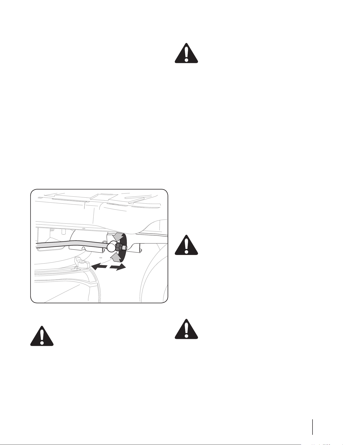
Cutting Blade
WARNING! Shut the engine off and remove
ignition key before removing the cutting blade(s) for
sharpening or replacement. Protect your hands by
using heavy gloves when grasping the blade.
WARNING! Periodically inspect the blade spindles
for cracks or damage, especially if you strike a
foreign object. Replace immediately if damaged.
The blades may be removed as follows.
NOTE: It may be easier to change the blade by first
removing the deck from beneath the tractor, (refer to
Cutting Deck Removal earlier in this section) then gently
flip the deck over to expose its underside. It is possible to
change the blade, however, with the deck still attached to
the tractor. If attempting to change the blade with the deck
still installed on the tractor, first move the deck lift lever to
its highest cutting position.
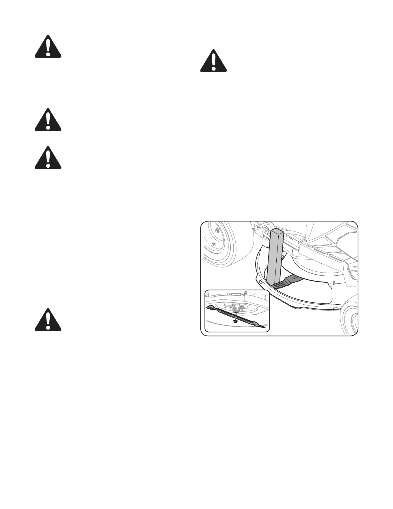
1. Remove the mulch plug, deck chute or bagging chute, if
equipped, exposing the deck chute opening.
2. Using a block of wood or 2 x 4, insert it into the deck
opening and rotate the blade around until it wedges the
wood between the deck opening and the cutting blade, as
shown in Figure 7-7.
Figure 7-7
3. Remove the hex flange nut that secures the blade to the
spindle assembly. See the Inset of Figure 7-7 .
NOTE: The deck spindle has a normal thread. To loosen,
rotate the flange lock nut counter clockwise.
26 Section 7— Service
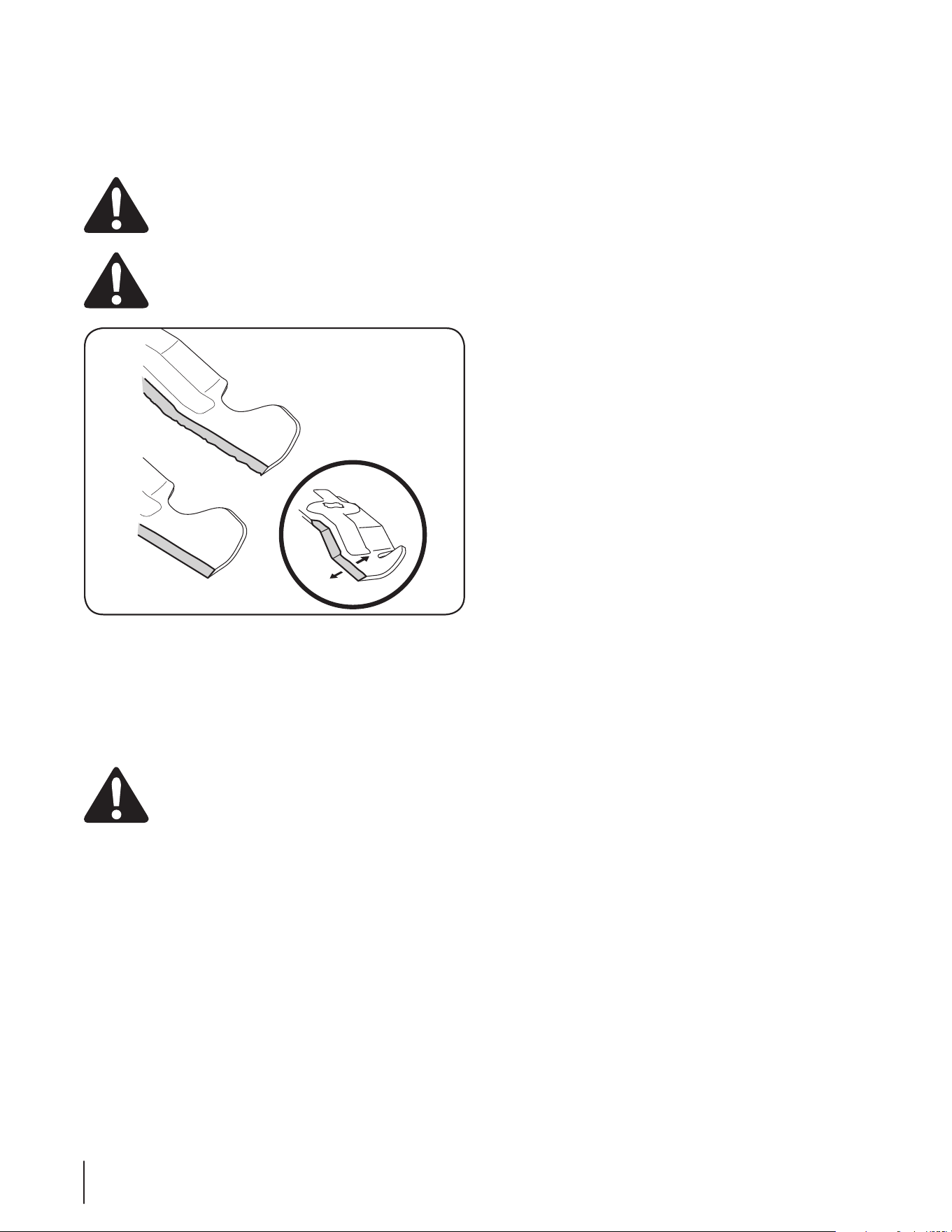
4. To properly sharpen the cutting blades, remove equal
amounts of metal from both ends of the blades along the
cutting edges, parallel to the trailing edge, at a 25°- to 30°
angle. Always grind each cutting blade edge equally to
maintain proper blade balance. See Figure 7-8.
WARNING! If the cutting edge of the blade has
previously been sharpened, or if any metal
separation is present, replace the blades with new
ones.
WARNING! A poorly balanced blade will cause
excessive vibration, may cause damage to the
tractor and/or result in personal injury.
Figure 7-8
5. Test the blade’s balance using a blade balancer. Grind
metal from the heavy side until it balances evenly.
NOTE: When replacing the blade, be sure to install the
blade with the side of the blade marked ‘‘Bottom’’ (or with
a part number stamped in it) facing the ground when the
mower is in the operating position.
CAUTION! Use a torque wrench to tighten the
blade spindle hex flange nut to between 70 lbs-ft
and 90 lbs-ft.
Changing the Transmission Drive Belt
NOTE: Several components must be removed and special tools
(i.e. air/impact wrench) in order to change the tractor’s drive
belt. See an authorized Service Dealer to have your drive belt
replaced or phone Customer Support as instructed on page 2 for
information on ordering a Service Manual.

Problem Cause Remedy
Engine fails to start 1. PTO/Blade engaged
2. Spark plug wire disconnected
3. Fuel tank empty, or stale fuel
4. Choke not activated
5. Faulty spark plug
6. Blown fuse
7. Engine flooded
8. Parking brake not engaged
9. Deck chute, mulch plug or chute tube not
poperly installed.
1. Place blade engage lever in disengaged
(OFF) position.
2. Connect wire to spark plug.
3. Fill tank with clean, fresh (less than 30 days
old) gas.
4. Place the throttle control in CHOKE position.
5. Clean, adjust gap or replace plug.
6. Replace fuse(s)
7. Crank engine with throttle in FAST position.
8. Engage parking brake.
9. Check the installation of the deck chute,
mulch plug or chute tube.
Engine runs erratic 1. Unit running with CHOKE activated.
2. Spark plug wires loose.
3. Blocked fuel line or stale fuel.
4. Vent in gas cap plugged.
5. Water or dirt in fuel system.
6. Dirty air cleaner.
1. Move the throttle contol out of the CHOKE
position.
2. Connect and tighten spark plug wire.
3. Clean fuel line; fill tank with clean, fresh
gasoline and replace fuel filter
4. Clear vent or replace cap if damaged.
5. Drain fuel tank. Refill with clean, fresh
gasoline.
6. Replace air cleaner paper element or clean
foam precleaner.
Engine overheats 1. Engine oil level low.
2. Air flow restricted.
1. Fill crankcase with proper amount and
weight of oil.
2. Clean grass clippings and debris from around
the engine’s cooling fins and blower housing.
Engine hesitates at high
RPM
1. Spark plug gap too close. 1. Remove spark plug and reset the gap.
Engine Idles rough 1. Spark plug fouled, faulty or gap too wide.
2. Dirty air cleaner.
1. Replace spark plug. Set plug gap.
2. Replace air cleaner element and/or clean
pre-cleaner.
Excessive vibration 1. Cutting blade loose or unbalanced.
2. Damaged or bent cutting blade.
1. Tighten blade and spindle. Balance blade.
2. Replace blade.
Mower will not mulch grass 1. Engine speed too low.
2. Wet grass.
3. Excessively high grass.
4. Dull blade.
1. Place throttle in FAST (rabbit) position.
2. Do not mulch when grass is wet.
3. Mow once at a high cutting height, then
mow again at desired height or make a
narrower cutting swath.
4. Sharpen or replace blade.
Uneven cut 1. Deck not leveled properly.
2. Dull blade.
3. Uneven tire pressure.
1. Perform side-to-side deck adjustment.
2. Sharpen or replace blade.
3. Check tire pressure in all four tires.
Troubleshooting
8
27
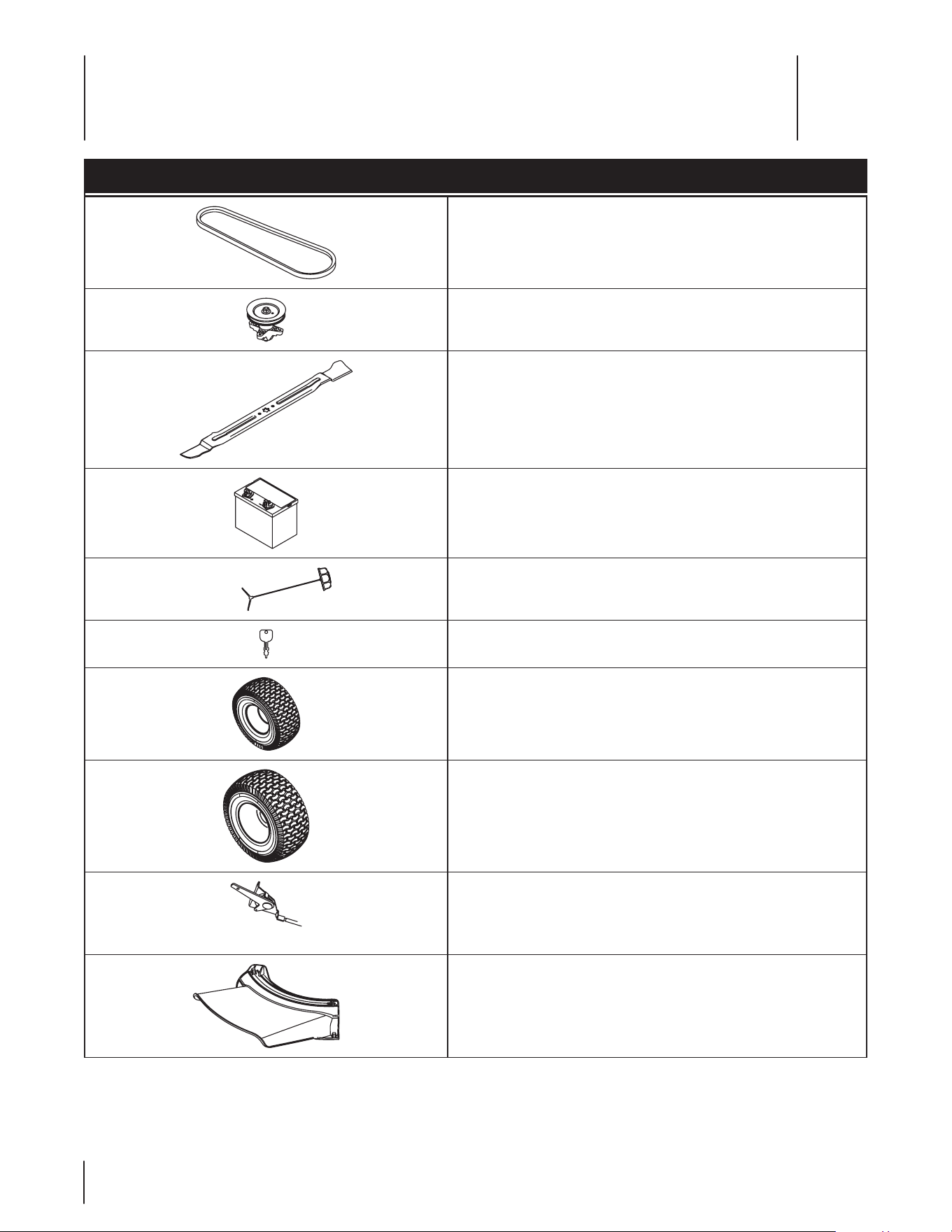
Component Part Number and Description
954-05001 Drive Belt (Mowing Deck)
918-04822A Deck Spindle
942-04385 Cutting Blade (30”)
925-1707D Battery
751-12179A Fuel Tank Cap
925-1745A Key
634-04732 Front Wheel Ass’y Complete 13 x 5 x 6
734-0298-0901 Tire Only (Front) 13 x 5 x 6
634-04732 Rear Wheel Ass’y Complete 16 x 6.5 x 8
734-04641 Tire (Rear) 16 x 6.5 x 8
746-04829A Throttle Control/Cable
731-09357 Discharge Chute Assembly
NOTE: Download a complete Parts Manual free of charge at www.mtdproducts.com or phone (800) 668-1238 to purchase a Parts
Manual. Be sure to have your model number and serial number ready. These can be found on the model plate located under the seat.
Refer to page 2 for more information regarding locating your model and serial numbers.
Replacement Parts
9
28

ThefollowingattachmentsandaccessoriesarecompatibleforMini-RiderLawnTractors.Seetheretailerfromwhichyoupurchasedyour
tractor,anauthorizedMTDServiceDealerorphone(800)800-7310forinformationregardingpriceandavailability.
CAUTION: TheMini-RiderLawnTractorsareNOTdesignedforusewithanytypeofground-engagingattachments(e.g.tiller
orplow).UseofthistypeofequipmentWILLvoidthetractor’swarranty.
Model Number Description
19A30 011O EM Twin Bagger Kit
19A30012OEM Deck Mulch Kit
Attachments & Accessories
10
29

30
FEDERAL and/or CALIFORNIA EMISSION CONTROL WARRANTY STATEMENT
YOUR WARRANTY RIGHTS AND OBLIGATIONS
MTD Consumer Group Inc, the United States Environmental Protection Agency (EPA), and, for those products certified for sale in the
state of California, the California Air Resources Board (CARB) are pleased to explain the emission (evaporative and/or exhaust) control
system (ECS) warranty on your outdoor 2006 and later small off-road spark-ignited engine and equipment (outdoor equipment
engine) In California, new outdoor equipment engines must be designed, built and equipped to meet the State’s stringent anti-smog
standards (in other states, 1997 and later model year equipment must be designed, built, and equipped to meet the U.S. EPA small
off-road, spark ignition engine regulations. MTD Consumer Group Inc must warrant the ECS on your outdoor equipment engine for
the period of time listed below provided there has been no abuse, neglect or improper maintenance of outdoor equipment engine.
Your ECS may include parts such as the carburetor, fuel-injection system, the ignition system, catalytic converter, fuel tanks, fuel lines,
fuel caps, valves, canisters, filters, vapor hoses, clamps, connectors, and other associated emission-related components.
Where a warrantable condition exists, MTD Consumer Group Inc will repair your outdoor equipment engine at no cost to you
including diagnosis, parts and labor.
MANUFACTURER’S WARRANTY COVERAGE:
This emission control system is warranted for two years. If any emission-related part on your outdoor equipment engine is defective,
the part will be repaired or replaced by MTD CONSUMER GROUP INC.
OWNER’S WARRANTY RESPONSIBILITIES:
As the outdoor equipment engine owner, you are responsible for performance of the required maintenance listed in your owner’s
manual. MTD Consumer Group Inc recommends that you retain all receipts covering maintenance on your outdoor equipment
engine, but MTD Consumer Group Inc cannot deny warranty solely for the lack of receipts.
As the outdoor equipment engine owner, you should however be aware that MTD Consumer Group Inc may deny you warranty
coverage if your outdoor equipment engine or a part has failed due to abuse, neglect, or improper maintenance or unapproved
modifications.
You are responsible for presenting your outdoor equipment engine to MTD Consumer Group Inc’s distribution center or service center
as soon as the problem exists. The warranty repairs should be completed in a reasonable amount of time, not to exceed 30 days. If
you have a question regarding your warranty coverage, you should contact the MTD Consumer Group Inc Service Department.
In the U.S.A.: MTD LLC at P.O. Box 361131, Cleveland, Ohio 44136-0019, or call 1-800-800-7310 or 1-330-220-4683 or
log on to our Web site at www.mtdproducts.com.
In Canada: MTD Products Limited, Kitchener, ON N2G 4J1, or call 1-800-668-1238 or log on to our Web site at www.mtdcanada.
com.
GENERAL EMISSIONS WARRANTY COVERAGE:
MTD Consumer Group Inc warrants to the ultimate purchaser and each subsequent purchaser that the outdoor equipment engine is:
Designed, built and equipped so as to conform with all applicable regulations; and free from defects in materials and workmanship
that cause the failure of a warranted part to be identical in all material respects to that part as described in MTD Consumer Group Inc’s
application for certification.
The warranty period begins on the date the outdoor equipment engine is delivered to an ultimate purchaser or first placed into
service. The warranty period is two years.
Subject to certain conditions and exclusions as stated below, the warranty on emission-related parts is as follows:
1. Any warranted part that is not scheduled for replacement as required maintenance in the written instructions supplied, is war-
ranted for the warranty period stated above. If the part fails during the period of warranty coverage, the part will be repaired or
replaced by MTD Consumer Group Inc according to subsection (4) below. Any such part repaired or replaced under warranty will
be warranted for the remainder of the period.
2. Any warranted part that is scheduled only for regular inspection in the written instructions supplied is warranted for the warranty
period stated above. Any such part repaired or replaced under warranty will be warranted for the remaining warranty period.
3. Any warranted part that is scheduled for replacement as required maintenance in the written instructions supplied is warranted
for the period of time before the first scheduled replacement date for that part. If the part fails before the first scheduled replace-
ment, the part will be repaired or replaced by MTD Consumer Group Inc according to subsection (4) below. Any such part repaired
or replaced under warranty will be warranted for the remainder of the period prior to the first scheduled replacement point for the
part.
4. Repair or replacement of any warranted part under the warranty provisions herein must be performed at a warranty station at no
charge to the owner.
5. Notwithstanding the provisions herein, warranty services or repairs will be provided at all of our distribution centers that are
franchised to service the subject engines or equipment.

31
GDOC-100223CNRev.A
6. The outdoor equipment engine owner will not be charged for diagnostic labor that is directly associated with diagnosis of a defec-
tive, emission-related warranted part, provided that such diagnostic work is performed at a warranty station.
7. MTD Consumer Group Inc is liable for damages to other engine or equipment components proximately caused by a failure under
warranty of any warranted part.
8. Throughout the off-road engine and equipment warranty period stated above, MTD Consumer Group Inc will maintain a supply of
warranted parts sufficient to meet the expected demand for such parts.
9. Any replacement part may be used in the performance of any warranty maintenance or repairs and must be provided without
charge to the owner. Such use will not reduce the warranty obligations of MTD Consumer Group Inc.
10. Add-on or modified parts that are not exempted by the Air Resources Board may not be used. The use of any non-exempted
add-on or modified parts by the ultimate purchaser will be grounds for disallowing a warranty claims. MTD Consumer Group Inc
will not be liable to warrant failures of warranted parts caused by the use of a non-exempted add-on or modified part.
WARRANTED PARTS:
The repair or replacement of any warranted part otherwise eligible for warranty coverage may be excluded from such warranty
coverage if MTD Consumer Group Inc demonstrates that the outdoor equipment engine has been abused, neglected, or improperly
maintained, and that such abuse, neglect, or improper maintenance was the direct cause of the need for repair or replacement of the
part. That notwithstanding, any adjustment of a component that has a factory installed, and properly operating, adjustment limiting
device is still eligible for warranty coverage. Further, the coverage under this warranty extends only to parts that were present on the
off-road engine and equipment purchased.
The following emission warranty parts are covered (if applicable):
(1) Fuel Metering System
• Cold start enrichment system (soft choke)
• Carburetor and internal parts (or fuel injection system)
• Fuel pump
• Fuel tank
(2) Air Induction System
• Air cleaner
• Intake manifold
(3) Ignition System
• Spark plug(s)
• Magneto ignition system
(4) Exhaust System
• Catalytic converter
• SAI (Reed valve)
(5) Miscellaneous Items Used in Above System
• Vacuum, temperature, position, time sensitive valves and switches
• Connectors and assemblies
(6) Evaporative Control
• Fuel hose
• Fuel hose clamps
• Tethered fuel cap
• Carbon canister
• Vapor lines
NOTE: If you require warranty service in Canada and your product was sold by MTD Products Limited within Canada to the retailer
you purchased it from in Canada then the MTD Consumer Group Inc portion of this warranty will be honored by MTD Products
Limited in Canada.

32
FOUR YEAR SUPREME WARRANTY:
For four years from date of retail purchase within Canada, MTD PRODUCTS LIMITED will, at its option,
repair or replace, for the original purchaser, free of charge, any part or parts found to be defective in
material or workmanship. This warranty covers units which have been operated and maintained in
accordance with the owner’s instructions furnished with the unit, and which have not been subject to
misuse, abuse, commercial use, neglect, accident improper maintenance or alteration. Normal wear
parts or components thereof are subject to special terms as noted below in the Ninety Day Consumer
Warranty clause.
The engine, starter motor or component parts thereof carry separate warranties from their manufac-
turers. Please refer to the applicable manufacturer’s warranty policy for these items.
Ninety Day Consumer Warranty on Normal Wear Parts: All normal wear part failures will be cov-
ered on this product for a period of 90 days. After 90 days but within the four year warranty period,
normal wear part failures will be covered if caused by defects in material or workmanship of other
component parts. Normal wear parts are defined as batteries, belts, blades, blade adaptors, grass
bags, rider deck wheels, seats, tires and clutch parts (friction wheels).
Full Ninety Day Warranty on Battery (if equipped): For ninety (90) days from the date of retail
purchase, if any battery included with this unit proves defective in material or workmanship and our
testing determines the battery will not hold a charge, MTD PRODUCTS LIMITED will replace the bat-
tery at no charge to the original purchaser.
Additional Limited Thirty Day Warranty on Battery (if equipped): After ninety (90) days but
within one hundred twenty (120) days from the date of purchase, MTD PRODUCTS LIMITED will replace
the defective battery, for the original purchaser, for a cost of one-half (½) of the current retail price of
the battery in effect at the date of return.
Personal use: THE FOREGOING PARAGRAPHS CONSTITUTE THE MANUFACTURER’S ENTIRE WARRAN-
TY WITH RESPECT TO ANY PRODUCT PURCHASED AND USED FOR PERSONAL FAMILY, HOUSEHOLD/
RESIDENTIAL PURPOSES, AS DISTINGUISHED FROM COMMERCIAL USAGE.
Commercial use: ALL APPLICATIONS OTHER THAN PERSONAL USE AS OUTLINED ABOVE, ARE CON-
SIDERED COMMERCIAL USAGE.
New products purchased for commercial usage are warranted in the same manner and to the same
extend EXCEPT the term of warranty will be 90 DAYS from date of purchase.
How to Obtain Service: Warranty service is available, with proof of purchase, through your local
MTD Authorized Service Dealer. If you do not know the dealer in your area, please write to the Service
Department of MTD PRODUCTS LIMITED, P.O. BOX 1386, KITCHENER, ONTARIO N2G 4J1. The return of
a complete unit will not be accepted by the factory unless prior written permission has been extended
by MTD PRODUCTS LIMITED.
Other Warranties: All other warranties, express or implied, including any implied warranty of mer-
chantability is limited in its duration to that set forth in this express limited warranty. The provisions
as set forth in this warranty provide the sole and exclusive remedy of MTD PRODUCTS LIMITED obliga-
tions arising from the sale of its products. MTD PRODUCTS LIMITED will not be liable for incidental or
consequential loss or damage.
12.08.06

No tes
33

IMPRIMÉ AUX ÉTATS-UNIS
NOTICE D’UTILSATION
4ÏDVSJUÏt.POUBHFt'PODUJPOOFNFOUt&OUSFUJFOt4FSWJDFt%ÏQBOOBHFt(BSBOUJF
AVERTISSEMENT
PRIÈRE DE LIRE TOUTES LES INSTRUCTIONS FIGURANT DANS CETTE NOTICE D’UTILISATION
AVANT D’ESSAYER DE VOUS SERVIR DE CETTE MACHINE. LE NONRESPECT DE CES
INSTRUCTIONS PEUT ENTRAÎNER DES BLESSURES CORPORELLES.
P. O. Box 1386, 97 KENT AVENUE, KITCHENER, ON N2G 4J1
769-08519
11.29.12
Mini-tracteur de jardin 26J

Service après-vente
Veuillez NE PAS retourner la machine au détaillant qui vous l’à vendue, sans vous adresser d’abord au service après vente.
Nos techniciens peuvent vous aider si vous avez des difficultés en assemblant cette machine ou si vous avez des questions concernant
ses commandes, son fonctionnement ou son entretien. Choisissez parmi les options ci-dessous :
◊ Visitez notre site web à www.troybilt.ca
◊ Rendez visite au concessionnaire le plus proche de chez vous en appelant le service après-vente au 1-800-668-1238.
◊ ²DSJWF[OPVTË5SPZ#JMUt10#PYt,FOU"WFOVFt,JUDIFOFS0OUBSJP$BOBEBt/(+
À l’intention du propriétaire
1
2
Consignes de sécurité ............................................. 3
Assemblage et Montage ......................................... 9
Commandes et caractéristiques ..........................13
Fonctionnement .....................................................16
Entretien et réglages ............................................. 20
Service technique .................................................. 24
Dépannage ............................................................ 28
Accessoires et équipement annexe ..................... 29
Pièces de rechange ................................................ 30
Déclaration de garantie du système
antipollution ...........................................................31
Garantie ................................................................. 33
Table des matières
Merci d’avoir acheté votre nouvel équipement. Ce véhicule a
été soigneusement conçu pour vous offrir des performances
remarquables s’il est correctement utilisé et entretenu.
Veuillez lire cette notice d’utilisation au complet avant d’utiliser
MÏRVJQFNFOU&MMFWPVTFYQMJRVFDPNNFOUQSÏQBSFSMBNBDIJOF
et comment l’utiliser et l’entretenir facilement et en toute
sécurité. Veuillez vous assurer que toute personne qui utilisera
la machine suivra soigneusement les consignes de sécurité
énoncées. Le non respect de ces consignes peut causer des
blessures corporelles ou des dégâts matériels.
Tous les renseignements fournis ici sont les plus récents
qui sont disponibles à propos de ce produit au moment de
l’impression de cette notice d’utilisation. Consultez souvent cette
notice d’utilisation pour vous familiariser avec la machine, ses
caractéristiques et son fonctionnement. Sachez que cette notice
peut mentionner une vaste gamme de spécifications techniques
concernant différents modèles. Les caractéristiques et les
avantages mentionnés et/ou illustrés dans cette notice peuvent
ne pas s’appliquer à tous les modèles.
Le fabricant se réserve le droit de modifier les caractéristiques
techniques du produit, les modèles et l’équipement sans préavis
et sans obligation.
En cas de problème ou de question concernant cette machine,
adressez-vous au concessionnaire de service de votre localité ou
appelez-nous directement. Les numéros de téléphone du service
après-vente, l’adresse internet et l’adresse postale se trouvent
sur cette page. Nous voulons nous assurer que nos clients seront
toujours satisfaits.
Les mentions de droite et de gauche dans cette notice
d’utilisation s’entendent à partir du poste de conduite.
Le fabricant du moteur est responsable pour tous les
problèmes concernant la performance, la puissance, les
caractéristiques techniques, la garantie et l’entretien du
moteur. Veuillez consulter la notice d’utilisation du moteur,
fournie séparément avec la machine, pour obtenir de plus
amples renseignements.
Merci !
Enregistrez les renseignements concernant la
machine.
"WBOUEFQSÏQBSFSFUEVUJMJTFSWPUSFOPVWFMMFNBDIJOFWFVJMMF[
localiser la plaque signalétique et reporter les renseignements
fournis sur la droite. La plaque signalétique se trouve sous le
siège du conducteur. Basculez le siège vers l’avant pour pouvoir
la lire. Ces renseignements seront nécessaires si vous avez
besoin d’une aide technique soit par l’intermédiaire de notre site
internet, soit auprès du concessionnaire de votre localité.
NUMÉRO DE MODÈLE
NUMÉRO DE SÉRIE

Consignes de sécurité
2
3
Fonctionnement
Utilisation en général
1. "TTVSF[WPVTEFMJSFFUEFCJFODPNQSFOESFUPVUFTMFT
instructions qui figurent sur la machine et dans la notice
d’utilisation avant de l’assembler et de la mettre en marche.
Conservez cette notice d’utilisation à un endroit sûr pour
toute consultation ultérieure et pour commander des
pièces de rechange.
2. Familiarisez-vous avec les commandes et leur
fonctionnement avant de vous en servir. Sachez comment
arrêter la machine et débrayer les commandes rapidement.
3. /FQFSNFUUF[KBNBJTËEFTFOGBOUTEFNPJOTEFBOT
de se servir de la machine. Des enfants plus âgés doivent
lire et comprendre le mode d’emploi de la machine et les
consignes de sécurité. Un adulte doit leur apprendre à se
servir de cette machine et les surveiller.
Seuls des adultes responsables connaissant bien le
fonctionnement de la machine doivent être autorisés à s’en
servir.
5. (BSEF[MFTTQFDUBUFVSTMFTBOJNBVYEFDPNQBHOJFFUMFT
FOGBOUTËVOFEJTUBODFEBVNPJOTQJFETEFMBNBDIJOF
RVBOEFMMFFTUFONBSDIF"SSÐUF[MBNBDIJOFTJRVFMRVVO
s’approche.
6. &YBNJOF[TPJHOFVTFNFOUMB[POFEFUSBWBJM3BNBTTF[UPVT
les pierres, bâtons, fils métalliques, os, jouets et autres
objets qui risquent d’être projetés par les lames. Les objets
projetés par la machine peuvent causer des blessures
graves.
1SÏWPZF[EFUSBWBJMMFSFOÏWJUBOUEFQSPKFUFSMIFSCFWFST
des rues, des trottoirs, des spectateurs, etc. Évitez d’éjecter
l’herbe en direction d’un mur ou d’un obstacle. De cette
façon, les débris éventuels ne risquent pas de ricocher et de
blesser quelqu’un.
8. 1PSUF[UPVKPVSTEFTMVOFUUFTEFTÏDVSJUÏFOVUJMJTBOUMB
machine ou en effectuant un réglage ou une réparation.
Les objets risquent de ricocher et de blesser grièvement
RVFMRVVOEBOTMFTZFVY
1PSUF[EFTDIBVTTVSFTSPCVTUFTËTFNFMMFÏQBJTTFFUEFT
vêtements bien ajustés. Ne portez jamais des vêtements
MÉDIFTOJEFTCJKPVYRVJSJTRVFOUEFTFQSFOESFEBOTMFT
pièces en mouvement. N’utilisez jamais la machine pieds
nus ou en portant des sandales.
10. Vérifiez la direction de la goulotte d’éjection du tracteur et
ne l’orientez jamais vers des personnes. N’utilisez jamais le
tracteur si le sac à herbe ou le dispositif de protection n’est
pas installé.
11. Ne placez jamais vos mains ou vos pieds près d’une pièce
en mouvement ou sous le plateau de coupe. Les lames
peuvent amputer mains et pieds.
12. L’absence du clapet de la goulotte d’éjection ou un clapet
endommagé peut causer des blessures en cas de contact
avec les lames ou projeter des objets.
13. "SSÐUF[MFTMBNFTBWBOUEFUSBWFSTFSVOFBMMÏFSFDPVWFSUFEF
gravier, un trottoir ou une route et quand vous ne tondez
pas.
AVERTISSEMENT: Ce symbole attire votre attention sur des consignes de sécurité importantes
qui, si elles ne sont pas respectées, peuvent mettre en danger non seulement votre personne et
WPTCJFOTNBJTBVTTJDFVYEBVUSVJ1SJÒSFEFMJSFUPVUFTMFTJOTUSVDUJPOTGJHVSBOUEBOTDFUUFOPUJDF
d’utilisation avant d’essayer de vous servir de cette machine. Le non-respect de ces instructions
QFVUFOUSBÔOFSEFTCMFTTVSFTDPSQPSFMMFT3&41&$5&;-"7&35*44&.&/526*"$$0.1"(/&$&
4:.#0-&
AVERTISSEMENT: Les gaz d’échappement de ce produit contiennent des produits chimiques
reconnus dans l’État de Californie comme causant le cancer, des anomalies congénitales ou
d’autres problèmes liés à la reproduction.
AVERTISSEMENT -FTCPSOFTFUDPTTFTEFCBUUFSJFFUEBVUSFTBDDFTTPJSFTBOOFYFTDPOUJFOOFOU
du plomb et des mélanges à base de plomb, soit des produits chimiques reconnus cancérigènes
FUSFTQPOTBCMFTEBOPNBMJFTDPOHÏOJUBMFTPVBVUSFTQBSM²UBUEF$BMJGPSOJF*MFTUJNQÏSBUJGEF
bien se laver les mains après toute manutention.
DANGER: $FUUFNBDIJOFEPJUÐUSFVUJMJTÏFDPOGPSNÏNFOUBVYDPOTJHOFTEFTÏDVSJUÏRVJGJHVSFOU
dans la notice d’utilisation. Comme avec tout appareil motorisé, une négligence ou une erreur
de la part de l’utilisateur peut entraîner des blessures graves. Cette machine peut amputer mains
FUQJFETFUQSPKFUFSEFTEÏCSJT1BSDPOTÏRVFOUMFOPOSFTQFDUEFDFTDPOTJHOFTQFVUDBVTFSEFT
blessures corporelles graves et même mortelles.

4 SECTION 2 — CONSIGNES DE SÉCURITÉ
'BJUFTBUUFOUJPOËMBDJSDVMBUJPOËQSPYJNJUÏEVOFSPVUF
Cette machine ne doit pas être utilisée sur un chemin
public.
15. Ne vous servez pas de la machine après avoir bu des
boissons alcoolisées ou pris de médicaments.
16. Travaillez en plein jour ou avec un éclairage artificiel
satisfaisant.
/FUSBOTQPSUF[+"."*4EFQBTTBHFST
18. Débrayez les lames avant de passer en marche arrière.
Reculez lentement. Regardez toujours derrière vous avant
de reculer et en reculant.
Ralentissez avant de tourner. Conduisez sans à-coups.
Évitez une conduite saccadée et n’allez pas trop vite.
20. Débrayez les lames, serrez le frein de stationnement,
arrêtez le moteur et attendez que les lames se soient
immobilisées avant de retirer le sac à herbe ou de
déboucher la goulotte, d’enlever de l’herbe ou des débris
ou de faire un réglage quelconque.
21. Ne laissez jamais une machine en marche non surveillée.
Débrayez toujours les lames, mettez le levier de vitesses
au point mort, serrez le frein de stationnement, arrêtez le
moteur et enlevez la clé avant de quitter la machine.
22. Faites très attention en chargeant ou en déchargeant la
machine d’une remorque ou d’un camion. Ne conduisez
pas la machine sur un plan incliné pour la charger dans une
remorque car elle peut basculer et causer des blessures
HSBWFT1PVTTF[MBNBDIJOFËMBNBJOQPVSMBDIBSHFSPVMB
décharger.
23. -FTJMFODJFVYFUMFNPUFVSPOUUFOEBODFËDIBVGGFSFU
risquent de causer des brûlures. Ne les touchez pas.
Vérifiez le dégagement vertical avant de passer sous des
branches basses, des fils électriques, un portail ou dans
toute autre situation où le conducteur risque d’être frappé
et projeté de la machine et de se blesser grièvement.
25. Débrayez tous les embrayages des accessoires, appuyez à
fond sur la pédale de frein et passez au point mort avant
d’essayer de mettre le moteur en marche.
26. Ce machine a été conçu pour tondre un gazon résidentiel
normal ne mesurant pas plus de 10 po de haut. N’essayez
pas de tondre de l’herbe très haute, de l’herbe sèche (dans
VOQSÏQBSFYFNQMFPVVOFQJMFEFGFVJMMFTTÒDIFT-FT
débris peuvent s’accumuler sous le plateau de coupe ou
entrer en contact avec le tuyau d’échappement du moteur,
d’où un risque d’incendie.
/VUJMJTF[RVFEFTBDDFTTPJSFTFUÏRVJQFNFOUBOOFYF
homologués par le fabricant de la machine. Veuillez lire,
bien comprendre et suivre toutes les instructions qui
BDDPNQBHOFOUMBDDFTTPJSFPVMÏRVJQFNFOUBOOFYF
28. Les statistiques disponibles révèlent que les conducteurs
de plus de 60 ans sont impliqués dans un grand nombre
d’accidents mettant en cause des tracteurs de jardin.
Nous recommandons par conséquent à ces conducteurs
d’évaluer sérieusement leur aptitude à utiliser ce genre
d’équipement en toute sécurité.
Faites toujours preuve de bon sens dans des situations
qui n’ont pas été abordées dans cette notice d’utilisation.
"ESFTTF[WPVTBVDPODFTTJPOOBJSFBHSÏÏFODBTEFCFTPJO
Utilisation sur une pente
Les accidents provoqués par tomber et de glisser, qui se
produisent souvent sur des pentes, peuvent causer des
blessures graves. Travailler sur un terrain en pente demande des
précautions supplémentaires. Si vous ne sentez pas à l’aise sur la
pente, n’y travaillez pas.
1BSNFTVSFEFTÏDVSJUÏVUJMJTF[MJODMJOPNÒUSFGPVSOJEBOTMB
notice d’utilisation pour mesurer la pente du terrain avant de
commencer à travailler. Si selon l’inclinomètre, la pente est
supérieure à 12°, n’utilisez pas la tondeuse pour éviter toute
blessure grave.
À faire:
1. Travaillez parallèlement à la pente, jamais
perpendiculairement. Faites très attention en changeant de
direction sur une pente.
2. 'BJUFTBUUFOUJPOBVYUSPVTFUPSOJÒSFT-BNBDIJOFQFVU
se retourner sur un terrain accidenté. Des herbes hautes
peuvent cacher des obstacles.
3. Travaillez lentement. Utilisez une vitesse suffisamment
lente pour ne pas avoir à vous arrêter ni à changer de
vitesse sur la pente. Les pneus risquent de manquer de
traction sur une pente, même si les freins fonctionnent
correctement. Soyez toujours en vitesse en descendant
une pente pour bénéficier du frein moteur.
4VJWF[MFTSFDPNNBOEBUJPOTEVGBCSJDBOURVBOUBVYQPJET
des roues ou contrepoids à utiliser pour améliorer la
stabilité.
5. Faites très attention en utilisant les sacs à herbe ou autres
BDDFTTPJSFT*MTQFVWFOUNPEJGJFSMBTUBCJMJUÏEFMBNBDIJOF
6. Déplacez-vous lentement et régulièrement sur les pentes.
Ne changez pas brusquement de direction ou de vitesse.
Un enclenchement rapide ou un coup de frein brusque
peut soulever l’avant de la machine et la faire se retourner
et causer des blessures graves.
Évitez de démarrer ou de vous arrêter sur une pente.
Si les pneus n’adhèrent pas bien, débrayez les lames et
descendez lentement la pente en ligne droite.
À ne pas faire:
1. Ne tournez pas sur une pente à moins que cela soit
nécessaire; tournez alors lentement et progressivement en
descendant si possible.
2. Ne tondez pas près d’une falaise ou d’un talus. Une roue
dans le vide ou l’affaissement soudain de l’accotement
peut renverser la machine.
3. N’essayez pas de stabiliser la machine en mettant pied à
terre.
N’utilisez pas le sac à herbe sur des pentes raides.
5. Ne coupez pas l’herbe si elle est mouillée. La réduction de
traction peut faire déraper le tracteur.
6. Ne passez pas au point mort pour descendre une pente.
-FYDÒTEFWJUFTTFQFVUDBVTFSMBQFSUFEFDPOUSÙMFEV
tracteur et causer des blessures graves.
Ne remorquez pas des accessoires lourds (remorque
DIBSHÏFSPVMFBVFUDTVSEFTQFOUFTTVQÏSJFVSFTË¡-F

5SECTION 2 —CONSIGNES DE SÉCURITÉ
poids supplémentaire a tendance à pousser le tracteur et
QFVUDBVTFSMBQFSUFEFDPOUSÙMFEVUSBDUFVSMFUSBDUFVS
peut accélérer, le freinage et la direction peuvent être
limités, l’accessoire peut se mettre en crabe et le tracteur
QFVUTFSFOWFSTFS
Enfant
1. Un accident grave risque de se produire si le conducteur
n’est pas toujours très vigilant en présence d’enfants. Les
enfants sont souvent attirés par une machine et la tonte
EFMIFSCF*MTOFTFSFOEFOUQBTDPNQUFEFTEBOHFST/F
supposez jamais qu’ils vont rester là où vous les avez vus.
a. Éloignez les enfants de la zone de travail et placez-
les sous la surveillance d’un adulte autre que le
conducteur de la machine.
b. Restez vigilant et arrêtez la machine si des enfants
s’approchent de la zone de travail.
c. Regardez toujours derrière vous et par terre avant de
reculer et en reculant.
d. Ne transportez jamais d’enfants, même si les lames
OFUPVSOFOUQBT*MTSJTRVFOUEFUPNCFSFUEÐUSF
grièvement blessés ou de gêner le fonctionnement
sécuritaire de la machine.
e. Faites très attention en vous approchant d’angles
morts, de buissons, de portails, d’arbres et d’autres
objets qui peuvent vous empêcher de voir un enfant.
f. 1PVSÏMJNJOFSUPVUSJTRVFEBDDJEFOUFONBSDIF
arrière, débrayez toujours la ou les lames avant
d’enclencher la marche arrière. N’utilisez pas la mode
j3FWFSTF$BVUJPO.PEFx.BSDIFBSSJÒSF1SVEFODF
si des enfants ou autres personnes se trouvent à
QSPYJNJUÏ
g. Ne laissez pas des enfants s’approcher d’un moteur
DIBVEPVFONBSDIF*MTSJTRVFOUEFTFCSßMFS
h. Retirez la clé de contact quand la machine n’est
pas surveillée pour empêcher son utilisation non
autorisée.
/FQFSNFUUF[KBNBJTËEFTFOGBOUTEFNPJOTEFBOT
d’utiliser la machine. Des enfants plus âgés doivent lire
et comprendre le mode d’emploi de la machine et les
DPOTJHOFTEFTÏDVSJUÏ*MTEPJWFOUBQQSFOESFËVUJMJTFSMB
machine et s’en servir sous la surveillance étroite d’un
adulte.
Remorquage
1. Ne remorquez qu’avec une machine équipée d’un attelage
de remorquage. N’accrochez pas l’équipement remorqué
ailleurs qu’au point d’attelage.
2. Respectez les recommandations du fabricant quant
BVYMJNJUFTEFQPJETEFMÏRVJQFNFOUSFNPSRVÏFUBV
remorquage sur pente.
3. Ne transportez jamais quiconque sur l’équipement
remorqué.
Le poids de l’équipement remorqué peut entraîner la perte
EFUSBDUJPOFUQBSDPOTÏRVFOUEFDPOUSÙMFEVUSBDUFVSTVS
des pentes.
5. Faites toujours très attention en remorquant une machine
QPVWBOUQSFOESFEFTWJSBHFTTFSSÏTQBSFYVOFUPOEFVTF
ËSBZPOEFCSBRVBHF[ÏSP1SFOF[EFTWJSBHFTMBSHFTQPVS
éviter de vous mettre en portefeuille.
6. "WBODF[MFOUFNFOUFUQSÏWPZF[VOFEJTUBODF
supplémentaire pour vous arrêter.
Ne passez pas au point mort pour descendre une pente.
Entretien
Manipulation de l’essence:
8. 1PVSÏWJUFSUPVUFCMFTTVSFPVEÏHÉUNBUÏSJFMGBJUFT
USÒTBUUFOUJPOFONBOJQVMBOUEFMFTTFODF*MTBHJUEVO
QSPEVJUFYUSÐNFNFOUJOGMBNNBCMFFUMFTWBQFVST
SJTRVFOUEFYQMPTFS7PVTQPVWF[ÐUSFHSJÒWFNFOU
blessé si des éclaboussures sur votre peau ou sur vos
vêtements s’enflammaient. Rincez votre peau et changez
immédiatement de vêtements.
a. Remissez le carburant dans des bidons homologués
seulement.
b. Ne faites jamais le plein dans un véhicule, ni à
l’arrière d’une camionette dont le plancher est
SFDPVWFSUEVOSFWÐUFNFOUFOQMBTUJRVF1MBDF[
toujours les bidons par terre et loin de votre véhicule
avant de les remplir.
c. Dans le mesure du possible, déchargez l’équipement
motorisé de la remorque et faites le plein par terre. Si
cela n’est pas possible, faites le plein avec un bidon
QMVUÙURVFEJSFDUFNFOUEFMBQPNQFËFTTFODF
d. Maintenez le gicleur en contact avec le bord du
réservoir d’essence ou avec l’ouverture du bidon
jusqu’à ce que le plein soit terminé. N’utilisez pas un
gicleur équipé d’un dispositif de blocage en position
ouverte.
e. Éteignez toute cigarette ou pipe, tout cigare ou
toute autre chaleur incandescente.
f. Ne faites jamais le plein à l’intérieur.
g. N’enlevez jamais le capuchon d’essence et n’ajoutez
pas d’essence pendant que le moteur tourne ou s’il
est chaud. Laissez le moteur refroidir pendant au
NPJOTEFVYNJOVUFTBWBOUEFGBJSFMFQMFJO
h. Ne faites jamais déborder le réservoir. Laissez un
espace d’un demi-pouce environ pour permettre
MFYQFOTJPOEVDBSCVSBOU
i. Resserrez bien le capuchon d’essence.
j. En cas de débordement, essuyez toute
éclaboussures de carburant ou d’huile et enlevez
tous les débris imbibés d’essence. Déplacez la
NBDIJOFËVOFBVUSFFOESPJU"UUFOEF[DJOR
minutes avant de mettre en marche le moteur.
k. Limitez les risques d’incendie en débarrassant le
moteur des brins d’herbe, feuilles et autres saletés.
Essuyez les éclaboussures de carburant ou d’huile et
enlevez tous les débris imbibés d’essence.
l. Ne remisez jamais la machine ou les bidons
d’essence à l’intérieur s’il y a une flamme, une
étincelle (chauffe-eau à gaz, radiateur, sèche-linge,
FUD

6 SECTION 2 — CONSIGNES DE SÉCURITÉ
m. Laissez la machine refroidir pendant au moins 5
minutes avant de la remiser.
Entretien général
1. Ne faites jamais fonctionner la machine dans un local clos
car les gaz d’échappement du moteur contiennent du
NPOPYZEFEFDBSCPOFVOHB[JOPEPSFUSÒTEBOHFSFVY
2. "WBOUEFOFUUPZFSEFSÏQBSFSPVEFYBNJOFSMBNBDIJOF
vérifiez que les lames et toutes les pièces mobiles se sont
immobilisées. Débranchez le fil de la bougie et mettez-le
à la terre contre le moteur pour empêcher tout démarrage
accidentel.
3. Vérifiez régulièrement que les lames s’immobilisent dans
les 5 secondes qui suivent l’utilisation de la commande
de débrayage des lames. Si elles ne s’arrêtent pas dans ce
EÏMBJGBJUFTFYBNJOFSMBNBDIJOFQBSVOFTUBUJPOUFDIOJRVF
agréée.
Vérifiez souvent que les freins fonctionnent bien car ils
peuvent s’user dans des conditions d’utilisation normales.
Réglez-les selon le besoin.
5. Vérifiez souvent que les lames et les boulons de montage
EVNPUFVSTPOUCJFOTFSSÏT&YBNJOF[WJTVFMMFNFOU
MFTMBNFTQPVSEÏUFDUFSUPVUFVTVSFFYDFTTJWFUPVU
fendillement. Remplacez-les par des lames authentiques
TFVMFNFOUj-FNQMPJEFQJÒDFTOPODPOGPSNFTBVY
caractéristiques de l’équipement d’origine peut causer des
performances inférieures et réduire la sécurité.»
6. Les lames sont coupantes et peuvent causer des blessures
graves. Enveloppez les lames avec un chiffon ou portez des
gants et faites très attention en les manipulant.
"TTVSF[WPVTRVFUPVTMFTÏDSPVTCPVMPOTFUWJTTPOUCJFO
serrés pour que l’équipement soit toujours en bon état de
marche.
8. Ne modifiez jamais les dispositifs de sécurité. Vérifiez
souvent qu’ils fonctionnent bien.
Si vous heurtez un objet, arrêtez immédiatement le moteur,
EÏCSBODIF[MFGJMEFMBCPVHJFFUFYBNJOF[TPJHOFVTFNFOU
la machine. Réparez les dégâts éventuels avant de remettre
la machine en marche.
10. N’essayez jamais de faire des réglages ou des réparations
quand le moteur tourne.
11. Les éléments du sac à herbe et le clapet de la goulotte
d’éjection peuvent s’user et être endommagés et, par
DPOTÏRVFOUFYQPTFSMFTQJÒDFTNPCJMFTPVDBVTFSMB
QSPKFDUJPOEFEÏCSJT1BSNFTVSFEFTÏDVSJUÏWÏSJGJF[
souvent les éléments et remplacez-les immédiatement
avec des pièces authentiques seulement. «L’emploi de
QJÒDFTOPODPOGPSNFTBVYDBSBDUÏSJTUJRVFTEFMÏRVJQFNFOU
d’origine peut causer des performances inférieures et
réduire la sécurité.»
12. Ne modifiez pas le réglage du régulateur et ne laissez pas
le moteur s’emballer. Le régulateur maintient le moteur à
TPOSÏHJNFNBYJNBMEFGPODUJPOOFNFOUTBOTEBOHFS
13. 1SFOF[TPJOEFTÏUJRVFUUFTEJOTUSVDUJPOTFUSFNQMBDF[MFT
au besoin.
Respectez les règlements concernant l’élimination des
déchets et liquides qui risquent de nuire à la nature et à
l’environnement.
15. %BQSÒTMB$POTVNFS1SPEVDUT4BGFUZ$PNNJTTJPO$14$
$PNNJTTJPOTVSMBTÏDVSJUÏEFTQSPEVJUTEFDPOTPNNBUJPO
FUMBi64&OWJSPONFOUBM1SPUFDUJPO"HFODZw&1""HFODF
BNÏSJDBJOFEFQSPUFDUJPOEFMFOWJSPOOFNFOUDFQSPEVJU
BVOFEVSÏFEFWJFVUJMFNPZFOOFEFTFQUBOTPV
IFVSFTEFGPODUJPOOFNFOU"VUFSNFEFDFUUFEVSÏF
de vie utile moyenne, achetez une machine neuve ou
faites inspecter la machine chaque année par une station
technique agréée pour vous assurer que tous les dispositifs
mécaniques et de sécurité sont en bon état de marche et
OFTPOUQBTVTÏTEFGBÎPOFYDFTTJWF-FOPOSFTQFDUEF
ces recommandations peut causer des accidents et des
blessures graves ou mortelles.
Pare-étincelles
AVERTISSEMENT : Cette machine est équipée
d’un moteur à combustion interne et elle ne doit pas
être utilisée sur un terrain non entretenu, recouvert
de broussailles ou d’herbe si le système
d’échappement du moteur n’est pas muni d’un
QBSFÏUJODFMMFTDPOGPSNÏNFOUBVYMPJTFU
SÒHMFNFOUTQSPWJODJBVYPVMPDBVYMFDBTÏDIÏBOU
Si un pare-étincelles est utilisé, il doit être maintenu en bon état
de marche par l’utilisateur de la machine.
7PVTQPVWF[WPVTQSPDVSFSVOQBSFÏUJODFMMFTQPVSMFTJMFODJFVY
auprès de la station technique agréée pour l’entretien du moteur
la plus proche.
Ne modifiez pas le moteur.
1PVSÏWJUFSUPVUFCMFTTVSFHSBWFPVGBUBMFOFNPEJGJF[QBTEV
tout le moteur. Toute modification du réglage du régulateur
peu
t provoquer l’emballement du moteur et entraîner son
fonctionnement à des vitesses dangereuses. Ne modifiez jamais le
réglage de l’usine du régulateur.
Avis concernant les émissions de gaz
-FTNPUFVSTDFSUJGJÏTDPOGPSNFTBVYOPSNFTSÏHVMBUSJDFTEF
MB$BMJGPSOJFFUEFMBHFODF&1"GÏEÏSBMFTQPVS403&QFUJU
ÏRVJQFNFOUIPSTSPVUFTPOUDFSUJGJÏTQPVSGPODUJPOOFSBWFD
de l’essence sans plomb ordinaire et peuvent être dotés des
TZTUÒNFTEFDPOUSÙMFEFTÏNJTTJPOTEFHB[TVJWBOUT&OHJOF
.PEJGJDBUJPO&.FU5ISFF8BZ$BUBMZTU58$MFDBTÏDIÏBOU
AVERTISSEMENT: Votre responsabilité. Cette machine ne doit être utilisée que par des personnes qui peuvent
lire, comprendre et respecter les avertissements et instructions qui figurent dans cette notice et sur la machine
CONSERVEZ CES INSTRUCTIONS!
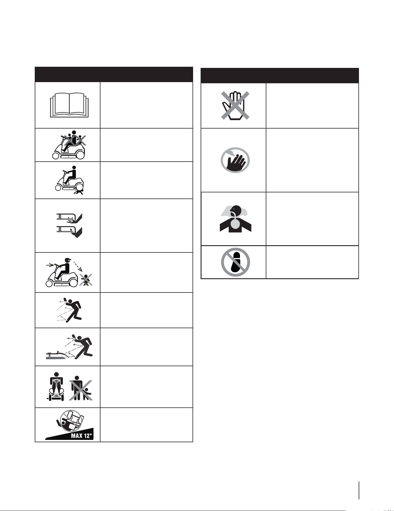
7SECTION 2 —CONSIGNES DE SÉCURITÉ
Symboles de sécurité
$FUUFQBHFJMMVTUSFFUFYQMJRVFMFTTZNCPMFTEFTÏDVSJUÏRVJQFVWFOUTFUSPVWFSTVSDFUUFNBDIJOF7FVJMMF[MJSFFUTVJWSFUPVUFTMFT
instructions sur la machine et vous assurer de bien les comprendre avant d’essayer d’assembler et d’utiliser la machine.
Symbole Description
7&6*--&;-*3&-"06-&4/05*$&4
%65*-*4"5*0/
Veuillez lire et suivre toutes les instruc-
tions sur la machine et vous assurer de
bien les comprendre avant d’essayer
d’assembler et d’utiliser la machine.
%"/(&3-".&4&/.067&.&/5
Ne transportez jamais d’enfants, même
si les lames ne tournent pas.
%"/(&3o-".&4&/.067&.&/5
1PVSÏWJUFSUPVUBDDJEFOUFOSFDVMBOU
éloignez les enfants du tracteur quand
il est utilisé.
"7&35*44&.&/5o-".&4&/.067&-
MENT
N’approchez pas les mains ni les pieds
des pièces en mouvement et ne les
placez pas sous le plateau de coupe.
Tout contact avec les lames peut
amputer les mains ou les pied.
%"/(&3o-".&4&/.067&.&/5
Regardez toujours derrière vous sur le
sol avant de reculer et en reculant pour
éviter tout accident.
"7&35*44&.&/5o0#+&54130+&5²4
Cette machine peut ramasser et
projeter des objets, ce qui peut causer
des blessures graves.
"7&35*44&.&/5o0#+&54130+&5²4
Cette machine peut ramasser et
projeter des objets, ce qui peut causer
des blessures graves.
%"/(&3o41&$5"5&634
(BSEF[MFTTQFDUBUFVSTMFTBOJNBVYEF
compagnie et les enfants à une distance
EBVNPJOTQJFETEFMBNBDIJOF
quand elle est en marche
"7&35*44&.&/5*/$-*/0.µ53&
Ne tondez pas sur des pentes supéri-
eures à 12°.
Symbole Description
"7&35*44&.&/5o463'"$&$)"6%&
Les pièces du moteur, en particulier
MFTJMFODJFVYPOUUFOEBODFËDIBVGGFS
pendant le fonctionnement de la ma-
DIJOF-BJTTF[MFNPUFVSFUMFTJMFODJFVY
refroidir avant de les toucher.
%"/(&3o-".&4&/.067&.&/5
1PVSÏWJUFSMFTSJTRVFTEFCMFTTVSFT
n’approchez jamais les mains ni les
pieds des pièces en mouvement.
N’utilisez pas la machine si le déflecteur
de la goulotte ou si le sac à herbe n’est
pas en place. S’ils sont endommagés,
remplacez-les immédiatement.
"7&35*44&.&/5o.0/09:%&%&
$"3#0/&
Ne faites jamais fonctionner un moteur
à l’intérieur ou dans un bâtiment
mal ventilé. Les gaz d’échappement
DPOUJFOOFOUEVNPOPYZEFEFDBSCPOF
un gaz inodore et mortel.
%"/(&3-".&4&/.067&.&/5
Ne montez pas sur le plateau de coupe.
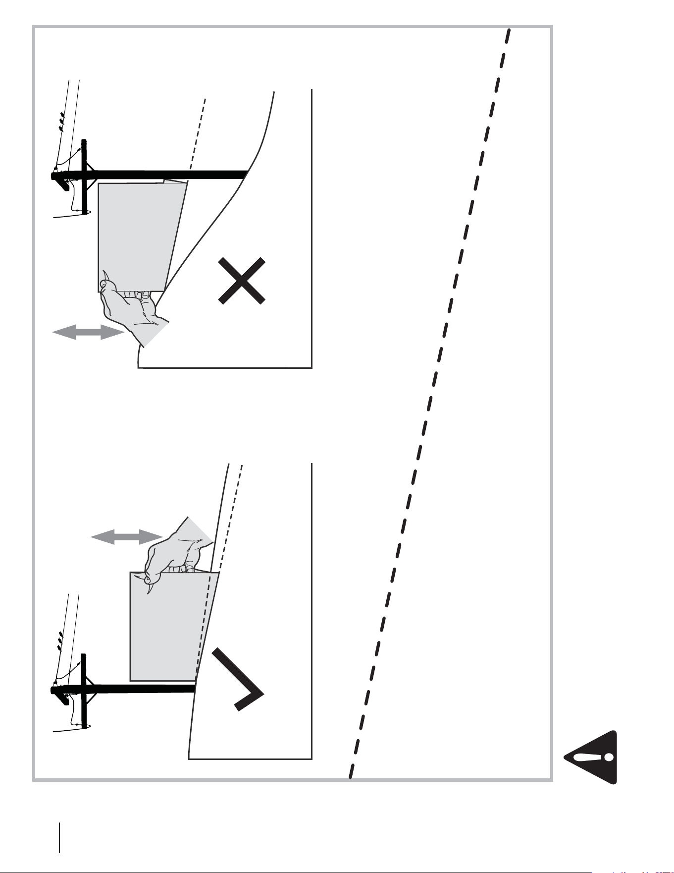
8 SECTION 2 — IMPORTANTES CONSIGNES DE SÉCURITÉ
(OK) (TROP ABRUPTE)
UTILISEZ CET INCLINOMÈTRE POUR DÉTERMINER SI UNE PENTE EST TROP
ABRUPTE POUR PERMETTRE L’UTILISATION SANS DANGER DE LA MACHINE.
Procédez comme suit pour vérifier la pente :
1. Détachez cette page et pliez-la en suivant la ligne pointillée.
2. Trouvez un objet vertical sur ou derrière la pente (un poteau téléphonique, une clôture, un arbre, etc.).
3. Alignez un côté de cette page avec l’objet (Voir les Figures 1 et 2).
4. Remontez ou abaissez l’inclinomètre jusqu’à ce que le coin gauche touche la pente (Voir les Figures 1 et 2).
5. S’il y a un espace sous l’inclinomètre, la pente est trop abrupte pour y travailler en toute sécurité. (Voir la Figure 2 ci-dessus).
Ligne pointillée à12°
Figure 2Figure 1
Pente à12°
Pente à12°
AVERTISSEMENT: Les accidents provoqués par des chutes et des glissades, qui surviennent souvent sur des pentes,
peuvent causer des blessures graves. Ne travaillez pas sur des pentes supérieures à 12 degrés. Travailler sur un terrain en
pente demande des précautions supplémentaires. Si vous pouvez pas remonter la pente en reculant ou si vous ne vous y
sentez pas à l’aise, n’y travaillez pas. Travaillez toujours parallèlement à la pente, jamais perpendiculairement.
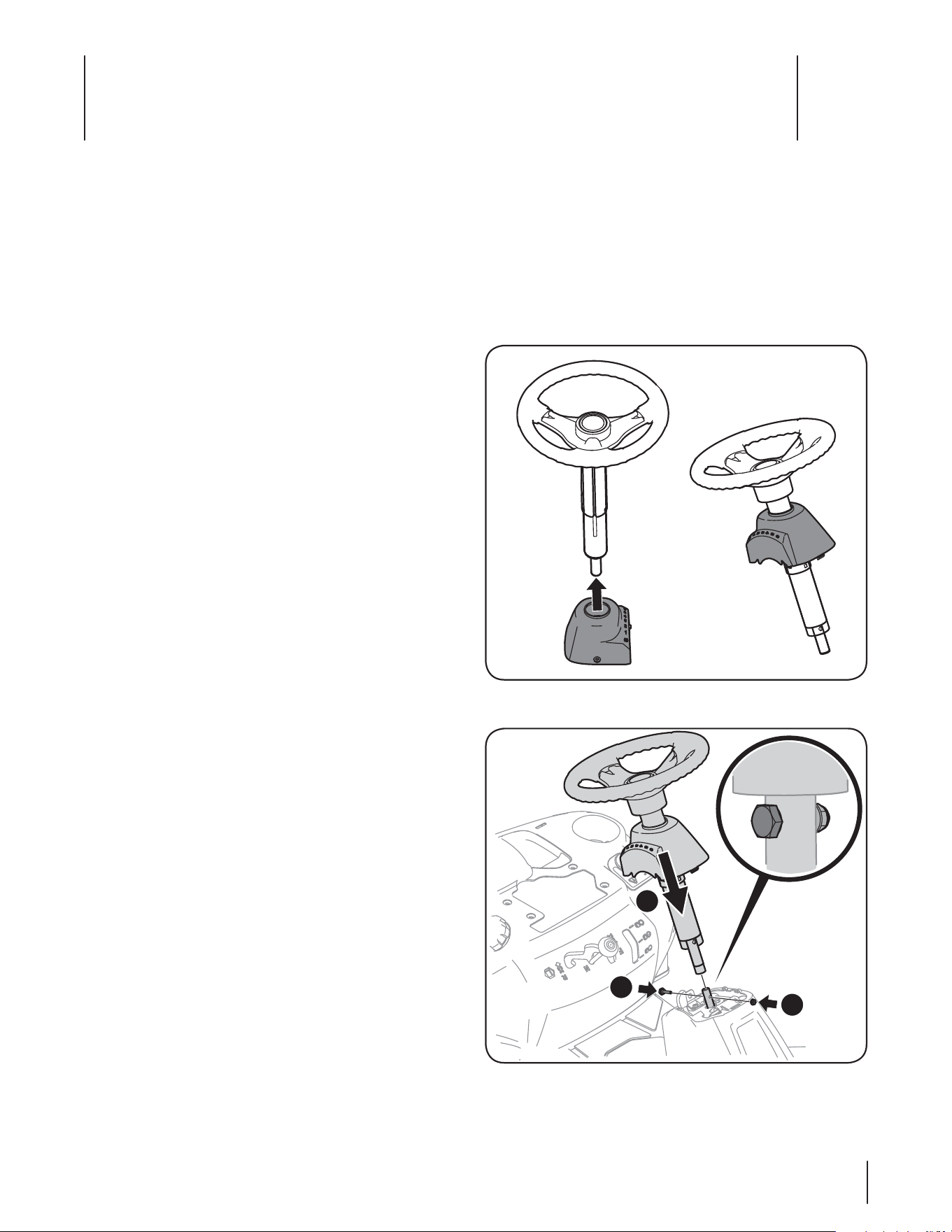
Contenu du sachet de boulonnerie
"WBOUEFDPNNFODFSMJOTUBMMBUJPOWJEF[DPNQMÒUFNFOUMFDBSUPO
FUTPSUF[UPVUFMBCPVMPOOFSJFEVTBDIFU"TTVSF[WPVTRVJMOF
manque aucune pièce. La boulonnerie est énumérée ci-dessous
et les numéros de pièce sont indiqués entre parenthèses.
t 1MBRVFEBUUFMBRF
Outils recommandés pour l’assemblage
t 6OFDMÏEFQPPVDMÏËNPMFUUF
t 6OFDMÏEFQPPVDMÏËNPMFUUF
t 5PVSOFWJT1IJMMJQT
t 3BUDIFUEJTRVFEFQP
t 6OFDMÏËEPVJMMFEFQPPVDMÏ
t 6OFDMÏEFQP
Installation du volant
Si le volant n’a pas été assemblé à l’usine, procédez comme suit :
1. Faites glisser le capuchon sur la colonne de direction de
façon que, lorsque l’arbre de direction est installé sur le
tracteur, le capuchon se présente comme ci-dessous. Voir
la Figure 3-1.
2. Enlevez la boulon à épaulement et le contre-écrou de
l’arbre de direction et gardez-les pour les utiliser à nouveau
plus tard.
3. Tenez le volant à la verticale, bien au-dessus de la partie
inférieure de l’arbre de direction ; alignez le volant pour
que les roues du tracteur soient bien droites la grande
ouverture sur le volant devant se trouver vers l’avant.
"CBJTTF[MFWPMBOUTVSMBQBSUJFJOGÏSJFVSFEFMBSCSFEF
direction et maintenez-le en place avec la boulon à
ÏQBVMFNFOUFUMFDPOUSFÏDSPVFOMFWÏTQMVTUÙU7PJSMB
Figure 3-2.
NOTE: S’assurer d’aligner le boulon à épaulement sorte que
la tête du boulon s’intègre dans le trou prévu sur l’arbre de
direction supérieure une fois serré.
5. Serrez la boulon à épaulement et le contre-écrou avec une
DMÏËDMJRVFUEFQPFUVOFDMÏËDMJRVFUEFQPPV
douille.
Contenu du carton
t Une tondeuse à siège t Un siège t Un capuchon de la colonne de direction
t Un volant/arbre de direction t Un capot de moteur arrière t Une goulotte d’éjection
t Un manchon de vidange de l’huile t Un sachet de boulonnerie t Une notice d’utilisation de la moteur
t Une notice d’utilisation de la
tondeuse à siège
Figure 3-1
Figure 3-2
1
2
2
Assemblage et Montage
3
9
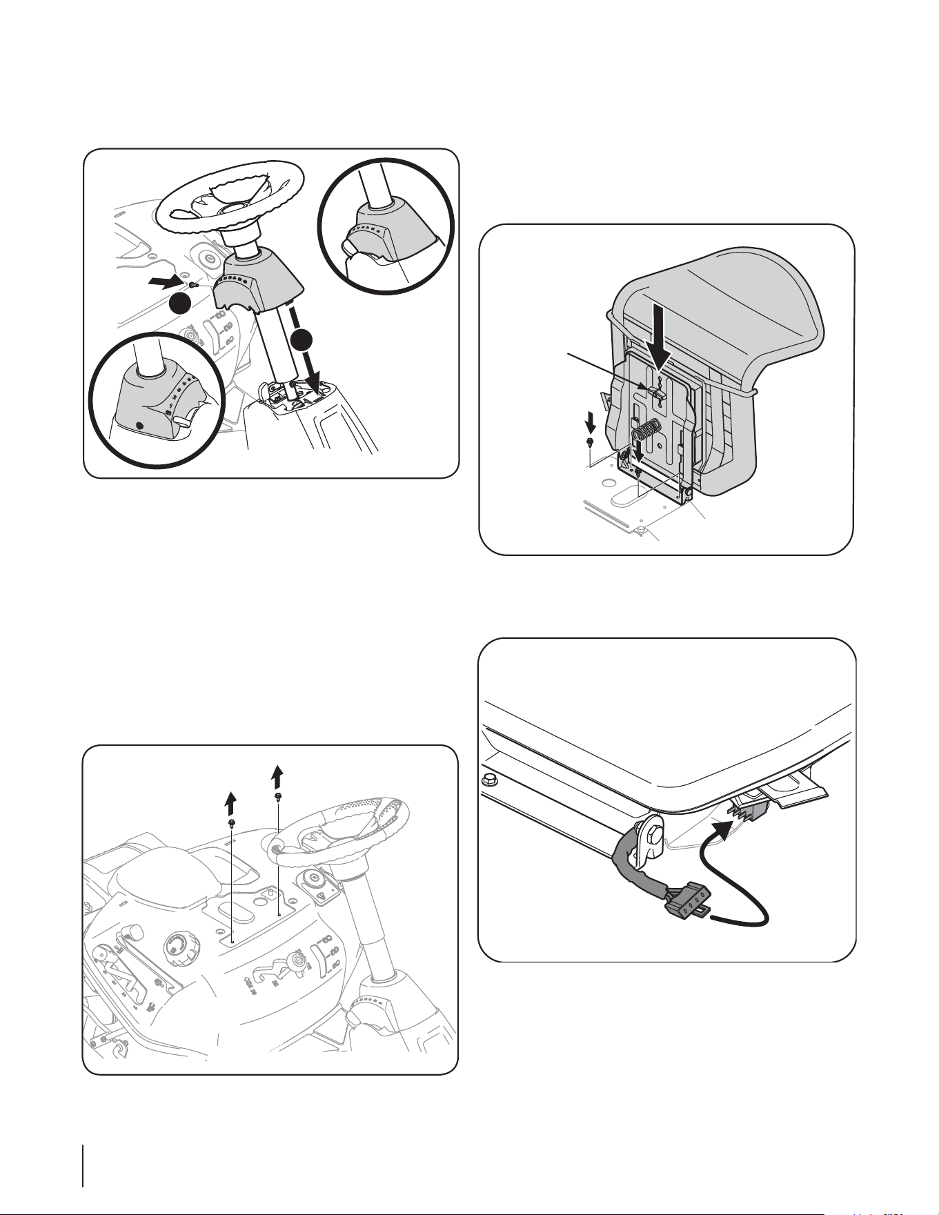
2. 1PTJUJPOOF[MFTJÒHFBVEFTTVTEFTUSPVT7PJSMB'JHVSF
3. 'JYF[MFOTFNCMFEVTJÒHFBWFDMFTWJTBVUPUBSBVEFVTFT
retirées précédemment.
ATTENTION : N’utilisez pas d’outils électriques (pistolet à
percussion ou perceuse électrique avec accessoire pour
WJTQPVSTFSSFSMFTWJTBVUPUBSBVEFVTFTQPVSJOTUBMMFSMF
support du siège sur le tracteur.
Branchez le harnais de sécurité sur le siège dans le faisceau
de câblage sur l’unité comme illustré à la figure 3-6.
5. 1PVSSÏHMFSMBQPTJUJPOEVTJÒHFEFTTFSSFSMFCPVUPOEF
réglage sur la partie inférieure du siège. Faites glisser le
siège vers l’avant ou vers l’arrière comme désiré. Resserrez
le bouton de réglage. Reportez-vous à la Figure 3-5.
6. Retirez la vis à tête cylindrique installé à l’usine du
couvercle de colonne situé sur la console de direction du
tracteur. Conservez la vis pour les instructions plus tard.
(MJTTF[MFDPVWFSDMFWFSTMFCBTTVSMFUSBDUFVSFUUPVSOFS
MFHFSFNFOUWFSTMBESPJUFFUFNCPÔUF[FOQMBDF'JYFSMB
DPMPOOFBWFDMBWJTIFYBHPOBMFSFUJSÏFTQSÏDÏEFNNFOU
Voir la Figure 3-3.
Installation du siège
Si le siège n’a pas été installé à l’usine, suivez les instructions
ci-dessous :
1. Utilisez une clé à cliquet de ¼ avec un 3/8 “femelle enlevez
MFTEFVYWJTBVUPUBSBVEFVTFTRVJPOUÏUÏJOTUBMMÏFTË
MVTJOF7PJSMB'JHVSF
1
2
Figure 3-3
Figure 3-4
Figure 3-5
Figure 3-6
Bouton de réglage
10 SECTION 2 — ASSEMBLAGE & MONTAGE
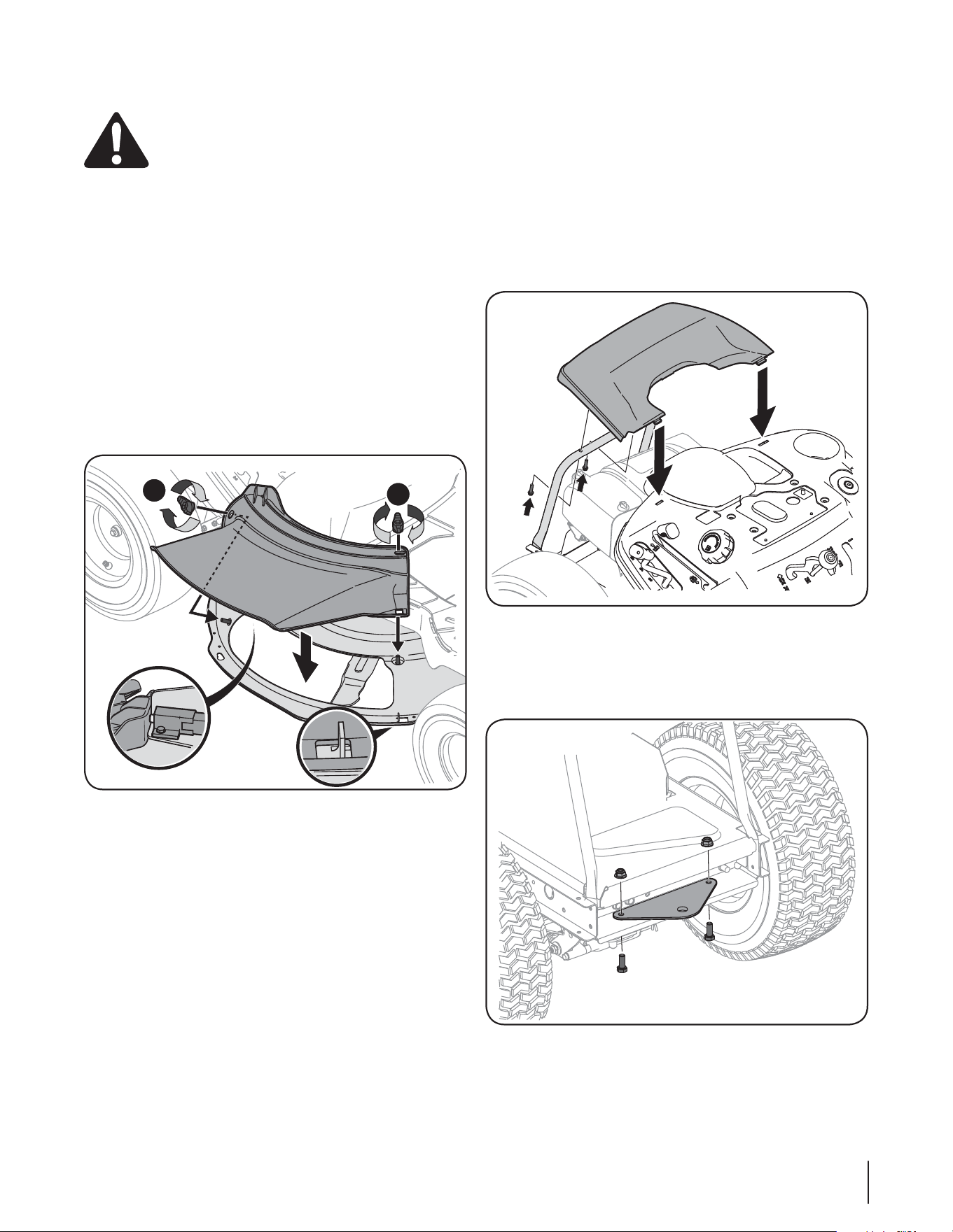
Installation de la goulotte d’éjection
AVERTISSEMENT /VUJMJTF[+"."*4MFUSBDUFVS
sans la goulotte d’éjection ou le bouchon de
déchiquetage.
1. Enlevez les bouton à oreilles installé sur le plateau de
coupe et gardez-le pour l’utiliser plus tard.
2. *OTUBMMF[MBHPVMPUUFEÏKFDUJPOEBOTMPVWFSUVSFEVQMBUFBV
EFDPVQF-FTQPUFBVYTVSMBTVSGBDFEVQMBUFBVEFDPVQF
s’adapte à travers les trous de la partie supérieure de la
goulotte d’éjection. La petite languette sur la zone de la
lèvre du plateau s’adaptera à travers la découpé carrée sur
MBQBSUJFJOGÏSJFVSFEFMBHPVMPUUFEÏKFDUJPO7PJS'JHVSF
Remarque "TTVSF[WPVTRVFMBQBSUJFTVQÏSJFVSFBSSJÒSF
de la goulotte d’éjection appuie sur l’interrupteur de
sécurité situé sur la surface du plateau. Le moteur ne
démarre pas sans la goulotte bien en place.
3. 'JYFSMBHPVMPUUFEÏKFDUJPOFOTFSSBOUMFTCPVUPOBPSFJMMFT
SFUJSÏQMVTUÙU7PJS'JHVSF
Installation du capot de moteur arrière
1. 3FUJSF[MFTEFVYWJTIFYBHPOBMFTJOTUBMMÏFTFOVTJOFTJUVFT
sur le capot moteur. Conservez les vis pour des instruction
plus tard. Voir Figures 3-8.
2. *OTUBMMF[MFDBQPUEFNPUFVSBSSJÒSFFOMFQMBÎBOUDPNNF
à la Figure 3-8. Faites-le basculer vers l’avant pour l’ajuster
dans les fentes aménagées, puis inclinez-le vers l’arrière
pour aligner les trous de montage.
3. "UUBDIF[MFDBQPUBWFDMFTEFVYWJTSFUJSÏFTQSÏDÏEFNNFOU
/FMFTTFSSF[QBTFYDFTTJWFNFOU
Installation de la plaque d’attelage
1. Retirez le matériel installé en usine plaque d’attelage de
NPOUBHFTJUVÏFTVSMBQMBRVFEBUUFMBHF7PJSMBGJHVSF
2. 1PTJUJPOOF[MBQMBRVFEBUUFMBHFDÙUÏQMBUWFSTMFIBVU
DPNNFTVSMB'JHVSF'JYF[ËMBJEFEFEFVYCPVMPOTFU
écrous retirés précédemment.
Figure 3-7
Figure 3-8
Figure 3-9
1
2
11SECTION 2 — ASSEMBLAGE & MONTAGE
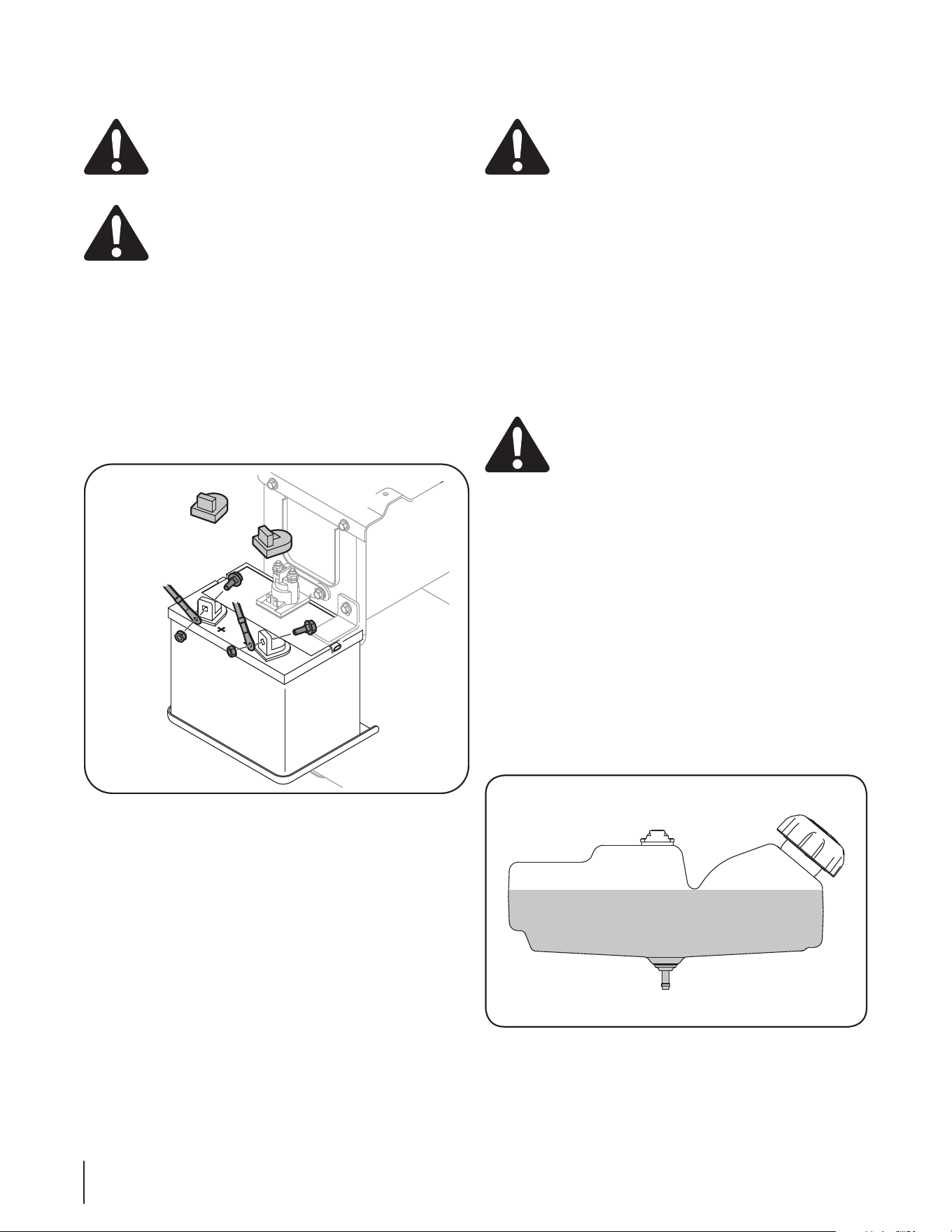
Installation des câbles de la batterie.
AVERTISSEMENT: Les gaz d’échappement de ce
produit contiennent des produits chimiques
reconnus dans l’État de Californie comme causant le
cancer, des anomalies congénitales ou d’autres
problèmes liés à la reproduction.
AVERTISSEMENT : En attachant les câbles de la
CBUUFSJFCSBODIF[UPVKPVSTMFDÉCMF104*5*'SPVHF
TVSMBCPSOFQPTJUJWFQVJTMFDÉCMF/²("5*'OPJS
1PVSEFTSBJTPOTEFYQÏEJUJPOMFTEFVYDÉCMFTEFMBCBUUFSJF
sur votre équipement ont pu avoir été laissés débranchés des
CPSOFTËMVTJOF1PVSCSBODIFSMFTDÉCMFTEFMBCBUUFSJFQSPDÏEF[
comme suit :
REMARQUE: La borne positive de la batterie est identifiée par
1PTFUMBCPSOFOÏHBUJWFQBS/ÏH
1. Enlevez le couvercle en plastique, si équipé, de la borne
positive de la batterie et attachez le câble rouge à la borne
QPTJUJWFEFMBCBUUFSJFBWFDMFCPVMPOFUMÏDSPVËTJY
pans. Voir la Fig. 3-10.
2. Enlevez le couvercle en plastique, si équipé, de la borne
négative de la batterie et attachez le câble noir à la borne
OÏHBUJWFEFMBCBUUFSJFBWFDMFCPVMPOFUMÏDSPVËTJY
pans. Voir la Fig. 3-10.
3. 1MBDF[MBHBJOFFODBPVUDIPVDSPVHFBVEFTTVTEFMBCPSOF
positive de la batterie pour aider à la protéger contre la
corrosion.
REMARQUE: Si la batterie est mise en service après la date
indiquée sur le dessus de la batterie, chargez-la selon les
instructions dans la chapitre «Entretien» dans cette notice
d’utilisation avant d’utiliser le tracteur.
Pression des pneus
AVERTISSEMENT: 6OFQSFTTJPONBYJNBMFEF
lb/po
2
est toujours recommandée. Maintenez
toujours une pression égale dans tous les pneus. Ne
EÏQBTTF[KBNBJTMBQSFTTJPONBYJNBMFJOEJRVÏFTVS
le flanc du pneu.
1PVSDFTQOFVTMBQSFTTJPOSFDPNNBOEÏFFTUEF
t MCQP
2
environ pour les pneus arrière ;
t 20 lb/po
2
environ pour les pneus avant.
IMPORTANT 7ÏSJGJF[MBQSFTTJPONBYJNBMFFYBDUFJOEJRVÏFTVS
le flanc du pneu, recommandée par le fabricant. Ne la dépassez
jamais. Une pression inégale des pneus peut causer une coupe
inégale.
Pleins d’huile et d’essence
Le réservoir d’essence est placé sous le capot et a une capacité
d’un gallon et demi. Ne remplissez pas au-dessus du niveau.
AVERTISSEMENT: Faites très attention en
NBOJQVMBOUEFMFTTFODF*MTBHJUEVOQSPEVJU
hautement inflammable et les vapeurs peuvent
FYQMPTFS/FGBJUFTKBNBJTMFQMFJOËMJOUÏSJFVS
quand le moteur est chaud ou pendant qu’il tourne.
Éteignez les cigarettes, cigares, pipes ou autres
sources de chaleur.
IMPORTANT: Le tracteur est expédié avec une petite quantité
d’huile. Il est toutefois recommandé de vérifier le niveau d’huile
avant de le mettre en marche. Ne remplissez pas au-dessus du
niveau.
Faites les pleins d’huile et d’essence selon les instructions
fournies dans la notice d’utilisation du moteur qui accompagne
le tracteur. Lisez attentivement les instructions.
IMPORTANT: *MFTUJNQPSUBOUEF/&1"4SFNQMJSDPNQMÒUFNFOU
le réservoir de carburant en faisant le plein. Laissez toujours un
FTQBDFQPVSQFSNFUUSFMFYQBOTJPOEVDBSCVSBOUEBOTMFSÏTFSWPJS
FUQPVSBTTVSFSVOFCPOOFWFOUJMBUJPO"VUSFNFOUMBNBDIJOF
risque de ne pas fonctionner correctement. Faites le plein
comme à la Figure 3-11.
Figure 3-10
Figure 3-11
12 SECTION 2 — ASSEMBLAGE & MONTAGE
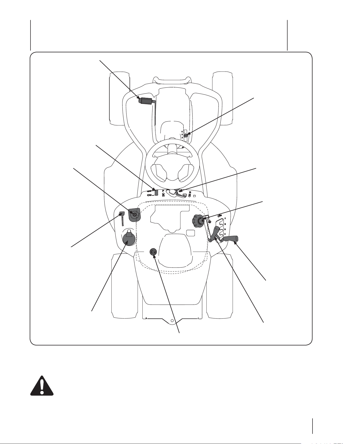
Figure 4-1
Sélecteur de
vitesse & Pédale
d’embrayage/frein
Module du commutateur
d’allumage
Pédale d’embrayage/
frein
Indicateur du niveau du
carburant
Porte-boisson
Manette de commande
de l’obturateur
Bouchon de remplissage de l’huile
Levier de
vitesses
Manette de
relevage du
plateau de coupe
Manette de la prise de force
(Embrayage de la lame)
Capuchon
d’essence
Commandes et caractéristiques
4
13
-FTDPNNBOEFTFUDBSBDUÏSJTUJRVFTEVUSBDUFVSEFQFMPVTFTPOUSFQSÏTFOUÏFTËMB'JHVSFFUTPOUFYQMJRVÏFTEBOTMFTQBHFT
suivantes.
AVERTISSEMENT : Veuillez lire et suivre toutes les consignes de sécurité et instructions, y compris le chapitre
Fonctionnement au complet, qui figurent dans cette notice d’utilisation, avant d’essayer d’utiliser la machine. Le non
respect de ces consignes de sécurité et instructions peut causer des blessures corporelles graves.
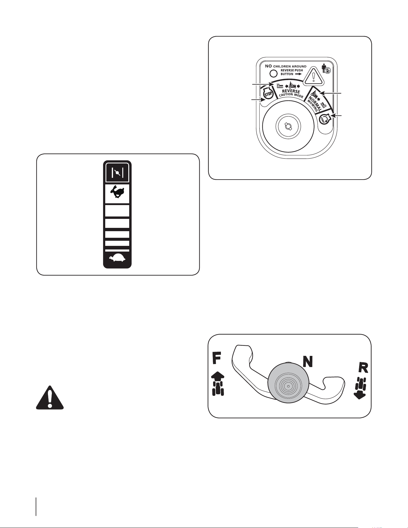
Pédale d’embrayage/frein
Elle se trouve sur la gauche du tracteur de pelouse, le long du
marchepied. Appuyez légèrement sur la pédale d’embrayage/
frein pour ralentir le tracteur avant de changer de vitesse (Voir la
section « Manette de commande de la vitesse »). Appuyez à fond
sur la pédale pour enclencher le frein à disque et arrêter le
tracteur.
REMARQUE: La pédale doit être enfoncée pour faire démarrer le
moteur. Consultez le chapitre « Commutateurs de sécurité », dans
cette notice d’utilisation..
Sélecteur de vitesse
Il se trouve sur le tableau de bord, sous le siège, au milieu du
tracteur. Il offre trois positions, MARCHE AVANT, POINT MORT
et MARCHE ARRIÈRE. La pédale de frein doit être enfoncée
et le tracteur ne doit pas bouger quand vous déplacez le
sélecteur de vitesse. Voir la Figure 4-4.
IMPORTANT: Ne forcez jamais le sélecteur de vitesse. Vous
risqueriez d’endommager la transmission du tracteur.
Figure 4-3
Manette de commande de l’obturateur
Elle se trouve sur la gauche du tableau de bord du tracteur et sert
à régler le régime du moteur, poussez à fond vers l’avant le volet
de départ. L’obturateur maintient le régime du moteur selon le
réglage choisi. Voir la Figure 4-2.
IMPORTANT: Assurez-vous que la manette de commande
de l’obturateur se trouve à la position RAPIDE (lapin) si vous
conduisez le tracteur avec le plateau de coupe embrayé.
Le fait de déplacer la manette de la commande des gaz actionne
la commande du volet de départ. Voir la Figure 4-2. Le bouton
du volet de départ ferme la plaque sur le carburateur et facilite le
démarrage du moteur.
Consultez la partie Démarrage du moteur dans le chapitre
UTILISATION de cette notice d’utilisation.
Module du commutateur d’allumage
Le module du commutateur d’allumage se trouve sur l’aile
gauche du tracteur en position assise du conducteur, à côté de
la manette commande de l’obturateur. Pour mettre le moteur
en marche, enfoncez la clé dans le commutateur d’allumage
et tournez-la dans le sens des aiguilles d’une montre jusqu’à la
position « START » (Mise en marche). Laissez la clé revenir à la
position « NORMAL MOWING MODE » (Tonte normale) quand
le moteur tourne normalement.
Pour arrêter le moteur, tournez la clé dans le sens contraire aux aiguilles
d’une montre, jusqu’à la position « STOP » (Arrêt). Voir la Figure 4-3C.
AVERTISSEMENT: Ne laissez jamais une machine
en marche sans surveillance. Débrayez toujours la
prise de force, placez le levier de vitesses au point
mort, serrez le frein de stationnement, arrêtez le
moteur et retirez la clé pour empêcher tout
démarrage non intentionnel.
IMPORTANT: Avant d’utiliser le tracteur, lisez les instructions plus
détaillées concernant les « Commutateurs de internes sécurité »
et le « Mise en marche du moteur » dans le chapitre UTILISATION
de cette notice d’utilisation. Ces instructions expliquent le
module du commutateur d’allumage.
FAST
SLOW
Figure 4-2
Figure 4-4
Arrêt
Reverse
C
aution Mode
Tonte
normale
Mise
en marche
14 SECTION 4— COMMANDES ET CARACTÉRISTIQUES
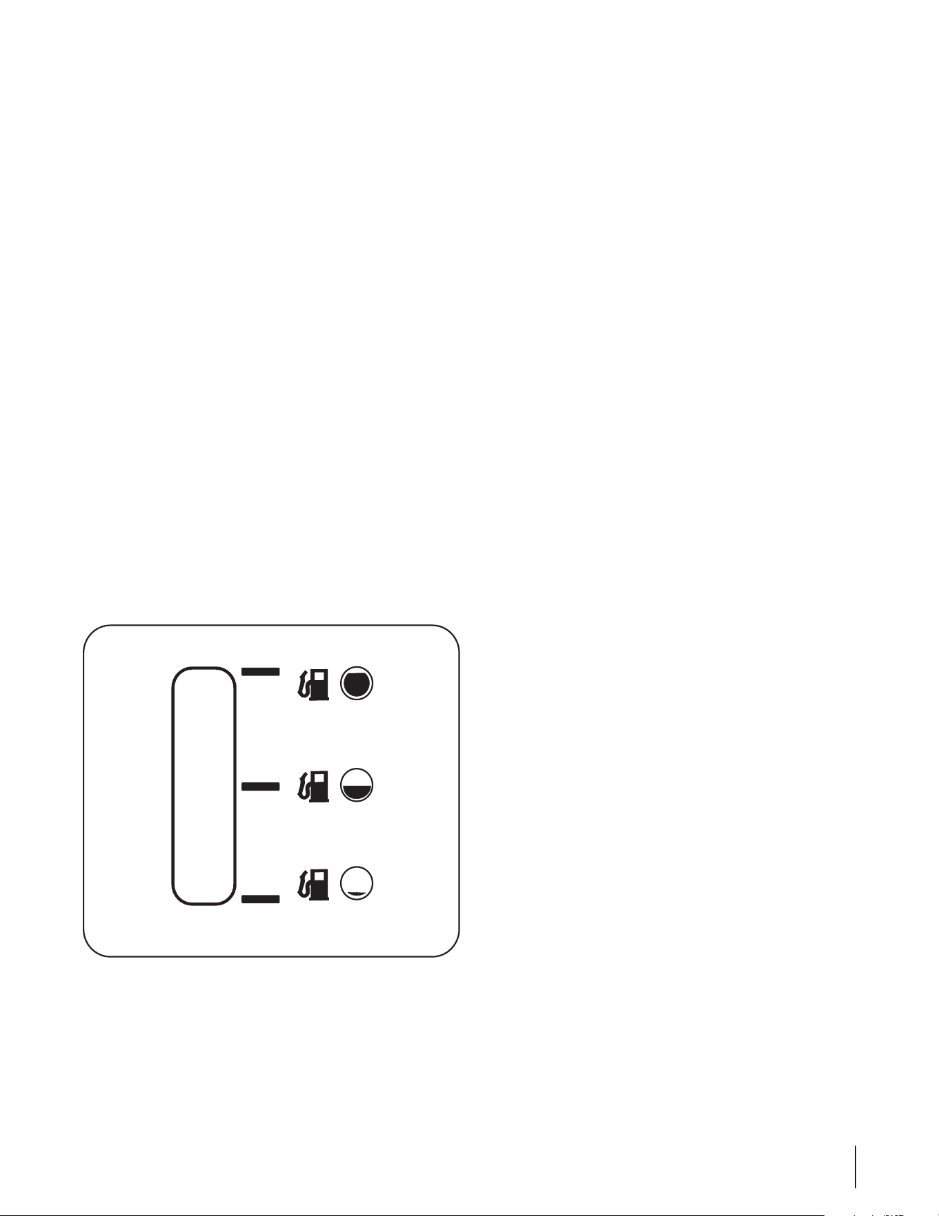
Sélecteur de vitesses
Ce sélecteur de vitesse, placé sur la droite de la console centrale,
permet de régler la vitesse de déplacement du tracteur de
QFMPVTF*MTVGGJUEFOGPODFSMBQÏEBMFEFNCSBZBHFGSFJO
de dégager le sélecteur de vitesse de l’encoche du frein de
stationnement et de le déplacer vers l’avant pour accélérer.
Lorsque la vitesse désirée est atteinte, placez le sélecteur de
vitesse dans l’encoche correspondante pour maintenir cette
vitesse.
1PVSSBMFOUJSBQQVZF[TVSMBQÏEBMFEFNCSBZBHFGSFJOUJSF[MF
sélecteur de vitesse vers l’arrière et placez-le dans une encoche.
Frein de stationnement
1PVSTFSSFSMFGSFJOEFTUBUJPOOFNFOUBQQVZF[ËGPOETVS
la pédale d’embrayage/frein. Tirez le sélecteur de vitesse
à fond vers l’arrière et placez-le dans l’encoche du frein de
stationnement. Retirez votre pied de la pédale d’embrayage/
frein pour serrer le frein de stationnement.
1PVSEFTTFSSFSMFGSFJOEFTUBUJPOOFNFOUBQQVZF[TVSMBQÏEBMF
d’embrayage/frein et déplacez le sélecteur de vitesse à la
position voulue. Lâchez le levier de vitesses et retirez votre pied
de la pédale d’embrayage/frein.
REMARQUE: Le frein de stationnement doit être serré quand le
conducteur quitte son siège si le moteur tourne, sinon le moteur
s’arrêtera automatiquement.
Indicateur du niveau du carburant
*MTFUSPVWFTPVTMFTJÒHFTVSMBHBVDIFEVQPTUFEFDPOEVJUF
dans le tableau de bord. Servez-vous de cet indicateur pour
prévoir les besoins en carburant de votre tracteur. Voir la Figure
Figure 4-5
Manette de relevage du plateau de coupe
Elle se trouve sur le garde-boue de droite du tracteur et sert à
modifier la hauteur du plateau de coupe. Déplacez la manette
vers la gauche, puis placez-la dans l’encoche correspondant à la
position désirée.
Manette de la prise de force
(Embrayage de la lame)
Elle se trouve sur le garde-boue de droite du tracteur. Elle sert à
embrayer le plateau de coupe ou d’autres accessoires (vendus
TÏQBSÏNFOU1PVSFNCSBZFSMFQMBUFBVEFDPVQFQPVTTF[MB
manette à fond. Le fait de tirer la manette à fond vers l’arrière, à
MBQPTJUJPOj1500''x1SJTFEFGPSDFOPOFODMFODIÏFEÏCSBZF
le plateau de coupe/accessoire.
REMARQUE: La manette de la prise de force (embrayage de la
MBNFEPJUTFUSPVWFSËMBQPTJUJPOOPOFNCSBZÏFËMBNJTFFO
marche du moteur.
Capuchon de remplissage du carburant
*MTFUSPVWFTPVTMFTJÒHF$POTVMUF[MFDIBQJUSFj.POUBHFxEF
cette notice d’utilisation pour tout renseignement concernant le
plein de carburant du tracteur.
Capuchon de remplissage de l’huile
*MTFUSPVWFTPVTMFTJÒHF$POTVMUF[MFDIBQJUSFj.POUBHFxEBOT
cette notice d’utilisation pour tout renseignement concernant le
plein d’huile.
15SECTION 4— COMMANDES ET CARACTÉRISTIQUES
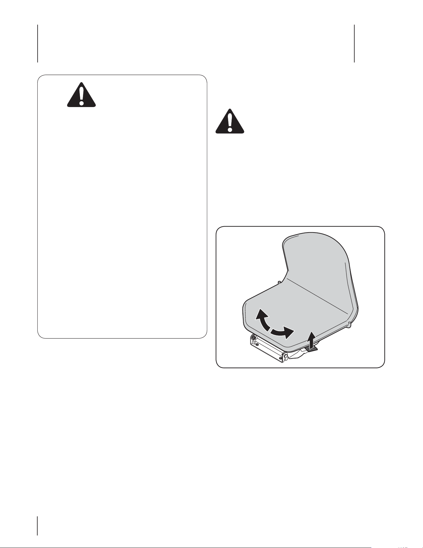
Utilisation
5
16
Commutateurs internes de sécurité
Ce tracteur est muni d’un système de sécurité conçu pour
QSPUÏHFSMFDPOEVDUFVS4JDFTZTUÒNFFTUEÏGFDUVFVYOVUJMJTF[
QBTMFUSBDUFVS"ESFTTF[WPVTËVOFTUBUJPOUFDIOJRVFBHSÏÏF
dans votre région.
t Ce système de sécurité empêche le moteur de tourner et
de démarrer si la pédale de frein n’est pas complètement
enfoncée et si la manette de la prise de force (embrayage
EFMBMBNFOFTUQBTËMBQPTJUJPOOPOFODMFODIÏF0''
t Le système de sécurité arrête automatiquement le moteur
si le conducteur quitte son siège avant de serrer le frein de
stationnement.
t Le moteur s’arrête automatiquement quand le conducteur
quitte le poste de conduite alors que la manette de la prise
EFGPSDF&NCSBZBHFEFMBMBNFTFUSPVWFËMBQPTJUJPOj0/
x&NCSBZÏFRVFMFGSFJOEFTUBUJPOOFNFOUTPJUTFSSÏPV
non.
t Le moteur s’arrête automatiquement si la manette de
MBQSJTFEFGPSDF&NCSBZBHFEFMBMBNFFTUQMBDÏFËMB
QPTJUJPOj0/x&NCSBZÏFBMPSTRVFMFMFWJFSEFWJUFTTFTTF
trouve à la position de marche arrière.
AVERTISSEMENT: N’utilisez pas le tracteur si le
système de sécurité ne fonctionne pas
correctement. Ce système est conçu pour votre
sécurité et pour votre protection.
Siège pivotant
Ce tracteur est équipé d’un siège pivotant qui facilite l’accès et la
sortie du poste de conduite par le conducteur.
Remarque : Le siège doit faire face à l’avant pour que le tracteur
se mette en marche.
1PVSVUJMJTFSMFTJÒHFQJWPUBOU
1. Si le siège fait face à l’avant, relevez la manette qui se
trouve sur la gauche du siège et pivotez le siège vers la
gauche. Lâchez la manette. Voir la Fig. 5-1.
2. "TTFZF[WPVTSFMFWF[MBNBOFUUFRVJTFUSPVWFTVSMBESPJUF
du siège et pivotez le siège en position de conduite.
3. Lâchez la manette.
Remarque$POTVMUF[MBTFDUJPOj*OTUBMMBUJPOEVTJÒHFx
dans le chapitre « Montage » de cette notice d’utilisation
pour tout renseignement sur le réglage de la position du
siège.
A
VERTISSEMEN
T
ÉVITEZ DES BLESSURES GRAVES OU MORTELLES
t 53"7"*--&;1"3"--µ-&.&/5®-"1&/5&+"."*4
1&31&/%*$6-"*3&.&/5
t ²7*5&;%&5063/&3#36426&.&/5
t /65*-*4&;1"4-&53"$5&634*-3*426&%&(-*44&3
06%&#"4$6-&3
t 4*-"."$)*/&4"33³5&&/(3*.1"/56/&1&/5&
"33³5&;-&4-".&4&53&$6-&;-&/5&.&/5
t /&50/%&;+"."*4®1309*.*5²%&/'"/5406
%"653&441&$5"5&634
t ."*/5&/&;5064-&4%*4104*5*'4%&4²$63*5²&/
#0/²5"5%*4104*5*'4%&1305&$5*0/²$3"/4&5
$0..65"5&634
t &/-&7&;-&40#+&5426*3*426&/5%³53&130+&5²4
1"3-&4-".&4
t '".*-*"3*4&;7064"7&$-&.1-"$&.&/5&5-"
'0/$5*0/%&5065&4-&4$0.."/%&4
t 7²3*'*&;26&-&4-".&4&5-&.05&634&40/5
"33³5²4"7"/5%&/"1130$)&3-&4."*/406-&4
1*&%4
t "7"/5%&26*55&3-&1045&%&$0/%6*5&%²#3":&;
-&4-".&41-"$&;-&4²-&$5&63%&7*5&44&"6
10*/5.0354&33&;-&'3&*/%&45"5*0//&.&/5
"33³5&;-&.05&63&5&/-&7&;-"$-²
LISEZ LA NOTICE D’UTILISATION.
Figure 5-1
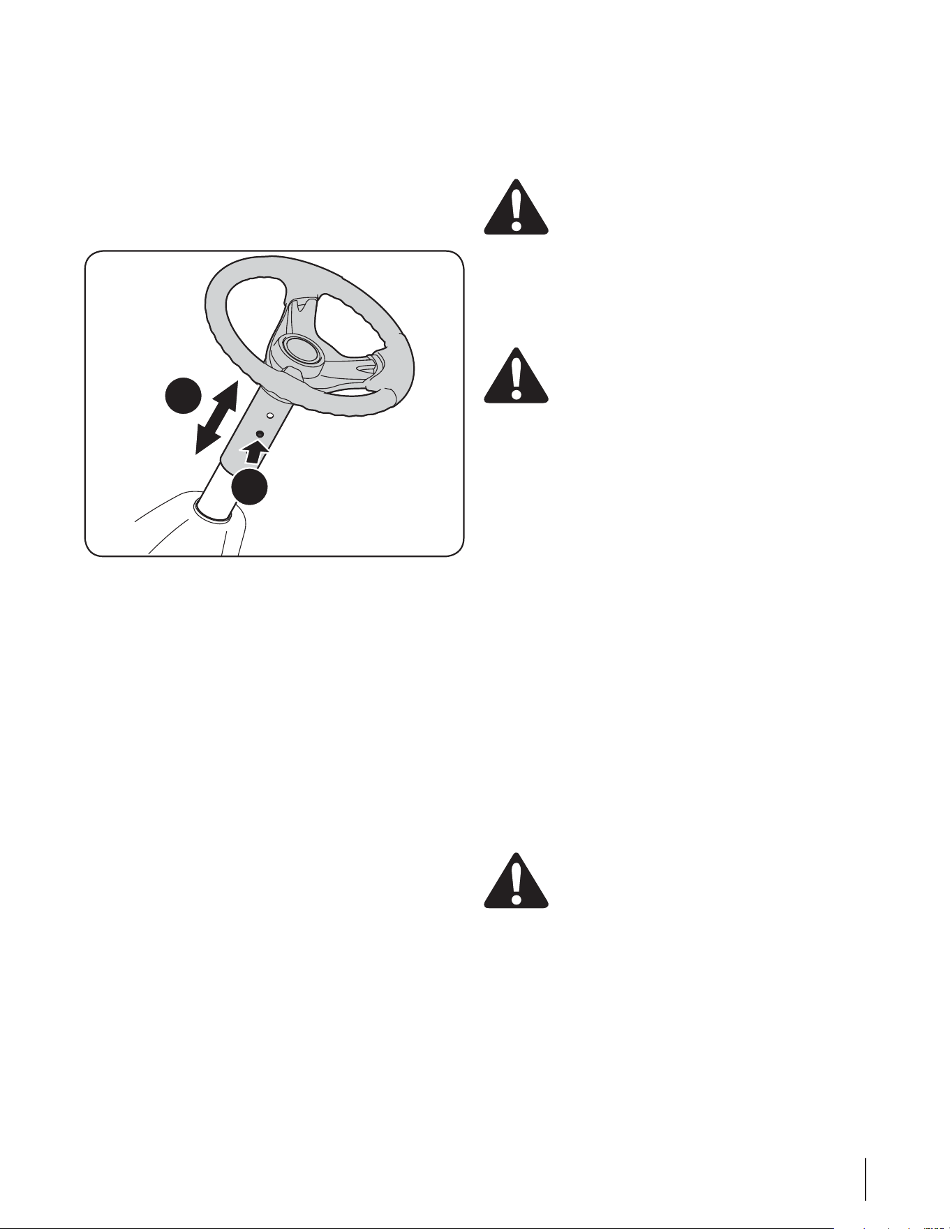
17SECTION 5 — UTILISATION
Réglage de la hauteur du volant (le cas échéant)
Ce tracteur peut être équipé d’une colonne de direction
UÏMFTDPQJRVF1PVSBKVTUFSMBIBVUFVSEVWPMBOU
1. "TTFZF[WPVTËMBQPTJUJPOEFDPOEVJUFFUQMBDF[MFTNBJOT
sur le volant.
2. 1PVTTF[TVSMFCPVUPOBTVSMBDPMPOOFEFEJSFDUJPOFU
SFMFWF[PVBCBJTTF[MFWPMBOUCËMBIBVUFVSEÏTJSÏF7PJSMB
Figure 5-2.
Remarque : Une fois le volant à la hauteur voulue, relevez
et abaissez celui-ci pour qu’il se bloque en position.
N’utilisez pas le tracteur si la colonne de direction n’est pas
bloquée.
Enclenchement du frein de stationnement
Pour enclencher le frein de stationnement :
1. "QQVZF[ËGPOETVSMBQÏEBMFEFNCSBZBHFGSFJO
2. Tirez le sélecteur de vitesse à fond vers l’arrière et placez-le
dans l’encoche du frein de stationnement.
3. Retirez votre pied de la pédale d’embrayage/frein pour
serrer le frein de stationnement.
Pour deserrer le frein de stationnement :
1. "QQVZF[MÏHÒSFNFOUTVSMBQÏEBMFEFEÏCSBZBHFGSFJOFU
déplacez le sélecteur de vitesse hors de la position de frein
de stationnement.
Réglage de la hauteur de coupe
1. Choisissez la hauteur du plateau de coupe en plaçant la
manette de relevage du plateau dans l’une des encoches
sur le garde-boue de droite.
AVERTISSEMENT : N’approchez pas les mains et
les pieds de l’ouverture de la goulotte d’éjection du
plateau de coupe.
CONSULTEZ « Mise à niveau du plateau de coupe» dans le
DIBQJUSF3²(-"(&4EBOTDFUUFOPUJDFEVUJMJTBUJPORVBOUBVY
divers réglages du plateau de coupe.
Mise en marche du moteur
AVERTISSEMENT : N’utilisez pas le tracteur si le
TZTUÒNFEFTÏDVSJUÏFTUEÏGFDUVFVY$FTZTUÒNFË
été conçu pour votre sécurité et protection.
REMARQUE: $POTVMUF[MFDIBQJUSF.0/5"(&%653"$5&63Ë
MBQBHFEBOTDFUUFOPUJDFEVUJMJTBUJPORVBOUBVYJOTUSVDUJPOT
concernant les pleins d’essence et d’huile.
1. *OTÏSF[MBDMÏEVUSBDUFVSEBOTMFDPNNVUBUFVSEBMMVNBHF
2. 1MBDF[MBNBOFUUFEFMBQSJTFEFGPSDFFNCSBZBHFEFMB
MBNFËMBQPTJUJPO0''OPOFODMFODIÏF
3. "QQVZF[TVSMBQÏEBMFEFGSFJOFUTFSSF[MFGSFJOEF
stationnement.
Déplacez la commande de volet de départ
5. Tournez la clé dans le sens des aiguilles d’une montre,
KVTRVËMBQPTJUJPO45"35%ÏNBSSBHF2VBOEMFNPUFVS
UPVSOFMÉDIF[MBDMÏ&MMFSFWJFOUËMBQPTJUJPO0/.BSDIF
IMPORTANT: /FUFOF[QBTMBDMÏËMBQPTJUJPO45"35%ÏNBSSBHF
pendant plus de 10 secondes, car vous risquez d’endommager le
démarreur.
6. 2VBOEMFNPUFVSUPVSOFEÏHBHF[MBNBOFUUFEVWPMFUEF
départ et placez la manette de l’obturateur à la position «
'"45x3BQJEF
REMARQUE : N’utilisez pas le tracteur si le volet de départ est
fermé. Le mélange de carburant serait trop riche et le moteur
risquerait de tourner de façon peu performante.
Arrêt du moteur
AVERTISSEMENT "SSÐUF[MFNPUFVSBQSÒTBWPJS
heurté un objet quelconque. Débranchez le fil de la
bougie, mettez-le à la masse contre le moteur.
Vérifiez soigneusement que la tondeuse n’est pas
endommagée. Réparez les dégâts éventuels avant
de remettre la tondeuse en route.
1. 1MBDF[MBNBOFUUFEFMBQSJTFEFGPSDFFNCSBZBHFEFMB
MBNFËMBQPTJUJPO0''OPOFODMFODIÏF
2. 5PVSOF[MBDMÏEBOTMFTFOTDPOUSBJSFBVYBJHVJMMFTEVOF
NPOUSFKVTRVËMBQPTJUJPO0''"SSÐU
3. Retirez la clé de l’allumage pour empêcher tout démarrage
accidentel.
a
b
Figure 5-2

18 SECTION 5— UTILISATION
Conduite du tracteur
AVERTISSEMENT : Évitez les démarrages brusques,
UPVUFWJUFTTFFYDFTTJWFFUMFTBSSÐUTTPVEBJOT
AVERTISSEMENT :Ne quittez pas le poste de
conduite sans avoir d’abord placé la manette, de la
QSJTFEFGPSDFFNCSBZBHFEFMBMBNFËMBQPTJUJPO
0''OPOFODMFODIÏFFOGPODÏMBQÏEBMFEFGSFJO
et serré le frein de stationnement. Si vous laissez le
tracteur sans surveillance, pensez à retirer la clé.
AVERTISSEMENT 1PVSÏMJNJOFSUPVUSJTRVF
d’accident en marche arrière, regardez toujours
derrière vous et au niveau du sol avant de faire
marche arière et en reculant.
1. 1MBDF[MBNBOFUUFEFMPCUVSBUFVSËMBQPTJUPO'"45MBQJO
2. 1MBDF[MFTÏMFDUFVSEFWJUFTTFËMBQPTJUJPOj'038"3%x
.BSDIFBWBOUPVj3&7&34&x.BSDIFBSSJÒSF
3. "QQVZFSTVSMBQÏEBMFEFNCSBZBHFFUEFGSFJOFUEÏQMBDFS
le levier de commande de vitesse hors de la position du
frein de stationnement en position de vitesse désirée.
IMPORTANT: Ne vous servez pas du levier de vitesses pour
changer de direction quand le tracteur est en mouvement.
Utilisez toujours la pédale de frein pour arrêter complètement le
tracteur avant de changer de vitesse.
IMPORTANT: *MFTUDPOTFJMMÏBVYDPOEVDUFVSTOPWJDFTEFOVUJMJTFS
que les vitesses 1 ou 2. Familiarisez-vous davantage avec le
fonctionnement et les commandes du tracteur avant d’utiliser les
vitesses supérieures.
Lâchez lentement la pédale d’embrayage/frein pour mettre
le tracteur en mouvement.
5. 1PVSBSSÐUFSDPNQMÒUFNFOUMFUSBDUFVSBQQVZF[TVSMB
pédale d’embrayage/frein tout en bas.
REMARQUE : Vous remarquerez peu de différence entre les
EFVYWJUFTTFTTVQÏSJFVSFTUBOURVFMFTDPVSSPJFTOFTFTFSPOU
pas assises correctement dans les poulies pendant la période de
rodage.
AVERTISSEMENT "WBOUEFRVJUUFSMFQPTUFEF
conduite, débrayez toujours les lames, placez le
sélecteur de vitesse au point mort, serrez le frein de
stationnement, arrêtez le moteur et enlevez la clé.
IMPORTANT: En cas d’arrêt du tracteur sur une surface couverte
d’herbe :
1. 1MBDF[UPVKPVSTMFTÏMFDUFVSEFWJUFTTFBVQPJOUNPSU
2. Serrez le frein de stationnement,
3. "SSÐUF[MFNPUFVSFUFOMFWF[MBDMÏ7PVTÏWJUFSF[BJOTJ
l’apparition sur votre pelouse de taches brunes, causées
par les gaz d’échappement chauds du moteur en marche.
Si le tracteur cale alors que le sélecteur de vitesse se trouve à
une vitesse rapide, ou si le tracteur ne fonctionne pas quand
le sélecteur de vitesse se trouve à une vitesse lente, procédez
comme suit :
1. 1MBDF[MFTÏMFDUFVSEFWJUFTTFBV10*/5.035
2. Faites redémarrer le moteur.
3. 1MBDF[MFTÏMFDUFVSEFWJUFTTFËMBWJUFTTFSBQJEF
Lâchez complètement la pédale d’embrayage/frein.
5. Enfoncez la pédale d’embrayage/frein.
6. 1MBDF[MFTÏMFDUFVSEFWJUFTTFËMBWJUFTTFWPVMVF
1MBDF[MFTÏMFDUFVSEFWJUFTTFËMBQPTJUJPOj'038"3%x
.BSDIFBWBOUPVj3&7&34&x.BSDIFBSSJÒSFFUTVJWF[MFT
procédures normales.
Conduite sur pente
Utilisez M*/$-*/0.µ53&ËMBQBHF 3 pour déterminer si vous
pouvez travailler en tout sécurité sur une pente.
AVERTISSEMENT : Ne conduisez pas sur des
pentes de plus de 15 degrés (soit une élévation de 2
QJFETFOWJSPOQBSQJFET-FUSBDUFVSSJTRVFSBJU
de se retourner et de vous blesser grièvement.
t Travaillez parallélement à la pente, jamais
perpendiculairement.
t Faites très attention en changeant de direction. sur des
pentes.
t 'BJUFTBUUFOUJPOBVYUSPVTPSOJÒSFTCPTTFTSPDIFTPV
autres obstacles cachés. Un terrain irrégulier peut causer
le renversement de la machine. L’herbe haute risque de
cacher des obstacles.
t Évitez de tourner sur une pente. S’il est essentiel de tourner,
virez dans le sens de la pente descendante. Le fait de
tourner sur une pente accroît les risques de renversement.
t Ne vous arrêtez pas sur une pente. Si un arrêt est toutefois
nécessaire, procédez en douceur et démarrez lentement pour
SÏEVJSFBVNBYJNVNMFTSJTRVFTEFSFOWFSTFNFOUEVUSBDUFVS
Embrayage de les lames
L’e m br ay a ge EFMBQSJTFEFGPSDF&NCSBZBHFEFMBMBNF
USBOTGÒSFMBQVJTTBODFOÏDFTTBJSFBVQMBUFBVEFDPVQF1SPDÏEF[
comme suit pour embrayer les lames:
1. 1MBDF[MBNBOFUUFEFDPNNBOEFEFMPCUVSBUFVSËMB
QPTJUJPO'"453BQJEFMBQJO
2. Faites pivoter la manette de la prise de force (Embrayage
EFMBMBNFËGPOEWFSTMBWBOUKVTRVËMBQPTJUJPOj0/x
&NCSBZÏF
3. .BJOUFOF[MBNBOFUUFEFMPCUVSBUFVSËMBQPTJUJPO'"45
MBQJOQPVSHBSBOUJSVOGPODUJPOOFNFOUFGGJDBDFEV
plateau de coupe.
IMPORTANT: La manette de la prise de force (embrayage de
MBMBNFEPJUTFUSPVWFSËMBQPTJUJPOOPOFNCSBZÏFËMBNJTFFO
marche du moteur, en marche arrière et si le conducteur quitte
son siège Consultez la section «Commutateurs de sécurité» dans
DIBQJUSFi6UJMJTBUJPOwEFDFNBOVFM

19SECTION 5 — UTILISATION
UTILISATION de la manette de relevage
Pour relever le plateau de coupe, déplacez la manette de
relevage vers la gauche, puis positionnez-la dans l’encoche
DPSSFTQPOEBOUËMFNQMPJWPVMV$POTVMUF[MBQBSUJF3²(-"(&%&
-")"65&63%&$061&BCPSEÏFQMVTUÙUEBOTDFDIBQJUSF
Tonte de l’herbe
AVERTISSEMENT 1PVSBJEFSËÏWJUFSMFDPOUBDU
avec les lames ou les blessures provoqués par les
PCKFUTQSPKFUÏTHBSEF[MFTTQFDUBUFVSTMFTBOJNBVY
de compagnie et les enfants à une distance d’au
NPJOTQJFETEFMBNBDIJOFRVBOEFMMFFTUFO
NBSDIF"SSÐUF[MBNBDIJOFTJRVFMRVVOTBQQSPDIF
la zone de travail.
Les renseignements suivants seront utiles lors de l’emploi du
plateau de coupe avec le tracteur.
AVERTISSEMENT 1SÏWPZF[EFUSBWBJMMFSFO
évitant de projeter l’herbe vers des rues, des
trottoirs, des spectateurs, etc. Évitez d’éjecter l’herbe
en direction d’un mur ou d’un obstacle. De cette
façon, les débris éventuels ne risquent pas de
ricocher et de blesser quelqu’un.
t Ne tondez pas en vous déplaçant rapidement, surtout si un
ensemble de déchiquetage ou un collecteur d’herbe est
installé.
t Vous obtiendrez de meilleurs résultats en dirigeant l’herbe
DPVQÏFMPSTEFTEFVYQSFNJFSTQBTTBHFTWFSTMFDFOUSFEF
MB[POFEFUSBWBJM1BSMBTVJUFDIBOHF[EFEJSFDUJPOQPVS
ÏWBDVFSMIFSCFDPVQÏFWFSTMFYUÏSJFVS7PUSFQFMPVTFBVSB
ainsi meilleure apparence.
t Ne tondez pas l’herbe trop court. Les mauvaises herbes
pousseraient plus vite et le gazon risque de jaunir plus
rapidement pendant les périodes sèches.
t Tondez toujours à plein régime.
t Si l’herbe est très touffue, il faudra peut-être effectuer un
EFVYJÒNFQBTTBHFQPVSPCUFOJSVOFUPOUFOFUUF
t N’essayez pas de tondre les brousailles, les mauvaises
IFSCFTPVEFMIFSCFFYUSÐNFNFOUIBVUF$FUUF
tracteur est conçue pour l’entretien normal de pelouses
résidentielles.
t Utilisez toujours des lames bien affûtées et remplacez-les
TJFMMFTTPOUVTÏFT$POTVMUF[MFQBSBHSBQIF-".&4EBOTMF
chapitre «Entretien» dans cette notice d’utilisation quant
BVYJOTUSVDUJPOTEBJHVJTBHF
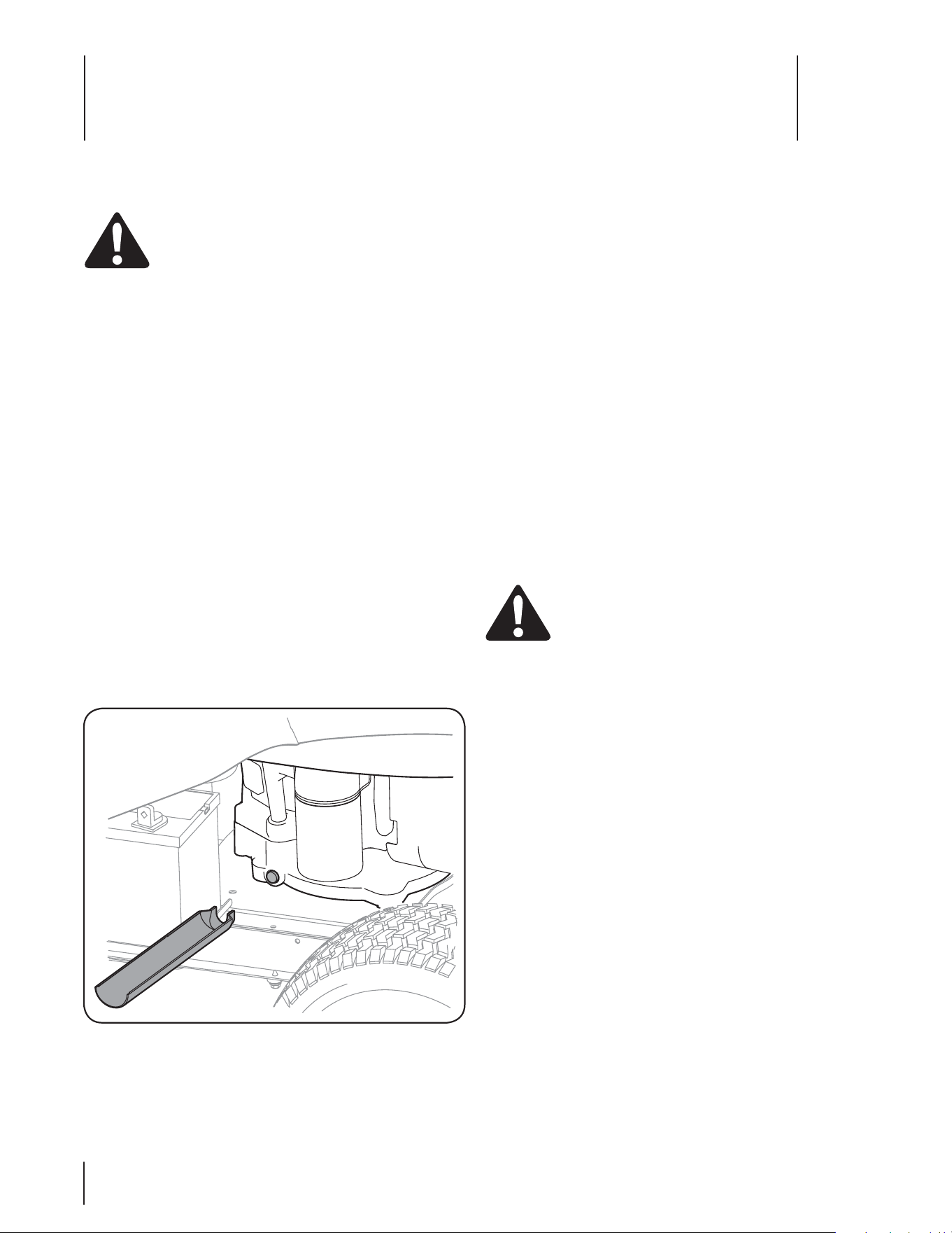
5. Enlevez le bouchon de vidange et laissez l’huile couler dans
un récipient approprié d’une capacité minimale de 64 oz.
6. Remettez le bouchon de vidange en place et serrez-le bien
sans toutefois serrer excessivement.
7. Faites le plein du moteur avec de l’huile à moteur propre,
selon les instructions dans la notice d’utilisation du moteur
qui accompagne votre machine.
IMPORTANT: Faites à nouveau le plein avec la quantité et la
qualité d’huile propre recommandées dans la notice d’utilisation
du moteur.
Filtre à air
Nettoyez le pré-nettoyeur (si équipé), et la cartouche / filtre à air
comme instruit dans la notice d’utilisation du moteur emballée
avec votre machine.
Bougies
Les bougies doivent être nettoyées une fois par saison et
l’écartement des bougies doit être ajusté une fois par an. Il est
recommandé de remplacer la bougie au début de chaque saison
de tonte. Consultez la notice d’utilisation du moteur quant au
modèle de bougie et à l’écartement.
Lubrification
AVERTISSEMENT: Avant de lubrifier, réparer ou
inspecter, débrayez la prise de force , serrez le frein
de stationnement, arrêtez le moteur et retirez la clé
pour empêcher tout démarrage non intentionnel.
Moteur
Lubrifiez le moteur avec une huile à moteur de la qualité
recommandée dans la notice d’utilisation du moteur fournie avec
la machine.
Points de pivotement et timonerie
Lubrifiez tous les points de pivot de la transmission, le frein de
stationnement et la timonerie de relevage au moins une fois par
saison avec une huile légère.
Roues arrière
Démontez les roues arrière des essieux une fois par saison.
Lubrifiez bien les essieux et les jantes avec une graisse
automobile tout usage avant de les installer à nouveau.
Essieux avant
Les deux extrémités de la barre de pivotement avant du tracteur
sont peut-être équipées de raccords graisseurs. Lubrifiez avec un
pistolet graisseur toutes les 25 heures d’utilisation.
Direction à crémaillère
Une fois par saison ou toutes les 25 heures de fonctionnement, il
sera nécessaire de lubrifier la direction à crémaillère qui se trouve
sous l’avant de la machine. Appliquez une graisse automobile
ordinaire sur l’avant et sur l\arrière de la crémaillère, comme à la
Figure 6-2.
Entretien
AVERTISSEMENT : Avant d’effectuer tout réglage
ou toute réparation, débrayez la prise de force, placez
le sélecteur de vitesse au point mort, serrez le frein de
stationnement, arrêtez le moteur et retirez la clé pour
empêcher tout démarrage non intentionnel.
Moteur
Consultez la notice d’utilisation du moteur quant aux instructions
d’entretien du moteur.
Vérifiez le niveau d’huile à moteur avant chaque utilisation en
suivant les instructions fournies dans la notice d’utilisation du
moteur. Veuillez la lire attentivement et suivre les instructions.
Vidange de l’huile à moteur
Pour faciliter la vidange de l’huile du carter, procédez comme suit :
1. Laissez tourner le moteur pendant quelques minutes pour
réchauffer l’huile dans le carter. Une huile chaude coule
plus facilement et transporte une plus grande quantité des
sédiments accumulés au fond du carter. Faites attention de
ne pas vous brûler avec de l’huile chaude.
2. Soulevez le capot du tracteur et localisez l’orifice de
vidange de l’huile, sur la droite du moteur et le capuchon
de remplissage de l’huile qui se trouve sur le dessus du
moteur.
3. Dévissez le capuchon de remplissage de l’huile et sortez la
jauge à huile du goulot.
4. Placez la petite partie du manchon de vidange de l’huile
sur le bouchon de vidange. Voir la Fig. 6-1.
Note: Incliner légèrement l’unité dans la direction du
contenant approprié pour faciliter le vidange complète de
toutes forme d’huile du moteur
.
Figure 6-1
Entretien & Réglages
6
20
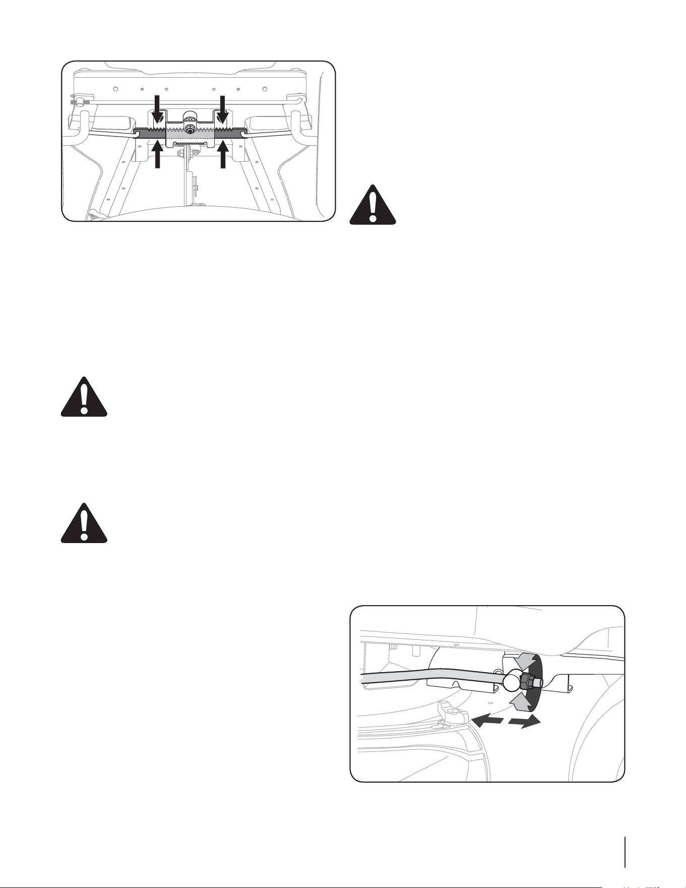
Nettoyage de la batterie
(BSEF[MFTCPSOFTFUMFEFTTVTEFMBCBUUFSJFQSPQSFTFUÏWJUF[
toute corrosion. Nettoyez la batterie avec du bicarbonate de
TPVEFFUEFMFBV"VCFTPJOHSBUUF[MFTCPSOFTEFMBCBUUFSJF
avec une brosse métallique pour déloger les saletés. Enduisez les
CPSOFTFUMFTGJMTFYQPTÏTBWFDEFMBHSBJTTFPVEFMBWBTFMJOFQPVS
empêcher toute corrosion.
Réglages
AVERTISSEMENT /FTTBZF[KBNBJTEFGGFDUVFS
un réglage quelconque pendant que le moteur
tourne, à moins d’indications contraires dans la
notice d’utilisation.
Mise à niveau du plateau de coupe
REMARQUE: Vérifiez la pression des pneus du tracteur avant de
SÏHMFSMFQMBUFBVEFDPVQF$POTVMUF[MBTFDUJPO1OFVTEBOTMF
chapitre «Entretien» de cette notice d’utilisation pour plus de
renseignements concernant la pression des pneus.
Réglage d’avant à arrière
L’avant du plateau de coupe est soutenu par une barre de stabilisation
réglable permettant d’ajuster le plateau de l’avant à l’arrière. L’avant du
QMBUFBVEFDPVQFEPJUTFUSPVWFSFOUSFFUFTEFQPQMVTCBTRVF
l’arrière. Réglez selon le besoin comme suit:
1. Stationnez le tracteur sur une surface stable et plane et
QPTJUJPOOF[MBNBOFUUFEFSFMFWBHFEBOTMBEFVYJÒNF
position la plus haute. Tournez la lame le plus près possible
de la goulotte d’éjection parallèle au tracteur.
2. .FTVSF[MBEJTUBODFEFMFYUSÏNJUÏBWBOUEFMBMBNFBVTPMFU
MFYUSÏNJUÏBSSJÒSFEFMBMBNFBVTPM-FQSFNJFSSFMFWÏEPJU
NFTVSFSEFËFTEFQPEFNPJOTRVFMFEFVYJÒNF
%ÏUFSNJOF[MBEJTUBODFBQQSPYJNBUJWFOÏDFTTBJSFQPVSVO
bon ajustement, puis passez à l’étape suivante si besoin est.
3. Repérez l’écrou sur l’avant du support de stabilisation. Voir
la Figure 6-3.
t Serrez l’écrou pour relever l’avant du plateau de
coupe.
t Desserrez l’écrou pour abaisser l’avant du plateau de
coupe.
Nettoyage du moteur et du plateau de coupe
Essuyez immédiatement toutes les éclaboussures d’huile
ou d’essence. Ne laissez pas l’herbe, les feuilles et la saleté
TBDDVNVMFSËQSPYJNJUÏEFTBJMFUUFTEFSFGSPJEJTTFNFOUEV
moteur ou sur toute autre partie de la machine.
IMPORTANT: L’utilisation d’un nettoyeur sous pression ou d’un
boyau d’arrosage pour nettoyer le tracteur est déconseillée. Cela
risque en effet d’endommager les composants électriques, les
fusées, les poulies, les roulements ou le moteur.
AVERTISSEMENT -BDDVNVMBUJPOEFEÏCSJTË
QSPYJNJUÏEVTJMFODJFVYQFVUDBVTFSVOJODFOEJF
*OTQFDUF[FUOFUUPZF[DFUUF[POFBWBOUDIBRVF
emploi.
Silencieux
N’utilisez pas d’eau pour nettoyer les pièces du moteur. L’eau
risque de contaminer le carburant. Utilisez une brosse ou un
linge sec.
AVERTISSEMENT *OTQFDUF[SÏHVMJÒSFNFOUMF
TJMFODJFVYFUSFNQMBDF[MFTJCFTPJOFTU-FTQJÒDFT
EFSFDIBOHFEVTJMFODJFVYEPJWFOUÐUSFJEFOUJRVFTFU
installées de la même façon que les pièces d’origine.
Batterie
-BCBUUFSJFFTUTDFMMÏFFUOFOÏDFTTJUFBVDVOFOUSFUJFO*MOFTUQBT
possible de vérifier le niveau de l’acide.
t Vérifiez que les câbles et bornes de la batterie sont toujours
propres et ne sont pas corrodés.
t "QSÒTBWPJSOFUUPZÏMBCBUUFSJFFUMFTCPSOFTBQQMJRVF[VOF
légère couche de vaseline ou de graisse sur les bornes et
sur la gaine de la borne positive.
t "TTVSF[WPVTRVFMBHBJOFFTUUPVKPVSTCJFOQMBDÏFTVSMB
borne positive pour éviter tout court-circuit.
IMPORTANT: Si, pour une raison quelconque, il est nécessaire
EFEÏNPOUFSMBCBUUFSJFEÏCSBODIF[UPVKPVSTMFDÉCMF/²("5*'
OPJSEFMBCPSOFOÏHBUJWFQVJTMFDÉCMF104*5*'SPVHF-PST
EVSFNPOUBHFEFMBCBUUFSJFCSBODIF[UPVKPVSTMFDÉCMF104*5*'
SPVHFTVSMBCPSOFQPTJUJWFQVJTMFDÉCMF/²("5*'OPJS7ÏSJGJF[
que les câbles sont branchés sur les bornes correspondantes.
Leur inversion peut changer la polarité et endommager
l’alternateur du moteur.
Figure 6-2
Figure 6-3
21SECTION 6 — ENTRETIEN & RÉGLAGES

Réglage du siège
1PVSBKVTUFSMBQPTJUJPOEVTJÒHFDPOTVMUF[MFDIBQJUSFj.POUBHF
du tracteur».
Réglage du frein
AVERTISSEMENT : N’essayez jamais d’ajuster les
GSFJOTQFOEBOURVFMFNPUFVSUPVSOF"SSÐUF[
toujours les lames et la prise de force, placez le
sélecteur de vitesse au point mort, arrêtez le moteur
et retirez la clé avant pour empêcher tout
démarrage non intentionnel.
Si le tracteur ne s’immobilise pas complètement quand la pédale
de frein est enfoncée, ou si les roues arrière du tracteur peuvent
tourner alors que le frein de stationnement est serré, il faudra
BKVTUFSMFGSFJO"ESFTTF[WPVTËVOFTUBUJPOUFDIOJRVFBHSÏÏF
pour faire ajuster les freins correctement.
Pneus
AVERTISSEMENT : Ne dépassez jamais la
QSFTTJPOEFHPOGMBHFNBYJNBMFJOEJRVÏFTVSMFGMBOD
du pneu.
La pression des pneus recommandée pour le travail est de :
t 10 lb/po2 environ pour les pneus arrière.
t MCQPFOWJSPOQPVSMFTQOFVTBWBOU
IMPORTANT: La pression recommandée par le fabricant est
JOEJRVÏFTVSMFGMBODEFTQOFVT/FHPOGMF[QBTFYDFTTJWFNFOUMFT
pneus. Une pression inégale peut causer la tonte inégale de l’herbe.
Préparation du moteur
AVERTISSEMENT : Ne remisez jamais la machine
ou un contenant de carburant à l’intérieur en
présence d’une flamme nue, d’étincelles ou d’une
veilleuse comme celle d’un chauffe-d’eau, d’un
calorifère, d’un sêche-linge ou d’un autre appareil à
gaz.
IMPORTANT: Tout carburant restant dans le réservoir par temps
chaud risque de se détériorer et de causer des problèmes au
démarrage.
1PVSÏWJUFSMBGPSNBUJPOEFEÏQÙUTHPNNFVYEBOTMFDBSCVSBUFVS
et le mauvais fonctionnement possible du moteur, il est
nécessaire de purger complètement le système d’alimentation
du tracteur ou de traiter l’essence en ajoutant un produit de
stabilisation qui empêchera sa détérioration.
1. Si vous décidez d’ajouter un produit de stabilisation:
a. Lisez attentivement les instructions et
recommandations du fabricant du produit.
b. "KPVUF[MBRVBOUJUÏBQQSPQSJÏFEFQSPEVJUEF
stabilisation à une essence propre et fraîche
correspondant à la capacité du moteur.
c. Faites le plein avec l’essence traitée et laissez tourner
le moteur pendant 2 à 3 minutes pour que le produit
de stabilisation atteigne le carburateur.
2. Si vous choisissez de purger le système d’alimentation:
a. Ne purgez pas le système quand le moteur est
chaud. Laissez le moteur refroidir. Videz le carburant
EBOTVODPOUFOBOUIPNPMPHVÏËMFYUÏSJFVSMPJOEF
toute flamme nue.
b. Videz toute quantité importante de carburant du
réservoir en débranchant le filtre d’arrivée près du
moteur. Voir les instructions complètes concernant
la vidange du carburant plus loin dans ce chapitre.
AVERTISSEMENT : L’essence est un produit
IBVUFNFOUJOGMBNNBCMFRVJQFVUFYQMPTFSEBOT
certaines conditions. Videz toute l’essence avant de
remiser l’équipement pour une période prolongée.
Utilisez seulement un contenant homologué et
USBWBJMMF[ËMFYUÏSJFVSMPJOEFUPVUFGMBNNFOVF
Laissez le moteur refroidir. Éteignez les cigarettes,
pipes ou cigares et autre source d’allumage avant
de vider le réservoir d’essence. Entreposez l’essence
dans un contenant homologué et dans un endroit
sécuritaire.
c. Rebranchez la conduite d’essence et faites tourner le
moteur jusqu’à ce qu’il commence à hésiter. Utilisez
ensuite le volet de départ pour que le moteur
continue à tourner jusqu’à ce qu’il tombe en panne
d’essence.
d. Débranchez la conduite d’essence et purgez toute
l’essence restant dans le système d’alimentation.
AVERTISSEMENT : L’essence est un produit
UPYJRVF²MJNJOF[MFTTFODFEFMBNBOJÒSFBQQSPQSJÏF
Renseignez-vous auprès des autoritéslocales quant
BVYNÏUIPEFTEÏMJNJOBUJPOBQQSPVWÏFT
3. Démontez la bougie et versez une once d’huile à
moteur dans le cylindre par le trou de la bougie. Tournez
manuellement le moteur plusieurs fois pour bien répartir
l’huile. Remettez la bougie en place.
Vidange du carburant:
5. Localisez le filtre à essence qui se trouve sur la gauche
du moteur, entre le réservoir d’essence et le carburateur.
*MQFVUÐUSFNBJOUFOVTVSMFNPUFVSBWFDVOFDPVSSPJF
d’attache.
6. Coupez la courroie d’attache le cas échéant, puis serrez le
collier de l’arrivée du filtre à essence avec une pince. Faites
remonter le collier sur la conduite d’essence.
Dégagez la conduite d’essence du filtre et placez son
FYUSÏNJUÏPVWFSUFEBOTVOSÏDJQJFOUIPNPMPHVÏQPVSZ
recueillir le carburant.
Préparation du tracteur de pelouse
1. Nettoyez et lubrifiez le tracteur selon les instructions de
lubrification.
2. N’utilisez pas un nettoyeur sous pression ou un boyau
d’arrosage pour nettoyer le tracteur.
3. Entreposez le tracteur dans un endroit propre et sec. Ne le
SFNJTF[QBTQSÒTEFNBUÏSJBVYDPSSPTJGTDPNNFEFTFOHSBJT
QBSFYFNQMF
22 SECTION 6— ENTRETIEN & RÉGLAGES

Calendrier des opérations d’entretien
Avant l’emploi
Toutes les 10
heures
Toutes les 25
heures
Toutes les 50
heures
Toutes les 100
heures
Avant le
remisage
Vérication du niveau de l’huile à moteur
33 3
Vérication de la prise d’air
et nettoyage éventue
3
Nettoyage et lubrication éventuelle
de la cartouche en mousse du ltre à air
3
Remplacement du ltre à air
3
Vidange de l’huile à moteur et du ltre à huile
3
Nettoyage des bornes de la batterie
33
Lubrication d’essieus et jantes avant
33
Vérication des ailettes de refroidissement du
moteur
33
Vérication des bougies et l’écartement
33
Remplacez le ltre de carburant
3
IMPORTANT: *MFTUJNQPSUBOUEFDPOTVMUFSMBOPUJDFEVUJMJTBUJPOTQÏDJGJRVFËWPUSFNPUFVSRVJBDDPNQBHOFMBNBDIJOFQPVSPCUFOJS
une description détaillée des procédures et intervalles d’entretien.
23SECTION 6 — ENTRETIEN & RÉGLAGES
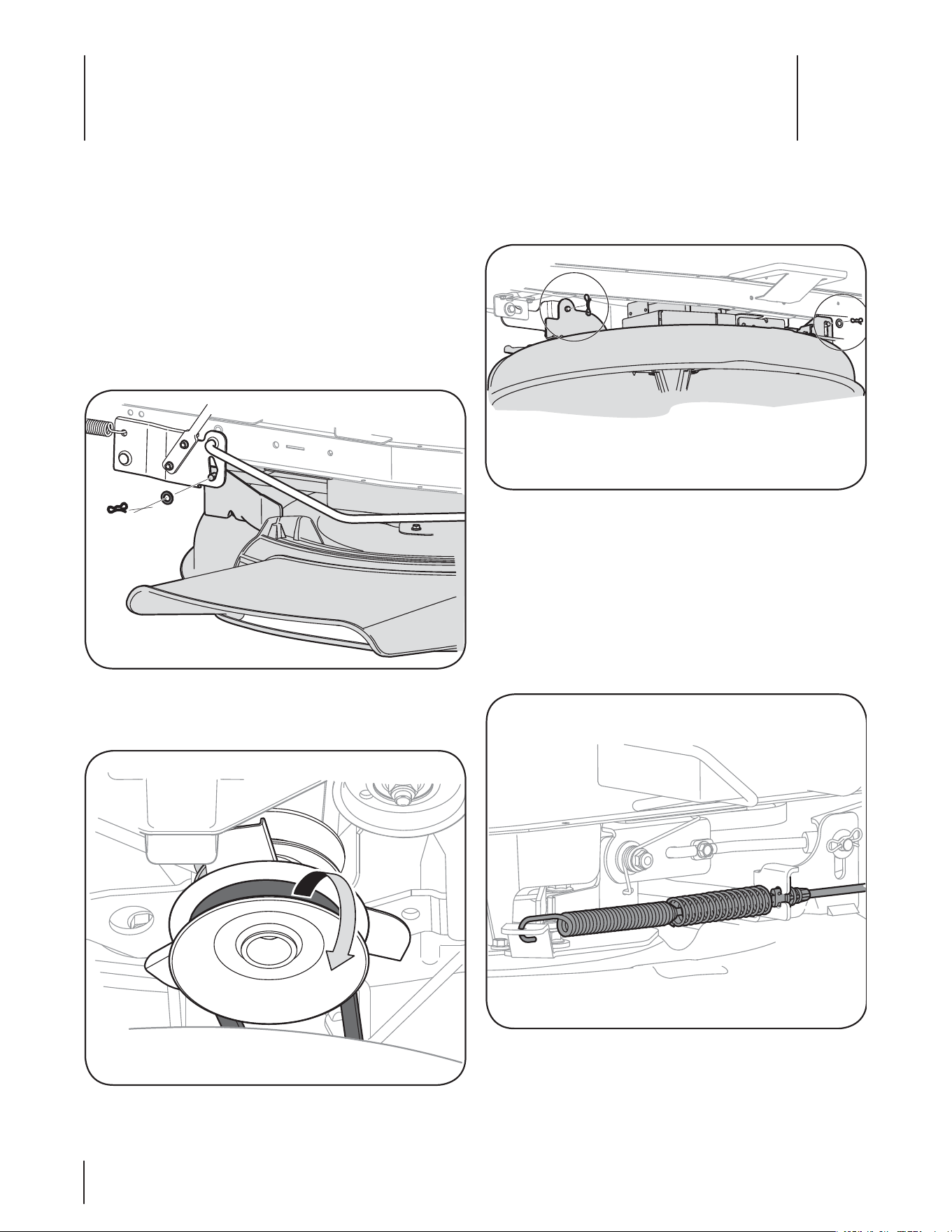
Service
7
24
Service
7
24
5. Enlevez les goupilles papillon qui maintiennent le plateau
EFDPVQFTVSMFUSBDUFVSDPNNFËMB'JHVSF
REMARQUE : Les goupilles papillon doivent être remises
en place du haut vers le bas.
6. Débranchez le fil en queue de cochon du commutateur du
plateau de coupe.
1MBDF[MBNBOFUUFEFSFMFWBHFEVQMBUFBVEFDPVQFEBOT
l’encoche supérieure sur l’aile droite pour relever les bielles
de relevage du plateau de coupe et les écarter.
8. Écartez le câble de la prise de force de l’arrière du plateau
de coupe en retirant la goupille-épingle qui le retient.
Retirez le ressort du support de la poulie de tension du
QMBUFBVEFDPVQF7PJSMB'JHVSF
%ÏHBHF[MFQMBUFBVEFDPVQFTVSMFDÙUÏHBVDIFEV
dessous du tracteur.
Démontage du plateau de coupe
1PVSEÏNPOUFSMFQMBUFBVEFDPVQFQSPDÏEF[DPNNFTVJU
1. 1MBDF[MBNBOFUUFEFMBQSJTFEFGPSDF&NCSBZBHFEFMB
MBNFËMBQPTJUJPOj0''x/POFNCSBZÏF4FSSF[MFGSFJO
de stationnement.
2. "CBJTTF[MFQMBUFBVEFDPVQFFOQMBÎBOUMBNBOFUUFEF
relevage du plateau dans l’encoche inférieure sur le garde-
boue de droite.
3. Enlevez la goupille papillon et la rondelle plate de
l’ensemble de relevage du plateau de coupe et gardez-les
QPVSMFTVUJMJTFSQMVTUBSE7PJSMB'JHVSF
Dégagez la courroie de la prise de force de la poulie
NPUSJDFEVUSBDUFVS7PJSMB'JHVSF
Figure 7-4
Figure 7-1
Figure 7-2
Figure 7-3
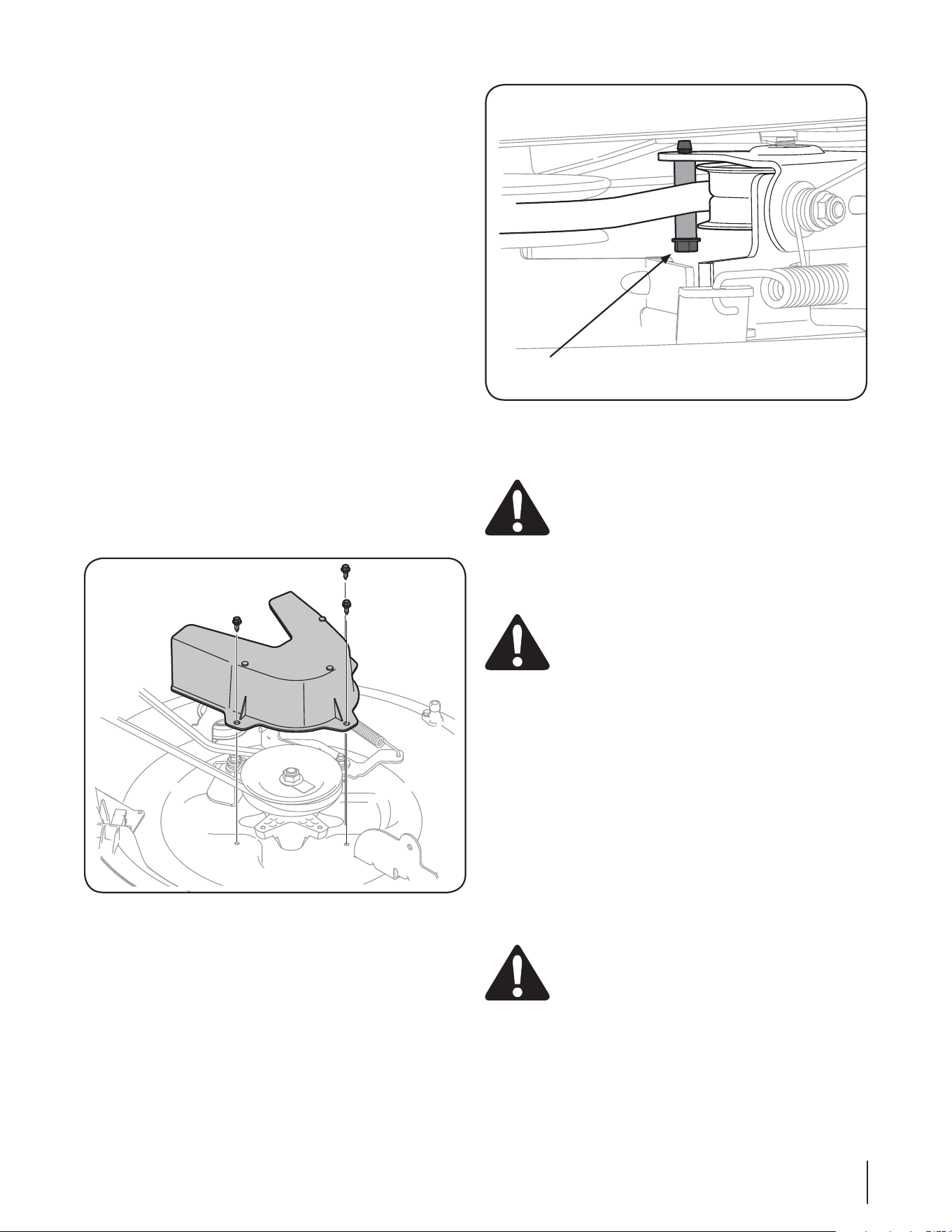
25SECTION 7 — SERVICE 25SECTION 7 — SERVICE
Remplacement de
la courroie du plateau de coupe
REMARQUE *MFTUQPTTJCMFEFSFNQMBDFSMBDPVSSPJFEVQMBUFBV
de coupe sans démonter celui-ci. Toutefois, il est plus facile de
démonter le plateau de coupe, de changer la courroie, puis de
remonter le plateau de coupe.
Procédez comme suit pour remplacer la courroie du plateau de
coupe:
1. *MFTUQMVTGBDJMFEFSFNQMBDFSMBDPVSSPJFBQSÒTBWPJS
d’abord démonté le plateau de coupe selon les instructions
précédentes.
2. Si vous changez la courroie avec le plateau de coupe en
place, abaisser le tablier à la position la plus basse tonte.
3. Dégagez la courroie de la poulie d’entraînement de la p. d.
GDPNNFËMB'JHVSF3PVMF[VODÙUÏEFMBDPVSSPJFQPVS
la dégager de la poulie, puis continuez jusqu’à ce qu’elle
soit complètement dégagée de la poulie.
Tirez la courroie vers l’arrière du tracteur et dégagez-la du
TVQQPSUEVHVJEFEFMBDPVSSPJF7PJSMB'JH
5. &OMFWF[MFDPVWSFDPVSSPJFFOSFUJSBOUMFTUSPJTCPVMPOTIFY
RVJMFSFUJFOOFOU7PJSMB'JH
6. %ÏNPOUF[MBQPVMJFEFUFOTJPOFOFOMFWBOUMFCPVMPOIFY
TVSMBCBTFEFMBQPVMJF7PJSMB'JH
Remplacez la courroie, puis remontez dans l’ordre inverse
toutes les pièces enlevées précédemment, en commençant
par la poulie de tension, puis le couvre-courroie.
8. Faites passer la courroie du plateau de coupe dans
le support du guide de courroie, puis sur la poulie
EFOUSBÔOFNFOUEFMBQEGDPNNFËMB'JH
Batterie
PROPOSITION 86 – Californie!
AVERTISSEMENT : Les bornes et cosses de batterie
FUEBVUSFTBDDFTTPJSFTBOOFYFTDPOUJFOOFOUEV
plomb et des mélanges à base de plomb, soit des
produits chimiques reconnus cancérigènes et
responsables d’anomalies congénitales ou autres
QBSM²UBUEF$BMJGPSOJF*MFTUJNQÏSBUJGEFCJFOTF
laver les mains après toute manutention.
IMPORTANT: Si, pour une raison quelconque, il
est nécessaire de démonter la batterie, débranchez
UPVKPVSTMFDÉCMF/²("5*'OPJSEFMBCPSOF
OÏHBUJWFQVJTMFDÉCMF104*5*'SPVHF-PSTEV
remontage de la batterie, branchez toujours le câble
104*5*'SPVHFTVSMBCPSOFQPTJUJWFQVJTMFDÉCMF
/²("5*'OPJS
Pannes de la batterie
1BSNJMFTDBVTFTDPVSBOUFTEFQBOOFTEFCBUUFSJFOPUPOT
t la mise en service initiale incorrecte
t VOFDIBSHFFYDFTTJWF
t le gel
t une charge insuffisante
t des raccords corrodés
Ces pannes ne sont pas couvertes par la garantie.
Démarrage par câbles volants
AVERTISSEMENT! Ne faites jamais démarrer une
batterie endommagée ou gelée en utilisant des
DÉCMFTWPMBOUT"TTVSF[WPVTRVFMFTWÏIJDVMFTOFTF
touchent pas et que le moteur de chaque véhicule
est arrêté. Faites attention que les pinces des câbles
ne se touchent pas.
1. #SBODIF[MFDÉCMFQPTJUJGTVSMBCPSOFQPTJUJWFEFMB
batterie à plat du tracteur.
2. #SBODIF[MBVUSFFYUSÏNJUÏEVDÉCMFQPTJUJGTVSMBCPSOF
QPTJUJWFEFMBCBUUFSJFEBQQPJOU
Figure 7-5
Figure 7-6
Boulon hex.
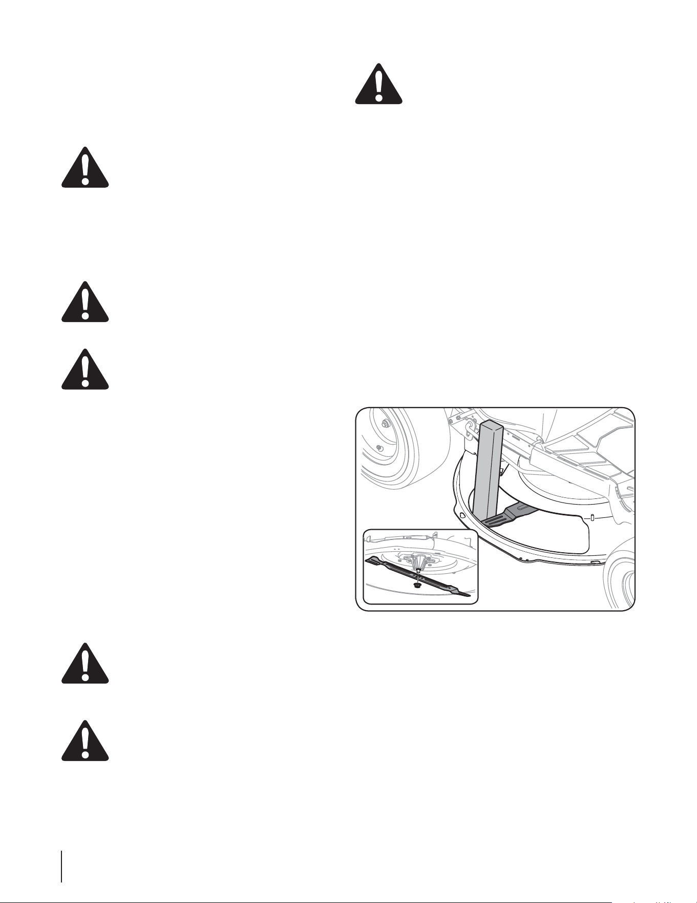
26 SECTION 7— SERVICE26 SECTION 7— SERVICE
3. #SBODIF[MFDÉCMFOÏHBUJGTVSMBVUSFCPSOFEFMBCBUUFSJF
d’appoint.
'JOBMFNFOUCSBODIF[MBVUSFFYUSÏNJUÏEVDÉCMFOÏHBUJG
sur le bloc moteur du tracteur, à l’écart de la batterie.
Choisissez un endroit non peint pour obtenir un bon
contact.
ATTENTION : Si la batterie d’appoint est installée
TVSVOWÏIJDVMFWPJUVSFDBNJPOOFNFUUF[QBTMF
moteur du véhicule en marche pour faire démarrer
le tracteur.
5. Mettez le tracteur en marche (en suivant les instructions du
chapitre «Fonctionnement» dans cette notice d’utilisation.
6. Serrez le frein de stationnement avant de retirer les câbles
volants dans l’ordre inverse de leur branchement.
Charge de la batterie
AVERTISSEMENT: Les batteries déga-gent des
HB[FYQMPTJGTQFOEBOUMFVSNJTFFODIBSHFFUBQSÒT
Chargez toujours les batteries dans un endroit bien
aéré et ne produisez pas d’étincelles ni de flammes à
QSPYJNJUÏ
ATTENTION 1PVSDIBSHFSMBCBUUFSJFEVUSBDUFVS
utilisez seulement un chargeur conçu pour des
batteries à accumulateur plomb-acide de 12 volts.
Veuillez lire la notice d’utilisation du chargeur de la
batterie avant de charger la batterie. Suivez toujours
les instructions et respectez les avertissements.
Si le tracteur n’a pas été utilisé pendant une période prolongée,
chargez la batterie comme suit:
1. 3ÏHMF[MFDIBSHFVSËVOFDIBSHFNBYEFBNQÒSFT
Si le chargeur de la batterie est automatique, chargez la batterie
jusqu’à ce que le chargeur indique que la charge est terminée. S’il
n’est pas automatique, chargez la batterie pendant un minimum
de huit heures.
Fusibles
6OGVTJCMFEF"FTUJOTUBMMÏEBOTMFGBJTDFBVEFGJMTEVUSBDUFVS
pour protéger le système électrique du tracteur des dégâts
causés par un ampérage trop élevé.
Si le système électrique ne fonctionne pas, ou si le moteur ne
tourne pas, vérifiez d’abord que le fusible n’a pas sauté. Le fusible
est installé sous le capot, derrière le haut du panneau de bord sur
le barre de support.
AVERTISSEMENT: Remplacez toujours le fusible
par un fusible de même ampérage.
Lames
AVERTISSEMENT "SSÐUF[MFNPUFVSFOMFWF[MB
clé d’allumage avant de démonter les lames pour les
BJHVJTFSPVMFTSFNQMBDFS1PSUF[UPVKPVSTEFTHBOUT
épais ou utilisez un chiffon pour manipuler les
lames.
AVERTISSEMENT &YBNJOF[SÏHVMJÒSFNFOUMFT
fusées pour vous assurer qu’ils ne sont pas fendillés
ou endommagés, surtout après avoir heurté un
objet quelconque. Remplacez-les immédiatement
s’ils sont endommagés.
Démontez les lames de la façon suivante:
REMARQUE *MTFSBQMVTGBDJMFEFDIBOHFSMBMBNFBQSÒTBWPJS
démonté le plateau de coupe du dessous du tracteur. (Consultez
MBTFDUJPOj%ÏNPOUBHFEVQMBUFBVEFDPVQFxEBOTDFDIBQJUSF
QVJTCBTDVMF[EPVDFNFOUMFQMBUFBVEFDPVQFQPVSFYQPTFS
MFEFTTPVT*MFTUUPVUFGPJTQPTTJCMFEFDIBOHFSMBMBNFTBOT
démonter le plateau de coupe. Dans ce cas, placez la manette
de relevage du plateau de coupe à la position de coupe la plus
haute.
1. Enlevez le bouchon de déchiquetage ou le sac à herbe,
MFDBTÏDIÏBOUQPVSFYQPTFSMPVWFSUVSFEFMBHPVMPUUFEV
plateau de coupe. Si le plateau de coupe est équipé d’une
goulotte, pivotez simplement la goulotte à ressort pour
accéder à l’ouverture.
2. *OTÏSF[VOFDBMFFOCPJTPVVONPSDFBVEFQPVUSFEFY
po dans l’ouverture du plateau de coupe et faites tourner
la lame jusqu’à ce que la cale se coince entre l’ouverture du
QMBUFBVEFDPVQFFUMBMBNFDPNNFËMB'JH
3. 3FUJSFSMÏDSPVËCSJEFËTJYQBOTRVJNBJOUJFOUMBMBNF7PJSMB
'JHVSF
REMARQUE: La fusée du plateau de coupe est munie d’un
GJMFUOPSNBM1PVSMBEFTTFSSFSUPVSOF[MFDPOUSFÏDSPVË
FNCBTFEBOTMFTFOTDPOUSBJSFBVYBJHVJMMFTEVOFNPOUSF
Figure 7-7
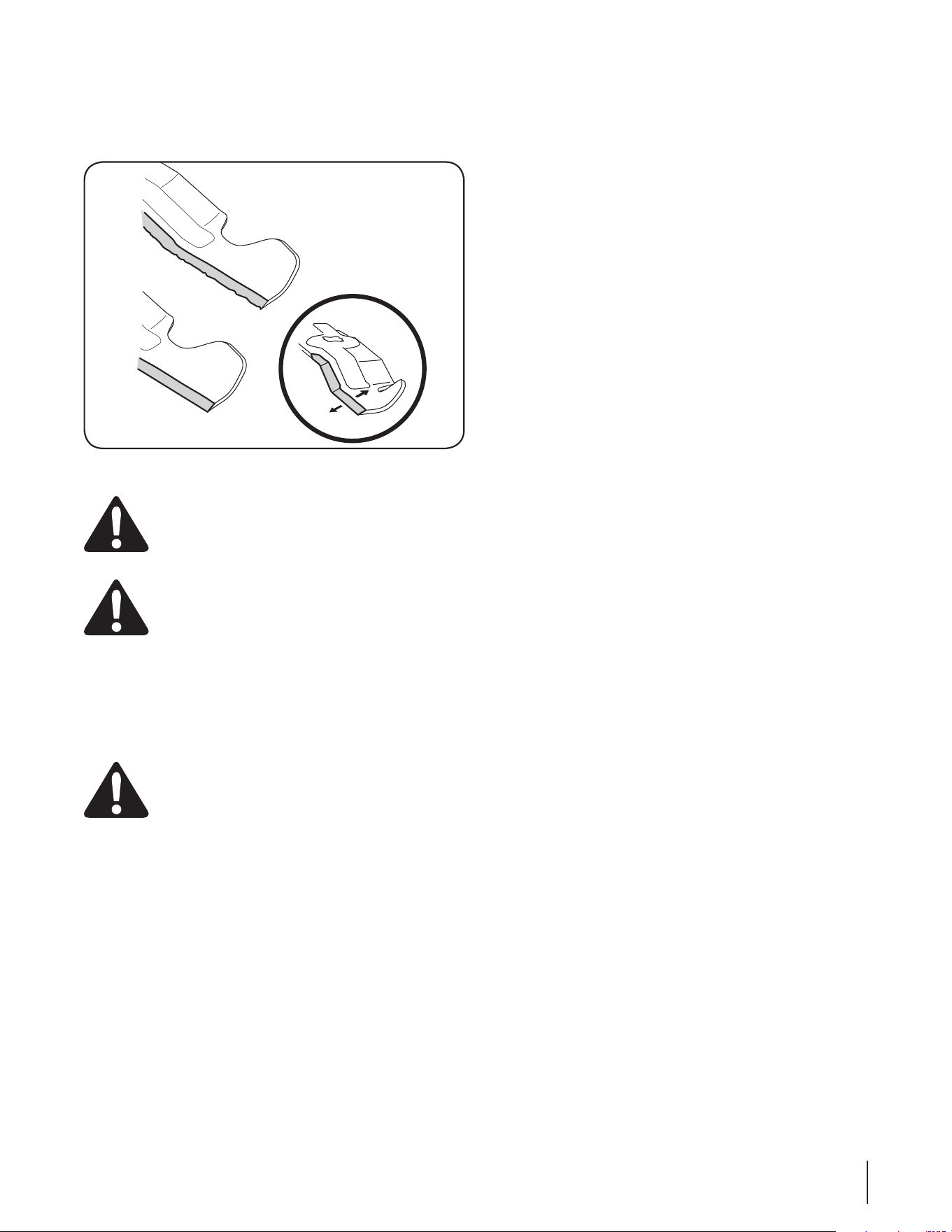
27SECTION 7 — SERVICE 27SECTION 7 — SERVICE
4. Pour aiguiser les lames, la même quantité de métal des deux
extrémités des lames sur le côté tranchant. Aiguisez le bord
tranchant sur toute sa longueur, parallèlement au bord
arrière, soit à un angle de 25° à 30°. Voir la Figure 7-8.
AVERTISSEMENT ! Si le bord tranchant a déjà été
aiguisé, ou si une séparation des couches
métalliques s’est produite, remplacez les lames.
AVERTISSEMENT ! En effet, une lame
déséquilibrée risque de vibrer excessivement à
vitesse élevée. Ceci peut endommager le tracteur et
causer des blessures.
5. Vérifier l’équilibre de la lame avec l’aide d’un balancer
de lame. Meuler du métal du côté lourd jusqu’à ce qu’il
équilibre également.
REMARQUE: Faites attention, en remplaçant la lame, de tourner
le côté «Bottom» (ou sur lequel un numéro de pièce est estampé)
vers le sol quand la machine est utilisée.
IMPORTANT: Utilisez une clé dynamométrique
pour serrer l’écrou à bride à six pans sur la fusée de
la lame à un couple de 70 pieds-livre à 90 pieds-livre.
Changement de la courroie de transmission
REMARQUE: Certaines pièces doivent être retirées et des outils
spéciaux (clé pneumatique) doivent être utilisés pour remplacer
les courroies de transmission du tracteur. Adressez-vous à une
station technique agréée pour faire remplacer les courroies de
transmission ou contactez le service après-vente comme instruit
à la page 2.
Figure 7-8

Problème Cause Solution
Le moteur ne
tourne pas
1. Manette de la prise de force est enclenchée.
2. Fil de la bougie desserré.
3. Réservoir de carburant est vide ou essence
éventée.
Volet de départ non activé.
5. Bougie défectueuse.
6. Le fusible a sauté.
Canalisation de carburant bouchée.
8. Frein de stationnement déclenché.
(PVMPUUFEÏKFDUJPOCPVDIPOEFEÏDIJRVFUBHFPV
le tube goulotte pas correctement installé.
1. 1MBDF[MBNBOFUUFEFMBQSJTFEFGPSDFËMBQPTJUJPO
0''EÏDMFODIÏF
2. Branchez le fil de la bougie.
3. Faites le plein avec une essence propre et fraîche.
1MBDF[MBWPMFUEFEÏQBSUËMBQPTJUJPO70-&5%&
%²1"35
5. Enclenchez le frein de stationnement.
6. Remplacer le fusible.
Nettoyez, réglez l’écartement ou remplacez la
bougie.
8. Serrer le frein de stationnement.
Vérifier l’installation de la goulotte d’éjection,
bouchon de déchiquetage ou le tube goulotte.
Fonctionnement irrégulier 1. Machine fonctionnant avec volet de départ fermé.
2. Fil de la bougie desserré.
3. Canalisation de carburant bouchée ou
essence éventée.
L’évent du capuchon du réservoir est bouché.
5. Eau ou saleté dans le système d’essence.
6. Filtre à air est sale.
1. 1MBDF[MBNBOFUUFEFDPNNBOEFEFMPCUVSBUFVSË
MBQPTJUJPO'"45SBQJEF
2. Branchez et serrez le fil de la bougie.
3. Nettoyez la canalisation ; faites le plein avec une
essence propre. Remplacez le filtre de carburant
TJÏRVJQÏ
Débouchez l’évent ou remplacez le capuchon.
5. Débranchez la canalisation d’essence au
carburateur pour vider le réservoir d’essence.
Faites le plein avec une essence fraîche.
6. Remplacez le filtre à air ou le pré-nettoyeur.
Moteur surchauffe 1. Niveau d’huile est est trop bas.
2. La circulation d’air est gênée.
1. Faites le plein d’huile du carter.
2. Essuyez les brins d’herbe et débris autour des
ailerons refroidissant du moteur et de l’habitacle
du ventilateur.
Moteur hésite
à vitesse élevée
1. Écartement de la bougie trop petit. 1. Retirez la bougie et réglez l’écartement.
Le moteur tourne
irrégulièrement
1. La bougie est sale, défectueuse ou l’écartement
est trop grand.
2. Filtre à air est sale.
1. Remplacez la bougie. Réglez l’écartement.
2. Remplacez le filtre à air ou le pré-nettoyeur (si
ÏRVJQÏ
Vibrations
FYDFTTJWFT
1. La lame de coupe est desserrée ou déséquilibrée.
2. La lame est endommagée ou déformée.
1. Serrez la lame et la fusée. Équilibrez la lame.
2. Remplacez la lame.
La tondeuse ne déchiquette
pas
l’herbe
MFDBTÏDIÏBOU
1. Vitesse du moteur trop bas.
2. L’herbe est mouillé.
3. L’herbe est trop haute.
La lame est émoussée.
1. 1MBDF[MPCUVSBUFVSËMBQPTJUJPO'"45SBQJEF
2. /FUPOEF[QBTRVBOEMIFSCFFTUNPVJMMÏ"UUFOEF[
qu’elle sêche.
3. Coupez l’herbe à un réglage élevé, puis tondez à
nouveau à la hauteur voulue ou sur une largeur
plus étroite.
"JHVJTF[PVSFNQMBDF[MBMBNF
La coupe est
irrégulière
1. 1MBUFBVEFDPVQFOPOÏRVJMJCSÏDPSSFDUFNFOU
2. La lame est émoussée.
3. 1SFTTJPOJOÏHBMFEFQOFV
1. Faites le réglage latéral du plateau de coupe.
2. "JHVJTF[PVSFNQMBDF[MBMBNF
3. Vérifiez la pression de pneu dans chacun des
quatre pneus.
Depannage
8
28

-FTBDDFTTPJSFTFUÏRVJQFNFOUBOOFYFTVJWBOUTQFVWFOUÐUSFJOTUBMMÏTTVSMFUSBDUFVS"ESFTTF[WPVTBVDPODFTTJPOOBJSFPVBV
DPODFTTJPOOBJSFDIF[MFRVFMWPVTBWF[BDIFUÏMFUSBDUFVSQPVSUPVUSFOTFJHOFNFOUDPODFSOBOUMFTQSJYFUMBEJTQPOJCJMJUÏEFT
accessoires.
ATTENTION : Le tracteur ne sont pas conçus pour être utilisés avec des accessoires de travail de la terre (motoculteur
PVDIBSSVFQBSFYMFNQMPJEFDFHFOSFEBDDFTTPJSFTSFOESBMBHBSBOUJFOVMMFFUOPOBWFOVF
Numéro de modèle Description
"0&. $PMMFDUFVSEIFSCFËEFVYTBDT
"0&. Ensemble de déchiquetage
Accessoires et Équipement Annexe
9
29
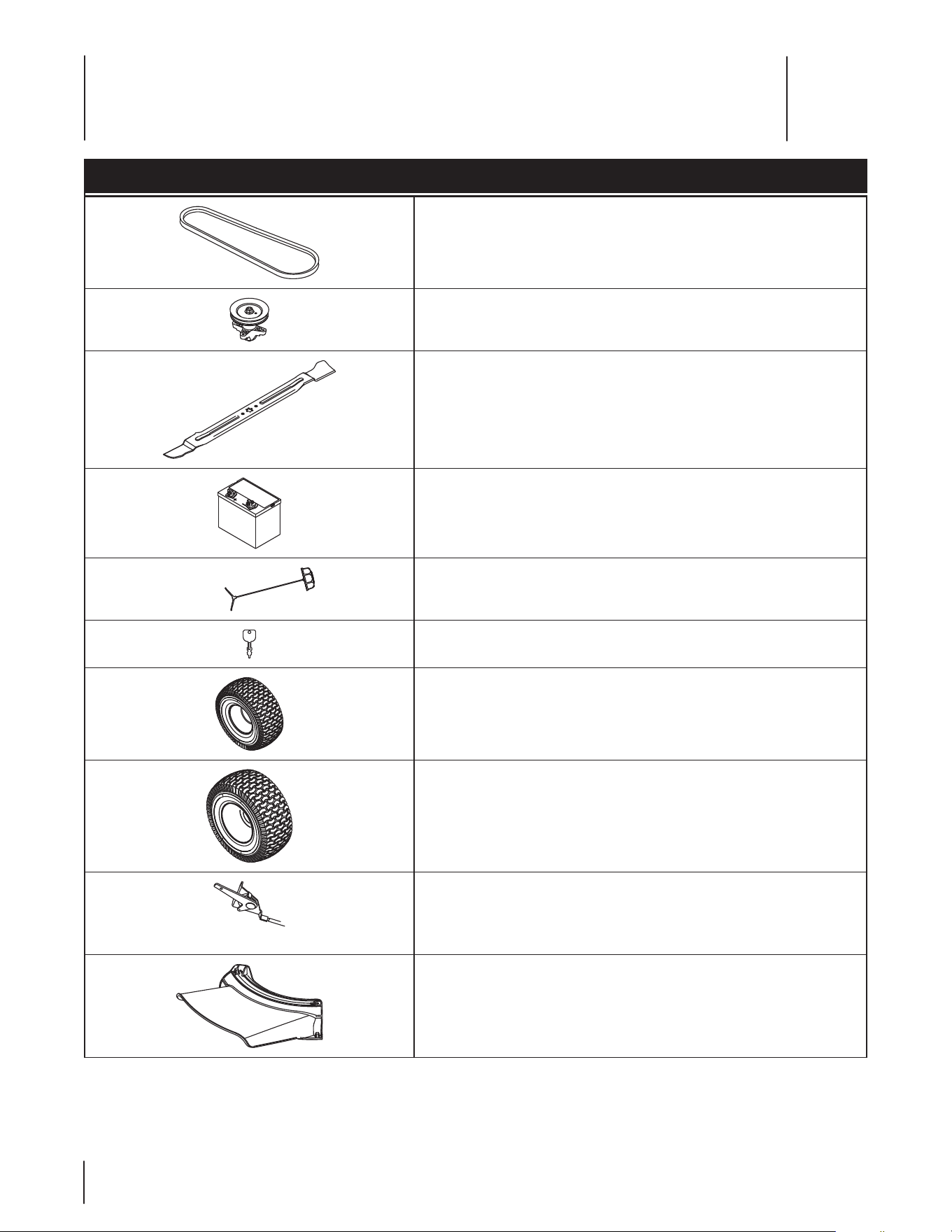
Component No. de pièce et description
Courroie d’entraînement (plateau de coupe)
918-04822A Fusée
942-04385 Lames (30 po)
% #BUUFSJF
751-12179A Capuchon d’essence
" $MÏ
&OTFNCMFEFSPVFDPNQMFUF"WBOUYYQP
1OFVTFVMFNFOU"WBOUYYQP
&OTFNCMFEFSPVFDPNQMFUF (Arrrière) 16 x 6,5 x 8 po
1OFVTFVMFNFOU"SSSJÒSFYYQP
" Câble de commande de l’obturateur
731-09357 Déflecteur complet
REMARQUE: Vous pouvez télécharger un livret contenant la liste complète des pièces détachées en visitant www.mtdcanada.ca ou
FOUÏMÏQIPOBOUBVQPVSFOBDIFUFSVO1SÏQBSF[MFOVNÏSPEFNPEÒMFFUMFOVNÏSPEFTÏSJFEFWPUSFNBDIJOF7PVT
les trouverez sur la plaque signalétique qui se trouve sous le siège. Voir les renseignements qui se trouvent à la page 2 pour localiser
les numéros de modèle et de série de votre machine.
Pièces de rechange
30
10

Notes
31

32
Déclaration de garantie du système antipollution en Californie
Droits et obligations du propriétaire en vertu de la garantie
C’est avec plaisir que California Air Resources Board (CARB), la United States Environmental Protection Agency et MTD Consumer
Group Inc. Consumer Group Inc. présentent la garantie du système antipollution installé sur vos moteur et équipement hors route
construits en 2008. En Californie, les moteurs et l’équipement hors route neufs doivent être conçus, construits et équipés conformé-
ment aux normes antipollution strictes de l’état. (Ailleurs aux Etats-Unis, les moteurs et l’équipement hors route neufs à allumage
par étincelle des années 1997 et ultérieures doivent respecter des normes similaires établies par U. S. EPA). MTD Consumer Group Inc.
Consumer Group Inc. doit garantir le système antipollution du moteur pour la durée stipulée ci-dessous, à condition que le moteur et
l’équipement hors route n’aient pas fait l’objet d’abus, de négligence ou d’un entretien incorrect.
Le système antipollution peut inclure les pièces suivantes : carburateur, système d’injection du carburant, système d’allumage,
pot catalytique, réservoirs, canalisations et bouchons d’essence, soupapes, cartouches absorbantes des vapeurs d’essence, filtres,
canalisations, colliers, raccords et autres pièces annexes du système antipollution.
MTD Consumer Group Inc s’engage à réparer gratuitement votre machine, y compris les frais de diagnostic, les pièces et la main
d’œuvre, en cas de problème couvert par la garantie.
GARANTIE DU FABRICANT
Le système antipollution est garanti pour une période de deux ans. Toute pièce annexe du système antipollution du moteur jugée
défectueuse sera réparée ou remplacée par MTD Consumer Group Inc.
RESPONSABILITÉS DU PROPRIÉTAIRE
Le propriétaire du moteur de l’équipement motorisé est tenu de respecter le calendrier des entretiens requis énoncés dans la
notice d’utilisation. MTD Consumer Group Inc recommande de conserver tous les reçus se rapportant à l’entretien du moteur de
l’équipement motorisé. Toutefois, MTD Consumer Group Inc ne peut pas refuser les réclamations sous garantie uniquement à cause
de l’absence de reçus.
Le propriétaire du moteur de l’équipement motorisé doit toutefois savoir que MTD Consumer Group Inc peut refuser d’honorer la
garantie si le moteur de l’équipement motorisé ou l’une quelconque de ses pièces a fait l’objet d’abus, de négligence, d’un entretien
incorrect ou de modifications non approuvées.
Le propriétaire est tenu de présenter le moteur de l’équipement motorisé à une station technique agréée dès l’apparition d’un
problème. Les réparations sous garantie devraient être effectuées dans un délai raisonnable ne dépassant pas 30 jours. Pour toute
question concernant vos droits et responsabilités en vertu de cette garantie, adressez-vous au Services technique de MTD Consumer
Group Inc.
Aux États-Unis : MTD LLC, P.O. Box 361131, Cleveland, Ohio 44136-0019 ou appelez le 1-800-800-7310 ou le 1-330-220-4683. Vous
pouvez aussi visiter notre site web au www.mtdproducts.com
Au Canada : MTD Products Limited, Kitchener, Ontario, N2G 4J1 ou appelez le 1-800-668-1238 ou visitez notre site web au
www.mtdcanada.com
PROTECTION OFFERTE PAR LA GARANTIE
MTD Consumer Group Inc garantit à l’acheteur au détail initial et à chaque acheteur successif que la machine a été conçue, construite
et équipée conformément à tous les règlements applicables ; qu’elle est exempte de tout vice de matière et de fabrication susceptible
de causer la défaillance d’une pièce garantie, en tous points.
identique à la pièce décrite dans la demande de certification par MTD Consumer Group Inc.
La période de garantie commence le jour où la machine est livrée à l’acheteur au détail initial ou à sa mise en service initiale.
Sous réserve des conditions et exclusions ci-dessous, la garantie des pièces du système antipollution sera interprétée comme suit :
1. Toute pièce garantie, pour laquelle les instructions écrites fournies ne prévoient pas le remplacement dans le calendrier des entre-
tiens requis, est garantie pour la période de garantie spécifiée ci-dessus. Si une telle pièce tombe en panne pendant la période de
garantie, elle sera réparée ou remplacée par MTD Consumer Group Inc conformément au paragraphe (4) ci-dessous. Toute pièce
réparée ou remplacée en vertu de la garantie est garantie pour le solde de la période de garantie.
2. Toute pièce garantie, pour laquelle les instructions écrites prévoient seulement une inspection régulière, est garantie pour la
période de garantie spécifiée dans le paragraphe ci-dessus Toute pièce réparée ou remplacée en vertu de la garantie est garantie
pour le solde de la période de garantie.
3. Toute pièce garantie, pour laquelle les instructions prévoient le remplacement dans le cadre d’un entretien requis, est garantie
pour la période précédant le premier remplacement prévu. Si la pièce tombe en panne avant le premier intervalle de remplace-
ment prévu, la pièce sera réparée ou remplacée par MTD Consumer Group Inc conformément au paragraphe (4) ci-dessous.
Toute pièce réparée ou remplacée sous garantie est garantie pour le solde de la période de garantie avant le premier intervalle de
remplacement prévu de la pièce.
4. La réparation ou le remplacement de toute pièce garantie en vertu de la garantie énoncée dans cet article doit être effectué(e) par
une station technique agréée, sans frais pour le propriétaire.

33
GDOC-100223CN Rev. A
5. Nonobstant les termes énoncés, les services ou réparations sous garantie doivent être effectués dans tous les centres de distribu-
tion/concessionnaires MTD Consumer Group Inc autorisés à entretenir les moteurs ou l’équipement en question.
6. Les diagnostics permettant d’établir qu’une pièce garantie est défectueuse doivent être effectués sans frais pour le propriétaire du
moteur de l’équipement motorisé, à condition d’être réalisés par une station technique autorisée à offrir les services sous garantie.
7. MTD Consumer Group Inc est tenue responsable des dégâts aux autres pièces du moteur ou de l’équipement susceptibles d’avoir
été causés par la panne sous garantie d’une pièce garantie.
8. MTD Consumer Group Inc s’engage à conserver un stock de pièces garanties suffisant pour satisfaire la demande prévue pour ces
pièces pendant la période de garantie de la machine stipulée ci-dessus.
9. Toute pièce de remplacement peut être utilisée pour l’entretien ou la réparation sous garantie et doit être fournie gratuitement au
propriétaire. Ceci ne limite pas les obligations de garantie de MTD Consumer Group Inc.
10. Les pièces complémentaires ou modifiées qui ne sont pas exemptées par le « Air Resources Board » ne peuvent toutefois pas
être utilisées. L’emploi de toute pièce complémentaire ou modifiée non exemptée sera suffisant pour rejeter une demande
d’application de la garantie en vertu de cet article. MTD Consumer Group Inc ne sera pas tenue, en vertu de cet article, de garantir
les pièces garanties si leur défaillance a été causée par l’utilisation d’une pièce complémentaire ou modifiée non exemptée.
PIÈCES GARANTIES
La réparation ou le remplacement de toute pièce garantie, admissible à la garantie, peut être exclus(e) de celle-ci si MTD Consumer
Group Inc peut prouver que le moteur de l’équipement motorisé a fait l’objet d’abus, de négligence, d’un entretien incorrect ou si
cet abus, cette négligence ou l’entretien incorrect a été causé(e) de façon directe, par la réparation ou le remplacement de la pièce.
Nonobstant cette situation, tout ajustement d’une pièce équipée d’un dispositif de limitation correctement installé et en bon état de
fonctionnement, demeure admissible à la garantie. De plus, cette garantie se prolonge seulement aux pièces qui étaient présentes sur
le moteur hors route et sur l’équipement àcheté.
(1) Système de dosage du carburant
t Système d’enrichissement du carburant pour démarrages à froid
t Carburateur et pièces internes (ou le système d’injection)
t Pompe à carburant
t Réservoir à carburant
(2) Système d’admission de l’air
t Filtre à air
t Tubulure d’admission
(3) Système d’allumage
t Bougie(s)
t Système d’allumage à magnéto
(4) Système d’échappement
t Pot catalytique
t Soupape d’injection d’air secondaire pulsé (Soupape Reed)
(5) Divers articles utilisés dans le système ci-dessus
t Soupapes de dépression, thermocontacts, soupapes de positionnement et à action minutée et interrupteurs
t Raccords et ensembles
(6) Système d’évaporation
t Canalisation d’essence
t Colliers pour canalisations d’essence
t Bouchon d’essence attaché
t Cartouche à charbon actif
t Canalisations pour les vapeurs
REMARQUE: MTD Products Limited honorera la portion de cette garantie offerte par MTD Consumer Group Inc. si vous avez besoin
d’un service couvert par la garantie au Canada et si votre produit a été vendu par MTD Products Limited au Canada au concession-
naire chez lequel vous l’avez acheté au Canada.

34
GARANTIE SUPRÊME DE QUATRE ANS
MTD PRODUCTS LIMITED s’engage à réparer ou à remplacer gratuitement, à son choix, à l’acheteur initial, la
ou les pièces qui s’avèrent défectueuses en raison d’un vice de matière ou de fabrication dans les quatre ans
qui suivent la date d’achat au détail au Canada. Cette garantie s’applique seulement aux machines qui ont été
utilisées et entretenues conformément aux instructions publiées dans la notice d’utilisation accompagnant la
machine, qui n’ont pas fait l’objet d’un emploi incorrect ou abusif, de négligence, d’un entretien inadéquat ou
de modification, qui n’ont pas été accidentées et qui n’ont pas été utilisées à des fins commerciales. Les pièces
courantes font l’objet de conditions spéciales énumérées ci-dessous dans la clause «Garantie de quatre-vingt-
dix jours au consommateur».
Le moteur, le moteur de démarrage ainsi que ses composants font l’objet d’une garantie séparée de leurs
fabricants respectifs. Veuillez consulter les conditions de garantie du fabricant en ce qui concerne ces pièces.
«Garantie de quatre-vingt-dix jours au consommateur» des pièces courantes: Toutes les pièces courantes
sont protégées pendant 90 jours. À l’expiration du délai de 90 jours, mais avant la fin de la période de garantie
de deux quatre, les pièces courantes sont protégées si leur défaillance résulte du vice de matière ou de fabrica-
tion d’une autre pièce. Par pièces courantes, on entend les batteries, les courroies, les lames, les adaptateurs de
lame, les sacs à herbe, les roues du plateau de coupe des tondeuses à siège, les sièges, les pneus et les pièces
de l’embrayage (roues de frottement).
Garantie complète de quatre-vingt-dix jours sur la batterie (le cas échéant): MTD s’engage à remplacer
gratuitement à l’acheteur initial, pour une période de quatre-vingt-dix (90) jours à compter de la date d’achat
au détail, toute batterie fournie avec cette machine qui s’avère défectueuse en raison d’un vice de matière ou
de fabrication et après que nos tests aient confirmé qu’elle ne peut maintenir une charge.
Garantie limitée supplémentaire de trente jours sur la batterie (le cas échéant): MTD s’engage, à
l’expiration de la période de quatre-vingt-dix (90) jours et avant la fin d’une période de cent vingt (120) jours à
compter de la date d’achat, à remplacer la batterie défectueuse à l’acheteur initial, pour la moitié (1/2) du prix
de détail en vigueur de la batterie à la date du retour de celle-ci.
Utilisation personnelle: LES PARAGRAPHES PRÉCÉDENTS CONSTITUENT LA GARANTIE COMPLÈTE DU
FABRICANT COUVRANT TOUTE MACHINE ACHETÉE ET UTILISÉE À DES FINS PERSONNELLES, FAMILIALES.
DOMESTIQUES/RÉSIDENTIELLES ET NON COMMERCIALES.
Utilisation commerciale: TOUTES LES UTILISATIONS AUTRES QUE L’UTILISATION PERSONNELLE TELLE QUE
DÉCRITE CI-DESSUS SONT CONSIDÉRÉES COMMERCIALES.
Les machines neuves achetées à des fins commerciales sont garanties de la même manière et dans les mêmes
conditions, MAIS pour une durée de 90 jours à compter de la date d’achat.
Pour obtenir le service sous garantie: Tout concessionnaire-réparateur agréé par MTD est en mesure
d’assurer tout service sous garantie sur présentation d’une preuve d’achat. Si vous ne connaissez pas le
concessionnaire-réparateur de votre localité, adressez-vous au service après-vente, MTD PRODUCTS LIMITED,
C. P. 1386, KITCHENER (ONTARIO) N2G 4J1. Une machine complète ne peut être retournée à l’usine que si elle
est accompagnée d’une autorisation écrite préalable de MTD PRODUCTS LIMITED.
Autres garanties: Toutes les autres garanties, exprimées ou tacites, y compris les garanties tacites de qualité
marchande, se limitent à la durée stipulée dans la garantie limitée exprimée. Les conditions stipulées dans
cette garantie représentent les seules obligations de MTD PRODUCTS LIMITED découlant de la vente de ses
produits. MTD PRODUCTS LIMITED n’est pas responsable de toute perte ni de tout dommage indirect ou
accidentel.
12.08.06

Notes
35