Loading ...
Loading ...
Loading ...
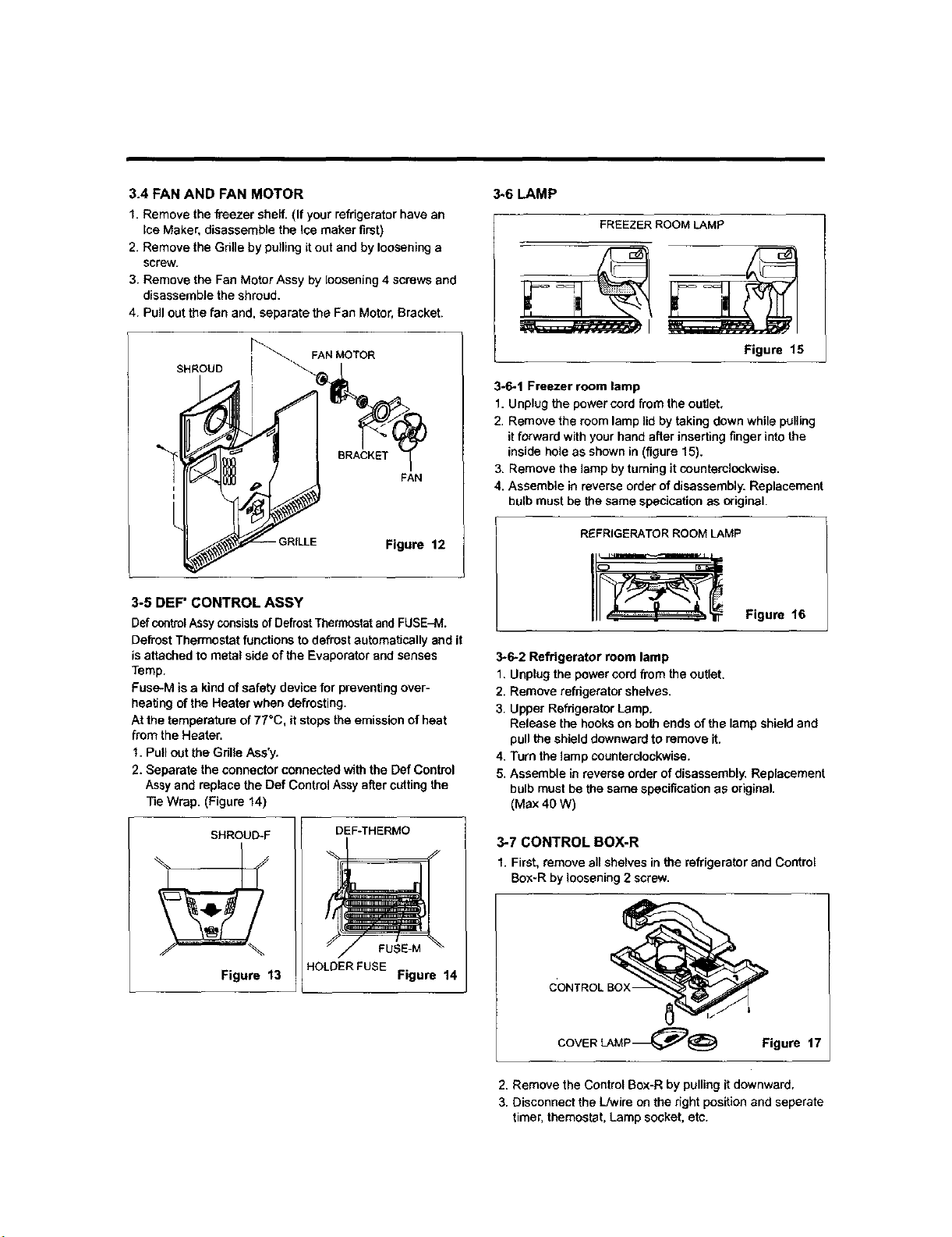
3.4 FAN AND FAN MOTOR
1. Remove the freezer shelf. (If your refrigerator have an
Ice Maker, disassemble the ice maker first)
2. Remove the Gritle by pulling it out and by loosening a
screw.
3. Remove the Fan Motor Assy by loosening 4 screws and
disassemble the shroud.
4. Pull out the fan and, separate the Fan Motor, Bracket.
SHROUD
FAN
-GRILLE Figure 12
3-5 DEF" CONTROL ASSY
Def controlAssy consistsof DefrostThermostatand FUSE-M.
Defrost Thermostat functions to defrost automatically and it
is attached to metal side of the Evaporator and senses
Temp.
Fuse-M is a kind of safety device for preventing over-
beating of the Heater when defrosting.
At the temperature of 77°C, it stops the emission of heat
from the Heater.
1. Pull out the Gdlle Ase'y.
2. Separate the connector connected with the Def Control
Assy and replace the Def Control Assy after cutting the
Tie Wrap. (Figure 14)
SHROUD-F
Figure 13
DEF-THERMO
FUSE-M
HOLDERFUSE
Figure 14
3_6 LAMP
FREEZER ROOM LAMP
Figure 15
3-6-1 Freezer room lamp
1. Unplug the power cord from the outlet,
2. Remove the room lamp lid by taking down while pulling
it forward with your hand after inserting finger into the
inside bole as shown in (figure 15).
3. Remove the lamp by taming it counterclockwise.
4, Assemble in reverse order of disassembly. Replacement
bulb must be the same specication a_ original.
REFRIGERATOR ROOM LAMP
Figure 16
3-6-2 Refrigerator room lamp
1. Unplug the power cord from the outlet,
2. Remove refrigerator shelves.
3. Upper Refrigerator Lamp.
Release the hooks on both ends of the lamp shield and
pull the shield downward to remove it.
4. Turn the lamp counterclockwise.
5. Assemble in reverse order of disassembly, Replacement
bulb must be the same specification as original.
(Max 40 W)
3-7 CONTROL BOX-R
1. First, remove all shelves in the refrigerator and Control
Box-R by loosening 2 screw.
CONTROL BOX-
COVER LAMP_)@ Figure 17
2. Remove the Control Box-R by pulling it downward,
3. Disconnect the L/wire on the right position and seperate
timer, themostet, Lamp socket, etc.
Loading ...
Loading ...
Loading ...