SERVICING PRECAUTIONS
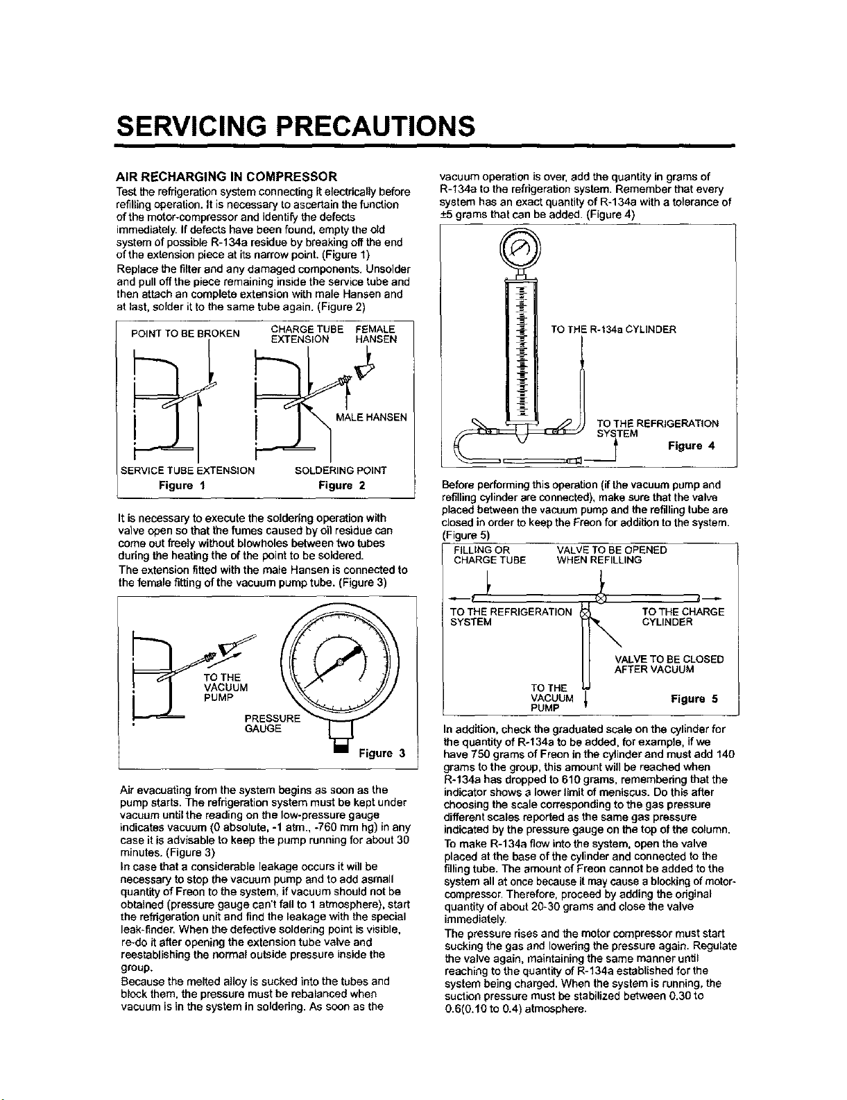
AIR RECHARGING IN COMPRESSOR
Test the refrigeration system connecting it electrically before
refilling operation. It is necessary to ascertain the function
of the moter-comprassor and identify the defects
immediately. If defects have been found, empty the old
system of possible R-134a residue by breaking off the end
of the extension piece at its narrow point. (Figure 1)
Replace the filter and any damaged components. Uneelder
and pulloff the piece remaining inside the service tube and
then attach an complete extension with male Hansen and
at last, solder itto the same tube again. (Figure 2)
POINT TO BE BROKEN
SERVICE TUBE EXTENSION
Figure f
CHARGE TUBE FEMALE
EXTENSION HANSEN
"_ MALE HANSEN
SOLDERING POINT
Figure 2
It is necessary to execute the soldering operation with
valve open so that the fumes caused by oil residue can
come out freely without blowholes between two tubes
during the heating the of the point to be soldered.
The extension fitted with the male Hansen is connected to
the female fitting of the vacuum pump tube. (Figure 3)
__RESS!E
GAUGE
Air evacuating from the system begins as soon as the
pump starts. The refrigeration system must be kept under
vacuum untilthe reading on the low-pressure gauge
indicates vacuum (0 absolute, -1 atm., -760 mm hg) in any
case it is advisable to keep the pump running for about 30
minutes. (Figure 3)
In case that a considerable leakage occurs it will be
necessary to stop the vacuum pump and to add asmall
quantity of Freon to the system, if vacuum should not be
obtained (pressure gauge can't fall to 1 atmosphere), start
the refrigeration unit and find the leakage with the special
leak-finder, When the defective soldering point is visible,
re-do it after opening the extension tube valve and
reestablishing the normal outside pressure inside the
group.
Because the melted alloy is sucked into the tubes and
block them, the pressure must be rebalanced when
vacuum is in the system in soldering. As soon as the
vacuum operation is over, add the quantity in grams of
R-134a to the refrigeration system. Remember that every
system has an exact quantity of R-134a with a tolerance of
-+5grams that can be added. (Figure 4)
TO THE R-t34a CYLINDER
L
_ _ TOTHE REFRIGERATION
SYtTEM Figure 4
Before performing this operation (if the vacuum pump and
refilling cylinder are connected), make sure that the valve
placed between the vacuum pump and the refilling tube are
closed in order to keep the Freon for addition to the system.
(Figure 5)
FILLING OR VALVE TO BE OPENED
CHARGE TUBE WHEN REFILLING
TO THE REFRIGERATION TO THE CHARGE
SYSTEM CYLINDER
VALVE TO BE CLOSED
AFTER VACUUM
TOTHE
VACUUM _ Figure 5
PUMP
I
In addition, check the graduated scale on the cylinder for
the quantity of Ro134a to be added, for example, if we
have 750 grams of Fraon in the cylinder and must add 140
grams to the group, this amount will be reached when
R-134a has dropped to 610 grams, remembedng that the
indicator shows a lower limit of meniscus. Do this after
choosing the scale corresponding to the gas pressure
different scales reported as the same gas pressure
indicated by the pressure gauge on the top of the column.
To make R-134a flow into the system, open the valve
placed at the base of the cylinder and connected to the
fillingtube. The amount of Freon cannot be added to the
system all at once because it may cause a blocking of motor°
compressor. Therefore, proceed by adding the original
quantity of about 20-30 grams and close the valve
immediately.
The pressure rises and the motor compressor must start
sucking the gas and lowering the pressure again. Regulate
the valve again, maintaining the same manner until
reaching to the quantity of R-134a established for the
system being charged. When the system is running, the
suction pressure must be stabilized b_ween 0.30 to
0.6(0.10 to 0.4) atmosphere.
1. SPECIFICATIONS
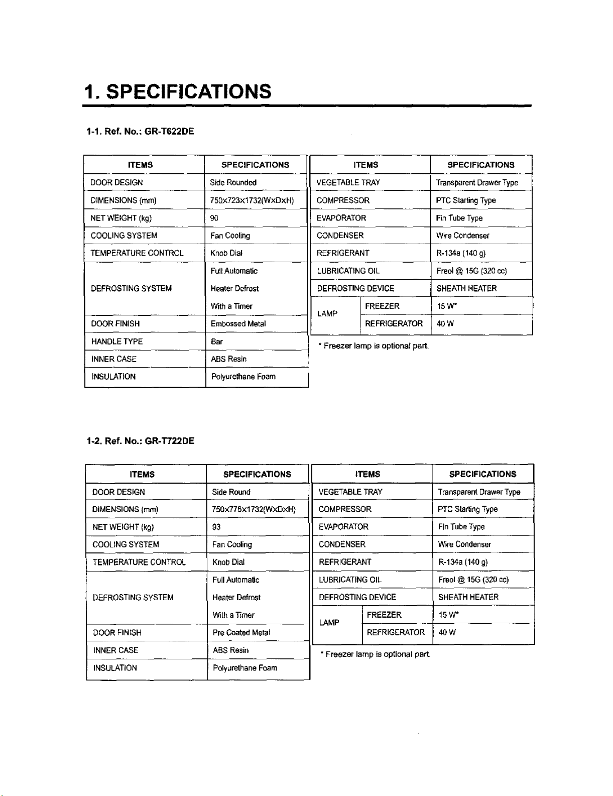
1-1. Ref. No.: GR-T622DE
ITEMS
DOOR DESIGN
DIMENSIONS (ram)
NET WEIGHT (kg)
COOLING SYSTEM
TEMPERATURE CONTROL
DEFROSTING SYSTEM
DOOR FINISH
HANDLE TYPE
INNER CASE
INSULATION
SPECIFICATIONS
Side Rounded
750×723×1732(WxDxH)
9O
Fan Cooling
KnobDial
FullAutomatic
Heater Defrost
Witha "i3mer
EmbossedMetal
Bar
ABS Resin
Polyurethane Foam
ITEMS
VEGETABLE TRAY
COMPRESSOR
EVAPORATOR
CONDENSER
REFRIGERANT
LUBRICATING OIL
DEFROSTING DEVICE
FREEZER
LAMP
REFRIGERATOR
* Freezer lamp is optional part,
SPECIFICATIONS
TransparentDrawer Type
PTC Starting Type
Fin Tube Type
Wire Condenser
R-134a (140 g)
Freol@ 15G (320 cc)
SHEATH HEATER
15W*
4OW
1-2. Ref. No.: GR-T722DE
ITEMS
DOOR DESIGN
DIMENSIONS (ram)
NET WEIGHT (kg)
COOLING SYSTEM
TEMPERATURE CONTROL
DEFROSTING SYSTEM
DOOR FINISH
INNER CASE
INSULATION
SPECIFICATIONS
Side Round
750x776x1732(WxDxH)
93
Fan COoling
Knob Dial
Full Automatic
Heater Defrost
With a Timer
Pre Coated Metal
ABS Resin
Polyurethane Foam
ITEMS
VEGETABLE TRAY
COMPRESSOR
EVAPORATOR
CONDENSER
REFRIGERANT
LUBRICATING OIL
DEFROSTING DEVICE
FREEZER
LAMP
REFRIGERATOR
* Freezer lamp is optional part.
SPECIFICATIONS
Transparent DrawerType
PTC Starting Type
FinTube Type
Wire Condenser
R-134a (140 g)
Freol@ 1,5G(320 co)
SHEATH HEATER
15 W*
40 W
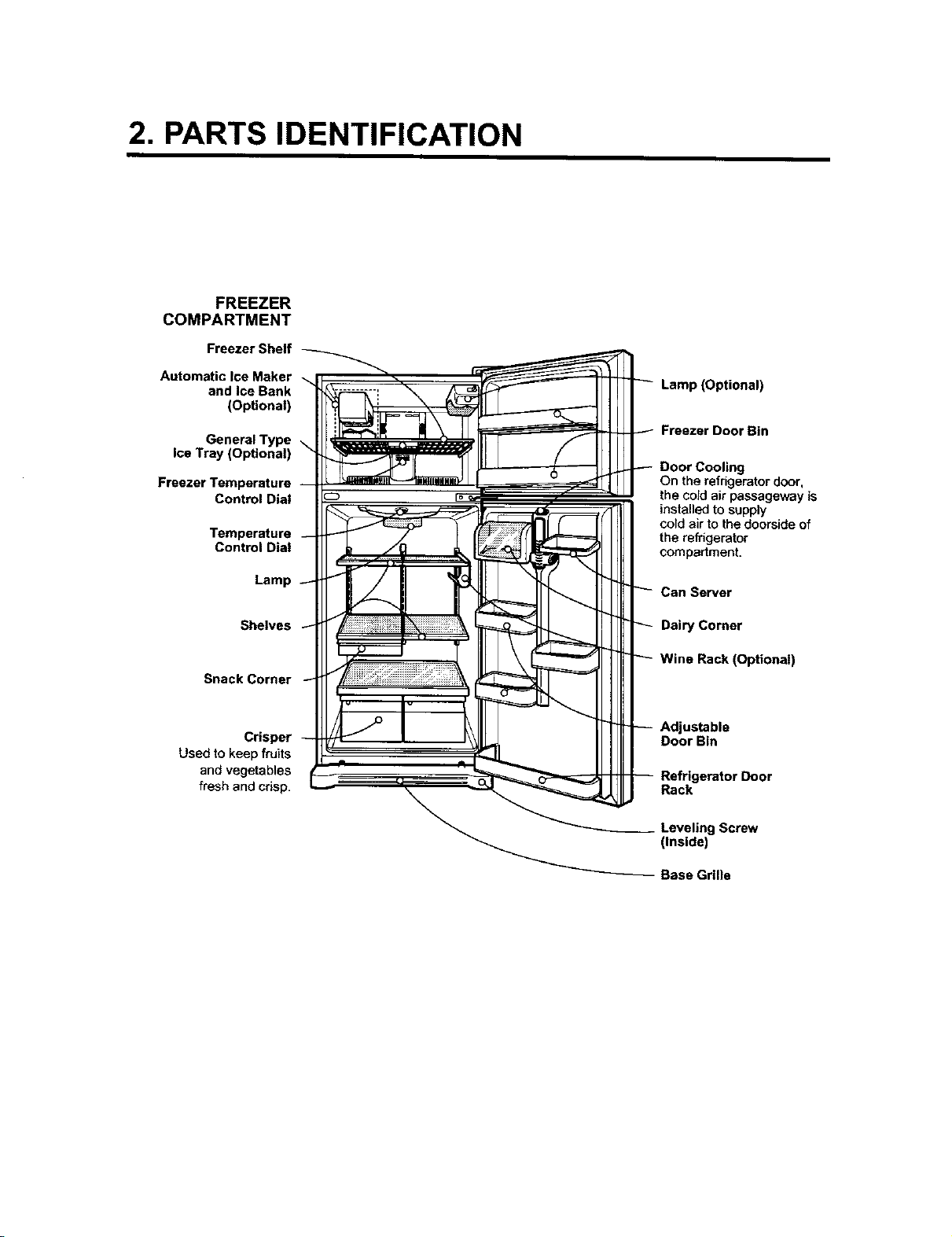
2. PARTS IDENTIFICATION
FREEZER
COMPARTMENT
Freezer Shelf
Automatic Ice Maker
and Ice Bank
(Optional)
General Type
Ice Tray (Optional)
Freezer Temperature
Control Dial
Temperature
Control Dial
Lamp
Shelves
Snack Corner
Lamp (Optional)
Freezer Door Bin
Door Cooling
On the refrigeratordoor,
the cold air passageway is
installedto supply
coldair to the doorsideof
the refrigerator
compartment.
Can Server
Dairy Corner
Wine Rack (Optional)
Crisper
Used to keep fruits
and vegetables
fresh and crisp.
Adjustable
Door Bin
Rack
Screw
(Inside)
Base Grllle
3. DISASSEMBLY
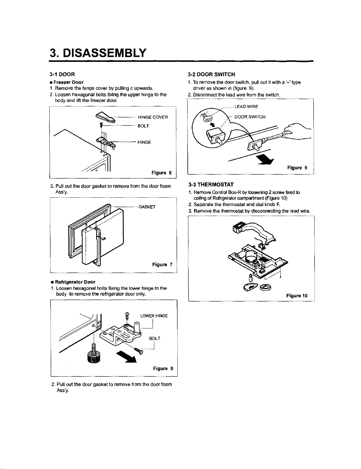
3-1 DOOR
• Freezer Door
1. Remove the hinge cover by pulling it upwards.
2. Loosen hexagonal boils fixing the upper hinge to the
body and lift the freezer door.
{_ HINGE COVER
BOLT
HINGE
Figure 6
3. Pull out the door gasket to remove from the door foam
Ass'y.
GASKET
Figure 7
• Refrigerator Door
1. Loosen hexagonal botts fixing the lower hinge to the
body to remove the refrigerator door only.
LOWERHINGE
3-2 DOOR SWITCH
1. To remove the door switch, pull out it with a '-' type
driver as shown in (figure 9).
2. Disconnect the lead wire from the switch.
LEAD Wl RE
Figure 9
3-3 THERMOSTAT
1. Remove Control Box-R by loosening 2 screw fixed to
ceiling of Refdg_ator compadrnent (Figure 10)
2. Separate the thermostat and dial knob F_
3. Remove the thermostat by disconnecting the lead wire.
Figure 10
BOLT
Figure 8
2. Pullout the door gasket to removefrom the door foam
Ass'y.
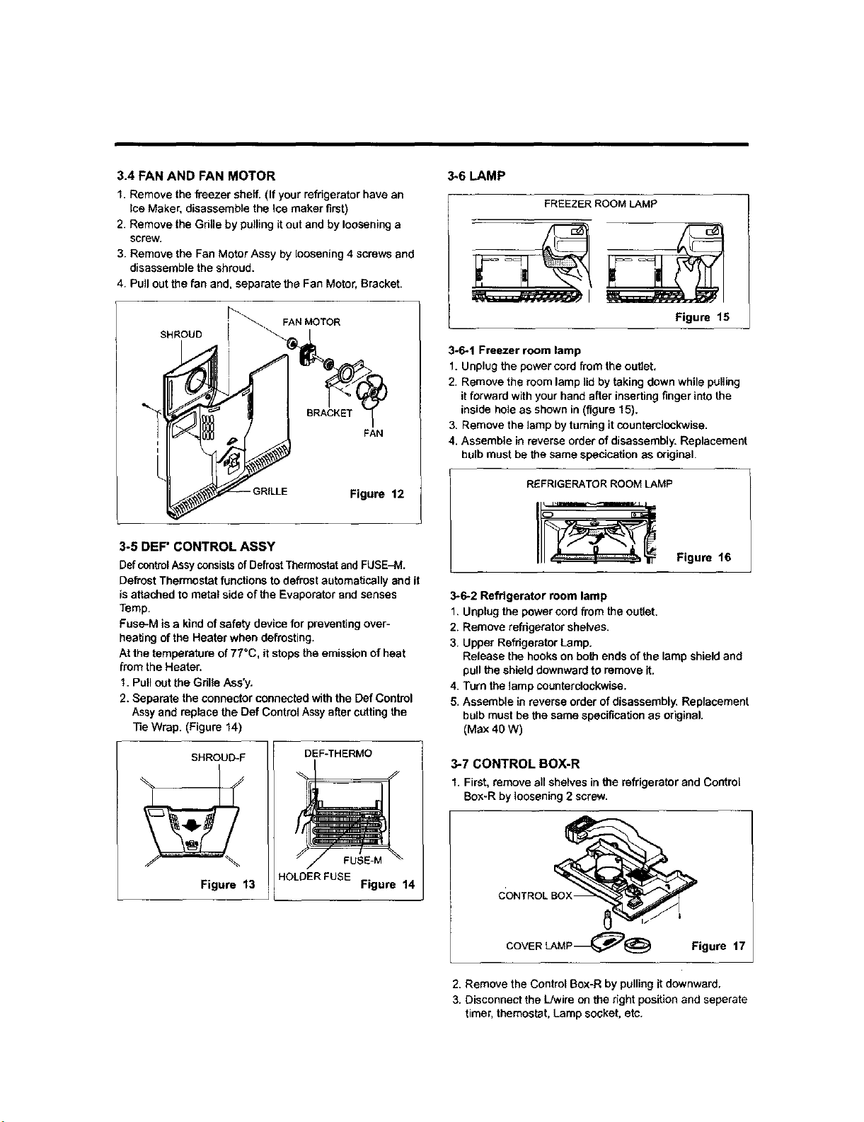
3.4 FAN AND FAN MOTOR
1. Remove the freezer shelf. (If your refrigerator have an
Ice Maker, disassemble the ice maker first)
2. Remove the Gritle by pulling it out and by loosening a
screw.
3. Remove the Fan Motor Assy by loosening 4 screws and
disassemble the shroud.
4. Pull out the fan and, separate the Fan Motor, Bracket.
SHROUD
FAN
-GRILLE Figure 12
3-5 DEF" CONTROL ASSY
Def controlAssy consistsof DefrostThermostatand FUSE-M.
Defrost Thermostat functions to defrost automatically and it
is attached to metal side of the Evaporator and senses
Temp.
Fuse-M is a kind of safety device for preventing over-
beating of the Heater when defrosting.
At the temperature of 77°C, it stops the emission of heat
from the Heater.
1. Pull out the Gdlle Ase'y.
2. Separate the connector connected with the Def Control
Assy and replace the Def Control Assy after cutting the
Tie Wrap. (Figure 14)
SHROUD-F
Figure 13
DEF-THERMO
FUSE-M
HOLDERFUSE
Figure 14
3_6 LAMP
FREEZER ROOM LAMP
Figure 15
3-6-1 Freezer room lamp
1. Unplug the power cord from the outlet,
2. Remove the room lamp lid by taking down while pulling
it forward with your hand after inserting finger into the
inside bole as shown in (figure 15).
3. Remove the lamp by taming it counterclockwise.
4, Assemble in reverse order of disassembly. Replacement
bulb must be the same specication a_ original.
REFRIGERATOR ROOM LAMP
Figure 16
3-6-2 Refrigerator room lamp
1. Unplug the power cord from the outlet,
2. Remove refrigerator shelves.
3. Upper Refrigerator Lamp.
Release the hooks on both ends of the lamp shield and
pull the shield downward to remove it.
4. Turn the lamp counterclockwise.
5. Assemble in reverse order of disassembly, Replacement
bulb must be the same specification as original.
(Max 40 W)
3-7 CONTROL BOX-R
1. First, remove all shelves in the refrigerator and Control
Box-R by loosening 2 screw.
CONTROL BOX-
COVER LAMP_)@ Figure 17
2. Remove the Control Box-R by pulling it downward,
3. Disconnect the L/wire on the right position and seperate
timer, themostet, Lamp socket, etc.
4. ADJUSTMENT
_ICOMPRESSOR
4-1-I Role
The compressor intakes low temperature and low pressure
gas evaporated from Evaporator of the Refrigerator, and
condenses thisgas to high temperature and high pressure
gas, and then plays delivehng role to Condenser.
4-1-2 Composition
The Compressor is Composed of Compressor Apparatus
compressing gas, Compressor Motor moving Compressor
Apparatus and Case protecting Compressor Apparatus
and Motor. There are PTC-Starter, and Over Load
protector (OLP) in the Compressor outside. On the other
hand, because the Compressor consistsof 1/100gram pmcassing
precisioncomponentsand is sealedafter production in absence
of dustor humidity, deal and repair withcare.
4-1-3 Note for Usage
(1) Be careful not to allow over-voflage and over-current.
(2) No Strike
If applying forcible power or strike (dropping or careless
deaitng), poor operation and noise may occur.
(3) Use proper eiecbic components appropriate to the
Compressor.
(4) Note to Keep Compressor.
If Compressor gets wet in the rain and rust in the pin of
Hermetic Terminal, the result may be poor operation
and poor contact may cause.
(5) Be careful that dust, humidity, and flux welding don't
inflow in the Compressor inside in replacing the
Compressor. Dust, humidity, and flux due to welding
which inflows to Cylinder may cause Iockage and noise.
4-2 PTC-STARTER
4-2-1 Composition of PTC-Starter
(1) PTC (Positive Temperature Coefficient) is a no-contact
semiconductor starting device which uses ceramic
material and this matedal consists of BaTiO3.
(2) The higher the temperature is, the higher becomes the
resistance value. These features are used as starting
device for the Motor.
4.2-2 Role of PTC-Starter
(1) PTC is attached to Hermetic Compressor used for
Refrigerator, Show Case and starts Motor.
(2) Compressor for household refrigerator applies to
single-phase induction Motor.
For normal operation of the single-phase induction
motor, in the starting operation flows in both main coil
and sub-coil. After the starting isover, the current in
subceit is cut off. The proper features of PTC play all
the above roles. So, PTC is used as a motor starting
device.
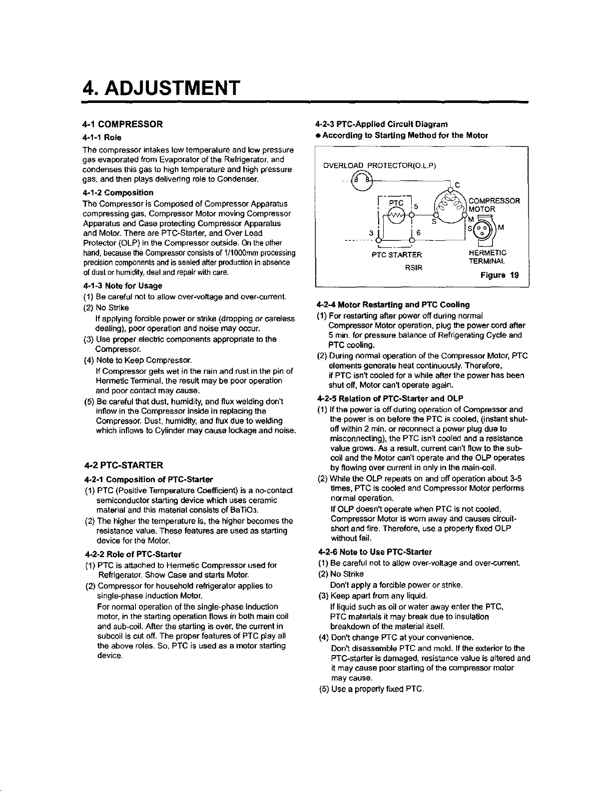
4,.2-3 PTC-Applied Circuit Diagram
• According to Starting Method for the Motor
OVERLOAD PROTECTOR(O.L.P)
_ [--_-C7 = _'_ COMPRESSOR
' '"* MOTOR
PTC STARTER HERMETIC
TERMINAL
RSIR
Figure 19
4-2-4 Motor Restarting and PTC Cooling
(1) For restarting after power off dudng normal
Compressor Motor operation, plug the power cord after
5 rain. for pressure balance of Refngerating Cycle and
PTC cooling.
(2) During normal operation of the Compressor Motor, PTC
elements generate heat continuously. Therefore,
if PTC isn't cooled for a while after the power has been
shut off, Motor can't operate again.
4-2-5 Relation of PTC-Starter and OLP
(1) If the power is offduring operation of Compressor and
the power is on before the PTC is cooled, (instant shut-
off within 2 rata, or reconnect a power plug due to
misconneotthg), the PTC isn't cooled and a resistance
value grows. As a result, current can't flow to the sub-
coil and the Motor can't operate and the OLP operates
by flowing over current in only in the main-coil,
(2) While the OLP repeats on and off operation about 3-5
times, PTC is cooled and Compressor Motor performs
normal operation.
If OLP doesn't operate when PTC is not cooled,
Compressor Motor is worn away and causes circuit-
short and fire. Therefore, use a properly fixed OLP
without fail.
4-2-6 Note to Use PTC.Starter
(1) Be careful not to allow over-voltage and over-current.
(2) No Strike
Don't apply a forcible power or strike.
(3) Keep apart from any liquid.
If liquid such as oil or water away enter the PTC,
PTC matedals it may break due to insulation
breakdown of the material itself.
(4) Don't change PTC at your convenience.
Don't disassemble PTC and mold. If the exterior to the
PTC-starter is damaged, resistance value is altered and
it may cause poor starting of the compressor motor
may cause,
(5) Use a prepedy flied PTC.
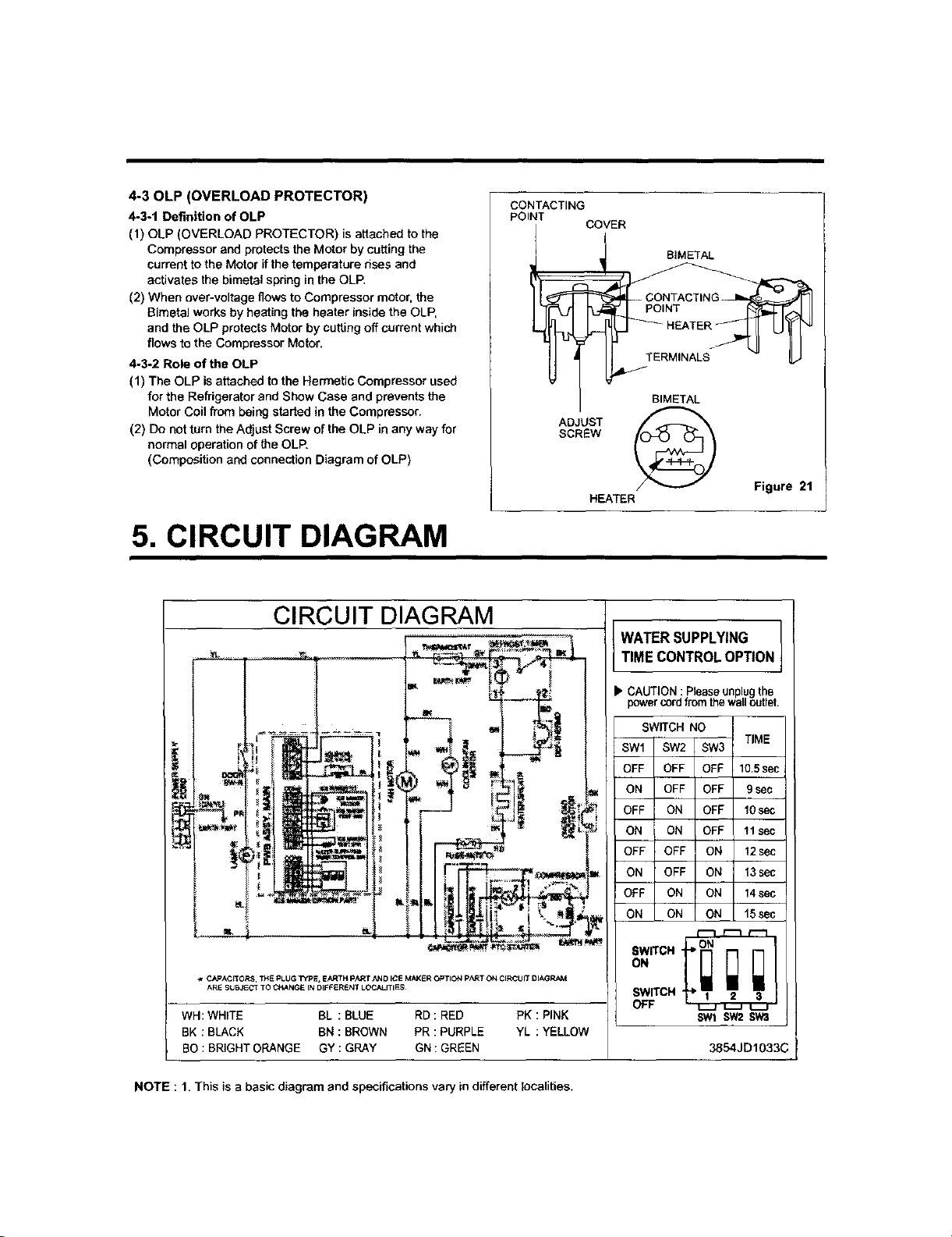
4-30LP(OVERLOAD PROTECTOR)
4-3-1 Definition of OLP
(1) OLP (OVERLOAD PROTECTOR) is attached to the
Compressor and protects the Motor by cutting the
current to the Motor ifthe temperature rises and
activates the bimetal spring in the OLP.
(2) When over-voltage flows to Compressor motor, the
Bimetal works by heating the heater inside the OLP,
and the OLP protects Motor by cutting off current which
flows to the Compressor Motor.
4-3-2 Role of the OLP
(1) The OLP is attached to the Hermetic Compressor used
for the Refrigerator and Show Case and prevents the
Motor Coil from being started in the Compressor.
(2) Do not turn the Adjust Screw of the OLP in any way for
normal operation of the OLP.
(Composition and connection Diagram of OLP)
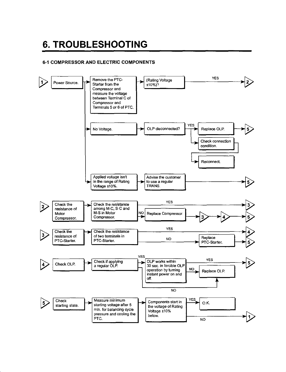
5. CIRCUIT DIAGRAM
CONTACTING
POINT
COVER
BIMETAL
CONTACTING
POINT
HEATER
BIMETAL
ADJUST
SCREW
Figure 21
HEATER
CIRCUIT DIAGRAM ]
=-,
WATERSUPPLYING
TIMECONTROLOPTION
b"CAUTION : Pleaseunplugthe
power cordfromthe wailoutlet.
SWITCH NO
TIME
SW1 SW2 SW3
OFF OFF OFF 10,5sec
ON OFF OFF 9sec
W CAPACITORS, T_E PLUG TYPE, EARTH p_,R ]t _ND ICE MAKE R OPTION pART ON CIRCU _T DIAG
ARE StJBJE_T TO C_,ANGE IN DIFFeReNT LOC,t_.ITIES
WH: WHITE BL : BLUE RD : RED PK : PINK
BK : BLACK BN : BROWN PR : PURPLE YL : YELLOW
BO : BRIGHT ORANGE GY : GRAY GN :GREEN
OFF ON OFF 10sec
ON ON OFF 11sec
OFF OFF ON 12sec
ON OFF ON 13sec
OFF ON ON 14sec
ON ON ON 15 sec
swITCH ' "_ ON
SWITCH _ 2 3
OFF _
SWt SW2SW'3
3854JD1033,
NOTE : 1. This is a basic diagram and specifications vary in different localities.
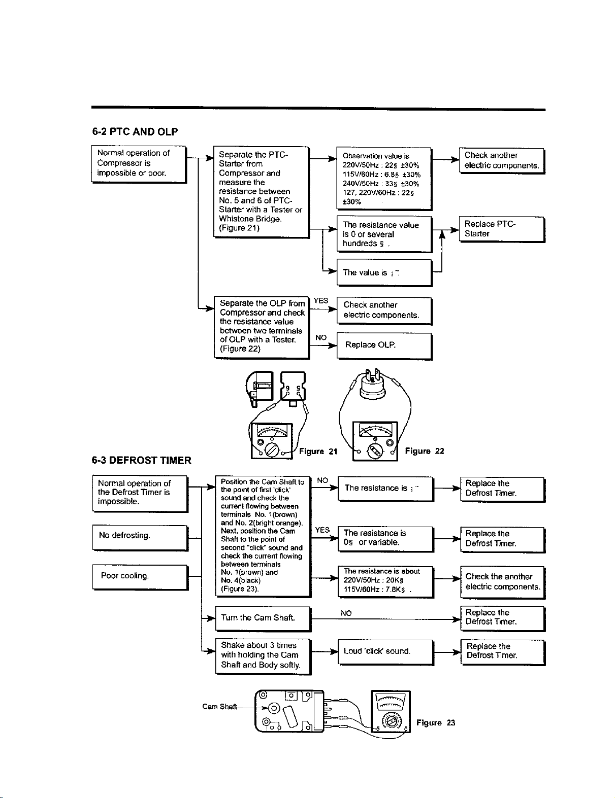
6. TROUBLESHOOTING
6-1 COMPRESSOR AND ELECTRIC COMPONENTS
[_ Power Source.
Remove the PTC-
Starter from the
Compressor and
measure the voltage
between Terminal C of
Compressor and
Terminals 5 or 6 of PTC.
_ (Rating Voltage
±10%)? I YES _,[_
No Voltage. _ OLP disconnected?
Applied voltage isnl
-_. in the range of Rating
Voltage ±10%.
_._ dvise the customer
to use a regular
TRANS.
Replace OLP.
_,,_ Check connection
| condition, _-_
ReconnectI
Check the
resistance of
Motor
Compressor.
_ heck the resistance N_O
among M-C, S-C and
M-S in Motor
Compressor.
ChocktheresistanceI
of two terminals in
PTC-Starter.
YES v_"=_
Replace Compressor.
[_ Check the YES
resistance of [ Replace
PTC-Starter. NO ]D/ PTC-Starter.
YES
[_ Check OLP. _-_ Check if applying _ OLP works within il YES _I I a regular OLP. L 130 sec. in forcible OLPI t
I I I_ Ioperationbytuming _ ReplaceOLP.
I
NO
starting state. I r I starting voltage after 5 I I the voltage of Rating " '
I I rain. for balancing cycle I I Voltage ±10%
| pressure and cooling the I I below. ]l, _'_
/ PTc" I I / "°
LY
6-2 PTC AND OLP
Normal operation of I--
Compressor is
/
impossible or poor.
6-3 DEFROST TIMER
Separate the PTC-
Starter from
Compressor and
measure the
resistance between
No. 5 and 6 of PTC-
Starter with a Tester or
Whistone Bddge.
(Figure 21)
Separate the OLP from [YESJ
">' Compressor and check
the resistance value I I
between two terminals I
of OLP with a Tester,
(Figure 22)
F_Figure21
Observation valueis I _1
220V/50Hz : 225 ±30%
115V/60Hz : 6.8§ ±30%
240V!50Hz : 33_ ±30%
127, 220V/6OHz :225
±30%
The resistance value J _1
is 0 or several
hundreds § .
The value is i "i
Check another j
elec_c components.
I
Replace OLP.
22
Check another ielectdccomponents.
Replace PTC-
Starter
I
Normal operation of
the Defrost Timer is
impossible.
I No defrosting.
I Poor cooling.
Position the Cam Shaft to
the point of first *click'
sound and check the
current flowing between
terminals No. 1(brown)
and No. 2(bright orange).
Next, position the Cam
Shaft to the point of
second "click" sound and
check the current flowing
between terminals
No. 1(brown) and
NO. 4(black)
(Figure 23).
Turn the Cam Shaft.
I Sheke about 3 times
with holding the Cam
Shaft and Body softly.
-_The resistance is _- t_
._The resistance is _{
0_ or variable.
_]_ The resistanceis about _f
220V/5OHz :20Ks
t15V/6OHz : 7.8K5 .
I ,!
I_ Loud 'click' sound. I_
Replace the I
Defrost Timer.
Replace the I
Defrost Timer.
Checkthe another i
ii
electric components. I
Replace the I
Defrost Timer.
Replace the I
Defrost Timer,
p
r_ Figure 23
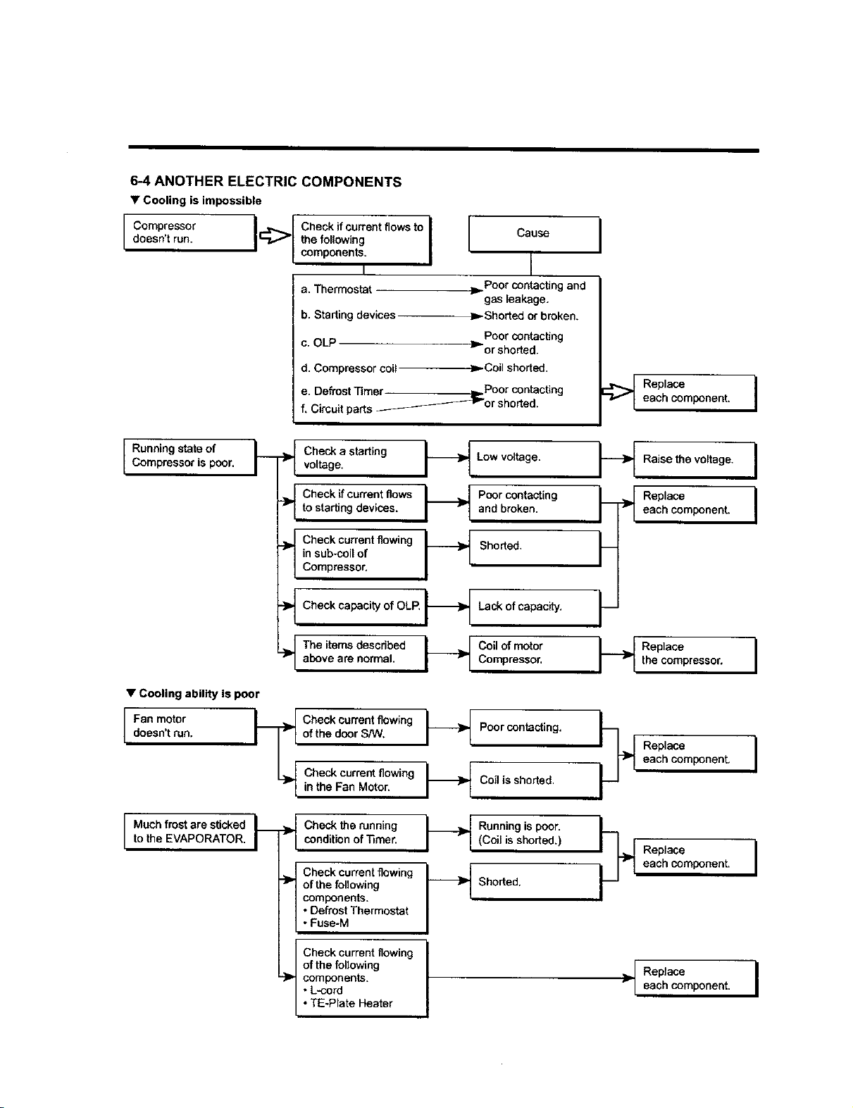
6-4 ANOTHER ELECTRIC COMPONENTS
• Cooling is impossible
doesn't run. _ the following I
components. I
I
a. Thermostat
b. Starting devices
Cause
I
Poor contacting and
gas leakage.
Shorted or broken.
Poor contacting
c. OLP 1_ or shorted.
d. Compressor COil
._- Coil shorted.
e. DefrostTimer _ Poor contacting
f, Circuit parts ____-_-_'or shorted.
i
Replace I
each component.
Running state of F
Compressor is poor. ">
• Cooling ability is poor
I Fan motor
doesn't run.
I Muchfrost are sticked
to the EVAPORATOR.
-}P
voltage.Checka starting _ Low voltage.
i I
Check if current flows _ Poor contacting
to starting devises. _ and broken.
Compressor,inCheckcurrentflowingsub.coilof _ Shorted.
Check capacity of OLP. I_
"_ Lack of capacity.
._The items described I_ Coil of motor
above are normal. Compressor.
ofCheckcurrentflowingthedoor S/W. I_ Poor contacting.
Check current flowing I_in the Fan Motor. Coil is shorted.
Check the running _ Running is poor.
condition of ]_mer. I rl (Coil is shorted,)
Check current flowing _ _1
of the following _ Shorted.
components.
• Defrost Thermostat
• Fuse-M
Check current flowing I
of the following
I
components.
• L-cord
• TE-Plate Heater
,I
Raise the voltage.
Replace
each component.
Replace
the compressor,
I
I
I
Replace I
each component,
Replace Ieach component.
Replace I
each component.
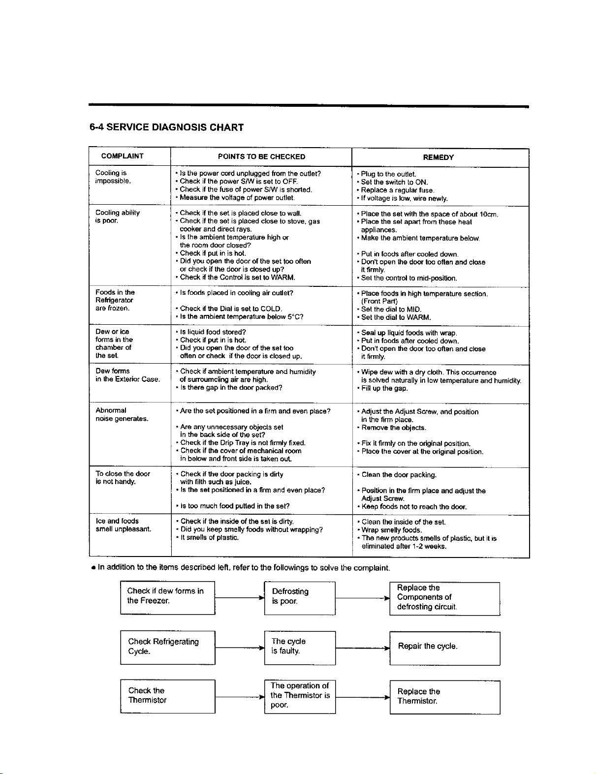
6-4 SERVICE DIAGNOSIS CHART
COMPLAINT POINTS TO BE CHECKED REMEDY
Cooling is • Is the power cord unplugged from the outlet? - Plug to the ouUet.
impossible. • Check if the power S/W is set to OFF. * Set the switch to ON.
• Check if the fuse of power S/W is shorted. • Replace a regular fuse,
• Measure the voltage of power outlet. • If voltage is low, wire newly.
Cooling ability
is poor.
• Check if the set is placed close to wall.
• Check if the set is placed ctose to stove, gas
cooker and direct rays.
• Is the ambient temperature high or
the room door closed?
• Check ff put in is hot,
• Did you open the door of the set too often
or check if the door is closed up?
• Check ff the Control is set to WARM.
• Place the set with the space of about 1Ocm.
• Place the set apart from these heat
appliances.
• Make the ambient temperature below.
• Put in foods after cooled down.
• DOn_Lopen the door too often and close
it firmly.
• Set the control to mid-pesition.
Foods in the * Is foods placed in cooling air outlet?, • Place foods in high temperature section,
Refrigerator (Front Part)
are frozen. • Chock if the Dial is set to COLD. - Set the dial to MID.
• Is the ambient temperature below 5=C? • Set the dial to WARM.
Dew or ice • Is liquid food stored? - Seal up liquid foods with wrap.
forms in the • Check if put in is hot. • Put in foods alter cooled down.
chamber of • Did you open the door of the set too • Don't open the door too often and close
the set. often or check if the door is closed up. it firmly.
Dew forms , Check if ambient temperature and humidity • Wipe dew with a dry cloth. This occurrence
in the Exterior Case. of surroumc[ing air are high. is solved naturally in low temperature and humidity.
• Is there gap in the door packed? • Fill up the gap.
Abnormal • Are the set positioned in a firm and even place? • Adjust the Adjust Screw, and position
noise generates, in the firm place.
• Are any unnecessary objects set - Remove the objects.
in the back side of the set?
• Check if the Ddp Tray is not firmly fixed. • Fix it firmly on the original position.
• Check if the cover of mechanical room • Place the cover at the odginal position,
in below and front side is taken out,
To close the door • Check if the door packing isdirty - Clean the door packing,
is not handy, with filth such as juice.
• Is the set positioned in a firm and even place? • Position in the firm place and adjust the
Adjust Screw.
• Is too much food putted in the set? • Keep foods not to reach the door.
Ice and foods • Check if the inside of the set is dirty. • Clean the inside of the set.
smell unpleasant. . Did you keep smelly foods without wrapping? • Wrap smelly foods.
• It smells of plastic. - The new products smells of plastic, but it is
eliminated after 1-2 weeks.
• In addition to the items described left. refer to the followings to solve the complaint,
I
Checkif dew forms in I
L
the Freezer.
Defrosting
is poor.
Replace the
Components of
defrosting circuit
Check Refrigerating
Cycle.
Check the
Thermistor
The cycle
is faulty,
The operation of
the Thermistor is
poor.
Repair the cycle.
Replace the
Thermistor.
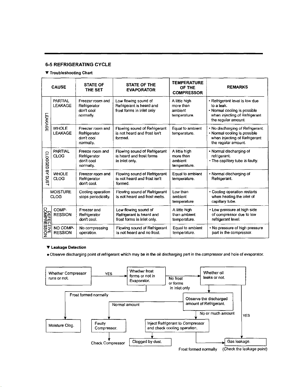
6-5 REFRIGERATING CYCLE
• Troubleshooting Chart
STATE OF STATE OF THE TEMPERATURE
CAUSE OF THE REMARKS
THE SET EVAPORATOR
COMPRESSOR
PARTIAL Freezer room and Low flowing sound of A little high • Refrigerant level is low due
LEAKAGE Refrigerator Refrigerant is heard and more than to a leak.
don't cool frost forms in inlet only ambient • Normal cooling is possible
r-
normally, temperature, when injecting of Refrigerant
the regular amount.
mO WHOLE Freezer room and Flowing sound of Refrigerant Equal to ambient • No discharging of Refrigerant.
LEAKAGE Refrigerator is not heard and frost isn't temperature. * Normal cooling is possible
don't cool formed, when injecting of Refrigerant
normally, the regular amount.
PARTIAL Freeze room and Flowing sound of Refrigerant A little high ° Normal discharging of
CLOG Refrigerator is heard and frost forms more than refrigerant.
don't cool in inlet only. ambient * The capillary tube isfaulty.
rn normally, temperature.
E_
_o
-< WHOLE Freezer room and Flowing sound of Refrigerant Equal to ambient • Normal discharging of
C° CLOG Refrigerator is not heard and frost isn't temperature. Refrigerant.
u> don't cool. formed.
MOISTURE Cooling operation Flowing sound of Refrigerant Low than • Cooling operation restarts
CLOG stops periodically, is not heard and frost melts, ambient when heating the inlet of
I temperature capillary tube.
o COMP- Freezer and Low flowing sound of A little high ° Low pressure at high side
O _ RESSION Refrigerator Refrigerant is heard and than ambient of compressor due to low
"om
:o m don't cool. frost forms in inlet only. temperature, refngerant level.
m¢3
_ NO COMP- No compressing Flowing sound of Refrigerant Equal to ambient • No pressure of high pressure
O m RESSION operation, is not heard and no frost, temperature, part in the compressor.
z
• Leakage Detection
• Observe discharging point of refrigerant which may be in the oil discharging part in the compressor and hole of evaporator.
Whether Compressor YES
runs or not.
Frost formed normalli
I Moistura Clog. ] FaultyCompressor.
I Whether frost
> forms or not in
Evaporator.
J
Normal amoont
Check Compressor [ Clogged by dust.
I Whether oil
No frost > leaks or not.
or forms
in inlet only _,
Observe the discharged
amount of Refrigerant.
No or much amount
Inject Refrigerant to Compressor
and check coo ng operat on.
j
Frost formed normally
YES
>1 Gas leakage. I
(Check the leakage point)
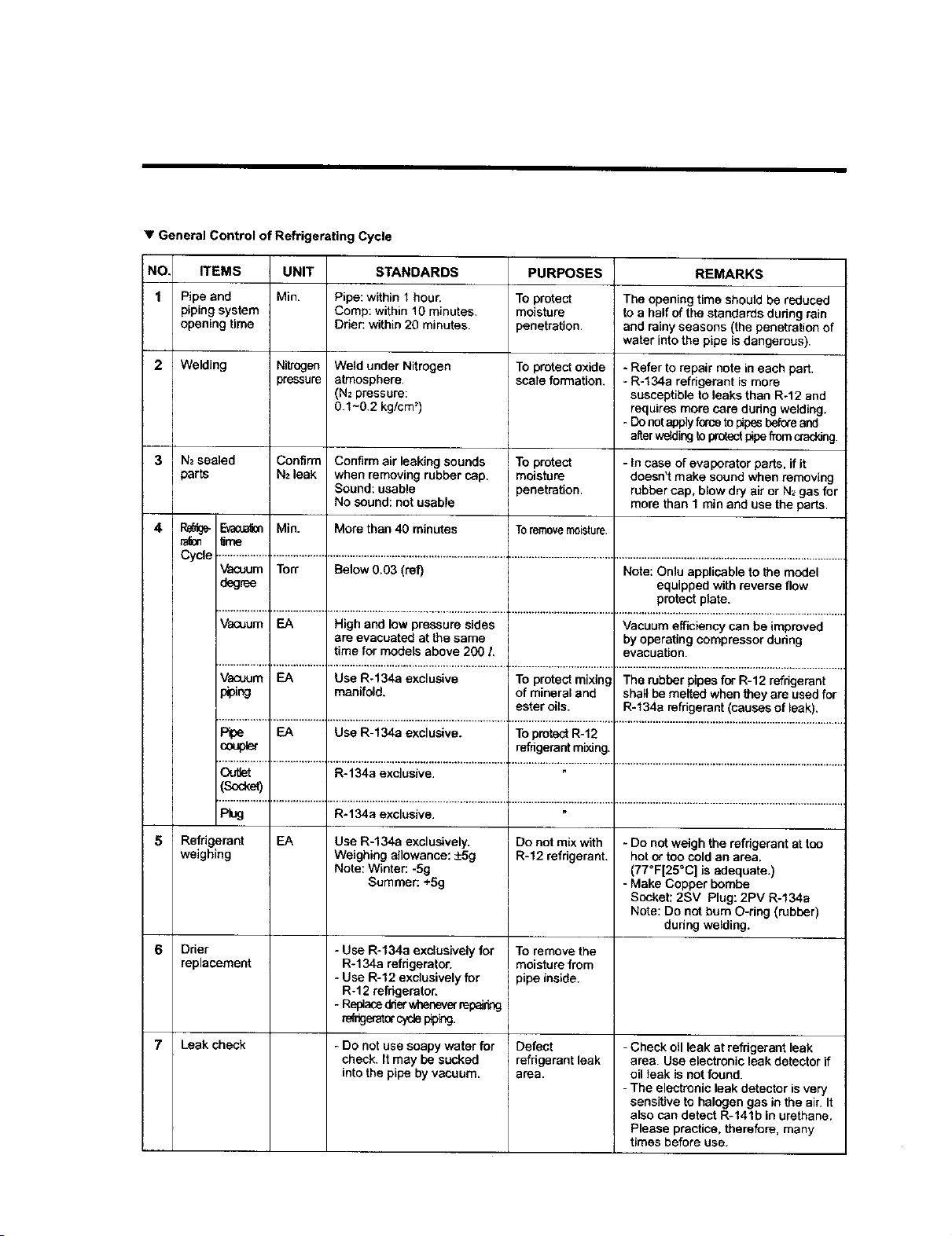
• General Control of Refrigerating Cycle
NO, ITEMS UNIT STANDARDS
1 Pipe and Min. Pipe: within 1 hour.
piping system Comp: within 10 minutes.
opening time Drier: within 20 minutes.
Welding Nitrogen Weld under Nitrogen
pressure atmosphere.
(N2 pressure:
0.1~0.2 kg/cm =)
N2sealed Confirm Confirm air leaking sounds
parts N2leak when removing rubber cap.
Sound: usable
No sound: not usable
Range-_ Min. More than 40 minutes
ram _mo
PURPOSES
To protect
moisture
penetration.
To protect oxide
scale formation.
To protect
moisture
penetration.
Toremovemoisture.
REMARKS
The opening time should be reduced
to a half of the standards during rain
and rainy seasons (the penetration of
water into the pipe isdangerous).
- Refer to repair note in each part.
- R-134a refrigerant is more
susceptible to leaks than R-12 and
requires more care during welding.
- Donot apply fe,'ce to pipesbef_e and
after welding to protect pipefrom crad_ng.
- In case of evaporater parts, if it
doesn't make sound when removing
rubber cap, blow dry air or N_gas for
more than 1 min and use the parts.
Cycle ..................T.................._...............................................................+....................................,................................................................................
Vacuum Ton" Below 0.03 (ref) Note: Onlu applicable to the model
degree equipped with reverse flow
protect plate.
Vacuum EA High and low pressure sides Vacuum efficiency can be improved
are evacuated at the same by operating compressor dudng
time for models above 200 L evacuation.
Vacuum EA Use R-134a exclusive To protect mixing The rubber pipes for R-12 refrigerant
piping manifold, of mineral and shall be melted when they are used for
ester oils. R-f34a refngerant (causes of leak).
Pipe EA Use R-134a exclusive. To protect R-12
coupler refrigerant mixing.
................................................................................................ ÷ .................................... _...............................................................................
Outlet R-134a exclusive.
(Socket)
Plug R*134a exclusive.
Refrigerant EA Use R-134a exclusively.
weighing Weighing allowance: -+5g
Note: Winter: -Sg
Summer: +5g
Dder
replacement
Leak check
- Use R-134a exclusively for
R-134a refrigerator.
- Use R-12 exclusively for
R-f 2 refrigerator.
- Replaced_ier_mever mp_og
re_geratorcyclepip_.
- Do not use soapy water for
check. It may be sucked
into the pipe by vacuum.
Do not mix with
R-12 refrigerant.
To remove the
moisture from
pipe inside.
Defect
refrigerant leak
area.
- Do not weigh the refrigerant at too
hot or too cold an area.
(77°F[25°C] is adequate.)
- Make Copper bembe
Socket: 2SV Plug: 2PV R-134a
Note: Do not bum O-ring (rubber)
during welding.
- Check oil leak at refrigerant leak
area. Use electronic leak detector if
oil leak is not found.
- The electronic leak detector is very
sensitive to halogen gas in the air. It
also can detect R-141b in urethane.
Please practice, therefore, many
times before usa.
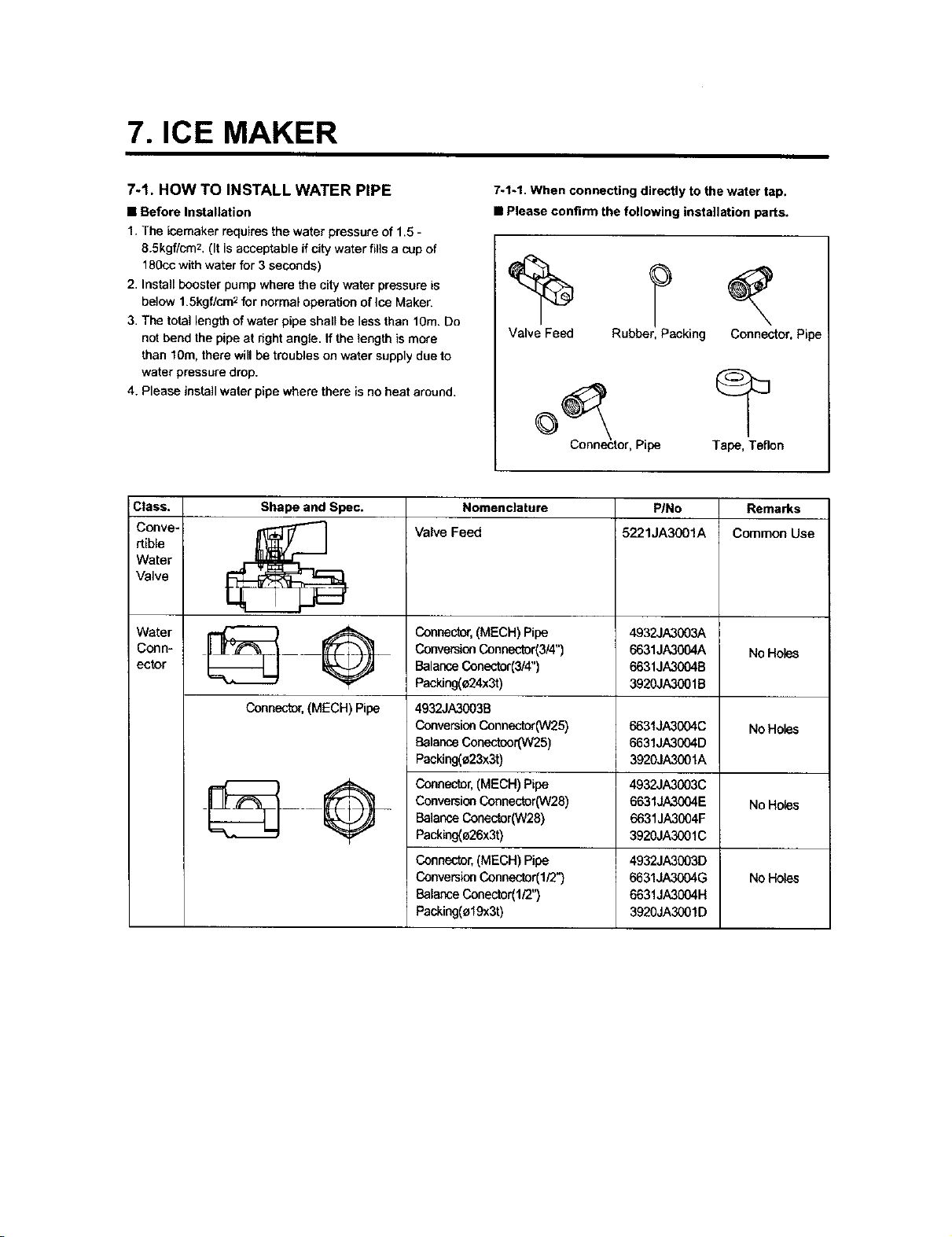
7. ICE MAKER
7-1. HOW TO INSTALL WATER PIPE
• Before Installation
1. The icemaker requires the water pressure of 1.5 -
8.5kgf/cm 2, (It is acceptable if city water fills a cup of
lfl0co with water for 3 seconds)
2. Install booster pump where the city water pressure is
below 1.5kgf/cm 2for normal operation of Ice Maker.
3. The total length of water pipe shall be less than 10m. Do
not bend the pipe at right angle. If the length is more
than 10m, there will be troubles on water supply due to
water pressure drop.
4. Please install waler pipe where there is no heat around.
7-1-1. When connecting directly to the water tap.
• Please confirm the following installation parts.
Valve Feed Rubber, Packing Connector, Pipe
Connector, Pipe Tape, Teflon
Class. Shape and Spec. Nomenclature P/No Remarks
Conve- (_ Valve Feed 5221JA3001A Common Use
rtible
Water
Valve
Water _ Q Connector, (MECH) Pipe 4932JA3003A
Corm- _____ Conversion Connector(3/4") 6631JA3004A No Holes
ector Balance Conector(3/4") 6631JA3004B
Packing(e24x3t) 3920JA3001B
Connector, (MECH) Pipe
NO Holes
4932JA3003B
ConversionConnector(W25)
BalanceConectcor(W25)
Packlng(e23x3t)
6631JA31304C
6631JA3004D
3920JA3001A
Connector,(MECH)Pipe 4932JA3003C
ConversionConnector(W28) 6631JA3004E No Holes
BalanceConector(W28) 6631JA3CO4F
Packing(a26x3t) 3920JA3001C
No Holes
Connector,(MECH)Pipe
ConversionConnector(I/2")
BalanceConector(1/2")
Packing(_19x3t)
4932JA3003D
6631JA3004G
6631JA3004H
3920JA3001D
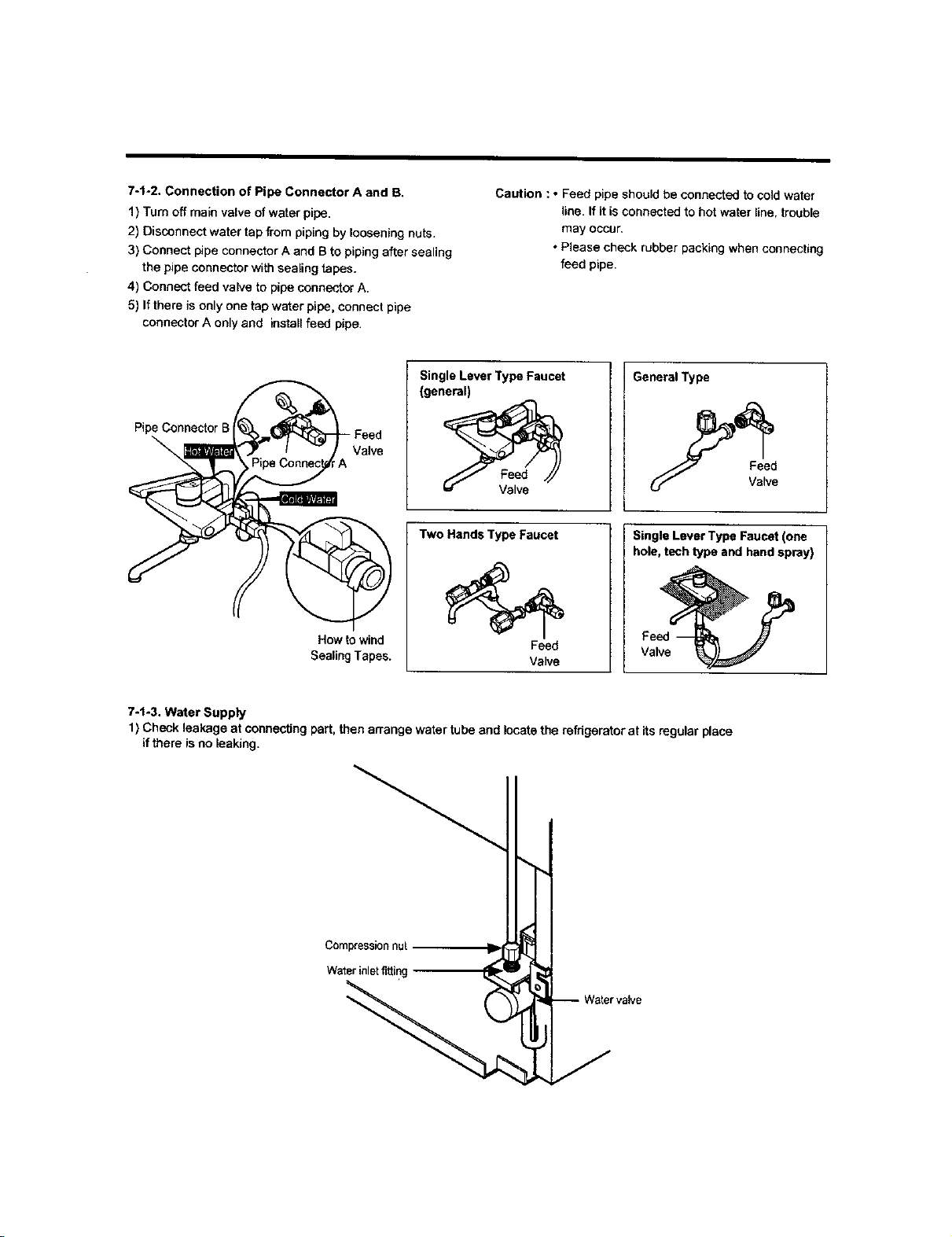
7-t-2. Connection of Pipe Connector A and B.
1) Turn off main valve of water pipe.
2) Disconnect water tap from piping by loosening nuts.
3) Connect pipe connector A and B to piping after sealing
the pipe connector with sealing tapes.
4) Connect feed vaF/e to pipe connector A.
5) If there is only one tap w_er pipe, connect pipe
connector A only and install feed pipe.
Caution : • Feed pipe should be connected to cold water
line. If it is connected to hot water line, trouble
may occur.
• Please check rubber packing when connecting
feed pipe.
Pipe Connector
\
Valve
How to wind
Sealing Tapes.
Single Lever Type Faucet
(general)
Two Hands Type Faucet
Feed
Valve
General Type
Single Lever Type Faucet (one
hole, tech type and hand spray)
Feed
Valve
7-1-3. Water Supply
1) Check leakage at connecting part, then arrange water tube and locate the refrigerator at its regular place
if there is no leaking.
I
Compression nut
Water inletfitting
Water valve
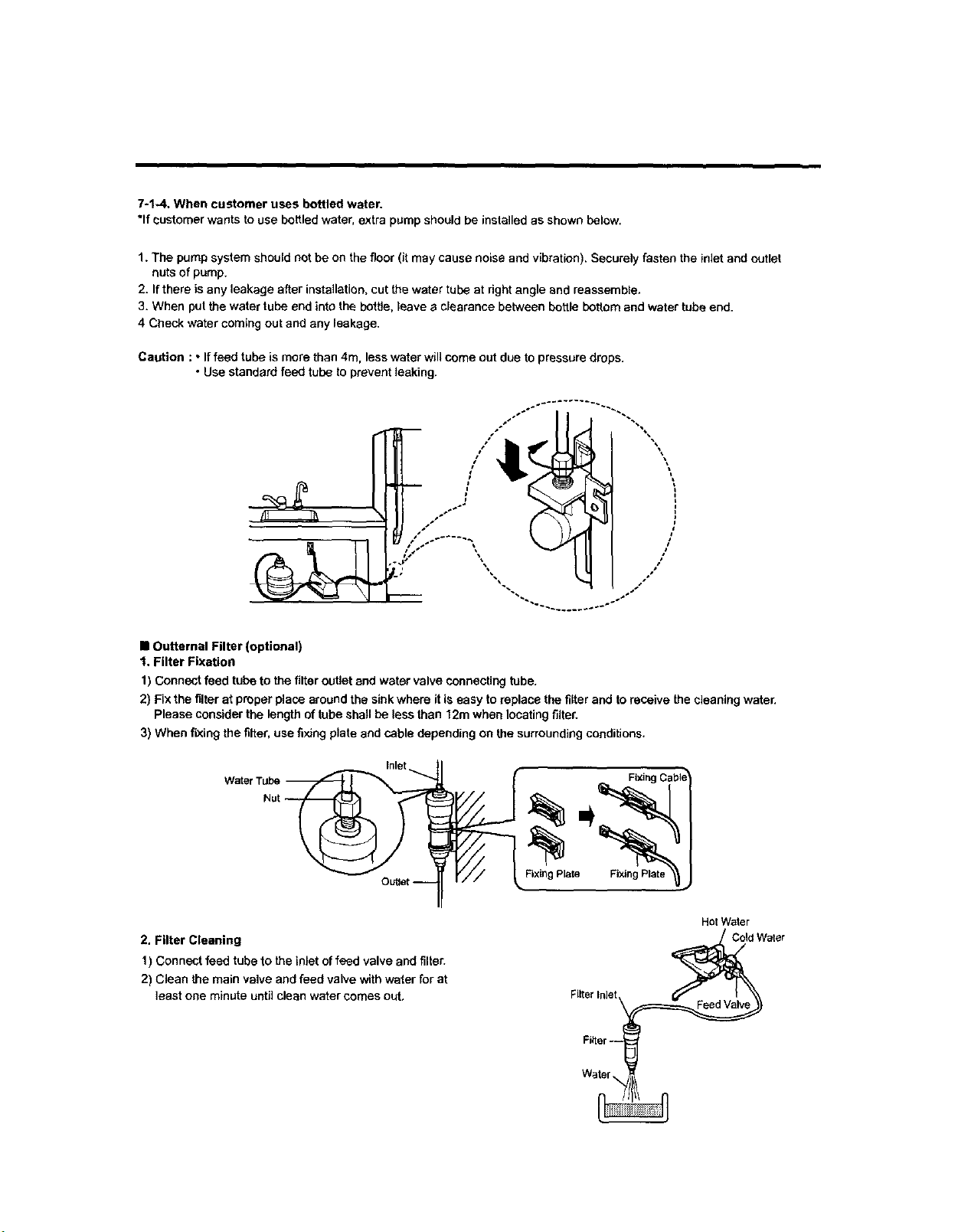
7-1,.4, When customer uses bottled water.
*If customer wants to use bottled water, extra pump should be installed as shown below.
1. The pump system should not be on the floor (it may cause noise and vibration). Securely fasten the inlet and outlet
nuts of pump.
2. If there is any leakage after installation, cut the water tube at dght angle and reassemble,
3. When put the water tube end into the botfie, leave a clearance between bottle beftom and water tube end.
4 Check water coming out and any leakage.
Caution : • If feed tube is more than 4rn, less water will come out due to pressure drops.
• Use standard feed tube to prevent leaking.
\
• Outternal Filter (optional)
1. Filter Fixation
1) Connect feed tube to the filter outlet and water valve connecting tube.
2) Fix the filter at proper place around the sink where it is easy to replace the filter and to receive the cleaning water.
Please consider the length of tube shall be less than 12m when locating filter.
3) When fixing the filter, use fixing plate and cable depending on the surrounding conditions.
WatE
FixingPlam Fixing Plate
2. Filter Cleaning
1) Connect feed tube to the inlet of feed valve and filter.
2) Clean the main valve and feed valve with water for at
least one minute until clean water comes out,
Hot Water
Cold Water
Filter Inlet
Fi_er_
Water
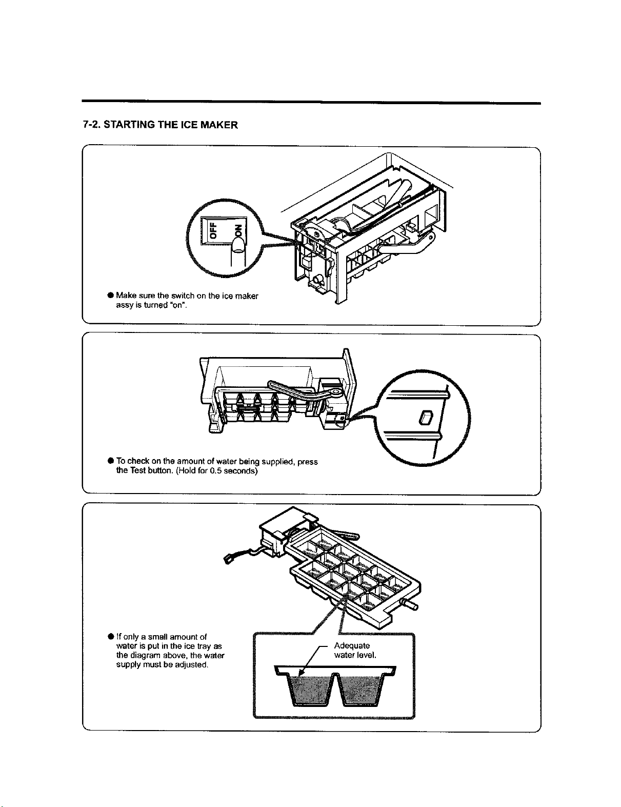
7-2, STARTING THE ICE MAKER
• Make sure the switch on the ice maker
assy is turned "on".
• To check on the amount of water being supplied, press
the Test button. (Hold for 0,5 seconds)
• if only a small amount of
water is put in the ice tray as
the diagram above, the water
supply must be adjusted.
Adequate
water level.
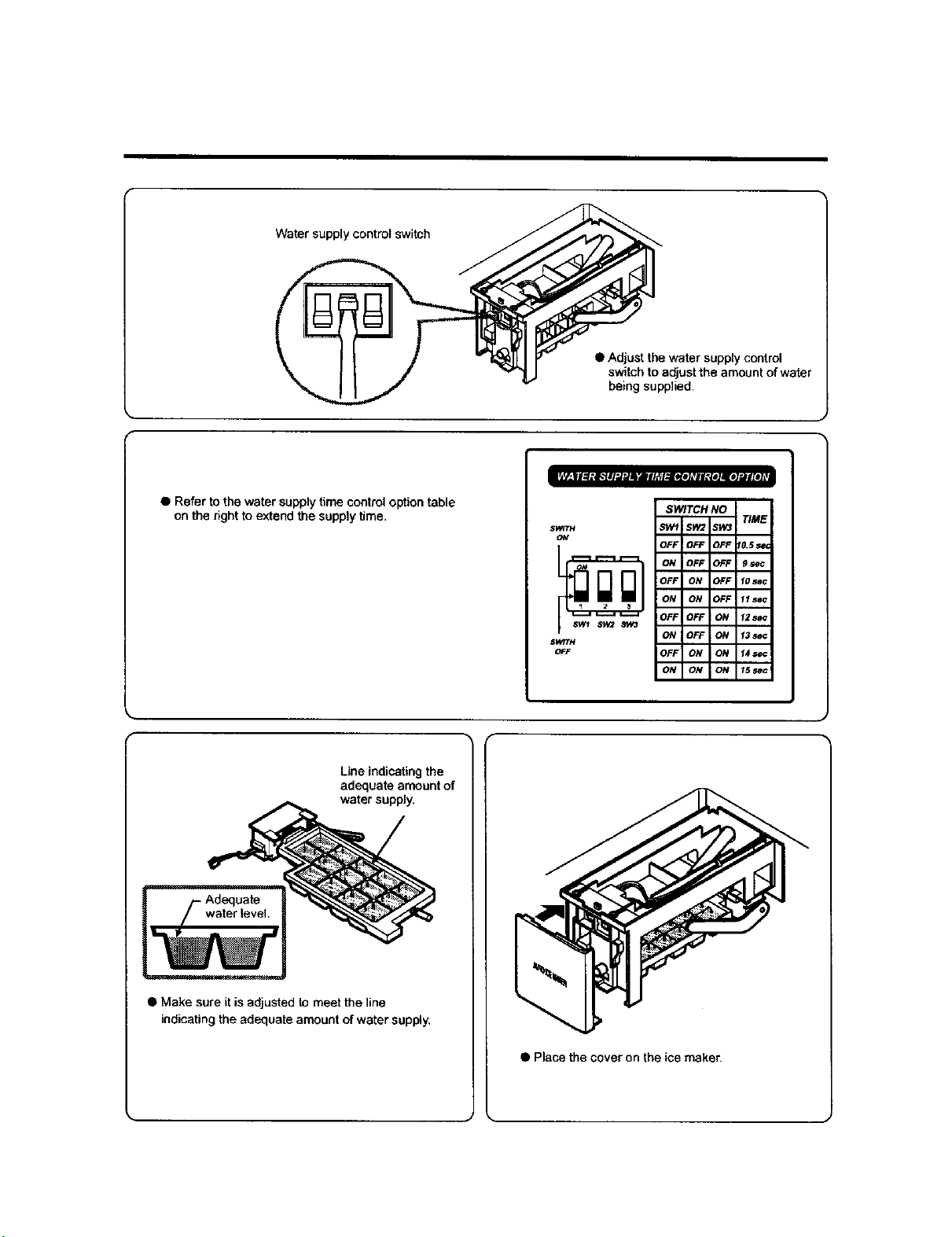
Watersupplycontrolswitch
• Adjustthewatersupply control
switch to adjust the amount of water
being supplied.
• Referto the watersupplytime control option table
on the rightto extendthe supplytime.
SPRTH
ON
SWITH
OFF
SWITCH NO
Line indicating the
adequate amount of
water supply.
• Make sure it is adjusted to meet the line
indicating the adequate amount of water supply,
• Place the cover on the ice maker.
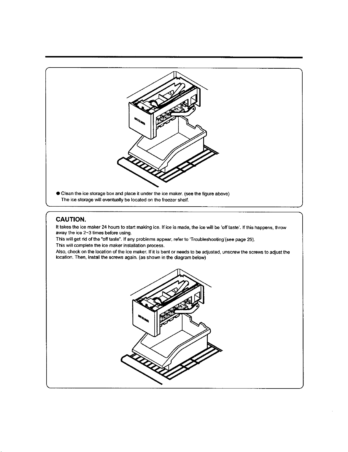
• Clean the ice storage box and place it under the ice maker. (see the figure above)
The ice storage will eventually be located on the freezer shelf.
CAUTION.
It takes the ice maker 24 hours to start making ice. If ice is made, the ice will be 'off taste'. If this happens, throw
away the ice 2-3 times before using.
This will get rid of the "off taste". If any problems appear, refer to 'Troubleshooting'(see page 25).
This will complete the ice maker installation process.
Also, check on the location of the ice maker. If it is bent or needs to be adjusted, unscrew the screws to adjust the
location, Then, install the screws again. (as shown in the diagram below)
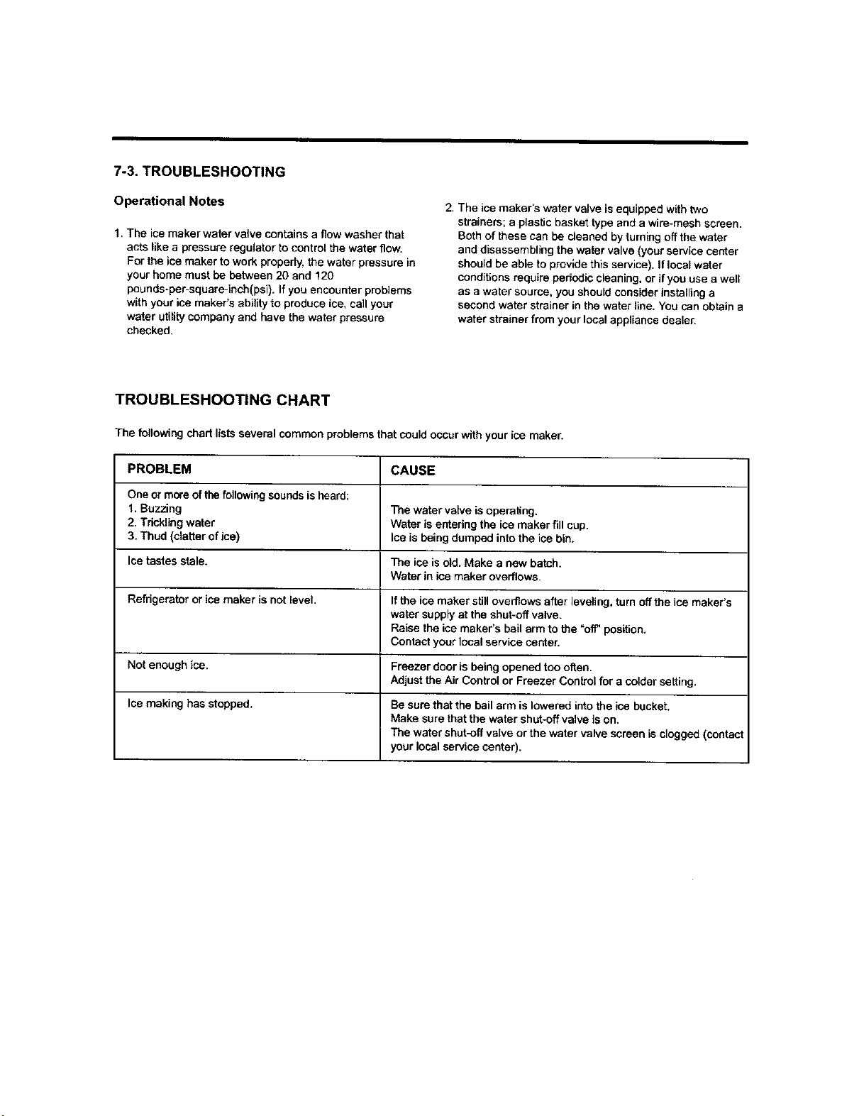
7-3. TROUBLESHOOTING
Operational Notes
1, The ice maker water valve contains a flow washer that
acts like a pressure regulator to control the water flow.
For the ice maker to work properly, the water pressure in
your home must be between 20 and 120
pounds-per-square-inch(psi). If you encounter problems
with your ice maker's ability to produce ice, call your
water utility company and have the water pressure
checked.
2. The ice maker's water valve is equipped with two
strainers; a plastic basket type and a wire-mesh screen.
Both of these can be cleaned by turning off the water
and disassembling the water valve (your service center
should be able to provide this service). If local water
conditions requ[ra pedodic cleaning, or if you use a well
as a water source, you should consider installing a
second water strainer in the water line. You can obtain a
water strainer from your local appliance dealer.
TROUBLESHOOTING CHART
The following chart lists several common problems that could occur with your ice maker.
PROBLEM CAUSE
One or more of the following sounds is heard:
1, Buzzing The watar valve is operalJng.
2. Trickling water Water is entering the ice maker fill cup.
3. Thud (clatter of ice) Ice is being dumped into the ice bin,
Ice tastes stale. The ice is old. Make a new batch.
Water in ice maker overflows.
Refrigerator or ice maker is not level. If the ice maker still overflows after leveling, turn offthe ice maker's
water supply at the shut-off valve.
Raise the ice maker's bail arm to the "off" position.
Contact your local service can_er.
Not enough ice. Freezer door is being opened too often.
Adjust the Air Control or Freezer Control for a colder setting.
Ice making has stopped. Be sure that the bail arm is lowered into the ice bucket.
Make sure that the water shut-off valve is on.
The water shut.off valve or the water valve screen is clogged (contact
your local service center).
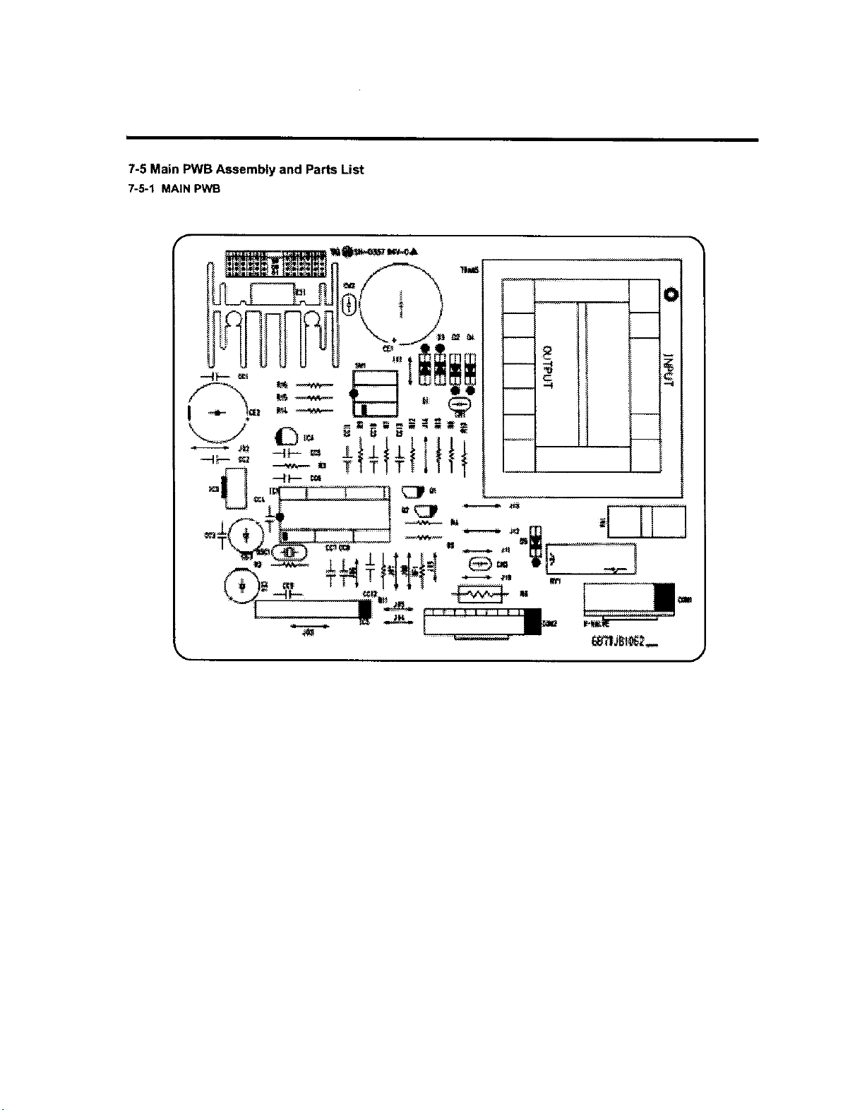
7-5 Main PWB Assembly and Parts List
7-5-1 MAIN PWB
f
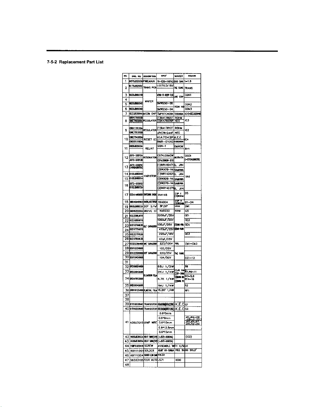
7-5-2 Replacement Part List
NO. _ NO. _a _C' MAKER
1 _870JB20_ P_'J_MNN R-l(0_-1107A 1)00 _ k-1,6
2 _170,F9200_ TR_NS F'_ h:117V'O_lSV IkE _ PRANS
4
-- WAFER
5 _ ;MW2_O--OU
CON2
-- _ON H(
6 _ ;MW250--04 C_N3
7 01ZZJB200_MICO__p r_P87C4Ogh 1_J4BA IC1('_
9 01RhlTB12....._IREGt_J_TOR 11)8A178121 ROHM IC2
_8120a JPC7Bt2AHF NEC
01KE7_200_ <LA7042F K.E*C
10 m _ES_ETIC i¢€
0_*O010100_ _MR--OIOt C Km
Bg_,JB2Q03, GSN--1 OMRON
11 m RELAY RYI
3_
1 2 --2570-0g01__E_ONA]Q_ --_ST4"0OUG_B4JRATk QSCl
J570-g061Z ::_€.0_K1_-TR (-8Z1_
17"/_O_011 1)1N1_40471IL JPN
13 m
:2)5_C471D-H_Sk.MH'#A
14, 6102.1J0011 :1_NR14D62¸ IL .JIN
q /ARISTOR VA1
15 61mJB_, 12_21P-_U S_
,es72-00_Olt '1_VC2710-.14_
168
610_JB_0_ _2_NR1402T IL J_N
1 ¢
17 ¢0_1',_€_G II1OI_IOE tN4148 12_o_u D5
_ly c
IB _ _ 1N4OO4 f_l, O1-04
19 t_6,1Be00_ )£p S/V 3P,DIP OT_X 5Wl
2C O_BZ22OOA]RIVE 1C BA8222 KO_ IC,5
21 O_FJ2M,I_8 Z20OuF/35_ C_E_
22 o_omHms _ cF.2
24 0(Z4771H618 _ _./_lgll --
2_ O(F_271F6_ 22C_J_/16'_ CE3
2_ _E€_11_ 47uF/25V
2_ OC_ _'cZtKl_ 223/100v s_. C_1~C_3
31
3_ _ S_J _/2_ R8
i_Joyk
_ RD2_I_Qe 2KJ 1/4_ 2)1(.01_
_Bo4 R_
R0€_1_ 4.7K 1/4._ _R R3"5.8
_11__ R14._16
RD1_04_08 _MJ 1/4_ R2
Rf116tZG4_ _IAL Flzk16._,F 1/4¥ RF1
3.=
3_
33
3_
0.6*5ram
O.6*8rnm _et__JOIJ06
41 _3807015 JUMp_1_ O.6*lOmm
0*6"12.Stun
O.6*15mm
4_ 5_F03_418SCREW ASSEMBLE_1 H/_
_-_ _911T001 _ _ KR-t_J_MA"_EES IGSOLD"
€6 _9111004 _Bl_lb_ HS3A
47 _9333105 _UX AUT( JS71 KOXI
¢8
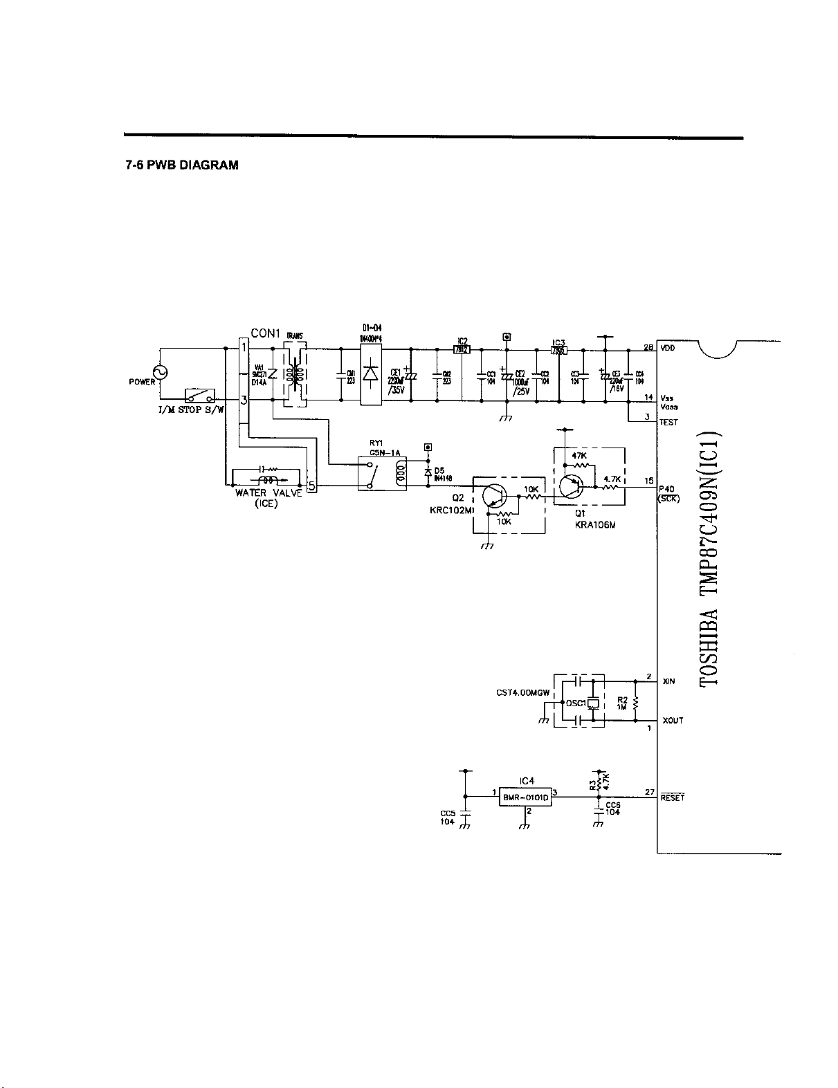
7-6 PWB DIAGRAM
1/1_ STOP S
CON1
WATER
OCE)
KRCIO2Mt
4.7)( I
Q1
KRAIO6M
1 IC# 3 CC6
XIN
XOUT
RESET
L>
Z
L'--
0
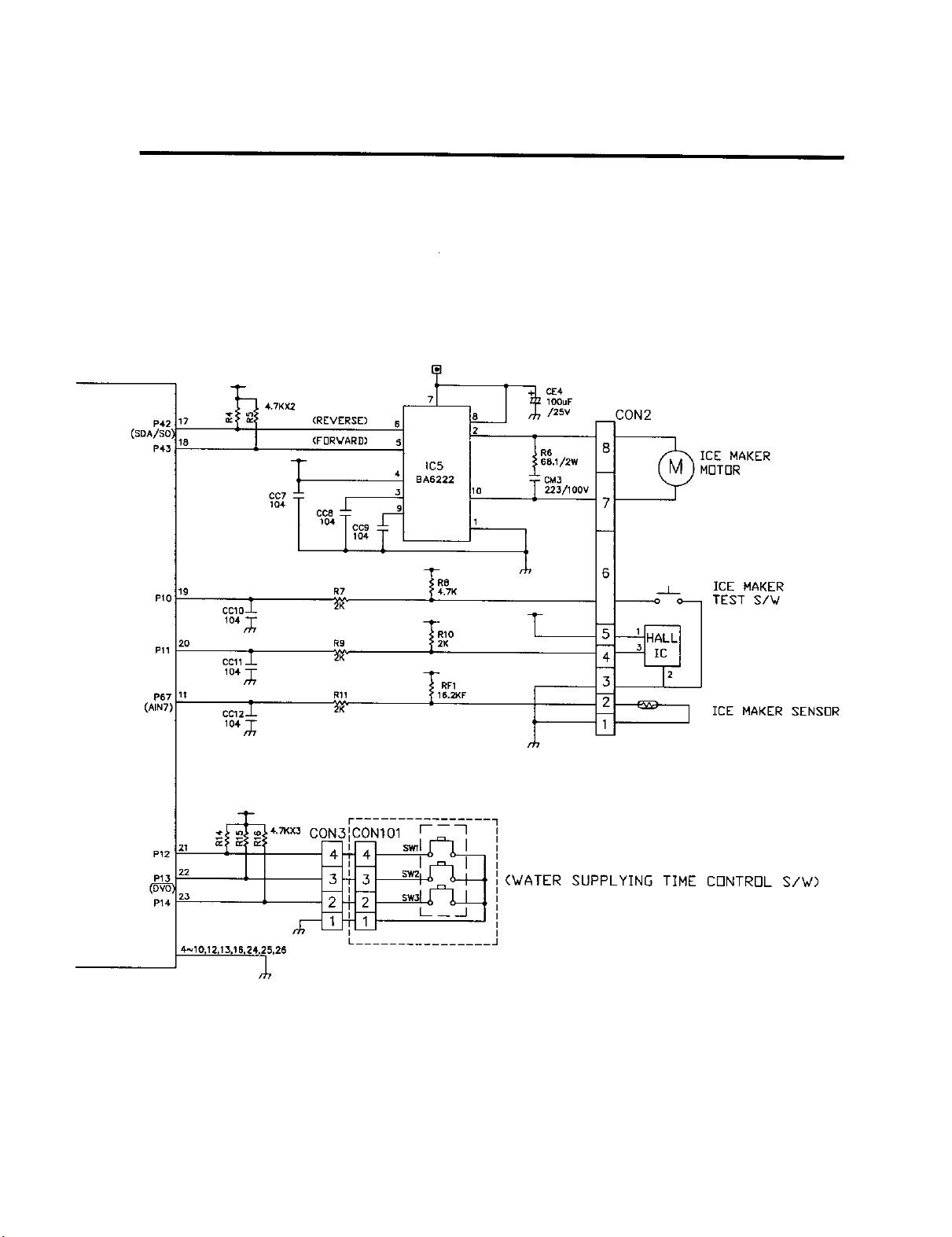
P4;
(SDA/SO I
P43
PIO
Pll
P67
(AIR7)
P12
P14
17
18
Ig
2O
CC10_-
104m_
4.7KX2 /25V
(REVERSE) 6 2
4 CM3
104 TCC91CC9
R7 .7K
#,o t__
R9 K
_-
CC11_-
RF1
Rll 6.2KF
lO&/_/
CON2
8
7
6
i
3
Z
ICE MAKER
MOTBR
_j_ ICE MAKER
TEST S/_
ICE MAKER SENSOR
_*>_t-_ 4.7Kx3 CON3FCONI01 I ]
22
23
L
4_10.12,13,16,24,25,26
(WATER SUPPLYING TIME CONTROL S/W)
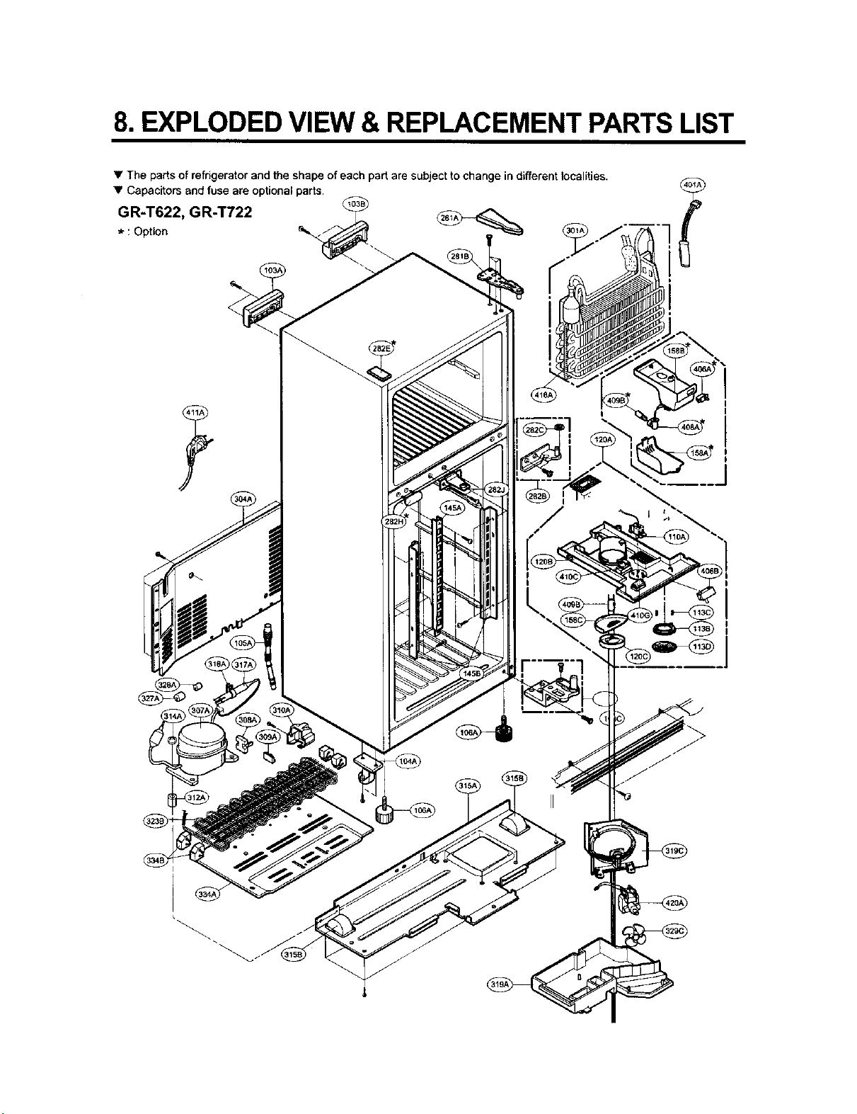
8. EXPLODED VIEW & REPLACEMENT PARTSLIST
• The parts of refrigerator and the shape of each part are subject to change in different localities.
• Capacitors and fuse are optional parts.
GR-T622, GR-T722
* : Option _ _
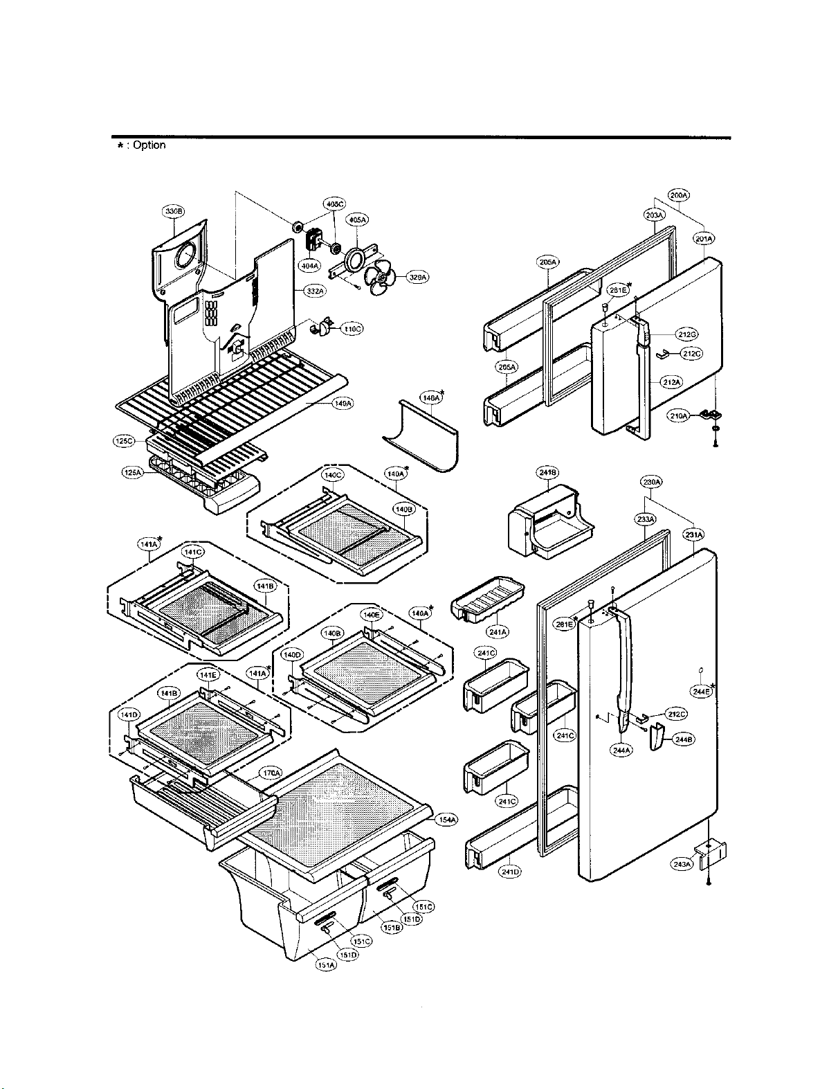
: Option
! \

ICE MAKER PART
* :Option
I
>