Loading ...
Loading ...
Loading ...
9
INSTALLATION (cont.)
e. Starting with the barbecue burner valve in the OFF
position, turn the gas supply on. Carefully, check all
gas connections for leaks with a brush and soapy
water before lighting.
NEVER USE A MATCH OR OPEN FLAME TO TEST FOR
LEAKS.
f. Refer to the AIR SHUTTER ADJUSTMENT section
before replacing barbecue control panel and knobs.
4. INSTALL THE FLAVOR GRID
a. Place the fl avor grid directly on the burners. Make
sure the legs (on the underside) of the grid rests on
the burners (Fig. 9-3), centering the grid over the
burners with the open side up. This allows heat from
the burners to be evenly distributed throughout the
cooking area. The fl avor grid heats and cools quickly,
making the Fire Magic barbecue very responsive to
the changes you specify in grill temperature.
The fl avor grid is made of stainless steel and is rust resistant.
It may be cleaned with standard oven cleaners.
d. Change all orifi ces if necessary, following instructions
provided with the replacement orifi ces (furnished with
all Fire Magic gas barbecues).
e. After checking orifi ce drill size, carefully replace the
burners on the pegs so the brass orifi ce and orifi ce
holder fi ttings project well into the burners. The air
shutter springs and air shutters should be installed over
the orifi ce holder fi tting, between the burner and the
pipe manifold, in the order and in the position pictured
below (
Fig. 9-1).
3. CONNECT THE GAS SUPPLY TO BARBECUE
a. A C.S.A. approved stainless steel fl ex connector will
be needed to bring the gas supply from the gas line
stub to the valve manifold. A
1
/
2
" (1.3 cm) x 24" (61
cm) fl ex stainless steel connector is suitable for most
installations. A
1
/
2
" (1.3 cm) female fl are fi tting is required
to connect to the unit. ONLY LISTED STAINLESS
STEEL CONNECTORS should be used to connect the
barbecue to the gas line inside the enclosure.
CAUTION: Use only stainless steel fl ex connectors that
are C.S.A. listed.
WARNING: A rubber or plastic connector will rupture or leak,
resulting in an explosion or serious injury if used
inside the barbecue enclosure.
b. Verify that the gas supply is turned off. Then connect
the
1
/
2
" (1.27 cm) pipe adapter fi tting supplied with the
stainless steel fl ex connector to the gas supply stub.
Use pipe joint compound that is resistant to all gasses
on the male pipe fi tting and tighten securely. Do not
use pipe joint compound to connect the fl are fi ttings.
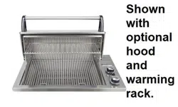
c. Lower the barbecue into place, making sure not to
pinch or kink the gas connector. The unit will rest on
the counter (Fig. 9-2).
d. Connect the fl ex connector to the fl are fi tting on the
manifold inlet. Support the manifold inlet fi tting with
a wrench to avoid applying excessive torque to the
manifold assembly while tightening this connection
securely. Do not use pipe compound on fl are fi ttings.
Fig. 9-2
Fig. 9-3
AIR SHUTTER
BURNER
MANIFOLD WITH
ORIFICE HOLDER
BURNER
ORIFICE
SPRING
BURNER NECK
BURNER CLIP
Burner
Burner neck
Spring
Burner
manifold with
orifi ce holder
Orifi ce
Air shutter
Burner clip
Fig. 9-1
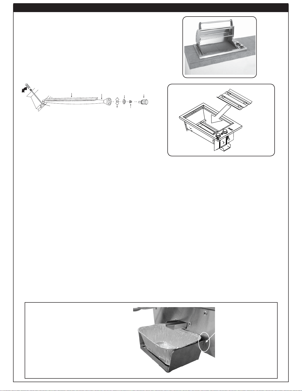
DRIP COLLECTOR INSTALLATION
HOOK DRIP
COLLECTOR TRAY
INTO SLOTS
AND PUSH DOWN.
PLACE DRIP
RECEPTACLE ON
TRAY
Fig. 9-4
The drip collector is located below the manifold
(see Parts List). To gain access to this area in
order to empty or change the drip receptacle,
a small access door in the barbecue island or
enclosure is required.
To install the drip collector, place the hooks of the
collector tray into the slots (located at the bottom
of the barbecue, below the manifold). Press down
to fasten securely. Place the drip receptacle on
the tray below the drip chute (Fig. 9-4).
Hook the drip
collector tray into
the slots and push
down. Place the drip
receptacle on tray.
Important: Check and clean the drip
tray after each use.
Loading ...
Loading ...
Loading ...