Loading ...
Loading ...
Loading ...
8
COUNTER TOP
RIGHT
14" MIN.
10" MAX.
Fig. 8-2
View from
Front
This barbecue is designed for outdoor use only.
DO NOT use this unit under unprotected fl ammable
surfaces. DO NOT use this appliance inside a building,
garage, or any other covered area (see EXHAUST
REMOVAL). DO NOT use this barbecue in or on a
recreational vehicle or boat.
WARNING
Built-in models must be installed in masonry or other type of
fi reproof enclosure, unless an insulating liner is purchased
from the manufacturer. The unit alone is not insulated, and
therefore must be installed with 18" (45.7 cm) of side, front,
and back clearance from unprotected combustible materials,
such as wood, plastic, or stucco with wood framing.
This barbecue must be installed so that it can be removed in
the event service should be necessary. Any protrusion into the
barbecue enclosure from either side, which is less than 14"
from the countertop, may obstruct the frame and prevent the
unit from dropping into place (see GAS SUPPLY PLUMBING
REQUIREMENTS)
EXHAUST REMOVAL
If installed under a patio roof, the cooking grid area should
be fully covered by a chimney and exhaust hood. An exhaust
fan with a rating of at least 1,000 CFM (472 liters per second)
is necessary to effi ciently remove smoke and other cooking
by-products from the covered area. This barbecue shall not be
used under unprotected overhead combustible construction.
Do not install in a fully enclosed area of any kind.
GAS SUPPLY PLUMBING REQUIREMENTS
Rigid
1
/
2
" (1.3 cm) black steel pipe is required to conduct the
gas supply into the barbecue enclosure for connection to
the unit. Where required, use pipe joint compound which is
resistant to all gases should be applied to all male fi ttings and
all joints tightened securely. Do not use pipe joint compound
to connect fl are fi ttings.
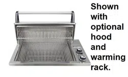
The pipe should terminate near the right rear of the enclosure,
no more than 10" (25.4 cm) from the counter top. Installation
will be simplifi ed if the pipe enters the enclosure vertically
from the bottom and no more than 6" (15.2 cm) from the right
side or rear wall (Fig. 8-1).
If the pipe does not come up against the right wall, it can
easily be run along the enclosure fl oor and turned up to rise
within 10" (25.4 cm) of the counter top, against right wall
(leaving space only to connect fi ttings,
Fig. 8-2).
Perform the following checks before installing the
barbecue:
1. CHECK FUEL ORIFICES FOR PROPER SIZE
Fire Magic barbecues are equipped with orifi ces for
natural gas unless otherwise indicated. For use with
propane gas, smaller orifi ces must be installed to
avoid hazardous overheating.
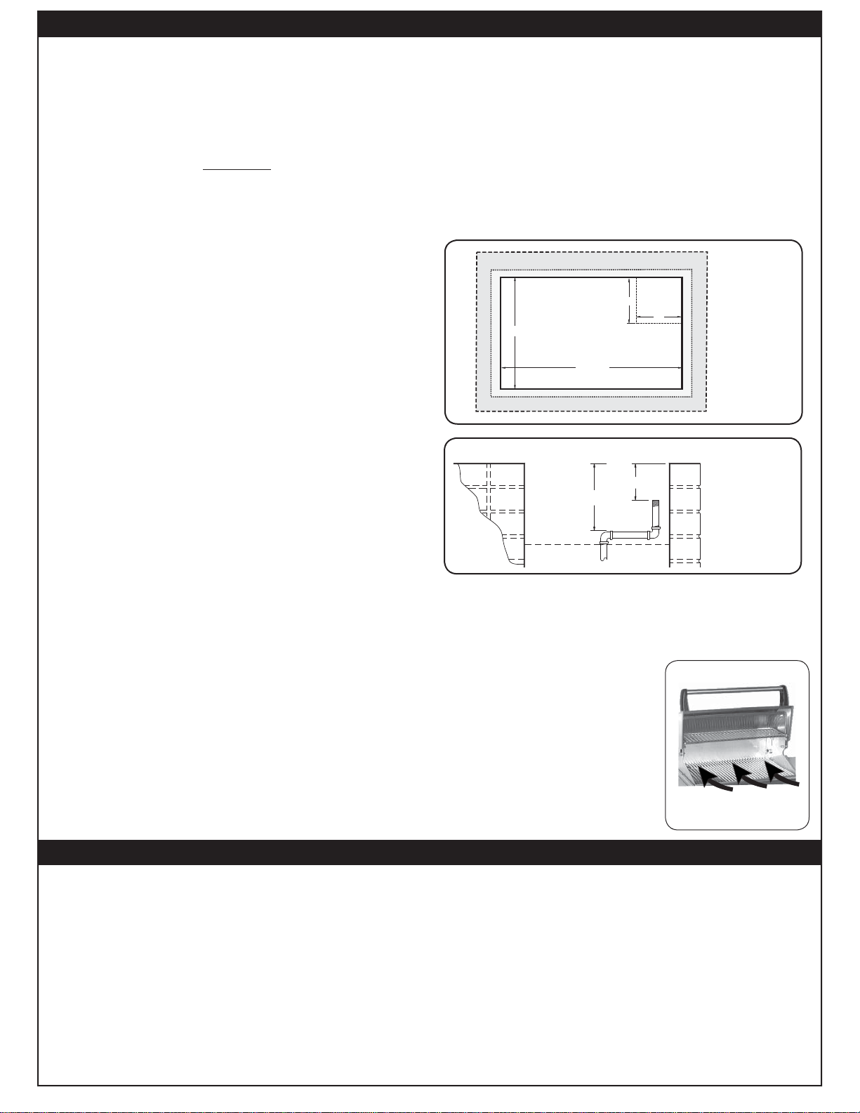
2. IF YOU ARE NOT SURE YOU HAVE THE CORRECT
BARBECUE BURNER ORIFICE SIZE
a. Remove the cooking grids and fl avor grid from the
barbecue, and where fi tted, the oven/hood.
b. If the gas supply has been connected, make sure the
burner valve is in the OFF position. Then pull the knobs
from their stems. Lift the drop-in top and remove it from
the barbecue. You will need to pull up on the corners to
release the top from spring clips.
c. Check the orifi ce size by removing the burner clips
and pulling the burner away from the orifi ce. The drill
size is stamped on the face of each orifi ce. Be sure
not to lose the air shutter or air shutter spring, which
may become detached when the burner is removed.
(Refer to Table 1 for correct orifi ce size).
CAUTION: An external valve in the gas line is
necessary for safety when the barbecue is
not in use. It also provides for convenient
maintenance and repair. A removable key
is recommended.
GAS SUPPLY AND MANIFOLD PRESSURE
Natural Gas - Normal 7" (17.8 cm) Water Column, Minimum
5" (12.7 cm), Maximum 10
1
/
2
" (26.7 cm).
Propane Gas - Normal 11" (27.9 cm)Water Column, Minimum
8" (20.3 cm), Maximum 13" (33 cm).
INSTALLATION
BACK OF ENCLOSURE
FRONT OF ENCLOSURE
STUB OUT
GAS PIPE
ANYWHERE IN
THIS AREA
FOOTPRINT OF DROP-IN TOP
ENCLOSURE OPENING
BBQ DROPS IN HERE
16 1/2"
29 1/2"
TOP SURFACE OF ENCLOSURE
Fig. 8-1
Top View
PLANNING FOR INSTALLATION
CAUTION: Wind blowing into or across the rear oven lid vent
can cause poor performance and/or dangerous
overheating. Orient the grill so that the prevailing
wind blows toward the front of the grill (Fig. 8-3).
CAUTION: To prevent dangerous
overheating, the rear
of the unit must have a
minimum clearance of
8” from any backsplash/
wall.
Fig. 8-3
CORRECT
Place grill so prevailing wind
blows toward front of grill
Loading ...
Loading ...
Loading ...