Loading ...
Loading ...
Loading ...
RVICE AN
TO LEVEL MOWER HOUSING
Adjust the mower while tractor is parked on level ground or
driveway. Make sure tires are properly nflated (See
"PRODUCT SPECl FICATION S" on page 3 of this manual).
Iftires are over or underinflated, you will not properly adjust
your mower.
SIDE-TO-SIDE ADJUSTMENT (See Figs. 21 and 22)
• Raise mower to its qighest position.
° At the midpoint of both sides of mower, measure height
from bottom edge of mower to ground, Distance "A" on
both sides of mower should be the same or within 1/4"
of each other,
,, if adjustment is necessary, make adjustment on one
side of mower only,
- To raise one side of mower, tighten lift link adjustment
nut on that side.
° To lower one side of mower, loosen lift link adjustment
nut on that side.
NOTE: Each full turn of adjustment nut will change mower
height about 1/8".
- Recheck measurements after adjusting.
BOTTOM EDGE BOTTOM EDGE
OF MOWER TO OF MOWER TO
GROUND GROUND
/
LIFT LINK
ADJUSTMENT NUT
GROUND LINE
FIG. 21
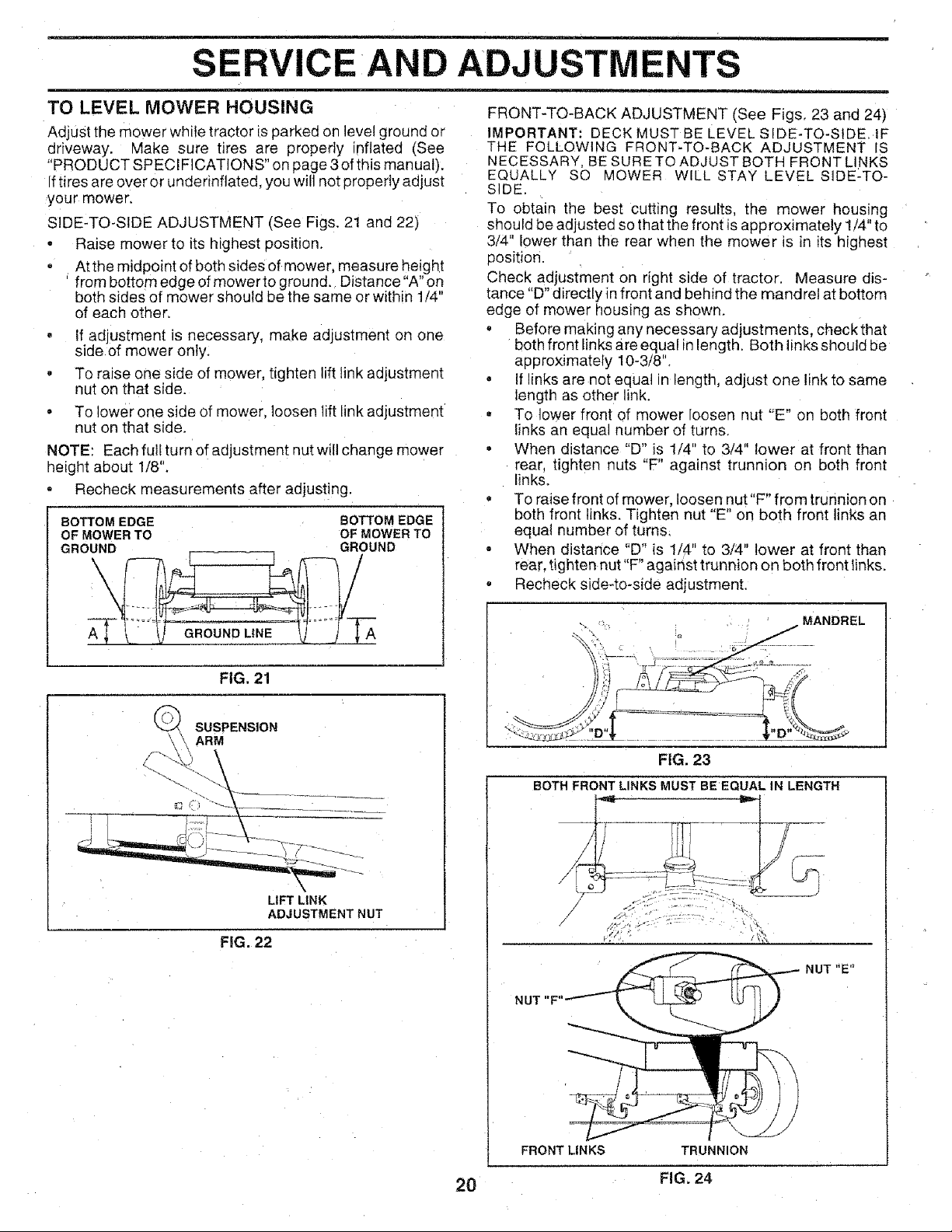
FRONT-TO-BACK ADJUSTMENT (See Figs, 23 and 24)
IMPORTANT: DECK MUST BE LEVE_ SIDE-TO-SIDE. IF
THE FOLLOWING FRONT-TO-BACK ADJUSTMENT IS
NECESSARY, BE SURE TO ADJUST BOTH FRONT LINKS
EQUALLY SO MOWER WILL STAY LEVEL SIDE-TO-
SIDE.
To obtain the best cutting results, the mower housing
should be adjusted so that the front is approximately 1/4" to
3/4" lower than the rear when the mower is in its nighest
posit_on.
Check adjustment on right side of tractor, Measure dis-
tance "D" directly in front and behind the mandrel at bottom
edge of mower housing as shown.
o Before making any necessary adjustments, check that
both front links are equal in length. Both links should be
approximately 10-3/8".
• if inks are not equal n length, adjust one link to same
length as other link,
• To lower front of mower loosen nut "E" on both front
Einksan equal number of turns.
• When distance "D" is 1/4" to 3/4" lower at front than
rear, tighten nuts "F" against trunnion on both front
links.
• To raise front of mower, loosen nut "F" from trunnion on
3oth front links. Tighten nut "E" on both front links an
equal number of turns.
- When distance "D" is 1/4" to 3/4" lower at front than
rear. tighten nut"F" against trunnion on both front links.
° Recheck side-to-side adjustment.
SUSPENSION
ARM
FIG. 22
\
MANDREL
FIG. 23
BOTH FRONT LINKS MUST BE EQUAL IN LENGTH
z __: ,
z \'S
NUT "E"
NUT "F"
/l
FRONT LINKS TRUNNION
20 FIG. 24
Loading ...
Loading ...
Loading ...