Loading ...
Loading ...
Loading ...
Part number 550-100-400/0119
31
Field wiring — basic system (continued)
— see the ADVANCED INSTALLATION section of this
manual.
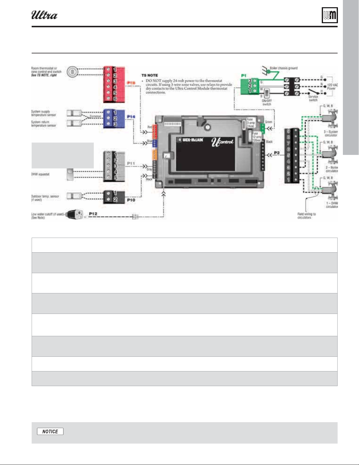
Figure 34 Simpli ed irin asic sstem ith and space heatin see AANC section for more information
ire the tan auastat to the U-Control heat demand input terminals and .
ire the space heatin thermostat or one controller or one ale end sitches across the U-Control heat demand
input terminals and .
Attach a sensor supplied ith oiler to the sstem suppl pipe and ire to terminals and .
Locate sensor in the position shon in pipin diarams on pae throuh pae .]
Attach a sensor supplied ith oiler to the sstem return pipe and ire to terminals and .
Locate sensor in the position shon in pipin diarams on pae throuh pae .]
Install the outdoor temperature sensor supplied ith oiler and ire to terminals and .
ire the circulator supplied installer as circulator folloin instructions on Connect the oiler circulator sup-
plied ith oiler as circulator folloin instructions on pae .
ire the oiler circulator supplied ith oiler as circulator folloin instructions on pae .
ire the sstem circulator supplied installer as circulator folloin the instructions on pae .
Locate the sensors on the system
piping as shown in
Figure 4, page 11
and other piping drawings throughout
this manual.
®
Series 4
gas-fired water boiler — Boiler Manual
Loading ...
Loading ...
Loading ...