Loading ...
Loading ...
Loading ...
Part number 550-100-400/0119
116
Troubleshooting (continued)
Check the following:
1. Make sure thermostat is calling for heat and con-
tacts (including appropriate zone controls) are
closed. Check for 24 VAC between thermostat wire
nuts and ground.
2. Make sure all external limit controls are either
installed (and closed) or temporarily jumpered
for testing.
3. Make sure that connectors to control module are
securely plugged in at module and originating
control.
4. Gas pressures:
Maximum: 13” w.c. with no fl ow (lockup) or
with boiler on
Minimum: 4” w.c. (for all except 5” for
-299/310) for natural gas, or 4” w.c. for propane,
with gas fl owing (verify during startup with
boiler at high fi re)
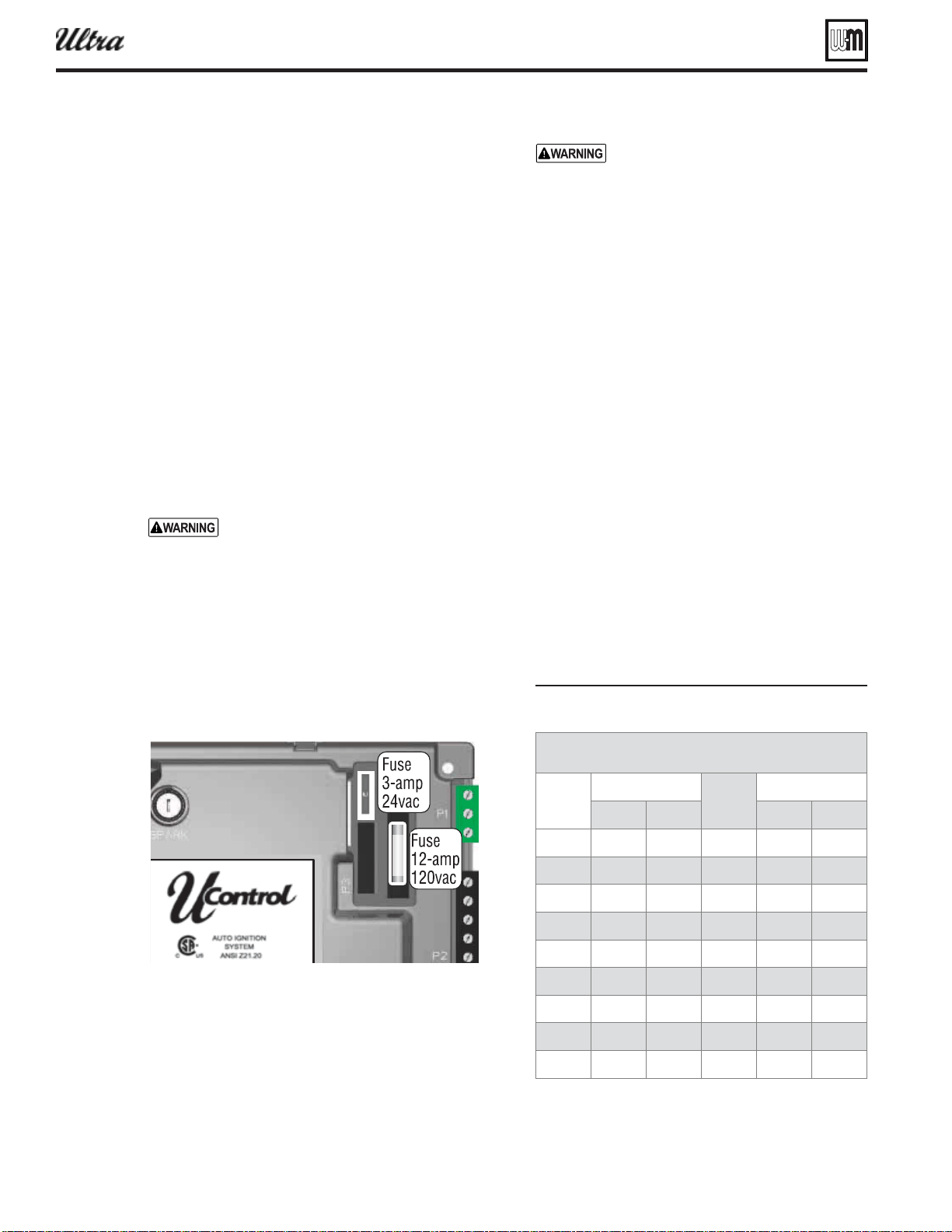
Always check control module fuses
ALWAYS check control module fuses
before replacing control module or any
major components (blower, etc.). If one
of these fuses is blown, it can prevent
control module or other components
from operating.
1. Turn OFF power to boiler at external line switch.
2. Remove jacket door and jacket top panel. Rotate
the swing-away control panel forward to expose
the U-Control module.
3. Remove and inspect the two fuses (located as shown
below).
4. If necessary, replace the fuse:
a. Low voltage circuit fuse is 3-amp fast-blow
(Littelfuse 257003).
b. Line voltage circuit fuse is 12-amp slow-blow
(Littelfuse 326012P).
Do not jumper fuse or replace with any
fuse except as specifi ed. Failure to comply
could result in severe personal injury,
death or substantial property damage.
5. Reinstall jacket top panel and boiler jacket door
after checking the fuses.
6. Restore power to boiler at external line switch and
verify boiler operation after completing boiler
service.
Checking temperature sensors
1. The boiler temperature sensors (flue, outdoor,
return water and supply water) are all resistance-
type devices.
2. Figure 123 shows the correct value for the sensor
at various temperatures.
3. Use the resistance values at 32°F, 60°F, 70°F and
212°F to measure the sensor resistance at known
temperatures (ice point, room temperature and sea
level boiling point). For ice point and boiling point,
insert the sensor in water at that temperature. Use
an ohmmeter to read resistance value.
4. To check whether the control module is correctly
sensing temperature, you can use a resistance de-
cade box. Connect the decade box temporarily in
place of a sensor and read the corresponding tem-
perature on the U-Control display. The temperature
should be close to the value corresponding to the
input resistance.
Figure 123 Sensor resistance alues
®
Series 4
gas-fired water boiler — Boiler Manual
Sensor resistance values
Temp
(°F)
Sensor ohms
Temp
(°F)
Sensor ohms
Min Max Min Max
34265 37871
4517 4992
27834 30764
3698 4088
21630 23907
3043 3364
16944 18727
2517 2782
13372 14780
2091 2311
10629 11747
1744 1928
8504 9399
1461 1615
6847 7568
1229 1359
5545 6129
1038 1147
Loading ...
Loading ...
Loading ...