Loading ...
Loading ...
Loading ...
Page 20 of 57
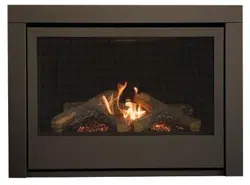
Figure 4
3.3.4 DIRECT VENT INFORMATION / DIRECT VENT D'INFORMATION
The unit must be connected to listed 2-ply aluminium venting, 4” flex vent on the exhaust side and listed 7” flex
vent on the air intake side or can be used with Security Venting, Dura-Vent 4” x 6-5/8” with the use of Dura-
Vent adapters part #’s 0924N3 & P574, Selkirk Direct-Temp Venting with adapter Part #1604247B, ICC
venting with adapter TM-A446 or Metal-Fab direct venting with the use of Metal-Fab adapter part # 4DDA .
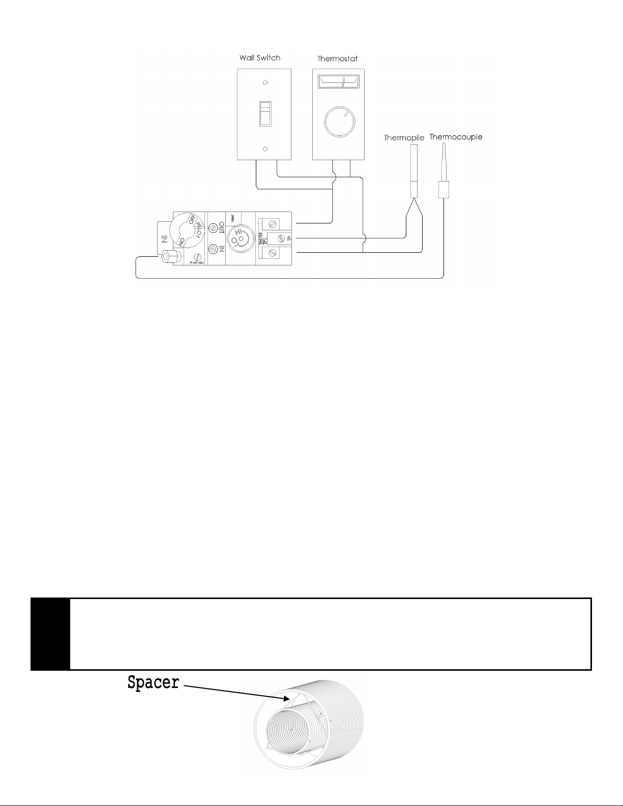
Install the vent components according to the manufacturer's instructions being sure to use spacers (see Figure
5) every 5’ to ensure correct spacing is maintained between air intake and exhaust. Slope horizontal pipe at
least 1/4" (6 mm) rise per foot of horizontal run away from the fireplace. Allow 1" (25 mm) clearance to the
vent. Refer to the graph for allowable vent configurations. Be sure to ensure that termination area allows
enough room for adequate combustion and ventilation air and that the flow of combustion and ventilation air is
not obstructed.
L'appareil doit être connecté à cotée 2 couches d'aluminium ventilation , 4 "flex évent sur le côté de
l'échappement et répertoriés 7 " flex évent sur le côté d'admission d'air ou peut être utilisé avec sécurité
ventilation , Dura-Vent 4 "x 6-5 / 8 " avec l'utilisation d'adaptateurs Dura -Vent 0924N3 & P574 partie les # 's ,
Selkirk Direct -Temp évacuation avec adaptateur partie #1604247B, ICC évacuation avec adaptateur TM-A446
ou Metal-Fab évacuation directe à l'utilisation de Metal-Fab adaptateur partie # 4DDA . Installez les
composants de ventilation selon les instructions du fabricant en veillant à utiliser des entretoises ( voir figure 5)
tous les 5 ' pour assurer un espacement correct est maintenu entre l'apport d'air et l'échappement. Pente tuyau
horizontal d'au moins 1/4 " ( 6 mm ) par pied de course horizontale loin du foyer . Laisser 1 " ( 25 mm) à l'évent
. Reportez-vous au graphique de configuration de l'évacuation admissibles . Veillez à ce que la zone de
terminaison permet assez de place pour combustion et l'air de ventilation et que le débit de combustion et de
l'air de ventilation n'est pas obstruée.
NOTE
If at any time the vent-air intake piping is dismantled, use the vent manufacturer’s
instructions and the sealing instructions for reassembly.
Si à tout moment de la tuyauterie d'admission d'air de ventilation est démontée, utilisez
la ventilation instructions du fabricant et les instructions d'étanchéité pour le
remontage
Figure 5
Loading ...
Loading ...
Loading ...