Loading ...
Loading ...
Loading ...
9
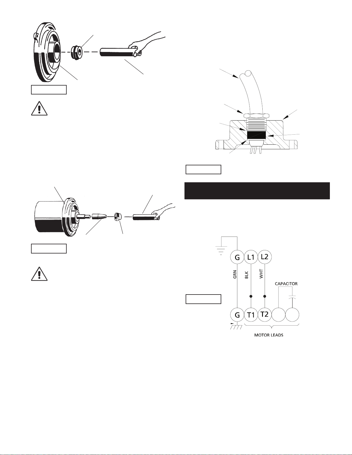
IMPORTANT ! - DO NOT hammer on the seal
pusher- it will damage the seal face.
Slide retaining ring (46d) over shaft and let rest on bearing
(47). Place spring (46c) over shaft and let rest on retaining ring
(46d). Lightly oil ( DO NOT use grease) shaft, bullet and inner
surface of bellows on rotating member (46b), (See Figure 5),
with lapped surface of rotating member (46b) facing outward,
slide over bullet and onto shaft using seal pusher, making sure
spring (46c) is seated in retaining ring (46d) and spring (46c) is
lined up on rotating member (46b) and not cocked or resting on
bellows tail.
IMPORTANT ! - it is extremely important to keep
seal faces clean during assembly. Dirt particles
lodged between these faces will cause the seal to
leak.
Motor - Slide motor rotor with conduit bushing (14), washer
(9), bearing (47) and seal parts (46b, c, d) into seal plate (25)
until bearing (47) seats in seal platel (25). Center washer (9)
on bearing (47) and tighten conduit bushing (14) on seal plate
(25). Lower motor stator over rotor until seated in seal plate
(25), while aligning holes for motor bolts. Insert motor bolts
and torque to 17 inch pounds. Place bracket (15) on one of the
motor bolts. Insert capacitor (3) in bracket (15), attach motor
leads with terminals to capacitor and place terminal boot (27)
over terminals.
Place all motor leads above motor. Position o-ring (42) on seal
plate (25) and lower motor housing (2) over motor and into pilot.
Place socket head cap screws (39) through seal plate (25) into
motor housing (2) and torque to 60 inch pounds. Make wire
connections per paragraph F-3.3. Assemble impeller and volute
per paragraph F-2.2.
F-3.3) Wiring Connections:
Check power cable (10A) on cord grip plate (10j), for cracks or
damage and replace if required (See Figure 6). Bring motor wires
through wire opening in top of housing (2), position square ring
(11) in cord grip plate (10j) and reconnect motor leads to power
cable using connectors (12) as show in Figure 7.
Single Phase, 240 VOLT AC (PSC)
Models 3SF3024L
Green (Ground) Green
Black 1
White 2
Flag connector Capacitor
Flag connector Capacitor
F-3.4) Cord Grip Plate Assembly:
Refi ll with cooling oil as outlined in paragraph F-1.3. Position
cord grip plate (10j) and square ring (11) over opening. Place
lockwashers (4) on cap screws (6), apply thread locking
compound to cap screws (6) threads and torque to 16 ft lbs.
Remove gland nut (10B), friction rings (10C), and grommet
(10D) from cord grip plate (10J) inspect and replace if required
(see Figures 6).
Insert one friction ring (10C), grommet (10D), one friction ring
(10C) and gland nut (10B) into cord grip plate (10J) for power
cable (10A). Torque gland nut (10B) to 15 ft. lbs to prevent
water leakage.
FIGURE 4
FIGURE 5
Rotating Member
(46B)
Motor & Seal Plate
Bullet
Seal Pusher
Gland Nut (10B)
Cord Grip Plate (10J)
Power Cable Assy (10A)
Friction Ring
(10C)
Grommet
(10D)
Friction Ring (10C)
FIGURE 6
Seal Plate (25)
Seal Pusher
Stationary Member
(46A) Polished Face Out
FIGURE 7
Loading ...
Loading ...
Loading ...