Loading ...
Loading ...
Loading ...
8
Position o-ring (42) on volute fl ange and position impeller and
motor housing assembly over studs and onto volute (26).
Apply
thread locking compound to each stud (24). Place lockwasher
(19) and hex nut (20) onto studs (24) and torque to 24 ft. lbs.
Check for free rotation of motor and impeller.
F-3) Motor, Bearing and Seal Service
F-3.1) Disassembly and Inspection:
To examine or replace the motor (1), bearing (47) and shaft seal
(46), disassemble volute and impeller as outlined in paragraph
F-2.1. Drain oil from motor as outlined in paragraph F-1.3.
Position unit upright, using blocks to avoid resting unit on shaft.
After removal of cord grip plate (10j), per paragraph F-1.3, from
motor housing (2) remove cable lead wires from motor lead wires
by disconnecting wire connectors (12). Also disconnect ground
screw (18) from motor (1). The wiring connections should be
noted to insure correct connections when reassembling.
Motor - Remove the motor bolts and lift motor stator from motor
rotor and seal plate (25). Unscrew conduit bushing (14) from
seal plate (25) and lift motor rotor, shaft, bearing (42), rotating
portion of seal (46b), washer (9) and conduit bushing (14) from
seal plate (25).
Check motor capacitor (3, single phase units) with an Ohm
meter by fi rst grounding the capacitor by placing a screwdriver
across both terminals and then removing screwdriver. Connect
Ohm meter (set on high scale) to terminals. If needle moves
to infi nity (∞) then drifts back, the capacitor is good. If needle
does not move or moves to infi nity (∞) and does not drift back,
replace capacitor (3). Inspect motor winding for shorts and
check resistance values. Check rotor for wear. If rotor or the
stator windings are defective, the complete motor must be
replaced.
CAUTION ! - Handle seal parts with extreme care.
DO NOT scratch or mar lapped surfaces.
Seal - Remove rotating member (46a), spring (46c) and
retaining ring (46d) from shaft. (See Figure 3). Examine all
seal parts and especially contact faces. Inspect seal for signs
of wear such as uneven wear pattern on stationary members,
chips and scratches on either seal face. DO NOT interchange
seal components, replace the entire shaft seal (46). If
replacing seal, remove stationary (46a) from seal plate (25) by
prying out with fl at screwdriver.
Bearing - Examine bearing (47) and replace if required. If
replacement is required, remove bearing (47) from motor shaft
using a wheel puller. Washer (9), retaining ring (30) and conduit
bushing (14) can now be removed from motor shaft.
IMPORTANT ! - All parts must be clean before
reassembly.
F-3.2) Reassembly:
Bearing - When replacing bearing, be careful not to damage
the rotor or shaft threads. Clean the shaft thoroughly. Slide
conduit bushing (14) and washer (9) over motor shaft. Insert
retaining ring (30) into groove on shaft. Apply adhesive
compound to the shaft and press bearing (47) on the motor
shaft, position squarely onto shaft applying force to the inner
race of the bearing only, until bearing seats against retaining
ring (30).
Seal - Clean and oil seal cavity in seal plate (25). Press
stationary member (46a) fi rmly into seal plate (25), using a seal
pusher, nothing but the seal pusher is to come in contact with
seal face (See Figure 4). Make sure the stationary member is in
straight.
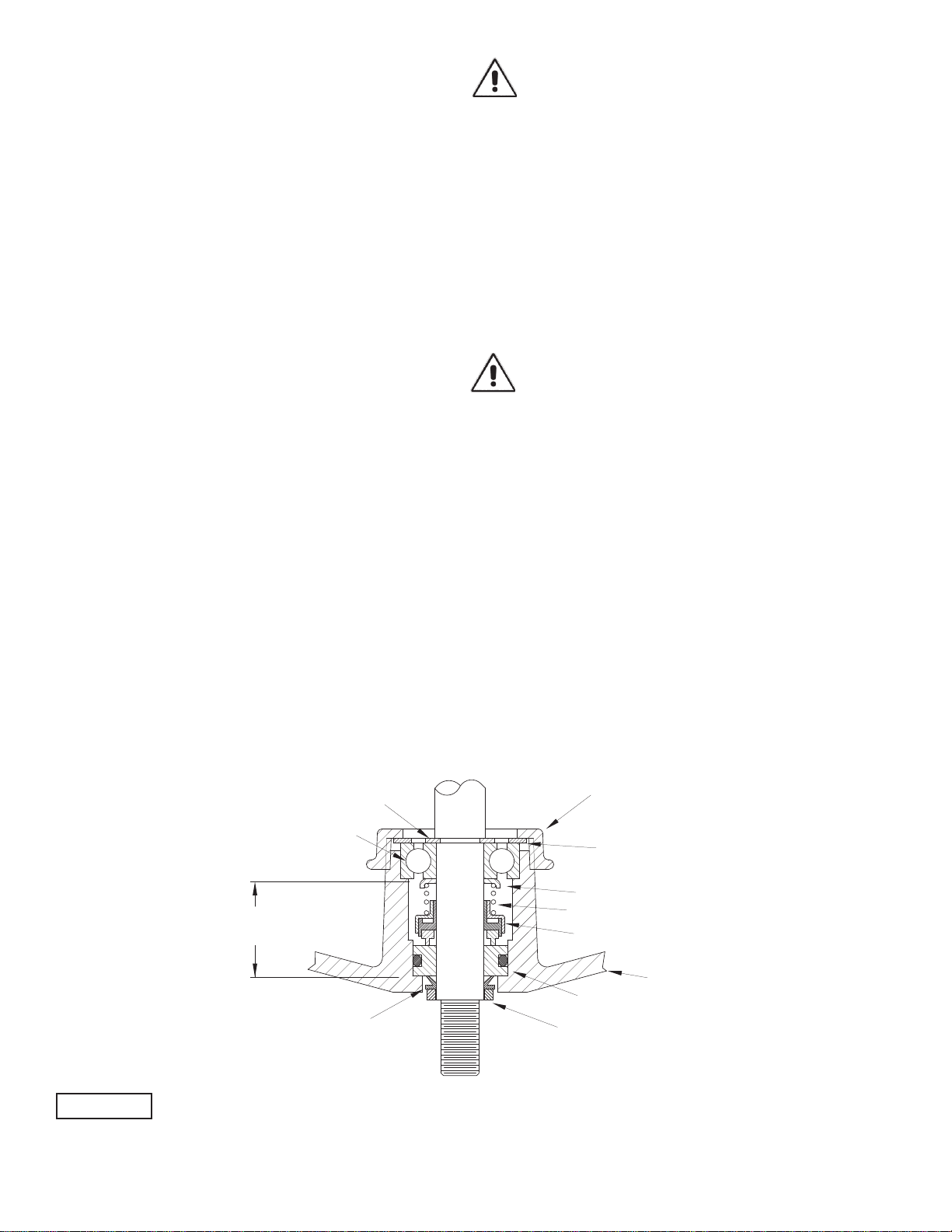
FIGURE 3
Seal Plate (25)
Spring (46c)
Retaining Ring (46d)
Rotating Member (46b)
Stationary (46a)
Seal Assembly (46)
PUMP END
(Outboard End)
MOTOR END
(Inboard End)
Exclusion Seal (17)
Pull Washer (16)
Washer (9)
Conduit Bushing (14)
Loading ...
Loading ...
Loading ...