Loading ...
Loading ...
Loading ...
Manufacturer of Quality Air Conditioning and Heating Products • www.islandaire.com • sales@islandaire.com • (800)-886-2759
40
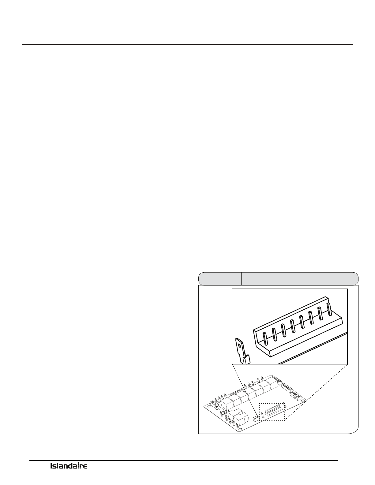
e remote thermostat interface terminal block is located on the power module board. A Wiring harness is provided with
conductors for all applications (Heat Cool, Heat Pump, Multispeed Fan, etc.). It provides a connection for remote thermo-
stat and energy management inputs.
To convert to thermostat operation:
1. Shut main power to unit o.
2. Access main control board and turn remote thermostat dip switch on.
3. Plug in the supplied thermostat harness.
4. Connect wires to eld-supplied thermostat.
Remote Thermostat Interface
Terminal R (Red)
Low voltage terminal to supply voltage to an external
wall mounted thermostat. is terminal is capable of
supplying 100 mA at 18-30 Vac RMS over the entire
input voltage range specied.
Terminal LS (Purple)
When this low voltage terminal is connected to the R
terminal, the compressor and electric heater are disabled
to provide an energy management system interface.
Terminal GH (Green)
When this low voltage terminal is connected to the R
terminal, and the unit is in remote mode, the blower/fan
will be requested for operation on high speed.
Terminal B (Blue)
When this low voltage terminal is connected to the R
terminal, and the unit is in the remote mode, the revers-
ing valve is energized. Hydronic and electric heat shall
be attempted as backups if the B terminal is asserted and
the compressor is locked out or disabled. is is subject
to the congured heat modes available.
Terminal Y (Yellow)
When this low voltage terminal is connected to the R
terminal, and the unit is in remote mode, the compressor
will be switched on (the GL or GH terminal must also be
connected to the R terminal).
Terminal W (White)
When this low-voltage terminal is connected to the R ter-
minal and the unit is in the remote mode, rst hydronic
heat is attempted and electric heat is switched on as
backup (the GL or GH terminal must also be connected
to the R terminal). is is subject to the congured heat
modes available.
Terminal GL (Orange)
When this low voltage terminal is connected to the R
terminal, and the unit is in remote mode, the blower/ fan
will be requested for operation on low speed.
Terminal C (Black)
Low voltage terminal, 24 Vac common, to provide oppo-
site polarity voltage to wall thermostat.
C
R
LS
GH
B
GL
Y
W
Thermostat Terminal Block Figure 44
Loading ...
Loading ...
Loading ...