Loading ...
Loading ...
Loading ...
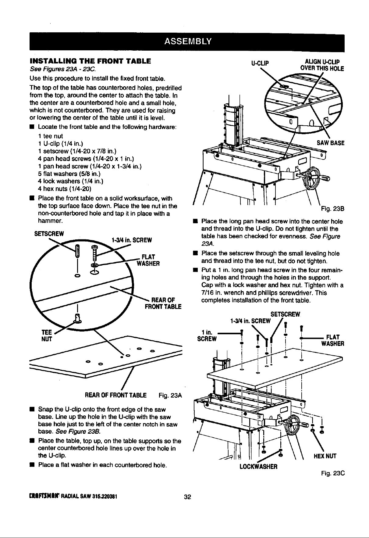
INSTALLING THE FRONTTABLE
See Figures 23A - 23C.
Use this procedure to installthe fixed fronttable.
The top ofthe table has counterbored holes, predrilled
from the top, around the center to attach the table. In
the center are a counterbored hole and a small hole,
which isnot counterbored.They are used for raising
or lowering the center ofthe table until itis level.
• Locate thefronttable and the followinghardware:
1 tee nut
1 U-clip (1/4 in.)
1 setscrew (1/4-20 x 7/8 in.)
4 pan head screws (1/4-20 x 1 in.)
1 pan head screw (1/4-20 x 1-3/4 in.)
5 flat washers (5/8 in.)
4 lock washers (1/4 in.)
4 hex nuts(1/4-20)
• Place thefronttable on a solidworksurface,with
the top surface face down. Race thetee nut inthe
non-counterboredhole and tap it in place witha
hammer.
U-CLIP AUGNU-CUP
OVERTHISHOLE
SAWBASE
Fig. 23B
• Place the long pan head screw intothe center hole
and thread intothe U-clip. Do nottighten untilthe
SETSCREW table has been checked for evenness. See Figure
_ SCREW 23A.
f_l _'_._,_ FLAT • Place thesetscrewthroughthe small levelinghole
r I _ WASHER and thread intothe tee nut, butdo not tighten.
ol ___ _k • Puta 1 in. long pan head screwin the four remain-
ingholesand throughthe holes inthe support.
Cap with a lock washer and hex nut.Tightenwith a
7/16 in.wrench and phillipsscrewdriver. This
REAROF completes installationofthe fronttable.
1-3/4in.SCREW/|
SCREW L !'I / ELAT
] _' T' ' WASHER
- i
REAROFFRONTTABLE Fig. 23A
• Snap the U-clip ontothe frontedge of the saw
base. Line up the hole inthe U-clip withthe saw
base holejustto the left ofthe center notchin saw
base. See Figure23B.
• Place thetable, top up, on the table supportssothe
center counterboredhole linesup over the hole in
the U-clip.
• Place a flat washer in each counterborsdhole.
LOCKWASHER
HEXNUT
Fig. 23C
[|lll_NlUr RADIALSAW315.220381 32
Loading ...
Loading ...
Loading ...