Gasoline containing up to 10% ethanol (E 10) is accept=
able for use inthis machine, The use of any gasoline e×=
ceeding l O%ethanol (E l O) willvoid the productwarranty,
Vous pouvez utiliser de I'essence contenant jusqu'a
10 % d'ethanol (El0) avec cet appareil. L'utilisation
d'essence contenant plus de 10 % d'ethanol annulera
la garantie du produit.
584 26 12-32 Rev. 2
Owner's Manual
Manuel du Proprietaire
917.250092
Please read the owner's manual carefully and make sure
you understand the instructions before using the machine.
Lisez tres attentivement et soyez certain de comprende
ces instructions avant d'utiliser cette machine. English/French
SAFETY RULES
SAFE OPERATION PRACTICES FOR WALK=BEHIND POWERED ROTARY TILLERS
TRAiNiNG
* Read the Owner's Manual carefully. Be thoroughly
familiar with the controls and the proper use of the
equipment. Know how to stop the unit and disengage
the controls quickly.
* Never allow children to operate the equipment. Never
allow adults to operate the equipment without proper
instruction.
Keep the area of operation clear of all persons, par-
ticularly small children, and pets.
PREPARATION
* Thoroughly inspect the area where the equipment is
to be used and remove all foreign objects.
* Disengage all clutches and shift into neutral before
starting the engine (motor).
* Do not operate the equipment without wearing ad-
equate outer garments. Wear footwear that will improve
footing on slippery surfaces.
* Handle fuel with care; it is highly flammable.
* Use an approved fuel container.
* Never add fuel to a running engine or hot engine.
* Fill fuel tank outdoors with extreme care. Never fill fuel
tank indoors.
* Replace gasoline cap securely and clean up spilled
fuel before restarting.
* Use extension cords and receptacles as specified by
the manufacturer for all units with electric drive motors
or electric starting motors.
* Never attempt to make any adjustments while the
engine (motor) is running (except where specifically
recommended by manufacturer).
OPERATION
* Do not put hands or feet near or under rotating parts.
Exercise extreme caution when operating on or cross-
ing gravel drives, walks, or roads. Stay alert for hidden
hazards or traffic. Do not carry passengers.
. After striking aforeign object, stop the engine (motor),
remove the wire from the spark plug, thoroughly inspect
the tiller for any damage, and repair the damage before
restarting and operating the tiller.
* Exercise caution to avoid slipping or falling.
If the unit should start to vibrate abnormally, stop the
engine (motor) and check immediately for the cause.
Vibration is generally a warning of trouble.
. Stop the engine (motor) when leaving the operating
position.
* Take all possible precautions when leaving the machine
unattended. Disengage the tines, shift into neutral,
and stop the engine.
. Before cleaning, repairing, or inspecting, shut off
the engine and make certain all moving parts have
stopped. Disconnectthe spark plug wire, and keep the
wire away from the plug to prevent accidental starting.
Disconnect the cord on electric motors.
* Do not run the engine indoors; exhaust fumes are
dangerous.
• Never operate the tiller without proper guards, plates,
or other safety protective devices in place.
• Keep children and pets away.
Do not overload the machine capacity by attempting
to till too deep at too fast a rate.
• Never operate the machine at high speeds on slippery
surfaces. Look behind and use care when backing.
Never allow bystanders near the unit.
Use only attachments and accessories approved by
the manufacturer of the tiller.
Never operate the tiller without good visibility or light.
Be careful when tilling in hard ground. The tines may
catch in the ground and propel the tiller forward. Ifthis
occurs, let go of the handlebars and do not restrain
the machine.
MAINTENANCE AND STORAGE
Keep machine, attachments, and accessories in safe
working condition.
Check shear pins, engine mounting bolts, and other
bolts at frequent intervals for proper tightness to be
sure the equipment is in safe working condition.
Never store the machine with fuel inthe fuel tank inside
a building where ignition sources are present, such
as hot water and space heaters, clothes dryers, and
the like. Allow the engine to cool before storing in any
enclosure.
Always refer to the operator's guide instructions for
important details if the tiller is to be stored for an ex-
tended period.
= IMPORTANT =
CAUTIONS, IMPORTANTS, AND NOTES ARE A MEANS OF
ATTRACTING ATTENTION TO IMPORTANT OR CRITICAL
INFORMATIONIN THIS MANUAL.
IMPORTANT: USED TO ALERT YOU THAT THERE IS A
POSSIBILITYOF DAMAGINGTHIS EQUIPMENT.
NOTE: Gives essential information that will aid you to
better understand, incorporate, or execute a particular
set of instructions.
Look for this symbol to point out im-
portant safety precautions. It means
CAUTION!!! BECOME ALERT!!! YOUR
SAFETY IS INVOLVED.
CAUTION: Always disconnect spark
plug wire and place wire where it can=
not contact spark plug in order to pre-
vent accidental starting when setting
up, transporting, adjusting or making
repairs.
WARNING
The engine exhaust from this product contains
chemicals known to the State of California to
cause cancer, birth defects, or other reproduc=
tive harm.
2
PRODUCT SPECIFICATIONS
Gasoline Capacity: 2.9 Quarts (2.7L)
Unleaded Regular
Oil (API:SG-SL): SAE 30 (Above 32°F/0°O)
(Capacity: 20 oz./0.6L) SAE 5W30 (Below 32°F/0°C)
Spark Plug: Champion RC12YC
(Gap: .030"/0.76mm)
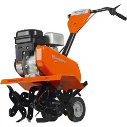
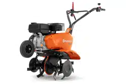
CONGRATULATIONS on your purchase of a new tiller. It
has been designed, engineered and manufactured to give
you the best possible dependability and performance.
Should you experience any problems you cannot easily
remedy, please contact your nearest authorized service
center. We have competent, well-trained technicians and
the proper tools to service or repair this unit.
Please read and retain this manual. The instructions will
enable you to assemble and maintain your tiller properly.
Always observe the "SAFETY RULES".
CUSTOMER RESPONSIBILITIES
• Read and observe the safety rules.
• Follow a regular schedule in maintaining, caring for
and using your tiller.
• Follow instructions under"Maintenance" and "Storage"
sections of this Manual.
IMPORTANT: THIS UNIT IS EQUIPPED WITH AN INTERNAL
COMBUSTION ENGINE AND SHOULD NOT BE USED ON
OR NEAR ANY UNIMPROVED FOREST-COVERED, BRUSH-
COVERED OR GRASS COVERED LAND UNLESSTHE ENGINE'S
EXHAUST SYSTEM IS EQUIPPED WITH A SPARK ARRESTER
MEETING APPLICABLE LOCAL LAWS (IF ANY). IF A SPARK
ARRESTER IS USED, ITSHOULD BE MAINTAINED IN EFFECTIVE
WORKING ORDER BY THE OPERATOR.
IN THE STATE OF CALIFORNIA, A SPARK ARRESTER IS
REQUIRED BY LAW (SECTION 4442 OF THE CALIFORNIA
PUBLIC RESOURCES CODE). OTHER STATES MAY HAVE
SIMILAR LAWS. FEDERAL LAWS APPLY ON FEDERAL LANDS.
SEE YOUR AUTHORIZED SERVICE CENTER/DEPARTMENT
FOR SPARK ARRESTER.
TABLE OF CONTENTS
SAFETY RULES ........................................................... 2
CUSTOMER RESPONSIBILITIES ............................... 3
PRODUCT SPECIFICATIONS ..................................... 3
ASSEMBLY ................................................................ 4-5
OPERATION .............................................................. 6-9
MAINTENANCE SCHEDULE ..................................... 10
MAINTENANCE .................................................... 10-12
SERVICE & ADJUSTMENTS ................................ 13-15
STORAGE .................................................................. 16
TROUBLESHOOTING ................................................ 17
REPAIR PARTS ..................................................... 18=23
WAR RANTY ........................................................... 24=27
FRAN(_AIS ................................................................. 29
3
ASSEMBLY
Your new tiller has been assembled at the factory with exception of those parts left unassembled for shipping purposes.
To ensure safe and proper operation of your tiller all parts and hardware you assemble must be tightened securely. Use
the correct tools as necessary to insure proper tightness.
TOOLS REQUIRED FOR ASSEMBLY
A socket wrench set will make assembly easier. Standard
wrench sizes are listed.
(1) Utility knife
(1) Screwdriver
(1) Pair of pliers
(2) 1/2" wrenches
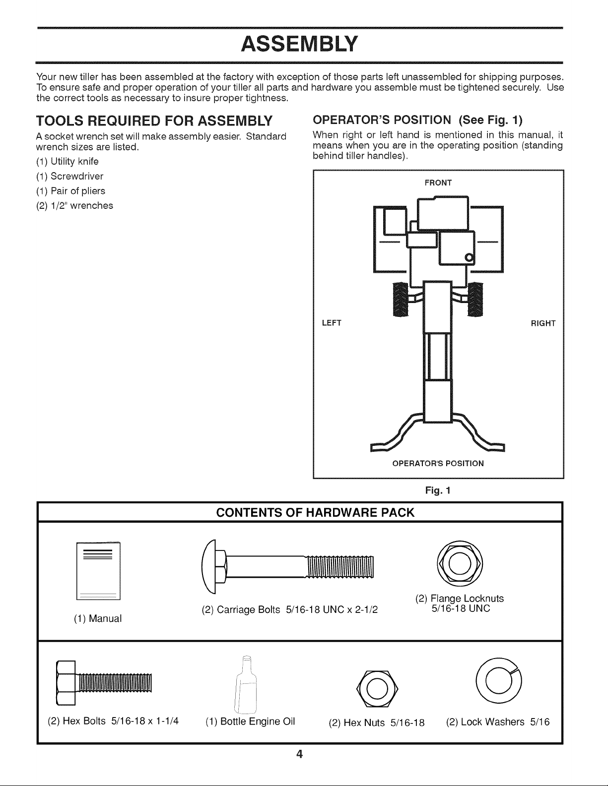
OPERATOR'S POSITION (See Fig. 1)
When right or left hand is mentioned in this manual, it
means when you are in the operating position (standing
behind tiller handles).
LEFT
FRONT
RIGHT
OPERATOR'S POSITION
Fig. 1
CONTENTS OF HARDWARE PACK
(1) Manual
(2) Carriage Bolts
5/16-18 UNC x 2-1/2
@
(2) Flange Locknuts
5/16-18 UNC
(2) Hex Bolts 5/16-18 x 1-1/4
/_ _h
(1) Bottle Engine Oil
@
(2) Hex Nuts 5/16-18
@
(2) Lock Washers 5/16
4
ASSEMBLY
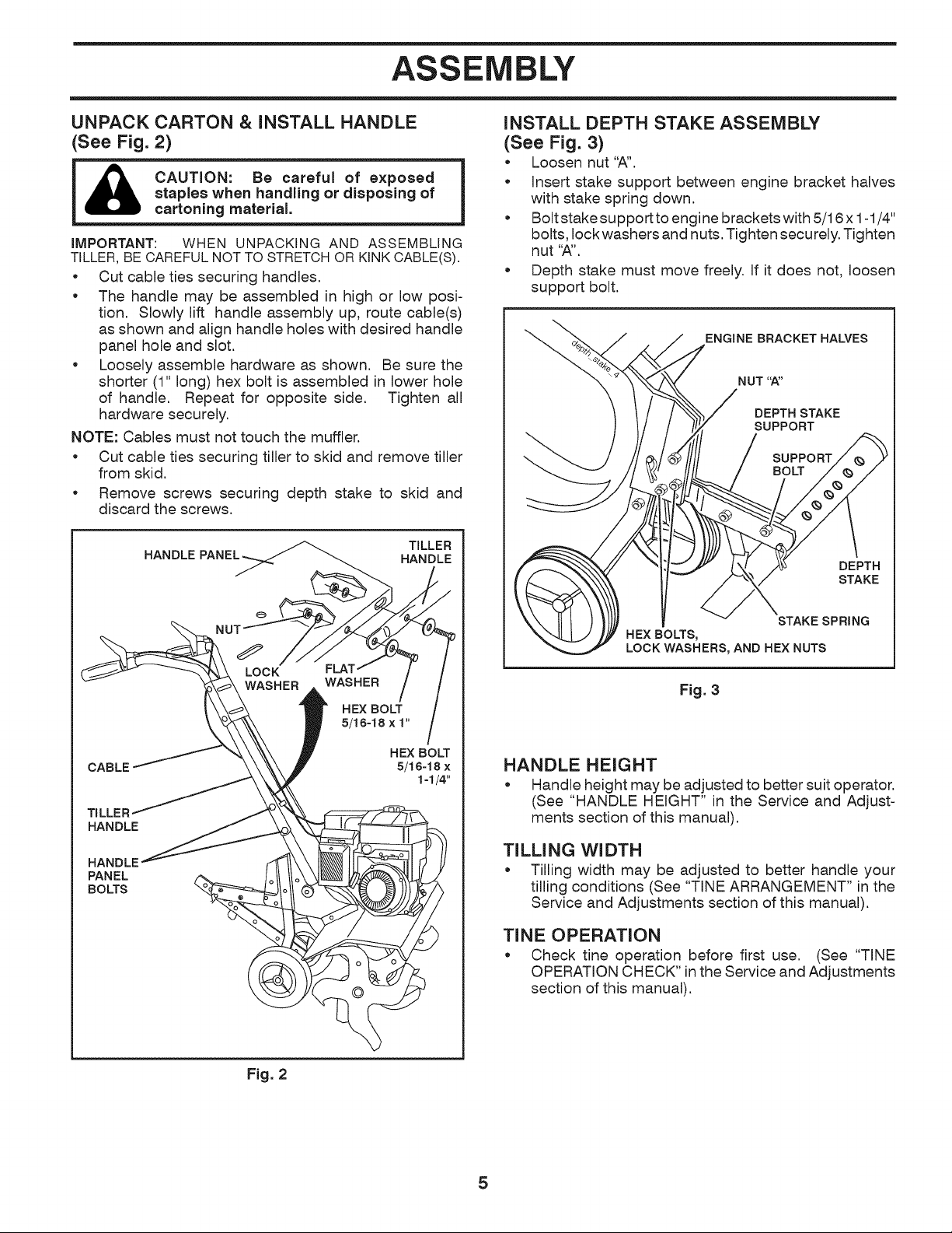
UNPACK CARTON & INSTALL HANDLE
(See Fig. 2)
_1 CAUTION: Be careful of exposed
staples when handling or disposing of
cartoning material.
IMPORTANT: WHEN UNPACKING AND ASSEMBLING
TILLER,BE CAREFUL NOT TO STRETCHOR KINK CABLE(S).
• Cut cable ties securing handles.
• The handle may be assembled in high or low posi-
tion. Slowly lift handle assembly up, route cable(s)
as shown and align handle holes with desired handle
panel hole and slot.
• Loosely assemble hardware as shown. Be sure the
shorter (1" long) hex bolt is assembled in lower hole
of handle. Repeat for opposite side. Tighten all
hardware securely.
NOTE: Cables must not touch the muffler.
• Cut cable ties securing tiller to skid and remove tiller
from skid.
• Remove screws securing depth stake to skid and
discard the screws.
HANDLE PANE_=_
TILLER
HANDLE
CABLE
HEX BOLT
5/16-18 x
i-i14"
HANDLE
HANDLE
PANEL
BOLTS
INSTALL DEPTH STAKE ASSEMBLY
(See Fig. 3)
• Loosen nut "A".
• Insert stake support between engine bracket halves
with stake spring down.
• Boltstakesupporttoenginebracketswith5/16x1-1/4"
bolts, lock washers and nuts. Tighten securely. Tighten
nut "A".
• Depth stake must move freely. If it does not, loosen
support bolt.
ENGINE BRACKET HALVES
NUT'W'
DEPTH STAKE
SUPPORT
SUPPORT
BOLT
DEPTH
STAKE
STAKE SPRING
HEX BOLTS,
LOCK WASHERS, AND HEX NUTS
Fig. 3
HANDLE HEIGHT
• Handle height may be adjusted to better suit operator.
(See "HANDLE HEIGHT" in the Service and Adjust-
ments section of this manual).
TILLING WIDTH
• Tilling width may be adjusted to better handle your
tilling conditions (See "TINE ARRANGEMENT" in the
Service and Adjustments section of this manual).
TINE OPERATION
• Check tine operation before first use. (See "TINE
OPERATION CHECK" in the Service and Adjustments
section of this manual).
Fig. 2
5
OPERATION
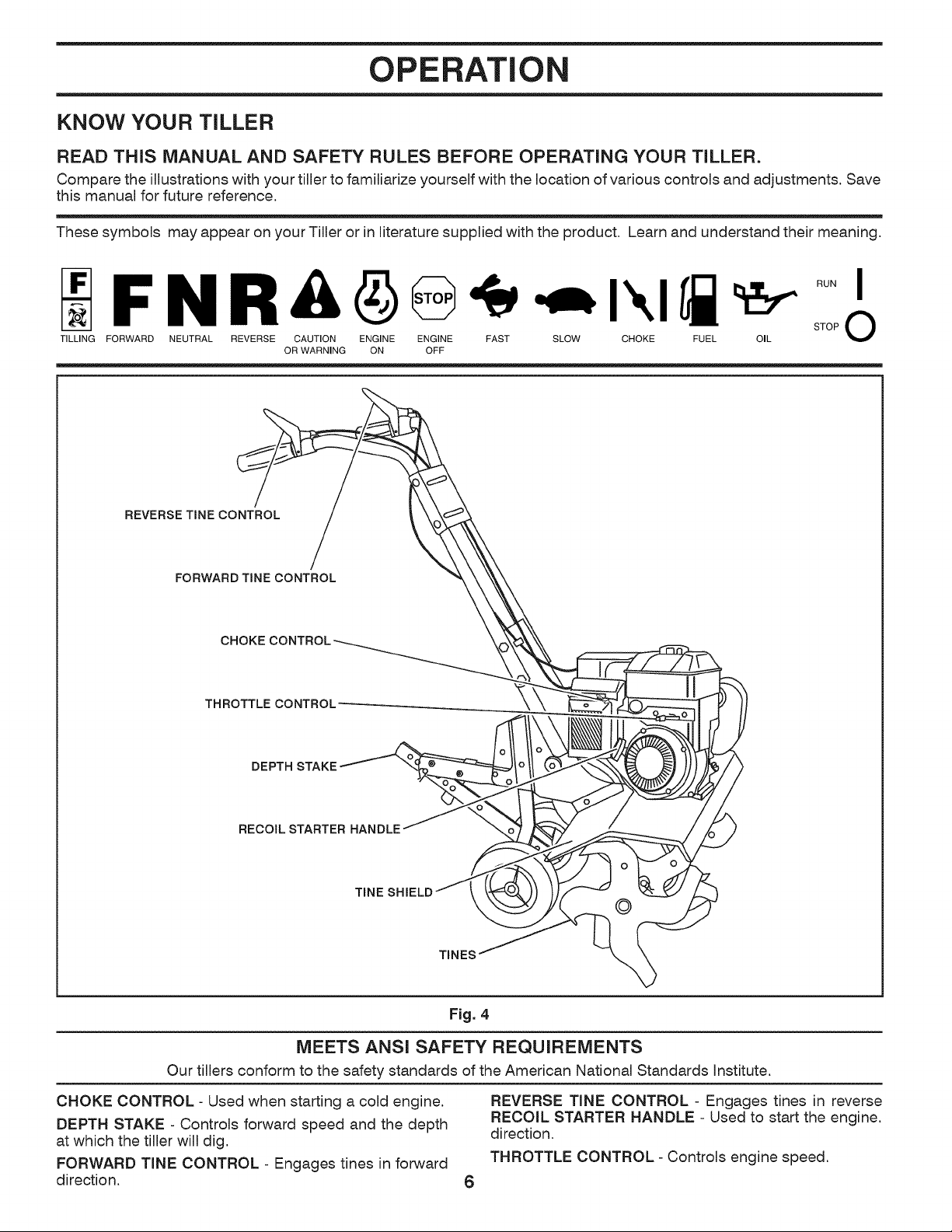
KNOW YOUR TILLER
READ THiS MANUAL AND SAFETY RULES BEFORE OPERATING YOUR TILLER.
Compare the illustrations with your tiller to familiarize yourself with the location of various controls and adjustments. Save
this manual for future reference.
These symbols may appear on your Tiller or in literature supplied with the product. Learn and understand their meaning.
TILLING FORWARD
N R & 6 _ IXI _J_ _ STopRUN _
NEUTRAL REVERSE CAUTION ENGINE ENGINE FAST SLOW CHOKE FUEL OIL
OR WARNING ON OFF
REVERSE TINE CONTROL
FORWARD TINE CONTROL
CHOKE
THROTTLE CONTROL .....
DEPTH STAKE
RECOIL STARTER HANDLE
©
TINES
Fig. 4
MEETS ANSI SAFETY REQUIREMENTS
Our tillers conform to the safety standards of the American National Standards Institute.
CHOKE CONTROL- Used when starting a cold engine.
DEPTH STAKE - Controls forward speed and the depth
at which the tiller will dig.
FORWARD TINE CONTROL - Engages tines in forward
direction.
6
REVERSE TINE CONTROL - Engages tines in reverse
RECOIL STARTER HANDLE - Used to start the engine.
direction.
THROTTLE CONTROL- Controls engine speed.
OPERATION
The operation of any tiller can result in foreign objects thrown into the eyes, which can result
in severe eye damage. Always wear safety glasses or eye shields before starting your tiller
and while tilling. We recommend a wide vision safety mask over spectacles or standard
safety glasses.
HOW TO USE YOUR TILLER
Know how to operate all controls before adding fuel and
oil or attempting to start engine.
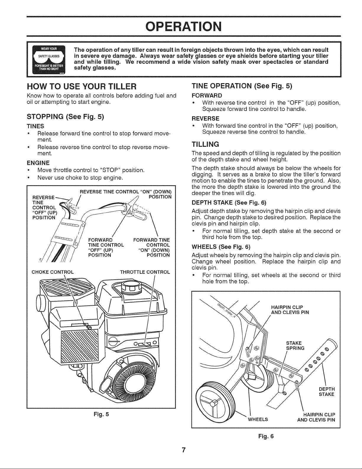
STOPPING (See Fig. 5)
TINES
* Release forward tine control to stop forward move-
ment.
* Release reverse tine control to stop reverse move-
ment.
ENGINE
* Move throttle control to "STOP" position.
* Never use choke to stop engine.
TINE
CONTROL
"OFF"(UP)
POSITION
REVERSE TINE CONTROL "ON" (DOWN)
POSITION
FORWARD FORWARD TINE
TINE CONTROL CONTROL
"OFF" (UP) "ON" (DOWN)
POSITION POSITION
CHOKECONTROL THROTTLE CONTROL
Fig. 5
TINE OPERATION (See Fig. 5)
FORWARD
* With reverse tine control in the "OFF" (up) position,
Squeeze forward tine control to handle.
REVERSE
* With forward tine control in the "OFF" (up) position,
Squeeze reverse tine control to handle.
TILLING
The speed and depth of tilling is regulated by the position
of the depth stake and wheel height.
The depth stake should always be below the wheels for
digging. It serves as a brake to slow the tiller's forward
motion to enable the tines to penetrate the ground. Also,
the more the depth stake is lowered into the ground the
deeper the tines will dig.
DEPTH STAKE (See Fig. 6)
Adjust depth stake by removing the hairpin clip and clevis
pin. Change depth stake to desired position. Replace the
clevis pin and hairpin clip.
* For normal tilling, set depth stake at the second or
third hole from the top.
WHEELS (See Fig. 6)
Adjust wheels by removing the hairpin clip and clevis pin.
Change wheel position. Replace the hairpin clip and
clevis pin.
For normal tilling, set wheels at the second or third
hole from the top.
HAIRPIN CLIP
AND CLEVIS PiN
STAKE
SPRING
DEPTH
STAKE
WHEELS
HAIRPIN CLIP
AND CLEVIS PiN
Fig. 6
7
OPERATION
TO TRANSPORT
CAUTION: Before lifting or transport=
ing, allow tiller engine and muffler to
cool. Disconnect sparkplug wire. Drain
gasoline from fuel tank.
AROUND THE YARD
* Tip depth stake forward until it is held by the stake
spring.
, Push tiller handles down, raising tines off the ground.
Push or pull tiller to desired location.
AROUND TOWN
, Disconnect spark plug wire.
, Drain fuel tank.
, Transport in upright position to prevent oil leakage.
BEFORE STARTING ENGINE
iMPORTANT: BE VERY CAREFULNOT TO ALLOW DiRT TO
ENTER THE ENGINE WHEN CHECKING OR ADDING OiL OR
FUEL. USECLEANOILAND FUELAND STORE iNAPPROVED,
CLEAN,COVEREDCONTAINERS. USECLEANFiLL FUNNELS.
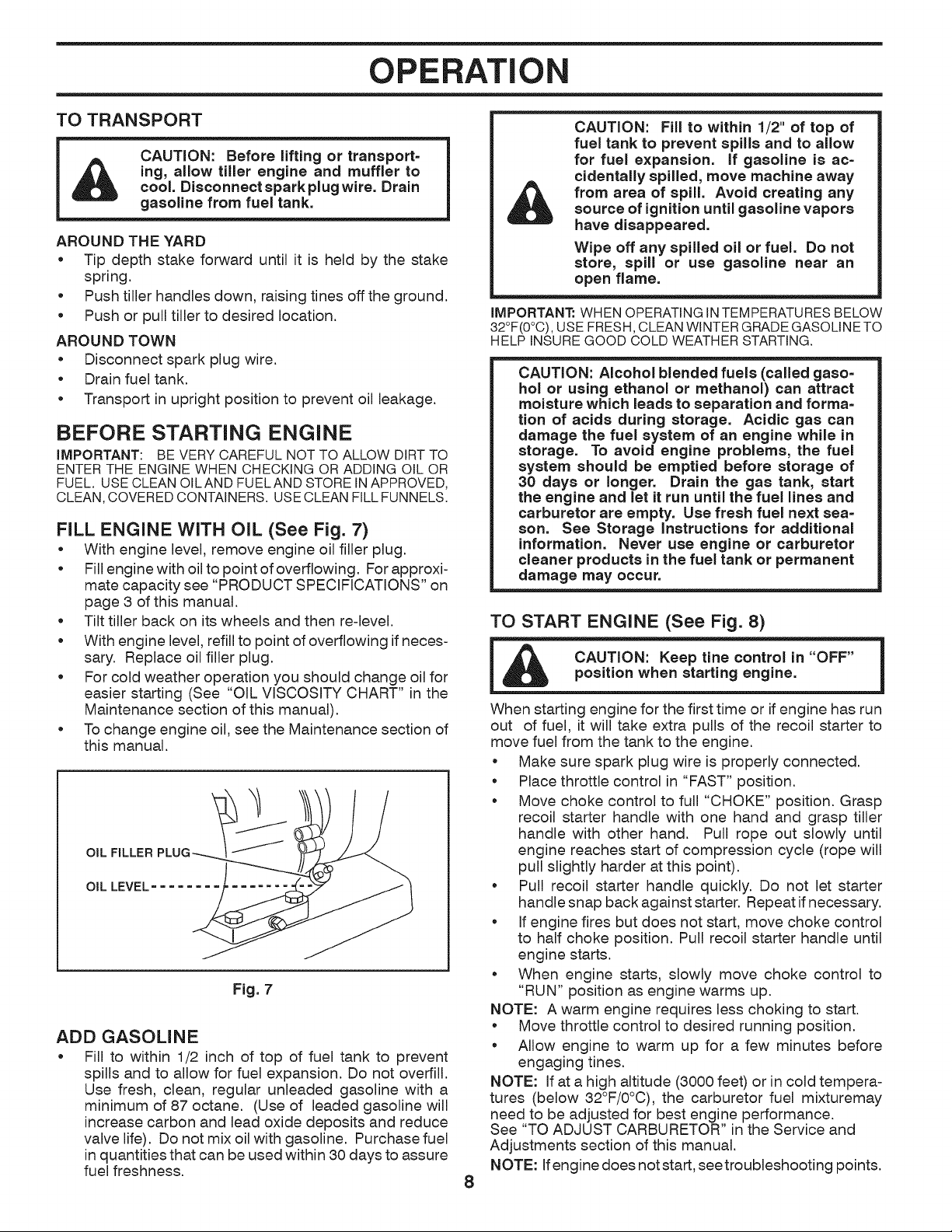
FILL ENGINE WITH OIL (See Fig. 7)
• With engine level, remove engine oil filler plug.
Fill engine with oil to point of overflowing. For approxi-
mate capacity see "PRODUCT SPECIFICATIONS" on
page 3 of this manual.
Tilt tiller back on its wheels and then re-level.
• With engine level, refill to point of overflowing if neces-
sary. Replace oil filler plug.
For cold weather operation you should change oil for
easier starting (See "OIL VISCOSITY CHART" in the
Maintenance section of this manual).
To change engine oil, see the Maintenance section of
this manual.
OIL FILLER
OIL LEVEL
Fig. 7
ADD GASOLINE
* Fill to within 1/2 inch of top of fuel tank to prevent
spills and to allow for fuel expansion. Do not overfill.
Use fresh, clean, regular unleaded gasoline with a
minimum of 87 octane. (Use of leaded gasoline will
increase carbon and lead oxide deposits and reduce
valve life). Do not mix oil with gasoline. Purchase fuel
in quantities that can be used within 30 days to assure
fuel freshness.
8
CAUTION: Fill to within 1/2" of top of
fuel tank to prevent spills and to allow
for fuel expansion, if gasoline is ac=
cidentally spilled, move machine away
from area of spill, Avoid creating any
source of ignition until gasoline vapors
have disappeared.
Wipe off any spilled oil or fuel. Do not
store, spill or use gasoline near an
open flame.
IMPORTANT: WHEN OPERATING iN TEMPERATURES BELOW
32°F(0°C), USE FRESH, CLEAN WINTER GRADE GASOLINE TO
HELP INSURE GOOD COLD WEATHER STARTING.
CAUTION: Alcohol blended fuels (called gaso=
hol or using ethanol or methanol) can attract
moisture which leads to separation and forma=
tion of acids during storage. Acidic gas can
damage the fuel system of an engine while in
storage. To avoid engine problems, the fuel
system should be emptied before storage of
30 days or longer. Drain the gas tank, start
the engine and let it run until the fuel lines and
carburetor are empty. Use fresh fuel next sea-
son. See Storage instructions for additional
information. Never use engine or carburetor
cleaner products in the fuel tank or permanent
damage may occur.
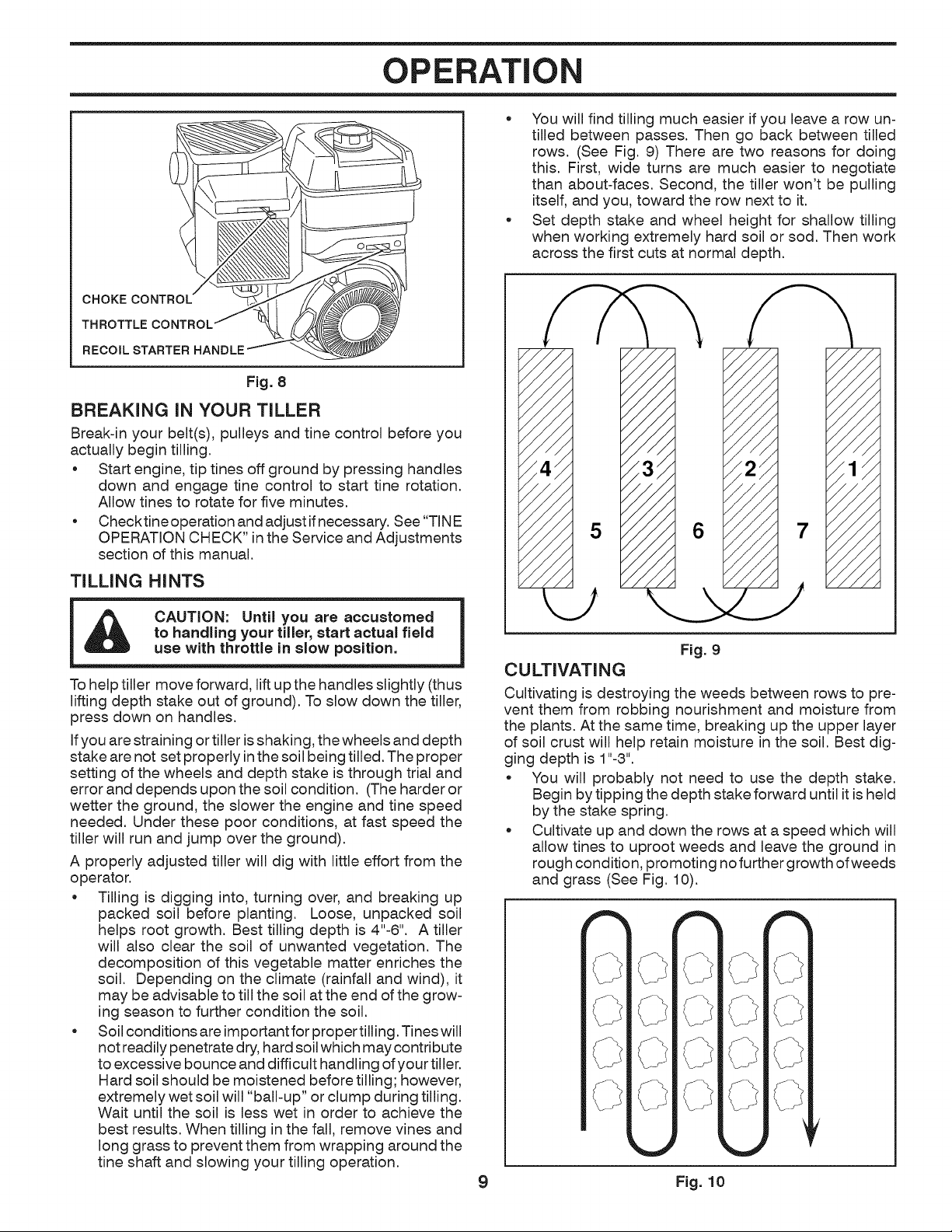
TO START ENGINE (See Fig. 8)
l CAUTION: Keep tine control in "OFF"
position when starting engine.
l
When starting engine for the first time or if engine has run
out of fuel, it will take extra pulls of the recoil starter to
move fuel from the tank to the engine.
• Make sure spark plug wire is properly connected.
Place throttle control in "FAST" position.
Move choke control to full "CHOKE" position. Grasp
recoil starter handle with one hand and grasp tiller
handle with other hand. Pull rope out slowly until
engine reaches start of compression cycle (rope will
pull slightly harder at this point).
Pull recoil starter handle quickly. Do not let starter
handle snap back against starter. Repeat if necessary.
If engine fires but does not start, move choke control
to half choke position. Pull recoil starter handle until
engine starts.
When engine starts, slowly move choke control to
"RUN" position as engine warms up.
NOTE: A warm engine requires less choking to start.
Move throttle control to desired running position.
Allow engine to warm up for a few minutes before
engaging tines.
NOTE: If at a high altitude (3000 feet) or in cold tempera-
tures (below 32°F/0°C), the carburetor fuel mixturemay
need to be adjusted for best engine performance.
See "TO ADJUST CARBURETOR" in the Service and
Adjustments section of this manual.
NOTE: If engine does not start, seetroubleshooting points.
OPERATION
CHOKE
RECOIL STARTER HANDLE
Fig. 8
BREAKING iN YOUR TILLER
Break-in your belt(s), pulleys and tine control before you
actually begin tilling.
• Start engine, tip tines off ground by pressing handles
down and engage tine control to start tine rotation.
Allow tines to rotate for five minutes.
• Checktine operation and adjust if necessary. See "TINE
OPERATION CHECK" in the Service and Adjustments
section of this manual.
TILLING HINTS
CAUTION: Until you are accustomed
to handling your tiller, start actual field
use with throttle in slow position.
To help tiller move forward, lift up the handles slightly (thus
lifting depth stake out of ground). To slow down the tiller,
press down on handles.
If you are straining or tiller is shaking, the wheels and depth
stake are not set properly in the soil being tilled. The proper
setting of the wheels and depth stake is through trial and
error and depends upon the soil condition. (The harder or
wetter the ground, the slower the engine and tine speed
needed. Under these poor conditions, at fast speed the
tiller will run and jump over the ground).
A properly adjusted tiller will dig with little effort from the
operator.
• Tilling is digging into, turning over, and breaking up
packed soil before planting. Loose, unpacked soil
helps root growth. Best tilling depth is 4"-6". A tiller
will also clear the soil of unwanted vegetation. The
decomposition of this vegetable matter enriches the
soil. Depending on the climate (rainfall and wind), it
may be advisable to till the soil at the end of the grow-
ing season to further condition the soil.
Soil conditions are important for proper tilling. Tines will
not readily penetrate dry, hard soil which may contribute
to excessive bounce and difficult handling of your tiller.
Hard soil should be moistened before tilling; however,
extremely wet soil will "ball-up" or clump during tilling.
Wait until the soil is less wet in order to achieve the
best results. When tilling in the fall, remove vines and
long grass to prevent them from wrapping around the
tine shaft and slowing your tilling operation.
You will find tilling much easier if you leave a row un-
tilled between passes. Then go back between tilled
rows. (See Fig. 9) There are two reasons for doing
this. First, wide turns are much easier to negotiate
than about-faces. Second, the tiller won't be pulling
itself, and you, toward the row next to it.
Set depth stake and wheel height for shallow tilling
when working extremely hard soil or sod. Then work
across the first cuts at normal depth.
Fig. 9
CULTIVATING
Cultivating is destroying the weeds between rows to pre-
vent them from robbing nourishment and moisture from
the plants. At the same time, breaking up the upper layer
of soil crust will help retain moisture in the soil. Best dig-
ging depth is 1"-3".
You will probably not need to use the depth stake.
Begin by tipping the depth stake forward until it is held
by the stake spring.
Cultivate up and down the rows at a speed which will
allow tines to uproot weeds and leave the ground in
rough condition, promoting no further growth of weeds
and grass (See Fig. 10).
_rd j
j\
t "-,
_71J
C
i \
4 %
__s _
,._1\
<,
9 Fig. 10
MAINTENANCE
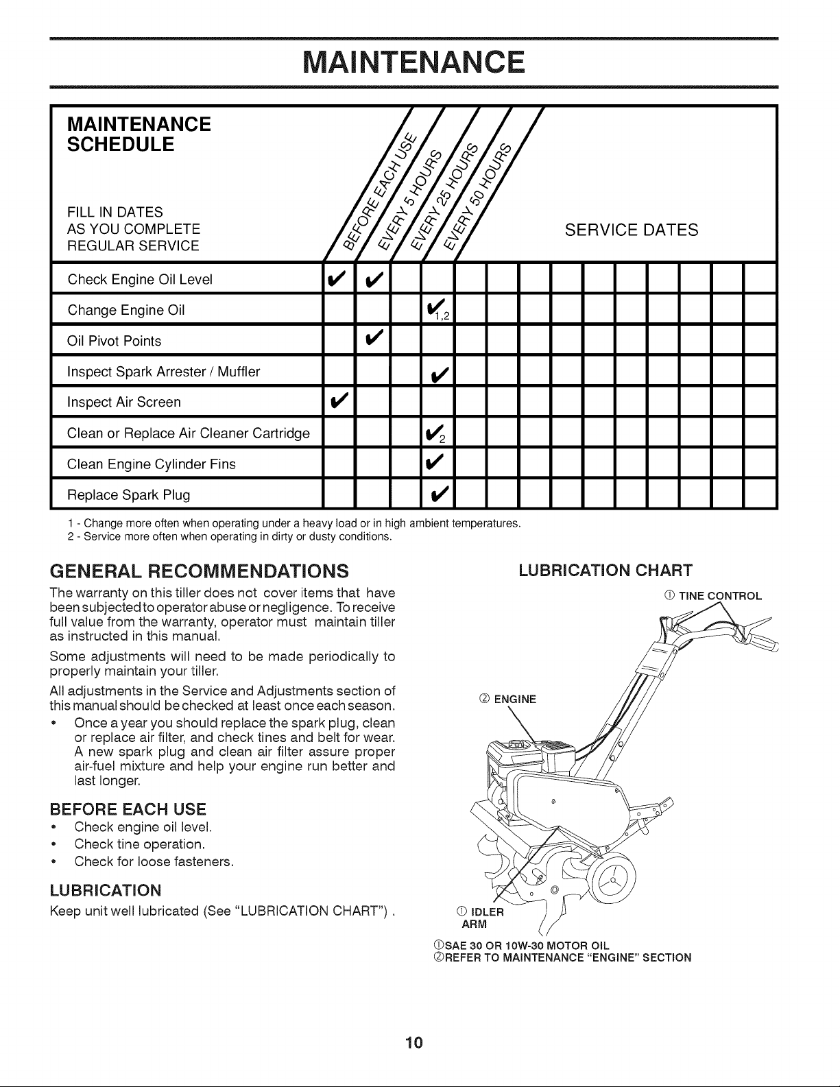
MAINTENANCE
SCHEDULE
FILL IN DATES
AS YOU COMPLETE
REGULAR SERVICE
Check Engine Oil Level
SERVICE DATES
Change Engine Oil _1,2
Oil Pivot Points !_
Inspect Spark Arrester / Muffler !_
Inspect Air Screen tf
Clean or Replace Air Cleaner Cartridge !_2
Clean Engine Cylinder Fins
Replace Spark Plug !1_
1 - Change more often when operating under a heavy load or in high ambient temperatures.
2 - Service more often when operating in dirty or dusty conditions.
GENERAL RECOMMENDATIONS
The warranty on this tiller does not cover items that have
been subjected to operator abuse or negligence. To receive
full value from the warranty, operator must maintain tiller
as instructed in this manual.
Some adjustments will need to be made periodically to
properly maintain your tiller.
All adjustments in the Service and Adjustments section of
this manual should be checked at least once each season.
• Once a year you should replace the spark plug, clean
or replace air filter, and check tines and belt for wear.
A new spark plug and clean air filter assure proper
air-fuel mixture and help your engine run better and
last longer.
BEFORE EACH USE
• Check engine oil level.
• Check tine operation.
• Check for loose fasteners.
LUBRICATION
Keep unit well lubricated (See "LUBRICATION CHART").
LUBRICATION CHART
Q ENGINE
(_) IDLER
ARM
TINE CONTROL
/
(DSAE 30 OR 10W-30 MOTOR OIL
QREFER TO MAINTENANCE "ENGINE" SECTION
10
MAINTENANCE
Disconnect spark plug wire before performing any maintenance (except carburetor adjustment) to
prevent accidental starting of engine.
Prevent fires! Keep the engine free of grass, leaves, spilled oil, or fuel. Remove fuel from tank
before tipping unit for maintenance. Clean muffler area of all grass, dirt, and debris.
Do not touch hot muffler or cylinder fins as contact may cause burns.
ENGINE
LUBRiCATiON
Use only high quality detergent oil rated with AP! service
classification SG-SL. Select the oil's SAE viscosity grade
according to your expected temperature.
oF
104
86
68
32
14
-4
-22
l_ __ m
o
w
0
Fig. 11
°O
40
30
20
lO
o
-10
-20
-30
NOTE: Although multi-viscosity oils (5W-30, 10W-30, etc.)
improve starting in cold weather, these multi-viscosity oils
will result in increased oil consumption when used above
32°F (0°C). Check your engine oil level more frequently
to avoid possible engine damage from running low on oil.
Change the oil after every 50 hours of operation or at least
once a year if the tiller is not used for 50 hours in one year.
Check the crankcase oil level before starting the engine
and after each five (5) hours of continuous use. Add SAE
30 motor oil or equivalent. Tighten oil filler plug securely
each time you check the oil level.
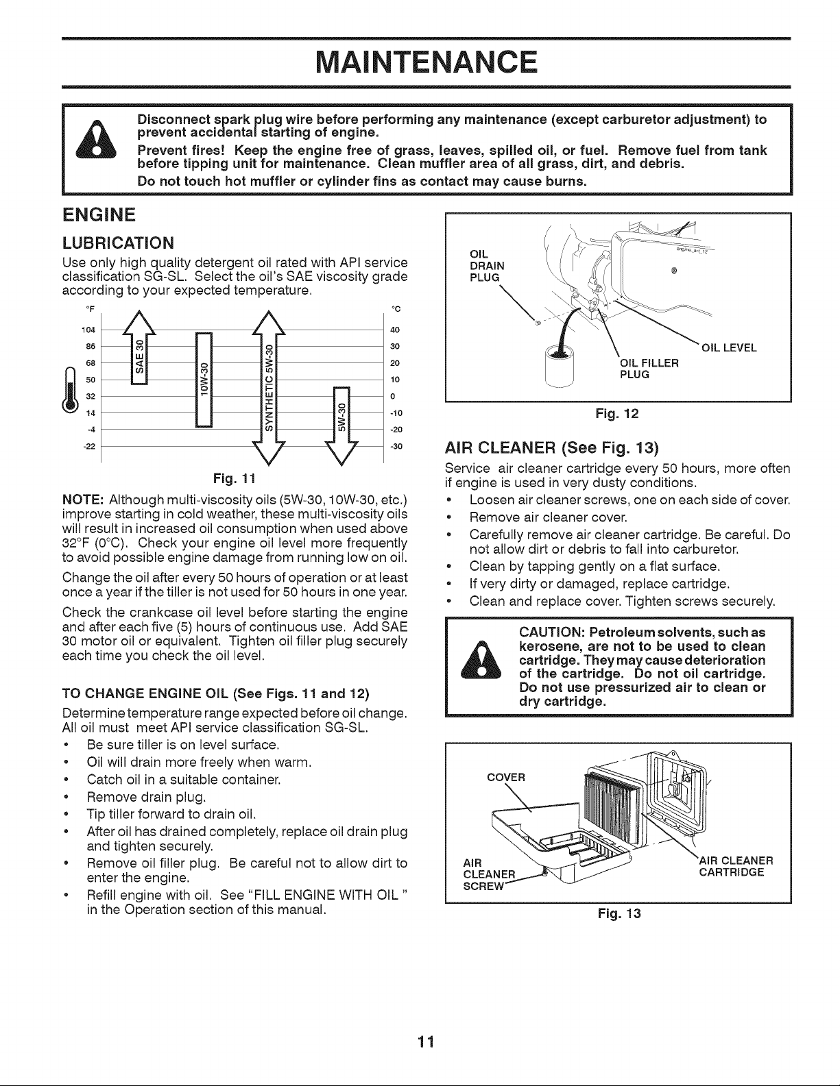
TO CHANGE ENGINE OIL (See Figs. 11 and 12)
Determine temperature range expected before oil change.
All oil must meet API service classification SG-SL.
• Be sure tiller is on level surface.
• Oil will drain more freely when warm.
• Catch oil in a suitable container.
• Remove drain plug.
• Tip tiller forward to drain oil.
• After oil has drained completely, replace oil drain plug
and tighten securely.
• Remove oil filler plug. Be careful not to allow dirt to
enter the engine.
• Refill engine with oil. See "FILL ENGINE WITH OIL "
in the Operation section of this manual.
OIL
DRAIN
PLUG
\
OiL FILLER
PLUG
OIL LEVEL
Fig. 12
AIR CLEANER (See Fig. 13)
Service air cleaner cartridge every 50 hours, more often
if engine is used in very dusty conditions.
• Loosen air cleaner screws, one on each side of cover.
• Remove air cleaner cover.
• Carefully remove air cleaner cartridge. Be careful. Do
not allow dirt or debris to fall into carburetor.
• Clean by tapping gently on a flat surface.
• If very dirty or damaged, replace cartridge.
• Clean and replace cover. Tighten screws securely.
&
CAUTION: Petroleum solvents, such as
kerosene, are not to be used to clean
cartridge. They may cause deterioration
of the cartridge. Do not oil cartridge.
Do not use pressurized air to clean or
dry cartridge.
COVER_ _=R
AIR CLEANER
CARTR,OGE
Fig. 13
11
MAINTENANCE
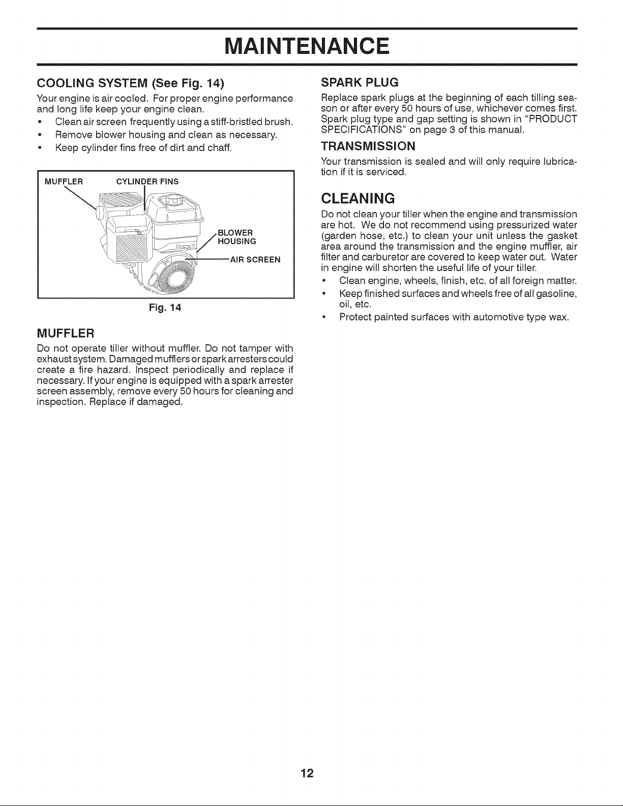
COOLING SYSTEM (See Fig. 14)
Your engine is air cooled. For proper engine performance
and long life keep your engine clean.
o Clean air screen frequently using a stiff-bristled brush.
o Remove blower housing and clean as necessary.
• Keep cylinder fins free of dirt and chaff.
MUFFLER CYLINDER FINS
MUFFLER
Do not operate tiller without muffler. Do not tamper with
exhaust system. Damaged mufflers or spark arresters could
create a fire hazard. Inspect periodically and replace if
necessary. If your engine is equipped with a spark arrester
screen assembly, remove every 50 hours for cleaning and
inspection. Replace if damaged.
SPARK PLUG
Replace spark plugs at the beginning of each tilling sea-
son or after every 50 hours of use, whichever comes first.
Spark plug type and gap setting is shown in "PRODUCT
SPECIFICATIONS" on page 3 of this manual.
TRANSMISSION
Your transmission is sealed and will only require lubrica-
tion if it is serviced.
CLEANING
Do not clean your tiller when the engine and transmission
are hot. We do not recommend using pressurized water
(garden hose, etc.) to clean your unit unless the gasket
area around the transmission and the engine muffler, air
filter and carburetor are covered to keep water out. Water
in engine will shorten the useful life of your tiller.
Clean engine, wheels, finish, etc. of all foreign matter.
• Keep finished surfaces and wheels free of all gasoline,
oil, etc.
Protect painted surfaces with automotive type wax.
12
SERVICE AND ADJUSTMENTS
CAUTION: Disconnect spark plug wire from spark plug and place wire where it cannot come into
contact with plug.
TILLER
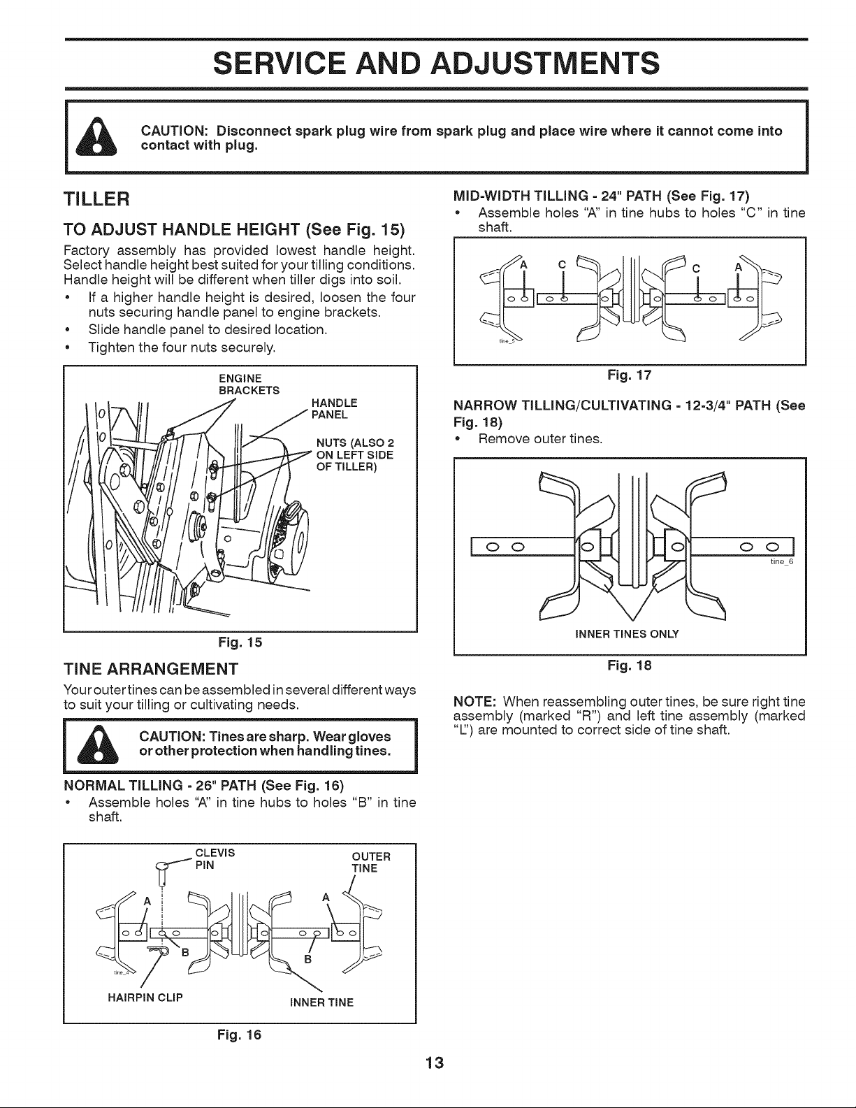
TO ADJUST HANDLE HEIGHT (See Fig. 15)
Factory assembly has provided lowest handle height.
Select handle height best suited for your tilling conditions.
Handle height will be different when tiller digs into soil.
• If a higher handle height is desired, loosen the four
nuts securing handle panel to engine brackets.
Slide handle panel to desired location.
Tighten the four nuts securely.
ENGINE
BRACKETS
HANDLE
/I PANEL
NUTS (ALSO 2
ON LEFT SIDE
OF TILLER)
Fig. 15
TINE ARRANGEMENT
Your outer tines can be assembled in several different ways
to suit your tilling or cultivating needs.
CAUTION: Tines are sharp. Wear gloves
or other protection when handling tines.
NORMAL TILLING =26" PATH (See Fig. 16)
* Assemble holes "A" in tine hubs to holes "B" in tine
shaft.
MID=WIDTH TILLING - 24" PATH (See Fig. 17)
* Assemble holes "A" in tine hubs to holes "C" in tine
shaft.
A C C A
[o_ 6o]
Fig. 17
NARROW TILLING/CULTIVATING - 12-3/4" PATH (See
Fig. 18)
* Remove outer tines.
OII I IO
INNER TINES ONLY
ool
tine 6
Fig. 18
NOTE: When reassembling outer tines, be sure right tine
assembly (marked "R") and left tine assembly (marked
"Z') are mounted to correct side of tine shaft.
CLEVIS OUTER
i_'_ PIN TINE
....
HAIRPIN CLIP INNER TINE
Fig. 16
13
SERVICE AND ADJUSTMENTS
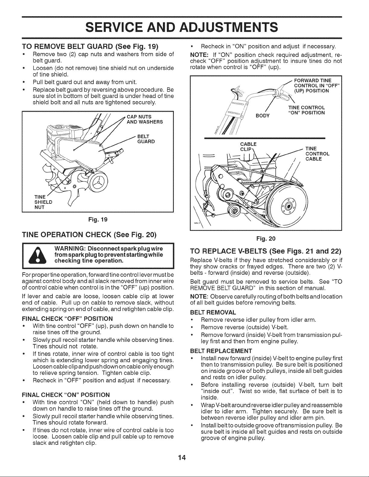
TO REMOVE BELT GUARD (See Fig. 19)
* Remove two (2) cap nuts and washers from side of
belt guard.
. Loosen (do not remove) tine shield nut on underside
of tine shield.
e
e
Pull belt guard out and away from unit.
Replace belt guard by reversing above procedure. Be
sure slot in bottom of belt guard is under head of tine
shield bolt and all nuts are tightened securely.
TINE
SHIELD
NUT
•CAP NUTS
AND WASHERS
GUARD
Fig. 19
TINE OPERATION CHECK (See Fig. 20)
WARNING: Disconnect spark plug wire
from spark plug to prevent starting while
checking tine operation.
For proper tine operation, forward tine control lever must be
against control body and all slack removed from inner wire
of control cable when control is in the "OFF" (up) position.
If lever and cable are loose, loosen cable clip at lower
end of cable. Pull up on cable to remove slack, without
extending spring on end of cable, and retighten cable clip.
FINAL CHECK "OFF" POSITION
• With tine control "OFF" (up), push down on handle to
raise tines off the ground.
• Slowly pull recoil starter handle while observing tines.
Tines should not rotate.
• If tines rotate, inner wire of control cable is too tight
which is extending lower spring and engaging tines.
Loosen cable clip and push down on cable only enough
to relieve spring tension. Tighten cable clip.
• Recheck in "OFF" position and adjust if necessary.
FINAL CHECK "ON" POSITION
• With tine control "ON" (held down to handle) push
down on handle to raise tines off the ground.
• Slowly pull recoil starter handle while observing tines.
Tines should rotate forward.
* If tines do not rotate, inner wire of control cable is too
loose. Loosen cable clip and pull cable up to remove
slack and retighten clip.
Recheck in "ON" position and adjust if necessary.
NOTE: If "ON" position check required adjustment, re-
check "OFF" position adjustment to insure tines do not
rotate when control is "OFF" (up).
FORWARD TINE
CONTROL IN "OFF"
.... (UP) POSITION
BODY
TINECONTROL
"ON'POSITION
CABLE
CLiP TINE
CONTROL
CABLE
Fig. 20
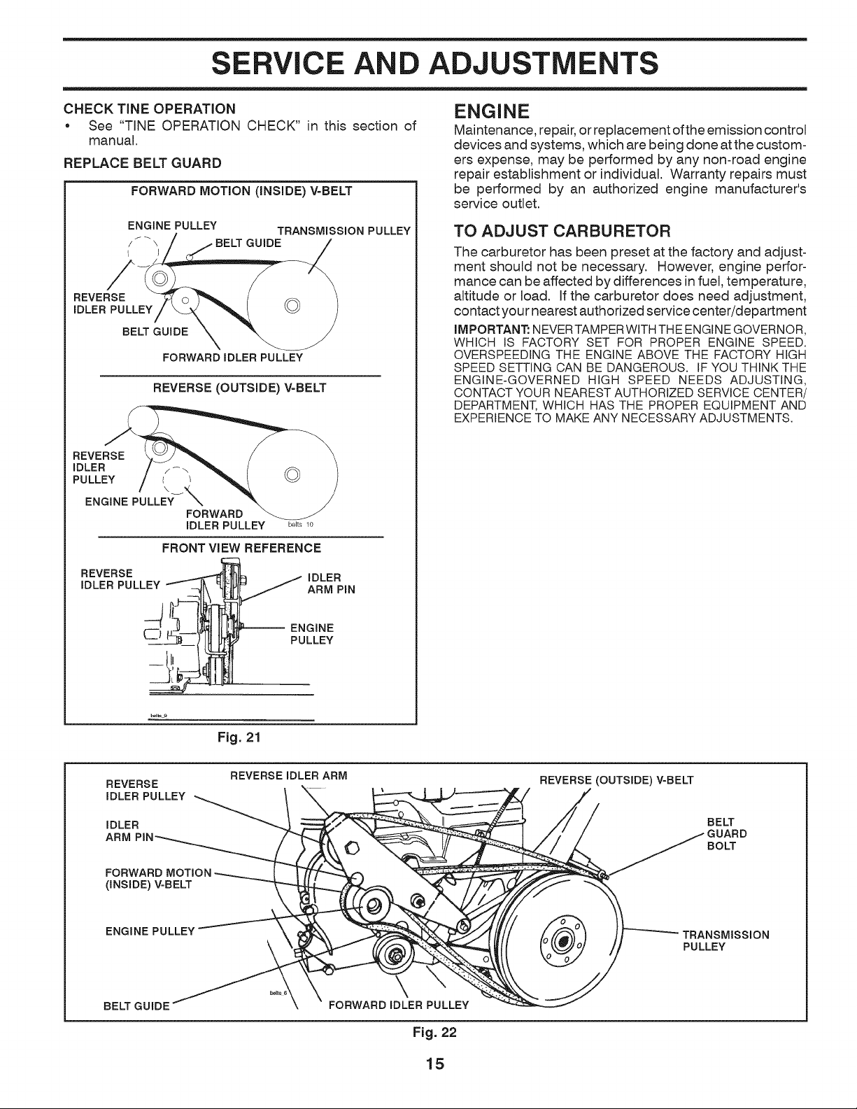
TO REPLACE V=BELTS (See Figs. 21 and 22)
Replace V-belts if they have stretched considerably or if
they show cracks or frayed edges. There are two (2) V-
belts- forward (inside) and reverse (outside).
Belt guard must be removed to service belts. See "TO
REMOVE BELT GUARD" in this section of manual.
NOTE: Observe carefully routing of both belts and location
of all belt guides before removing belts.
BELT REMOVAL
• Remove reverse idler pulley from idler arm.
• Remove reverse (outside) V-belt.
• Remove forward (inside) V-belt from transmission pul-
ley first and then from engine pulley.
BELT REPLACEMENT
* Install new forward (inside) V-belt to engine pulley first
then to transmission pulley. Be sure belt is positioned
on inside groove of both pulleys, inside all belt guides
and rests on idler pulley.
* Before installing reverse (outside) V-belt, turn belt
"inside out". Twist so wide, flat surface of belt is to
inside.
• WrapV-beltaround reverse idler pulleyand reassemble
idler to idler arm. Tighten securely. Be sure belt is
between reverse idler pulley and idler arm pin.
• Install beltto outside groove oftransmission pulley. Be
sure belt is inside all belt guides and rests on outside
groove of engine pulley.
14
SERVICE AND ADJUSTMENTS
CHECK TINE OPERATION
• See "TINE OPERATION CHECK" in this section of
manual.
REPLACE BELT GUARD
FORWARD MOTION (iNSiDE) V-BELT
ENGINE PULLEY TRANSMISSION PULLEY
/ I _ \ BELT GUIDE
REVERSE
IDLER PULLEY
BELT GUIDE
FORWARD IDLER PULLEY
REVERSE (OUTSIDE) V-BELT
REVERSE
iDLER
PULLEY I /
\
ENGINE PULLEY-_X
FORWARD
IDLER PULLEY
belts 10
FRONT VIEW REFERENCE
REVERSE _ IDLER
ENGINE
Maintenance, repair, or replacement ofthe emission control
devices and systems, which are being done atthe custom-
ers expense, may be performed by any non-road engine
repair establishment or individual. Warranty repairs must
be performed by an authorized engine manufacturer's
service outlet.
TO ADJUST CARBURETOR
The carburetor has been preset at the factory and adjust-
ment should not be necessary. However, engine perfor-
mance can be affected by differences in fuel, temperature,
altitude or load. if the carburetor does need adjustment,
contact your nearest authorized service center/department
IMPORTANT: NEVER TAMPER WITH THE ENGINE GOVERNOR,
WHICH IS FACTORY SET FOR PROPER ENGINE SPEED.
OVERSPEEDING THE ENGINE ABOVE THE FACTORY HIGH
SPEED SETTING CAN BE DANGEROUS. IF YOU THINK THE
ENGINE-GOVERNED HIGH SPEED NEEDS ADJUSTING,
CONTACT YOUR NEAREST AUTHORIZED SERVICE CENTER/
DEPARTMENT, WHICH HAS THE PROPER EQUIPMENT AND
EXPERIENCE TO MAKE ANY NECESSARY ADJUSTMENTS.
Fig. 21
REVERSE
IDLER PULLEY
IDLER
ARM
REVERSEIDLER ARM
REVERSE (OUTSIDE) V-BELT
BEg
GUARD
BOLT
(INSIDE) V-BELT
ENGINE PULLEY
TRANSMISSION
PULLEY
BELT GUIDE FORWARD IDLER PULLEY
Fig. 22
15
STORAGE
Immediately prepare your tiller for storage atthe end of the
season or if the unit will not be used for 30 days or more.
WARNING: Never store the tiller with
gasoline in the tank inside a building
where fumes may reach an open flame
or spark. Allow the engine to cool before
storing in any enclosure.
TILLER
• Clean entire tiller (See "CLEANING" in the Maintenance
section of this manual).
• Inspect and replace belts, if necessary (See belt re-
placement instructions in the Service and Adjustments
section of this manual).
• Lubricate as shown in the Maintenance section of this
manual.
• Be sure that all nuts, bolts and screws are securely
fastened. Inspect moving parts for damage, breakage
and wear. Replace if necessary.
• Touch up all rusted or chipped paint surfaces; sand
lightly before painting.
ENGINE
FUEL SYSTEM
IMPORTANT: IT IS IMPORTANTTO PREVENTGUMDEPOSITS
FROM FORMINGIN ESSENTIALFUEL SYSTEMPARTSSUCH
AS THE CARBURETOR,FUEL FILTER,FUEL HOSE, OR TANK
DURING STORAGE. ALSO, EXPERIENCE INDICATES THAT
ALCOHOL BLENDED FUELS (CALLEDGASOHOL OR USING
ETHANOLOR METHANOL)CANATTRACTMOISTUREWHICH
LEADSTO SEPARATIONAND FORMATIONOF ACIDS DURING
STORAGE.ACIDIC GAS CAN DAMAGETHE FUELSYSTEMOF
AN ENGINE WHILE IN STORAGE.
• Drain the fuel tank.
• Start the engine and let it run until the fuel lines and
carburetor are empty.
• Never use engine or carburetor cleaner products in
the fuel tank or permanent damage may occur.
NOTE: Fuel stablizer is an acceptable alternative in
minimizing the formation of fuel gum deposits during
storage. Add stabilizer to gasoline in fuel tank or storage
container. Always follow the mix ratio found on stablizer
container. Run engine at least 10 minutes after adding
stablizer to allow the stabilizer to reach the carburetor.
Do not drain the gas tank and carburetor if using fuel
stabilizer.
ENGINE OIL
Drain oil (with engine warm) and replace with clean oil.
(See "ENGI NE" in the Maintenance section of this manual).
CYLINDER(S)
• Remove spark plug.
• Pour 1 ounce (29 ml) of oil through spark plug hole
into cylinder.
• Pull starter handle slowly several times to distribute
oil.
• Replace with new spark plug.
OTHER
• Do not store gasoline from one season to another.
• Replace your gasoline can if your can starts to rust.
Rust and/or dirt in your gasoline will cause problems.
• If possible, store your unit indoors and cover it to give
protection from dust and dirt.
• Cover your unit with a suitable protective cover that
does not retain moisture. Do not use plastic. Plastic
cannot breathe which allows condensation to form
and will cause your unit to rust.
IMPORTANT: NEVER COVER TILLER WHILE ENGINE AND
EXHAUSTAREASARE STILL WARM.
16

TROUBLESHOOTING POINTS
PROBLEM CAUSE CORRECTION
Will not start
Hard to start
Loss of power
Engine overheats
Excessive bounce/
difficult handling
Soil bails up or clumps
Engine runs but tiller
won't move
Engine runs but labors
when tilling
1. Out of fuel.
2. Engine not "CHOKED" properly.
3. Engine flooded.
4. Dirty air cleaner.
5. Water in fuel.
6. Clogged fuel tank.
7. Loose spark plug wire.
8. Bad spark plug or improper gap.
9. Carburetor out of adjustment.
1. Throttle control not set properly.
2. Dirty air cleaner.
3. Bad spark plug or improper gap.
4. Stale or dirty fuel.
5. Loose spark plug wire.
6. Carburetor out of adjustment.
1. Engine is overloaded.
2. Dirty air cleaner.
3. Low oil level/dirty oil.
4. Faulty spark plug.
5. Oil in fuel.
6. Stale or dirty fuel.
7. Water in fuel.
8. Clogged fuel tank.
9. Spark plug wire loose.
10. Dirty engine air screen.
11. Dirty/clogged muffler.
12. Carburetor out of adjustment.
13. Poor compression.
1. Low oil level/dirty oil.
2. Dirty engine air screen.
3. Dirty engine.
4. Partially plugged muffler.
5. Improper carburetor adjustment.
1. Ground too dry and hard.
2. Wheels and depth stake incorrectly adjusted.
1. Ground too wet.
1. Tine control is not engaged.
2. V-belt not correctly adjusted.
3. V-belt is off pulley(s).
1. Tilling too deep.
2. Throttle control not properly adjusted.
3. Carburetor out of adjustment.
1. Fill fuel tank.
2. See "TO START ENGINE" in the Operation section.
3. Wait several minutes before attempting to start.
4. Clean or replace air cleaner cartridge.
5. Drain fuel tank and carburetor, and refill tank with fresh
gasoline.
6. Remove fuel tank and clean.
7. Make sure spark plug wire is seated properly on plug.
8. Replace spark plug or adjust gap.
9. Make necessary adjustments.
1. Place throttle control in "FAST" position.
2. Clean or replace air cleaner cartridge.
3. Replace spark plug or adjust gap.
4. Drain fuel tank and refill with fresh gasoline.
5. Make sure spark plug wire is seated properly on plug.
6. Make necessary adjustments.
1. Set depth stake and wheels for shallower tilling.
2. Clean or replace air cleaner cartridge.
3. Check oil level/change oil.
4. Clean and regap or change spark plug.
5. Drain and clean fuel tank and refill, and clean carburetor.
6. Drain fuel tank and refill with fresh gasoline.
7. Drain fuel tank and carburetor, and refill tank with fresh
gasoline.
8. Remove fuel tank and clean.
9. Connect and tighten spark plug wire.
10. Clean engine air screen.
11. Clean/replace muffler.
12. Make necessary adjustments.
13. Contact an authorized service center/department.
1. Check oil level/change oil.
2. Clean engine air screen.
3. Clean cylinder fins, air screen, muffler area.
4. Remove and clean muffler.
5. Adjust carburetor to richer position.
1. Moisten ground or wait for more favorable soil
conditions.
2. Adjust wheels and depth stake.
1. Wait for more favorable soil conditions.
1. Engage tine control.
2. Inspect/adjust V-belt.
3. Inspect V-belt.
1. Set depth stake for shallower tilling.
2. Check throttle control setting.
3. Make necessary adjustments.
17
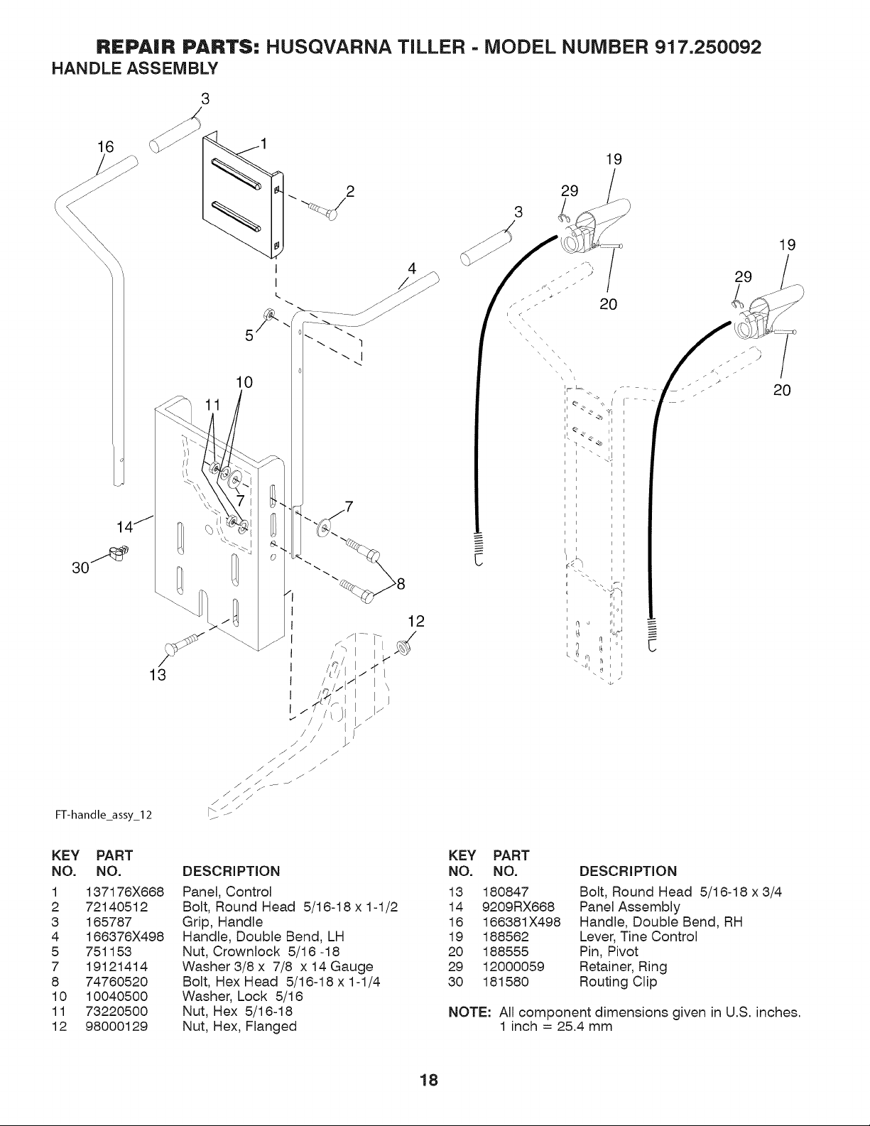
REPAIR PARTS: HUSQVARNA TILLER - MODEL NUMBER 917.250092
HANDLE ASSEMBLY
3
16
30"
FT-handle_assy_l 2
13
2 29
3 /
10
12
19
C
I, _, E:
i i
r_ i
_\11\ _ : i
-4.
19
20
KEY PART
NO. NO.
1 137176X668
2 72140512
3 165787
4 166376X498
5 751153
7 19121414
8 74760520
10 10040500
11 73220500
12 98000129
DESCRIPTION
Panel, Control
Bolt, Round Head 5/16-18 x 1-1/2
Grip, Handle
Handle, Double Bend, LH
Nut, Crownlock 5/16 -18
Washer 3/8 x 7/8 x 14 Gauge
Bolt, Hex Head 5/16-18 x 1-1/4
Washer, Lock 5/16
Nut, Hex 5/16-18
Nut, Hex, Flanged
KEY PART
NO. NO. DESCRIPTION
13 180847 Bolt, Round Head 5/16-18 x3/4
14 9209RX668 Panel Assembly
16 166381X498 Handle, Double Bend, RH
19 188562 Lever, Tine Control
20 188555 Pin, Pivot
29 12000059 Retainer, Ring
30 181580 Routing Clip
NOTE: All component dimensions given in U.S. inches.
1 inch = 25.4 mm
18
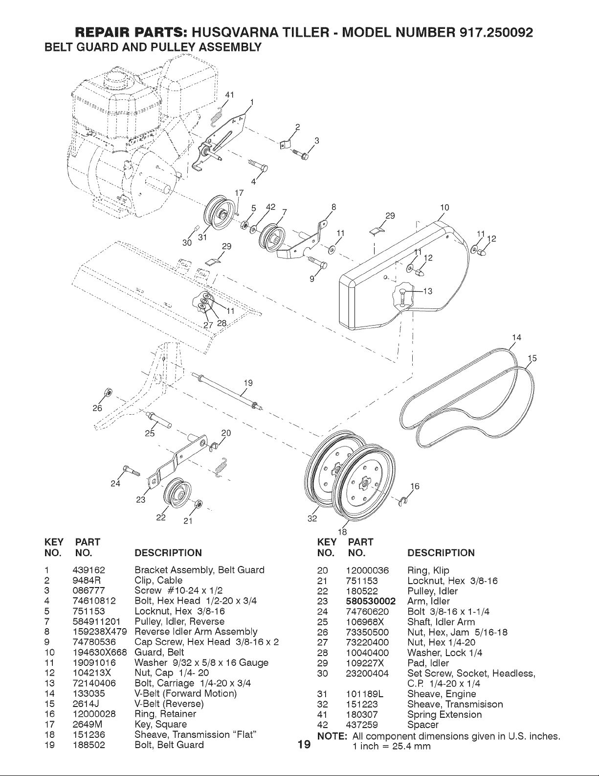
REPAIR PARTS: HUSQVARNA TILLER - MODEL NUMBER 917.250092
/%
24
23
/
22 21
KEY PART
NO. NO. DESCRIPTION
12
_J
14
/
32
16
18
KEY PART
NO. NO. DESCRIPTION
1 439162
2 9484R
3 086777
4 74610812
5 751153
7 584911201
8 159238X479
9 74780536
10 194630X668
11 19091016
12 104213X
13 72140406
14 133035
15 2614J
16 12000028
17 2649M
18 151236
19 188502
Bracket Assembly, Belt Guard
Clip, Cable
Screw #10-24 x 1/2
Bolt, Hex Head 1/2-20 x 3/4
Locknut, Hex 3/8-16
Pulley, Idler, Reverse
Reverse Idler Arm Assembly
Cap Screw, Hex Head 3/8-16 x 2
Guard, Belt
Washer 9/32 x 5/8 x 16 Gauge
Nut, Cap 1/4- 20
Bolt, Carriage 1/4-20 x 3/4
V-Belt (Forward Motion)
V-Belt (Reverse)
Ring, Retainer
Key, Square
Sheave, Transmission "Flat"
Bolt, Belt Guard
19
20 12000036 Ring, Klip
21 751153 Locknut, Hex 3/8-16
22 180522 Pulley, Idler
23 580530002 Arm, Idler
24 74760620 Bolt 3/8-16 x 1-1/4
25 106968X Shaft, Idler Arm
26 73350500 Nut, Hex, Jam 5/16-18
27 73220400 Nut, Hex 1/4-20
28 10040400 Washer, Lock 1/4
29 109227X Pad, Idler
30 23200404 Set Screw, Socket, Headless,
C.R 1/4-20x 1/4
31 101189L Sheave, Engine
32 151223 Sheave, Transmisison
41 180307 Spring Extension
42 437259 Spacer
NOTE: All component dimensions given in U.S. inches.
1 inch = 25.4 mm
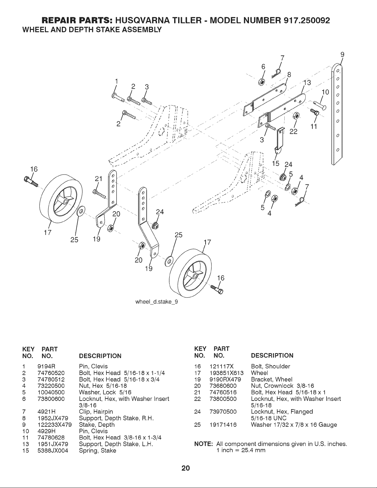
REPAIR PARTS: HUSQVARNA TILLER - MODEL NUMBER 917.250092
WHEEL AND DEPTH STAKE ASSEMBLY
16
25
1
7
24
25
17
wheel d.stake 9
KEY PART
NO. NO.
1 9194R
2 74760520
3 74780512
4 73220500
5 10040500
6 73800600
7 4921H
8 1952JX479
9 122233X479
10 4929H
11 74780628
13 1951JX479
15 5388JX004
DESCRIPTION
Pin, Clevis
Bolt, Hex Head 5/16-18 x 1-1/4
Bolt, Hex Head 5/16-18 x 3/4
Nut, Hex 5/16-18
Washer, Lock 5/16
Locknut, Hex, with Washer Insert
3/8-16
Clip, Hairpin
Support, Depth Stake, R.H.
Stake, Depth
Pin, Clevis
Bolt, Hex Head 3/8-16 x 1-3/4
Support, Depth Stake, L.H.
Spring, Stake
KEY PART
NO. NO. DESCRIPTION
16 121117X
17 193851X613
19 9190RX479
20 73680600
21 74760516
22 73800500
24 73970500
25 19171416
Bolt, Shoulder
Wheel
Bracket, Wheel
Nut, Crownlock 3/8-16
Bolt, Hex Head 5/16-18 x 1
Locknut, Hex, with Washer Insert
5/16-18
Locknut, Hex, Flanged
5/16-18 UNC
Washer 17/32 x 7/8 x 16 Gauge
NOTE: All component dimensions given in U.S. inches.
1 inch = 25.4 mm
20
REPAIR PARTS: HUSQVARNA TILLER - MODEL NUMBER 917.250092
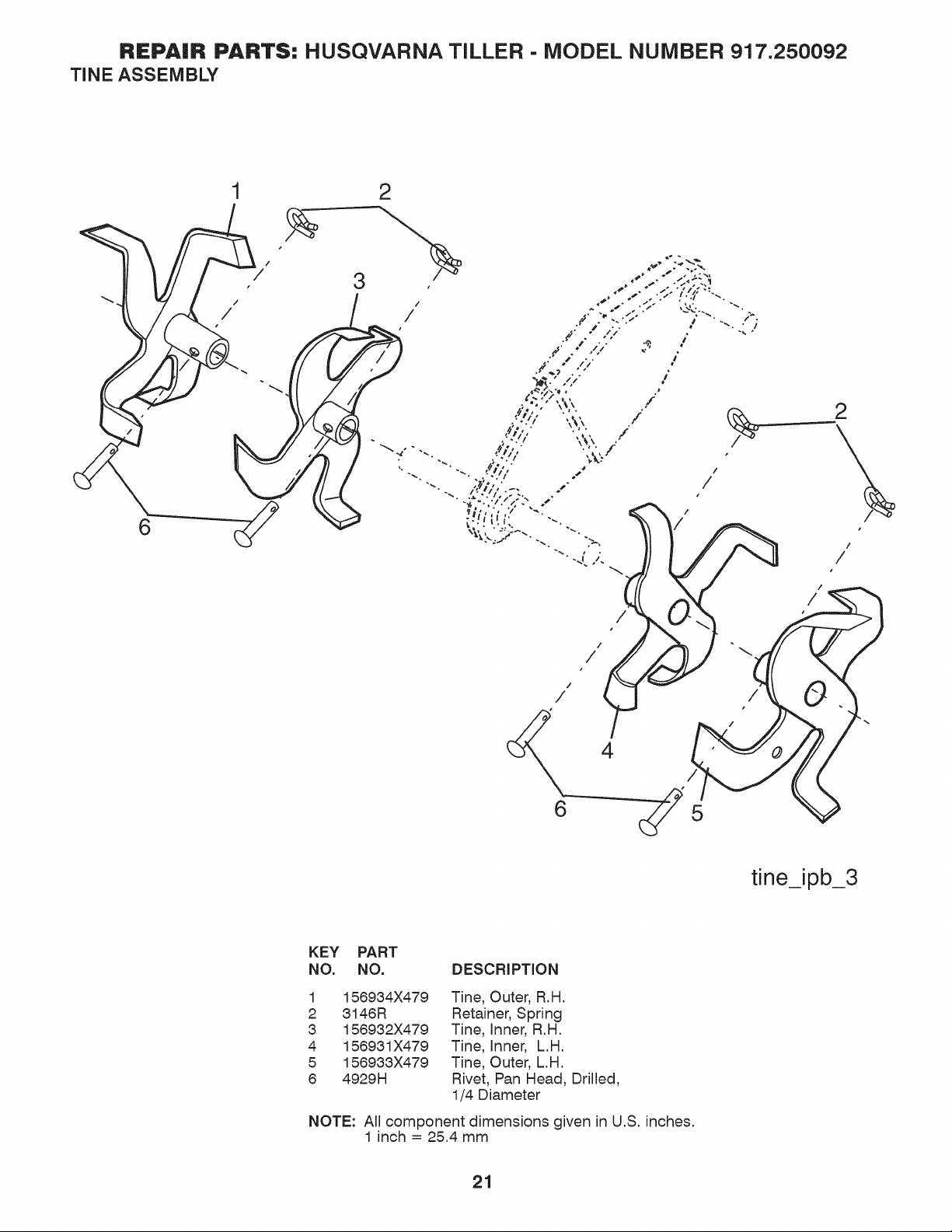
TINE ASSEMBLY
2
5
/
/
/
tine_ipb_3
KEY PART
NO. NO. DESCRIPTION
1
2
3
4
5
6
156934X479
3146R
156932X479
156931X479
156933X479
4929H
Tine, Outer, R.H.
Retainer, Spring
Tine, Inner, R.H.
Tine, Inner, L.H.
Tine, Outer, L.H.
Rivet, Pan Head, Drilled,
1/4 Diameter
NOTE: All component dimensions given in U.S. inches•
1 inch = 25.4 mm
21
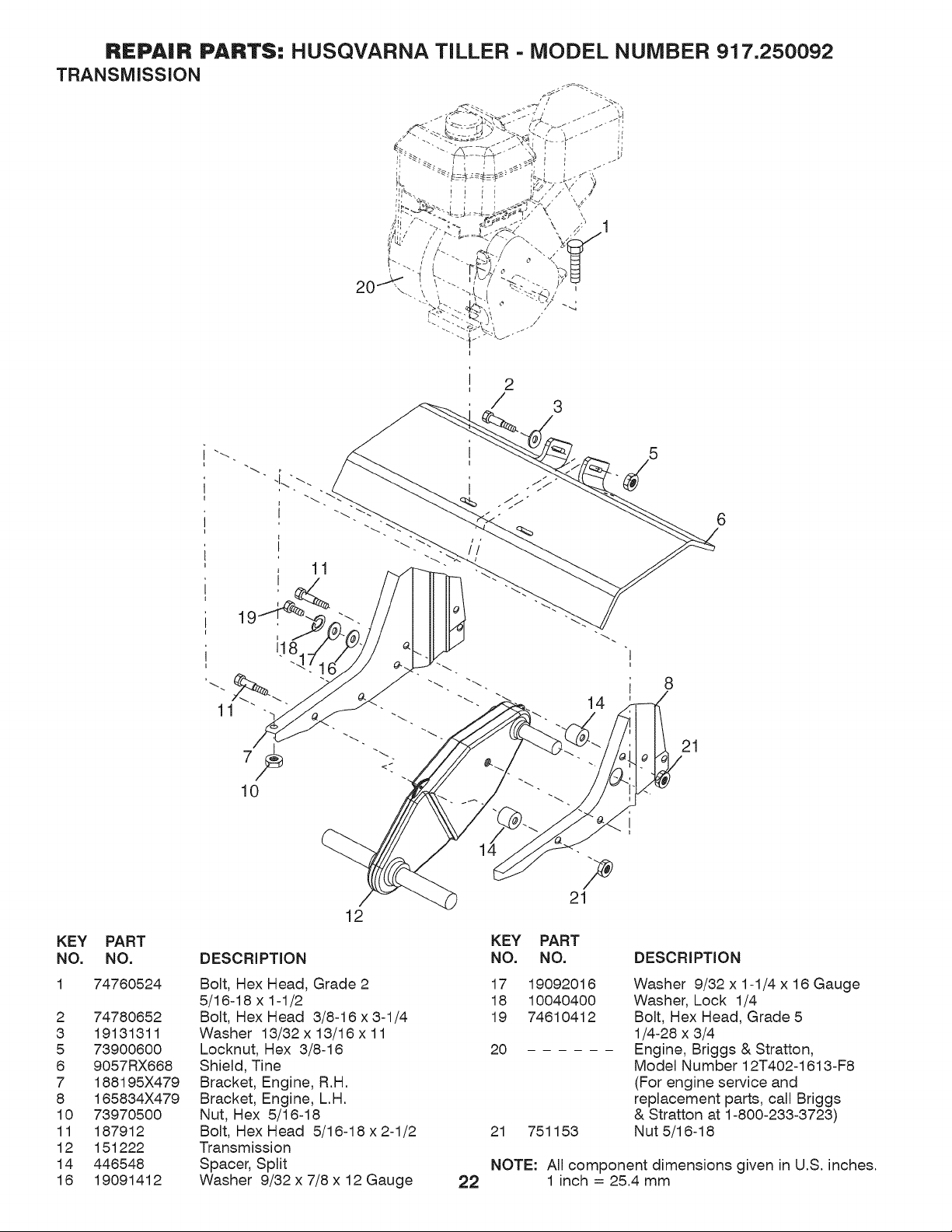
REPAIR PARTS: HUSQVARNA TILLER - MODEL NUMBER 917.250092
TRANSMiSSiON
', J_._ = = r J " / J'
i 2
I
/ 3
11
10
14
8
21
KEY
NO.
2
3
5
6
7
8
10
11
12
14
16
PART
NO.
74760524
74780652
19131311
73900600
9057RX668
188195X479
165834X479
73970500
187912
151222
446548
19091412
12
DESCRIPTION
Bolt, Hex Head, Grade 2
5/16-18 x 1-1/2
Bolt, Hex Head 3/8-16 x 3-1/4
Washer 13/32 x 13/16 x 11
Locknut, Hex 3/8-16
Shield, Tine
Bracket, Engine, R.H.
Bracket, Engine, L.H.
Nut, Hex 5/16-18
Bolt, Hex Head 5/16-18 x 2-1/2
Transmission
Spacer, Split
Washer 9/32 x 7/8 x 12 Gauge 22
KEY PART
NO. NO.
17 19092016
18 10040400
19 74610412
20
21 751153
DESCRIPTION
Washer 9/32 x 1-1/4 x 16 Gauge
Washer, Lock 1/4
Bolt, Hex Head, Grade 5
1/4-28 x 3/4
Engine, Briggs & Stratton,
Model Number 12T402-1613-F8
(For engine service and
replacement parts, call Briggs
& Stratton at 1-800-233-3723)
Nut 5/16-18
NOTE: All component dimensions given in U.S. inches.
1 inch = 25.4 mm
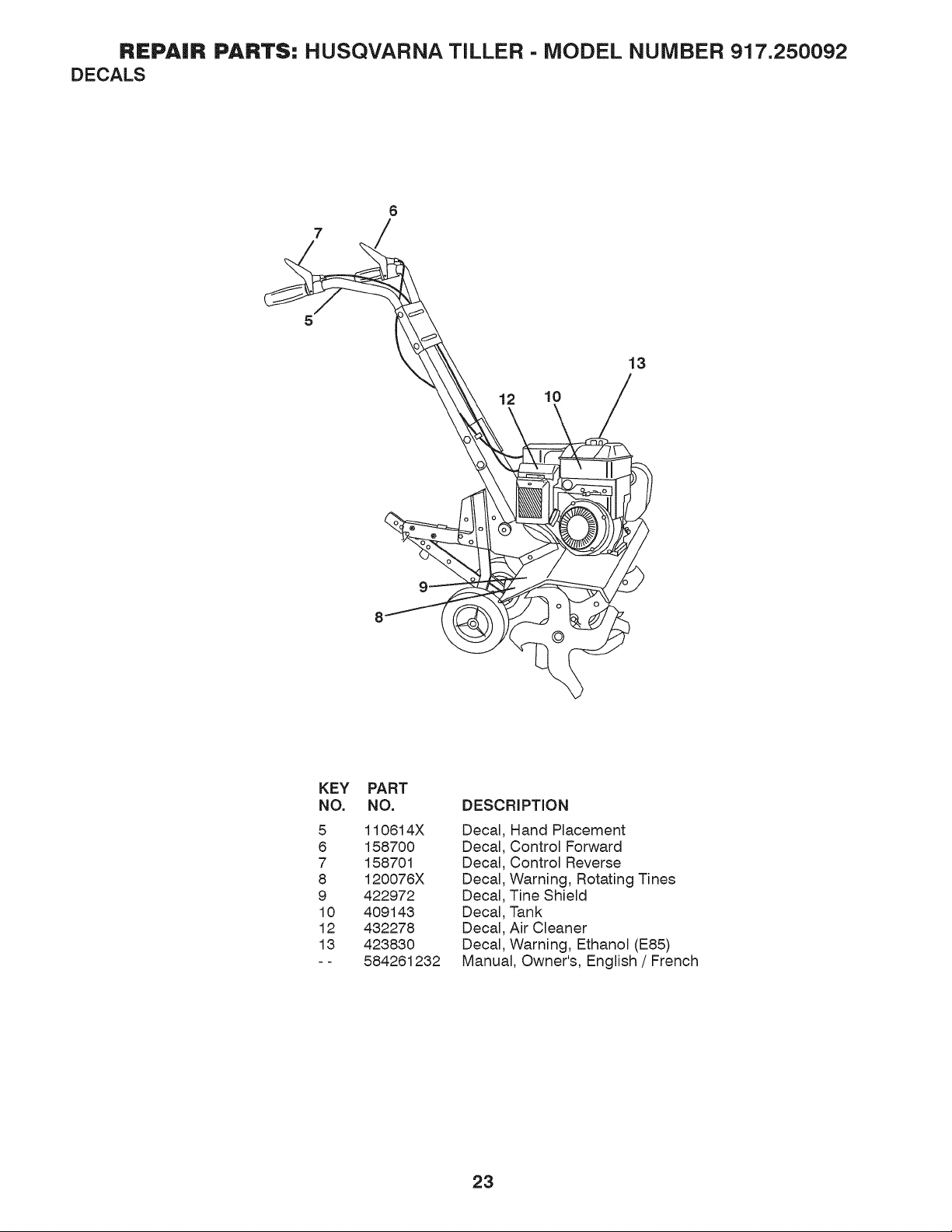
REPAIR PARTS: HUSQVARNA TILLER - MODEL NUMBER 917,250092
DECALS
12 10
13
KEY
NO.
5
8
7
8
9
10
12
13
PART
NO.
110614X
158700
158701
120076X
422972
409143
432278
423830
584261232
DESCRIPTION
Decal
Decal
Decal
Decal
Decal
Decal
Decal
Decal
Hand Placement
Control Forward
Control Reverse
Warning, Rotating Tines
Tine Shield
Tank
Air Cleaner
Warning, Ethanol (E85)
Manual, Owner's, English / French
23

Husqvarna
Consumer Wheeled Products - Limited Warranty
Husqvarna warrants to the original retail purchaser that this Husqvarna® product is free from defects in material or workmanship under normal use
and maintenance from the date of retail purchase for the applicable Warranty Period shown on Exhibit A. This Limited Warranty may not be transferred
to any subsequent purchaser of this Husqvarna® product. Certain components (e.g., engines and transmissions) are excluded from coverage, and other
limitations apply, as described in this docmnent. Husqvama will repair or replace at its discretion, any detective product or part covered by the Limited
Warranty, tree of charge at any authorized Husqvarna Servicing Dealer/Center using original OEM Husqvarna replacement parts, subject to the
limitations and exclusions described below. Husqvarna does not offer an over-the-counter exchange program.
DISCLAIMERS, LIMITATIONS AND EXCLI[ SIONS
l. WARRANTY DISCLAIMER. THIS LIMITED WARRANTY IS THE SOLE EXPRESS WARRANTY PROVIDED BY HUSQVARNA AND THERE ARE NO
WARRANTIES WHICH EXTEND BEYOND THE DESCRIPTION ON THE FACE HEREOF, EXCEPT AS MAY BE PROVIDED BY LAW. THIS WARRANTY IS
GIVEN ONLY BY HUSQVARNA, AND MAY BE MODIFIED ONLY BY HUSQVARNA. THIS LIMITED WARRANTY IS THE FINAL EXPRESSION OF OUR
AGREEMENT, AND IS A COMPLETE AND EXCLUSIVE STATEMENT OF THE TERMS OF THAT AGREEMENT. THIS LIMITED WARRANTY GIVES YOU
SPECIFIC LEGAL RIGHTS, AND YOU MAY ALSO HAVE OTHER RIGHTS WHICH VARY BASED ON LOCALITY
2. LIMITED DURATION. ANY WARRANTY THAT MAY BE IMPLIED BY LAW (INCLUDING ANY IMPLIED WARRANTY OF FITNESS FOR A
PARTICULAR PURPOSE OR USE AND IMPLIED WARRANTY OF MERCHANTABILITY) IS LIMITED TO THE DURATION OF THE APPLICABLE
WARRANTY PERIOD UNDER THIS LIMITED WARRANTY. SOME LOCALITIES DO NOT ALLOW LIMITATIONS ON HOW LONG AN IMPLIED
WARRANTY LASTS, SO THE ABOVE LIMITATIONS MAY NOT APPLY TO YOU.
3. EXCLI[ SIVE REMEDIES. SOME LOCALITIES, INCLUDING THE PROVINCE OF QUEBEC, DO NOT ALLOW THE EXCLUSION OR LIMITATION OF
LIABILITY FOR INJURY TO PERSON OR FOR DAMAGES RESULTING FROM THE FAULT OF THE MANUFACTURER AND/OR THE EXCLUSION OR
LIMITATION OF INCIDENTAL OR CONSEQUENTIAL DAMAGES. AS SUCH, SOME OF THE FOLLOWING LIMITATIONS MAY NOT APPLY TO YOU. THE
ABOVE REMEDIES ARE THE EXCLUSIVE REMEDIES FOR ANY BREACH OF THIS LIMITED WARRANTY. NO OTHER REMEDY, INCLUDING, BUT NOT
LIMITED TO ANY SPECIAL, INCIDENTAL, INDIRECT OR CONSEQUENTIAL DAMAGES, FOR LOST PROFITS, LOST SALES, INJURY TO PERSON OR
PROPERTY, OR ANY OTHER INCIDENTAL OR CONSEQUENTIAL LOSS SHALL BE AVAILABLE, AND ALL SUCH DAMAGES ARE HEREBY
DISCLAIMED.
4. Engines, Transmissions and certain other components are NOT covered. This Limited Wan'anty does not cover any of the following:
(a) Engit_es a_d Attachments.Except where otherwise indicated on Exhibit A. all Engines and Attachments are not covered by this Limited Wan'anty. In most cases, these
items are NOT manuf3ctured by Husqvama in which case they may be covered separately by their respective manufacturer's wan'anties if one is provided and included with
the product at the time of purchase. All such claims must be submitted and sent to the appropriate manufacturer or as otherwise directed in those separate warranties.
Husqvama is not authorized to handle wan'anty adjustments or repairs on engines manuf3ctured by Briggs & Stratton, Honda, Kawasaki, or Kohler (with the exception of
models equipped with LCT engines). Husqvama does not assume any wan'anty obligation of the other manufacturers' engines under this Limited Wan'anty.
(b) Trat_smissions. Except where otherwise indicated on Exhibit A, Transmission Transaxle (including Drive Systems) are not covered by this Limited Warranty. In most
cases, these items are NOT manuf3ctured by Husqvarna in which case they may be covered separately by their respective manuf3cturer's wan'anties if one is provided and
included with the product at the time of purchase. The following transmission / transaxle manuf;acturers, Dana, Hydro-Gear, Tuff-Torq provide a warranty for the
transmission / transaxle to the ultimate purchaser or to Husqvama. Husqvama will assign the transmission / transaxle manuf3cturer's warranty or any rights thereof to the
original purchaser of the unit. To obtain transmission / transaxle wan'anty service, first contact the retailer who you purchased the unit from. Should you require assistance
or have any questions concerning transmission / transaxle warranty coverage, contact Husqvama directly at our website www.husqvarna.com or call 800-48%5951 (US) or
800-805-5523 (Canada) for an authorized Husqvama service provider. All such claims must be submitted and sent to the appropriate manufacturer or as otherwise directed
in those separate warranties. Husqvarna is not authorized to handle wan'anty adjustments or repairs on transmissions or transaxles. Husqvarna does not assume any
obligations under this Limited Wan'anty for the above listed manuf3cturers (for exceptions - see Exhibit A).
(c) E._TJet_dable Parts. This Limited Warranty does not cover general maintenance parts and items ("Expendable Parts"), including without limitation spark plugs, bulbs,
filters, lubricants, starter cords, belts, blades, and blade adapters.
(d) Emissiot_s ('onrro/Components. This Limited Wan'anty does not cover Emissions control equipment and components to the extent regulated by the U.S. Enviromnental
Protection Agency or similar state, provincial or federal agencies. Such equipment and components are covered by a separate emission control wan'anty statement supplied
with your new product. Please consult this separate wan'anty statement for details.
5. Any COMMERCIAL, INSTITUTIONAL, AGRICULTURAL, INDUSTRIAL, INCOME PRODUCING, or RENTAL use will result in either
No Warranty or a Shortened Warranty Period. Depending on the product, there is either NO WARRANTY (whether statutory, contractual or
otherwise) or a reduced warranty if the product is used t\_r commercial, institutional, agricultural, industrial, income producing, or rental purposes and, in
such circumstances, this Limited Warranty is offered instead of and replaces any warranty regime provided for by law. Please refer to Exhibit A.
6. Reconditioned or Refurbished Products have a 30 Day Limited Warranty. Under this Limited Warranty, Certified Factory Reconditioned or
Refurbished products have a 30 Day Limited Warranty t\_r parts and labor t\_r Non-Commercial Use. Products are only reconditioned at the Husqvarna
Factory.
7. Owner's (Your) Responsibilities. To preserve your rights under this Limited Warranty, you must exercise reasonable care and use of the product,
including, t\+llowing the preventative maintenance, storage, fuel and oil usages as prescribed in the enclosed operator's manual. For example, the
t\+llowing items are the Owner's responsibility and are _ covered by this Limited Warranty:
a. Set-up and pro-delivery service, and engine tune-ups;
b. Adjustments after the first (30) thirty days of purchase and beyond, such as throttle cable, belt guides adjustments; and
c. Preventative maintenance as outlined in the operator's manual.
In addition, you must cease using the product immediately upon any failure or damage. The product should be taken to an authorized Husqvarna
sexa_icing dealer prior to any further use.
8. Damages resulting from normal aging, wear and tear or neglect are NOT covered. The Limited Warranty does not cover damage other than
that resulting fi:om detects in material or workmanship. The t\311owing are NOT considered detects in material or worl_nanship, and theret\3re are NOT
covered.
24
(a) Abrasion to mower decks;
(b) Tires damaged by external punctures;
(c) Natural discoloration of materials due to ultraviolet light;
(d) Dalnage to cutting equipment by way of contact with, rocks, or other non-approved materials and/or structures;
In addition, this Limited Warranty does not cover dalnages, malfanctions or failures resulting fi:om abuse or neglect of the product related to or including
any of the t\_llowing:
(e) Failure to provide or per%nn required maintenance services as prescribed in the operator's manual;
(1) Abuse, misuse, neglect, modifications, alterations, normal wear, improper servicing, use of unauthorized attachments, Lack of lubrication or
engine t:ailure, due to the use of oils that do not meet Engine manufacturer's specifications;
(g) Use of gasohol, containing methanol (wood alcohol). Gasohol which contains a maximum 10% ethanol (grain alcohol) or 15% MTBE
(methyl/tertiary/butyl/ether) is approved;
(h) Use of ether or any starting fluids;
(i) Pressure cleaning or stealn cleaning the product;
(i) Use of spark plugs other than those meeting emission pert\_rmance requirements listed in the operator's manual;
(k) Tampering with engine speed governor or emission components, or running engines above specified and recommended engine speeds as
listed in your operator's manual;
(1) Operation of the unit with improperly installed/removed or modified cutting shields, guards, or safety devices;
(m) Any removed/dalnaged air filter, excessive dirt, abrasives, salt water, moisture, corrosion, rest, varnish, stale fuel, or any adverse reaction due
to incorrect storage procedures;
(n) Failures due to improper set up, pre-delivery service or repair service by anyone other than an authorized Husqvarna servicing dealer during
the warranty period;
(o) Dirt contalninated grease or oil, use of incorrect type of greases or oils, t:ailure to comply with recommended greasing intel_als, water or
moisture damage, and/or improper storage;
(p) Sprayers pumping or spraying caustic or fkunmable materials, lack of or broken strainers; or
(q) Continued use of product, after initial operational problem or t:ailure occurs.
9. Reinforced Stamped (Armor Protected) 10 Year Limited & Fabricated Limited Lifetime, Deck Warranties. These Limited Warranties are t\_r
the deck shell only mechanical components/parts such as belts, pulleys, spindle housings, bearings, blades, rods, height adjusters, caster/anti scalp
wheels etc.., are NOT covered. The Limited Lifetime Warranty does not cover damage other than that resulting from detects in material or
workananship. The following are NOT considered detects in material or workananship, and therefore are NOT covered:
(a) Abrasion to mower decks, including sand wear;
(b) Dalnage to cutting equipment by way of contact with, rocks, or other non-approved materials and/or structures;
(c) Rust and corrosion; and
(d) Natural discoloration of paint or other materials due to ultraviolet light.
HOW TO OBTAIN SERVICE
10. Authorized Husqvarna Servicing Dealer/Center. In order to obtain warranty coverage it is your responsibility (at your expense) to deliver or ship
your Husqvarna unit to an authorized Husqvarna Servicing Dealer/Center and arrange t\_r pick-up or return of your unit after the repairs have been made.
If you do not know the location of your nearest authorized Husqvarna Servicing Dealer, call Husqvarna, at 1-800-487-5951 during the hours of 8:00 AM
to 8:00 PM Eastern Standard Time, or visit www.lmsqwm_a.com. Should you require assistance or have questions concerning this Limited Warranty, you
may contact us at 800-487-5951 (US) or 800-805-5523 (Canada) during the hours of 8:00 AM to 8:00 PM Eastern Standard Time or contact us through
the web at www.husqvama.com=
11. Documentation Required. You nmst maintain and present Proof of purchase (including date, product model and, if applicable, engine serial
number) to an authorized Husqvarna Servicing Dealer t\)r warranty service under this Limited Warranty. Proof of purchase rests solely with you.
Husqvarna encourages you to register your product online at www.usa.hus__ (US & Canada) to help ensure, among other things, that you can
be notified of important product information. However, registering your product is not a condition of warranty service.
Hz_sqvarna Professional Prodz¢cts, :\24, Ira:
_3 35 Har*'/s CoTveT_"PaJ'/__'_7>SI/lt(, 500, Chmiotte, _\-C2926 9
575 49 43-01 W2012][R
25
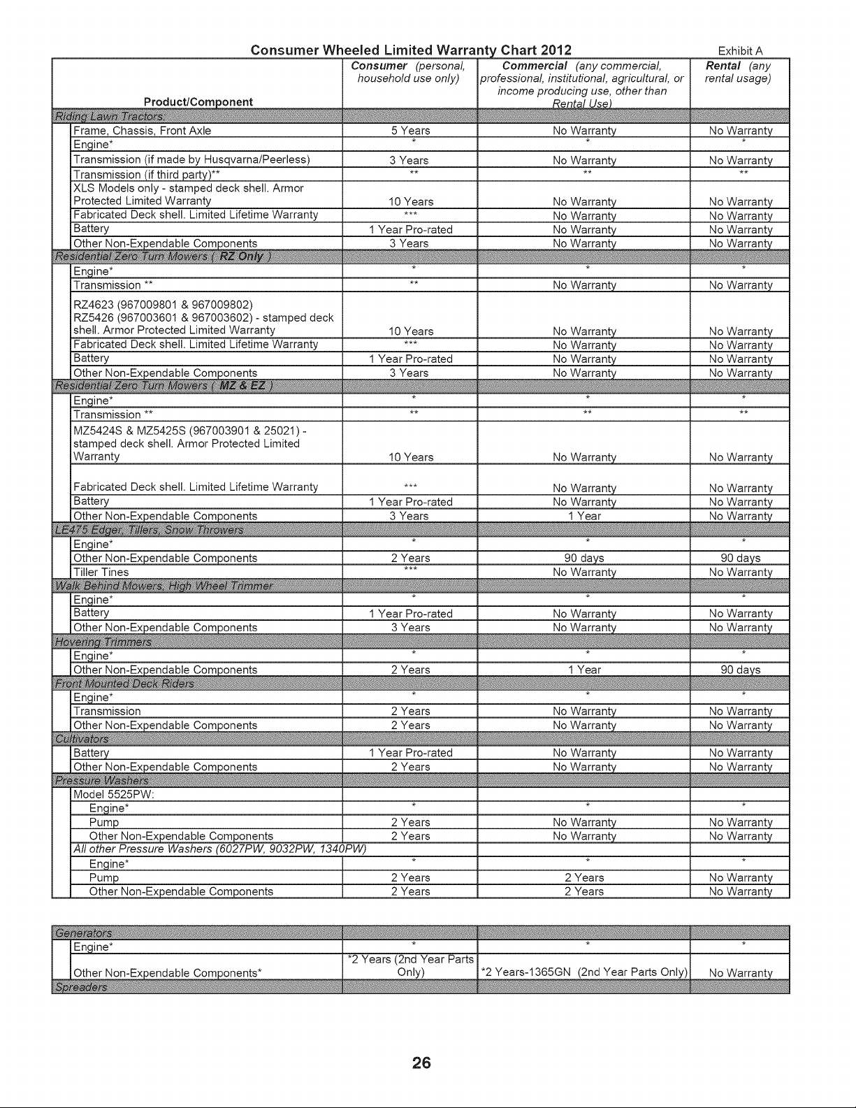
Consumer Wheeled Limited Warranty Chart 2012
Product/Component
Frame, Chassis, Front Axle
Engine*
Transmission (if made by Husqvarna/Peerless)
Transmission (if third party)**
XLS Models only - stamped deck shell. Armor
Protected Limited Warranty
Fabricated Deck shell. Limited Lifetime Warranty
Battery
Other Non-Expendable Components
Engine*
Transmission **
RZ4623 (967009801 & 967009802)
RZ5426 (967003601 & 967003602) - stamped deck
shell. Armor Protected Limited Warranty
Fabricated Deck shell. Limited Lifetime Warranty
Battery
Other Non-Expendable Components
Engine*
Transmission **
Consumer (personal
household use only)
5 Years
3 Years
10 Years
1 Year Pro-rated
3 Years
10 Years
1 Year Pro-rated
3 Years
Commercial (any commercial
professional institutional agricultural or
income producing use, other than
Rental Use2
No Warranty
No Warranty
No Warranty
No Warranty
No Warranty
No Warranty_
No Warranty
No Warranty
No Warranty
No Warranty
Exhibit A
Rental (any
rental usage)
No Warranty
No Warranty
No Warranty
No Warranty
No Warranty
No Warranty_
No Warranty
No Warranty
No Warranty
No Warranty
MZ5424S & MZ5425S (967003901 & 25021) -
stamped deck shell. Armor Protected Limited
Warranty
10 Years No Warranty No Warranty
Fabricated Deck shell. Limited Lifetime Warranty
Battery
Engine*
Other Non-Expendable Components
Tiller Tines
Engine*
Battery
Engine*
Other Non-Expendable Components
*** No Warranty
1 Year Pro-rated No Warranty
3 Years 1 Year
2 Years 90 days
No Warranty
1 Year Pro-rated
3 Years
No Warranty
2 Years 1 Year
No Warranty
No Warranty
90 days
No Warranty
_m
Engine*
Transmission
Battery
2 Years No Warranty
2 Years
1 Year Pro-rated No Warranty
2 Years
Model 5525PW:
Engine*
Pump
Other Non-Expendable Components
All other Pressure Washers (6027PW, 9032PW, 1340PW)
Engine*
Pump
Other Non-Expendable Components
No Warranty
No Warranty
I
No Warranty
2 Years No Warranty No Warranty
2 Years No Warranty No Warranty
2 Years 2 Years No Warranty
2 Years 2 Years No Warranty
26
Consumer Wheeled Limited Warranty Chart 2012
Product/Component
l Spreader
Consumer (personal
household use only)
1 Year
Commercial (any commercial
9rofessionaL institutional agricultural or
income producing use, other than
Rental Use}
1 Year
Robotic Mower
Battery
Accessories (e.g., grass catcher, bumper guard
accessories, etc.
Replacement parts and/or accessories provided
under this Limited Warranty are warranted only for
the BALANCE of the warranty period applicable to
the part or accessory that was replaced.
2 Years
1 Year
1 Year
See to left
Consumer
90 days
1 Year
No Warranty
No Warranty
See to left
Commercial
* See Separate Engine Manufacturer's or Manufacturer's warranty. LCT Engines on specific Snow Throwers & Tillers, warrant
Husqvarna.
** See reference 1 (b) of the warranty statement.
RZ - Two (2) Year Consumer warranty, parts & labor, with Hydro-Gear Distributor network.
EZ - One (1) Year Commercial warranty, parts & labor, with Husqvarna.
Two (2) Year Consumer warranty, parts & labor, with Hydro-Gear Distributor network.
MZ - Two (2) Year Commercial warranty, parts & labor, with Hydro-Gear Distributor network.
Exhibit A
Rental (any
rental usage)
1 Year
90 days
1 Year
No Warranty
See to left
Rental
through
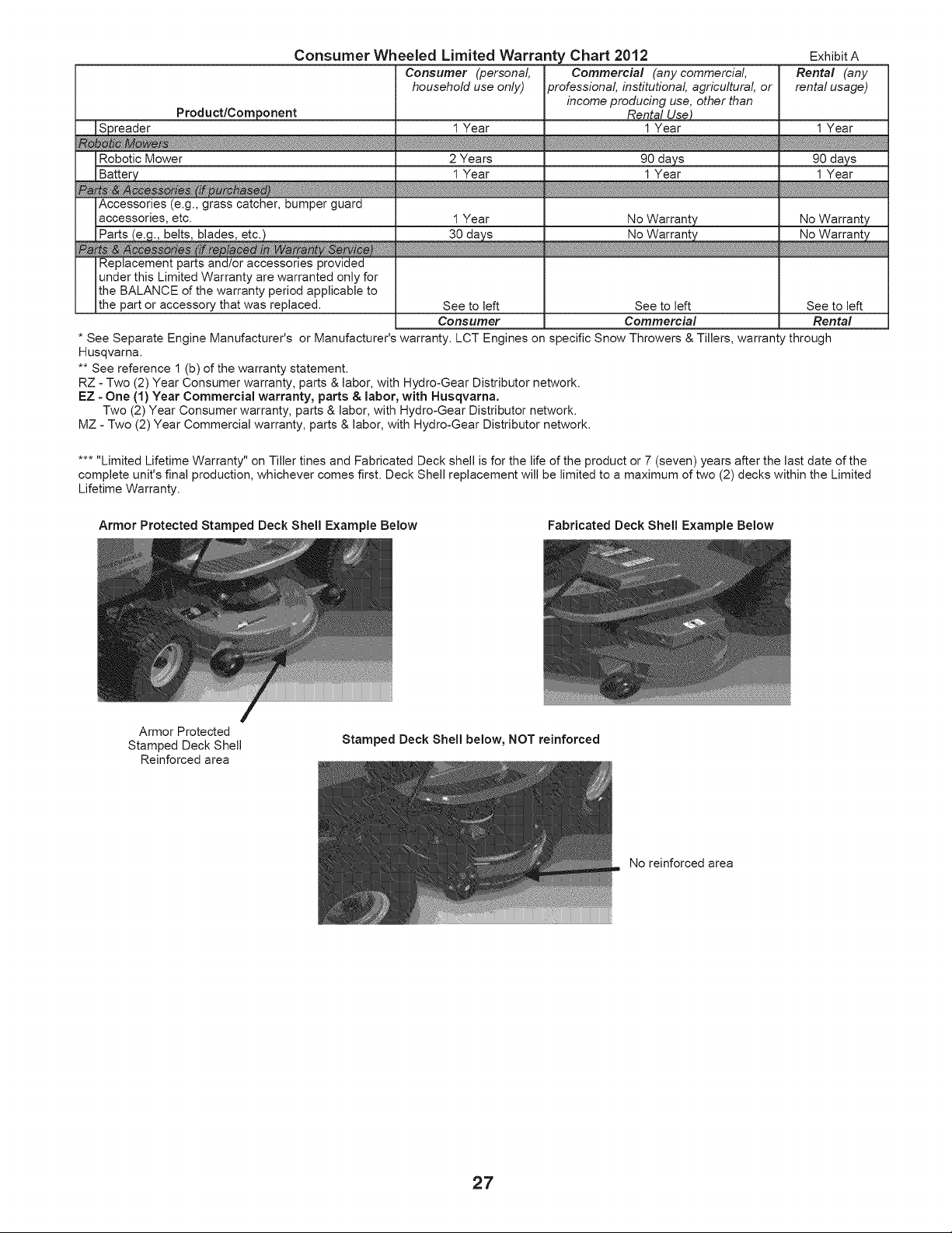
..... Limited Lifetime Warranty" on Tiller tines and Fabricated Deck shell is for the life of the product or 7 (seven) years after the last date of the
complete unit's final production, whichever comes first. Deck Shell replacement will be limited to a maximum of two (2) decks within the Limited
Lifetime Warranty.
Armor Protected Stamped Deck Shell Example Below Fabricated Deck Shell Example Below
Armor Protected
Stamped Deck Shell
Reinforced area
Stamped Deck Shell below, NOT reinforced
No reinforced area
27

RVIC NOTES
28
"_ f f
LES SEC ITE
CONSEILS POUR L'UTILISATION EN TOUTE SECURITE DES MOTOBINEUSES
FORMATION:
• Lisez soigneusement ce manuel. Familiarisez-vous avec les
commandes pour apprendre a utiliser efficacement votre
motobineuse. Apprenez comment I'arr6ter rapidement.
• N'autorisez jamais tes enfants a utilisert votre motobineuse.
Ne permettez pas que les aduttes I'utilisent s'ils n'ont pas
re(;u les instructions necessaires.
• Etoignez de la surface d'utilisation les animaux et les per-
sonnes et en particutier les petits enfants.
PRI_PARATION:
• V6rifiez syst6matiquement et soigneusement le terrain et
enlevez tousles objets 6trangers.
• D6brayez tousles embrayages et mettez la transmission en
position point mort avant de d_marrer le moteur.
• Habillez-vous avec des v6tements pratiques. Portez unique-
ment des chaussures sotides ayant une bonne traction.
• Soyez particuli_rement prudent lots de manipulation
d'essence; erie est inflammable.
• Utilisez un r6cipient d'essence approuv6.
• N'ajoutez jamais d'essence quand te moteur fonctionne et
laissez refroidir le moteur avant de remplir le r6servoir.
• Remptissez le r6servoir d'essence a t'ext6rieur. Ne remplissez
jamais le r6servoir & I'int6rieur d'un b&timent.
• Remettez le bouchon de r_servoir d'essence et essuyez
I'essence renversee avant de red,matter le moteur.
• Utilisez les cordons prolongateurs et les prises femelle selon
les specifications du fabricant pour toute machine a moteur
61ectrique (entratnement ou d_marrage 61ectrique).
• Ne tentez jamais de faire des r6glages quand te moteur
fonctionne (sauf quand un r_glage est recommand_ expli-
citement par le fabricant).
UTILISATION:
• Ne mettez pas les mains ou les pieds a. proximit_ ou sous
les parties mobiles.
• Faites attention lorsque vous traversez les all6es, les chemins,
les routes et toutes les surfaces couvertes de graviers. Ne
transportez jamais des passagers.
• Si vous heurtez un objet e'tranger, arr6tez imm_diatement
le moteur. D6branchez le c&ble de bougie d'atlumage et
inspectez la motobineuse, puis r_parez tous les dommages
avant de red,matter.
• Faites attention pour 6viter de gtisser ou tomber.
• N'utitisez pas votre motobineuse si ette vibre anormalement.
Arr6tez le moteur, recherchez ta cause des vibrations. Des
vibrations excessives sont les manifestations d'un probl_me
technique.
• Coupez te moteur quand vous quittez ta position d'utilisation.
• Prenez toutes les pr6cautions possibles quand vous laissez la
motobineuse sans surveillance. D6gagez les fraises, mettez
le levier de changement de vitesse a la position point mort,
et coupez le moteur.
• Avant de nettoyer, d'inspecter, ou de r6parer votre moto-
bineuse, coupez le moteur et assurez-vous que toutes les
parties mobiles soientarr6t6es. Ensuite, d6branchezle c&ble
de bougie d'atlumage et maintenez-le au loin de la bougie
pour eviter le d_marrage accidentel du moteur. D6branchez
le cordon d'alimentation sur les moteurs 61ectriques.
• Ne d_marrez pas le moteur a I'int6rieur d'un b&timent. Les
gaz d'6chappement sont dangereux.
• N'utilisez jamais votre motobineuse sans les d_flecteurs, les
plaques de protection, ou les autres dispositifs de s_curit_
en place.
• Etoignez les enfants et les animaux domestiques.
• Ne labourez pas trop profond_ment a grande vitesse. Vous
surchargerez la capacit_ productive de la motobineuse.
• Ne laissez jamais la motobineuse & grande vitesse quand la
surface est glissante. Regardez en arri_re et soyez prudent
en reculant.
• Ne laissez personne pros de la motobineuse Iorsque vous
I'utitisez.
• N'utilisez pas les accessoires qui ne sont pas recommand_s
par le fabricant.
• Utilisez la motobineuse seulement avec la lumi_re naturelle
ou artificielle suffisante.
• Faites attention quand vous labourez de la terre dure. Les
fraises peuvent s'accrocher dans ta terre et pousser la
motobineuse en avant. Darts ce cas, rel&chez tes poign_es
et ne retenez pas la machine.
ENTRETIEN ET ENTREPOSAGE:
• Conservez la motobineuse et les accessoires en bon fonc-
tionnement.
• V6rifiez fr6quemment que tousles boutons de cisaillement,
les boulons de montage de moteur, et les autres boulons
sont correctement serr6s.
• N'entreposez jamais a l'int6rieur d'un b_.timent une moto-
bineuse avec de l'essence darts le r6servoir. Les vapeurs
d'essence en provenance du r6servoir peuvent s'enflammer
au contact d'une flamme nue ou des appareils tets que
chauffe-eau, radiateurs etc. Laissez refroidir le moteur avant
de I'entreposer.
• Consuttez toujours le manuel du propri_taire pour les direc-
tives importantes quand la motobineuse dolt 6tre entrepos_e
Iongtemps.
- iMPORTANT-
ATTENTION, IMPORTANT, ET REMARQUE SONT UN MOYEN
D'ATTIRER VOTRE ATTENTION SUR DE L'INFORMATION
IMPORTANTE DANS CE MANUEL.
IMPORTANT: CE SYMBOLE ATTIRE VOTRE ATTENTION SUR
LES RISQUES DE DOMMAGES/_, L'EQUIPEMENT
REMARQUE: CE MOT ATTIRE VOTRE ATTENTION SUR
LA COMPREHENSION, L'INTEGRATION OU L'EXECUTION
D'INSTRUCTIONS.
Ce symbole signale les points irnportants en
mati_re de s_curit_. II signifie _ ATTENTION !!!,
SOYEZ PRUDENT !!! VOTRE SECURITE EST EN
JEU.
_ ATTENTION: D_branchez toujours le fil de bougie
d'allumage et pour pr_venir les d_marrages acci-
dentels, posez-le de telle fagon qu'il ne puisse
pas entrer en contact avec la bougie d'allumage
lots de rinstallation, du transport, des ajustements
ou des r_parations.
AVERTISSEMENT
II est connu par r_tat de Californie que les gaz d'6chap-
pement du moteur de ce produit contiennent des produits
chirniques lesquels, darts certaines quantit_s, peuvent
causer du cancer, de rinfirmit_ de naissance, et d'autre
endommagement du syst_me reproducteur.
29
SPi CIFICATIONS DU PRODUIT
Capacit6 et type 2,7 L (2.9 Qts. de Gallon)
d'essence: L'essence sans plomb normate
Type d'huile(APl:SG-SL): SAE30 (&ptus de 0°C/32°F)
Capacit_ d'huite:2Ooz.(0,6 L) 5W-30 (& moins de 0°C/32°F)
Bougie d'atlumage: Champion RC12YC
(Ecart: 0,030 po/0,762 mm)
FELICITATIONS pour votre achat d'une motobineuse. Elle a
6t6 con£_ue, perfectionn6e, et fabriqu_e pour assurer le bon
fonctionnement et la sOret_ maximum.
En cas d'un probteme quevous ne pouvez pas r_soudre, contactez
le centre d'entretien autoris6 le plus proche. Vous y trouverez
les techniciens qualifi6s et les outils appropri_s pour I'entretien
et la r_paration de cette machine.
Veuillez tire et conserver ce manuel. Les instructions qu I1contient
vous permettront de monter, et d'entret.enir correctement votre
motobineuse. Observez toujours les "REGLES DE SECURITE".
RESPONSABILITI'=S DU CLIENT
• Lisez et faites attention aux r_gles de s_curit6.
• Suivez un programme habituet d'entretien, de soin, et d'uti-
lisation de la motobineuse.
• Suivez les instructions dans les sections des Entretien et
d'Entreposage de ce manuel.
IMPORTANT: CETTE MACHINE EST MUNI D'UN MOTEUR
A COMBUSTION INTERNE ET NE DEVRAIT PAS ETRE
UTILISEE OU PRES D'UN TERRAIN COUVERT DES ARBR.ES,
DES ARBRISSEAUX, OU DES HERBES Sl LE SYSTEME
D'ECHAPPEMENT N'EST PAS MUNI D'UN PARE-ETINCELLES
RENCONTRANT LES EXIGENCES DES LOIS LOCALES
APPLICABLES. QUAND UN PARE-ETINCELLES EST UTILISE,
IL DEVRA[T ETRE MAINTENU EN BON FONCTIONNEMENT
PAR L'OPERATEUR.
VOIR LE CENTRE D'ENTRETIEN AUTORISE LE PLUS PROCHE
POUR LE PARE-ETINCELLES.
SO E
REGLES
f f
DE SECU, RITE ............................................. 29
RESPONSABILITES DU CLIENT ............................... 30
SPECIFICATIONS DU PRODUIT ............................... 30
MONTAGE ............................................................. 31-32
UTILISATION ......................................................... 33-36
CALENDRIER D'ENTRETIEN .................................... 37
EI_TRETIEM ...... _................................................... 37=39
REVISION ET REGLAGES .................................... 40-42
ENTREPOSA,GE ......................................................... 43
GUIDE DE DEPANNAGE ........................................... 44
PIECES DE RECHANGE ....................................... 45°50
GARANTIE ............................................................ 51-54
3O
MONTAGE
Votre nouvelle motobineuse a 6t6 mont6e & I'usine sauf certaines pi6ces en vue de t'expedition. Pour s'assurer d'une utilisation correcte
et sore de votre motobineuse, toutes les pi_ces et ferrures que vous assemblez doivent @re serr_es & fond. Utilisez les bons outils.
LES OUTILS EXIGES POUR LE MONTAGE
Un jeu des cl6s & douille facilitera t'assembtage. Les dimensions
normates des cl6s sont indiqu_es:
(1) Couteau & tout usage
(1) Tournevis
(1) Pince
(2) Oils de 1/2"
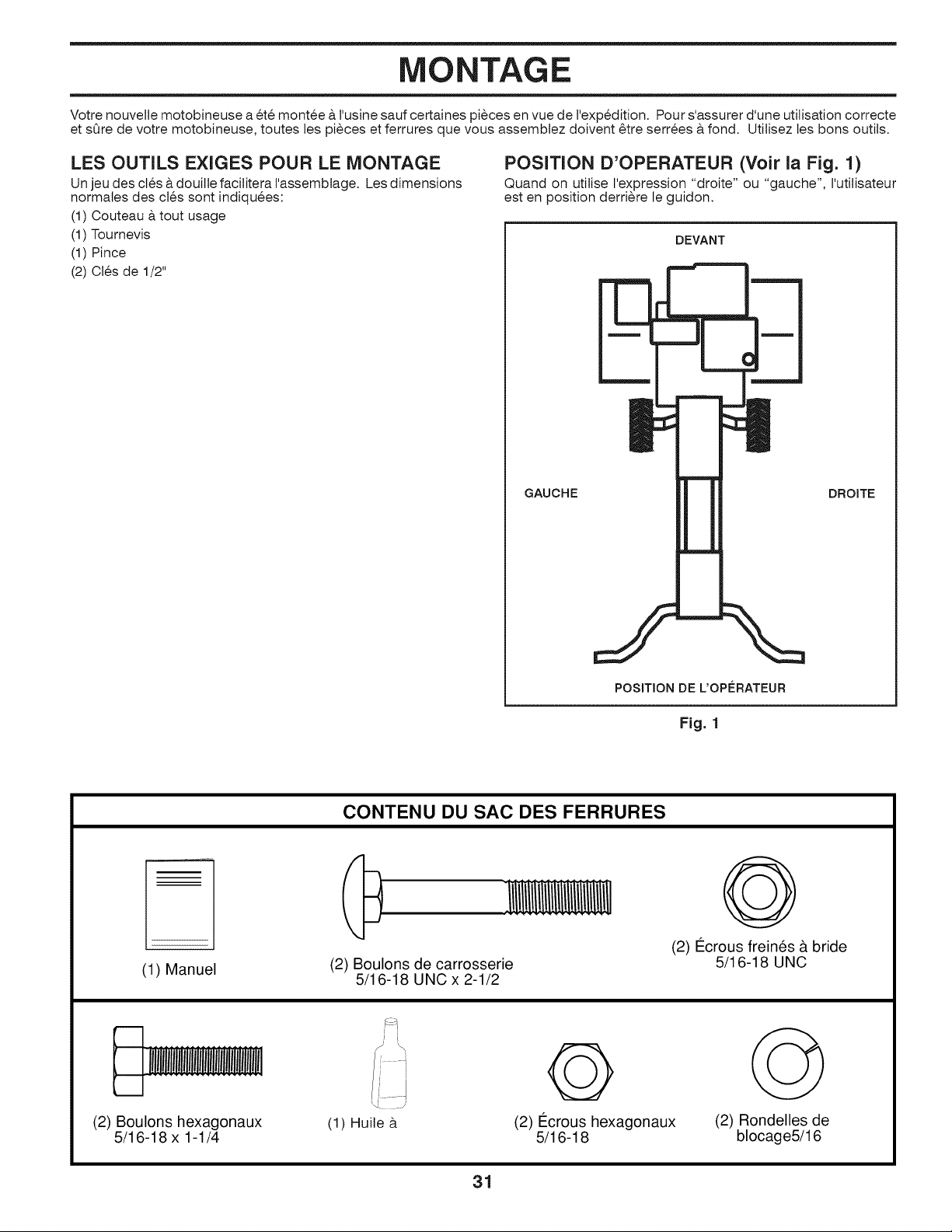
POSITION D'OPERATEUR (Voir la Fig. 1)
Quand on utilise I'expression "droite" ou "gauche", I'utilisateur
est en position derriere le guidon.
GAUCHE
DEVANT
DROITE
POSITION DE L'OPL=RATEUR
Fig. 1
CONTENU DU SAC DES FERRURES
(1) Manuel
(2) Boulons de carrosserie
5/16-18 UNC x 2-1/2
@
(2) I_crous freines & bride
5/16-18 UNC
(2) Boulons hexagonaux
5/16-18 x 1-1/4
(1) Huile &
@
(2) I_crous hexagonaux
5/16-18
(2) Rondelles de
blocage5/16
31
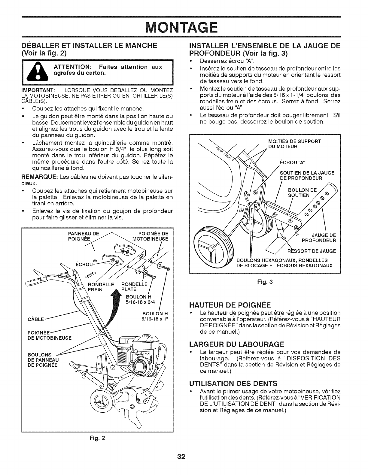
NTAGE
DEBALLER ET INSTALLER LE MANCHE
(Voir la fig. 2)
ATTENTION: Faites attention aux
agrafes du carton.
IMPORTANT: LORSQUE VOUS DEBALLEZ OU MONTEZ
MOTOBINEUSE,NE PAS ETIREROU ENTORTILLERLE(S)
CABLE(S).
* Coupez les attaches qui fixent le manche.
Le guidon peut 6tre monte dans la position haute ou
basse. Doucement levez I'ensemble du guidon en haut
et alignez les trous du guidon avec le trou et la fente
du panneau du guidon.
L&chement montez la quincaillerie comme montr&
Assurez-vous que le boulon H 3/4" le plus long soit
monte dans le trou inferieur du guidon. Repetez le
m6me procedure dans I'autre c6t& Serrez toute la
quincaillerie & fond.
REMARQUE: Les c&bles ne do!vent pas toucher le silen-
cieux.
Coupez les attaches qui retiennent motobineuse sur
la palette. Enlevez la motobineuse de la palette en
tirant en arriere.
Enlevez la vis de fixation du goujon de profondeur
pour faire glisser et el!miner la vis.
PANNEAU DE POIGNI_E DE
POIGNL=E MOTOBINEUSE
ECROU
CABLE
POIGN_:E
DE MOTOBINEUSE
BOULON H
5/16-18×1"
BOULONS
DE PANNEAU
DE POIGNL=E
INSTALLER L'ENSEMBLE DE LA JAUGE DE
PROFONDEUR (Voir la fig. 3)
• Desserrez ecrou "A".
• Inserez le soutien de tasseau de profondeur entre les
moities de supports du moteur en orientant le ressort
de tasseau vers le fond.
Montez le soutien de tasseau de profondeur aux sup-
ports du moteur AI'aide des 5/16 x 1-1/4" boulons, des
rondelles frein et des ecrous. Serrez A fond. Serrez
aussi I'ecrou "A".
• Le tasseau de profondeur dolt bouger librement. S'il
ne bouge pas, desserrez le boulon de soutien.
MOITII_S DE SUPPORT
"_., DU MOTEUR
ECROU'W'
SOUTIEN DE LAJAUGE
DE PROFONDEUR
BOULON DE
SOUTIEN
JAUGE DE
PROFONDEUR
RESSORT DE JAUGE
BOULONSHEXAGONAUX, RONDELLES
DE BLOCAGEETECROUSHEXAGONAUX
Fig. 3
HAUTEUR DE POIGNEE
* La hauteur de poignee peut _tre reglee & une position
convenable A I'operateur. (Referez-vous A"HAUTEUR
DE POIGNE_E"dans la section de Revision et Reglages
de ce manuel.)
LARGEUR DU LABOURAGE
* La largeur peut _tre regl6e pour vos demandes de
labourage. (Referez-vous A "DISPOSIT!ON DES
DENTS" dans la section de Revision et Reglages de
ce manuel.)
UTILISATION DES DENTS
Avant le primer usage de votre motobineuse, verifiez
I'utilisation des dents. (R6ferez-vous &"VERIFICATION
DE L'UTILISATION DE DENT" dans la section de Revi-
sion et Reglages de ce manuel.)
Fig. 2
32
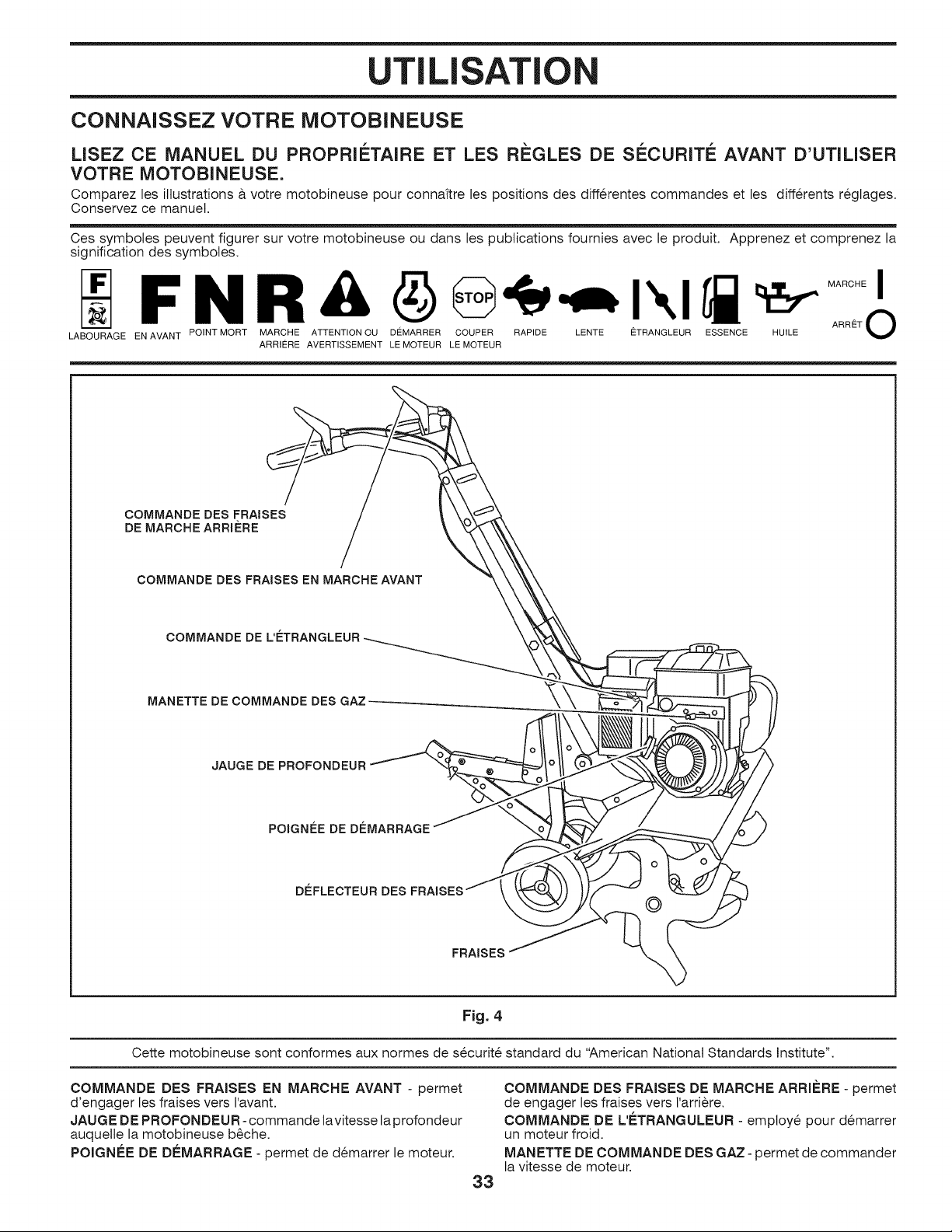
UTILISATI
CONNAISSEZ VOTRE MOTOBINEUSE
LISEZ CE MANUEL DU PROPRIETAIRE ET LES REGLES DE SECURITE AVANT D'UTILISER
VOTRE MOTOBINEUSE.
Comparez les illustrations & votre motobineuse pour connaftre les positions des diff_rentes commandes et les diff_rents r_glages.
Conservez ce manuel.
Ces symboles peuvent figurer sur votre motobineuse ou dans les publications fournies avec le produit. Apprenez et comprenez la
signification des symboles.
F N R A _ I _ ARRE_ToMARCHE
LABOURAGE EN AVANT POINT MORT MARCHE ATTENTION OU DEMARRER COUPER RAPIDE LENTE ETRANGLEUR ESSENCE HUILE
ARRIERE AVERTISSEMENT LE MOTEUR LE MOTEUR
COMMANDE DES FRAISES
DE MARCHE ARRI#RE
COMMANDE DES FRAISES EN MARCHE AVANT
COMMANDE DE
MANETTE DE COMMANDE DES GAZ .....
JAUGE DE PROFONDEUR
POIGNL=E DE DL=MARRAGE
DEFLECTEUR DES
©
FRAISES
Fig. 4
Cette motobineuse sont conformes aux normes de s_curit_ standard du "American National Standards Institute".
COMMANDE DES FRAISES EN MARCHE AVANT - permet
d'engager les fraises vers I'avant.
JAUGE DE PROFONDEUR - commande lavitesse la profondeur
auquelte la motobineuse b6che.
POIGNEE DE DEMARRAGE - permet de d_marrer le moteur.
33
COMMANDE DES FRAISES DE MARCHE ARRI#RE - permet
de engager les fraises vers I'arri_re.
COMMANDE DE L'ETRANGULEUR - employ_ pour d_marrer
un moteur froid.
MANETTE DE COMMANDE DES GAZ- permet de commander
la vitesse de moteur.
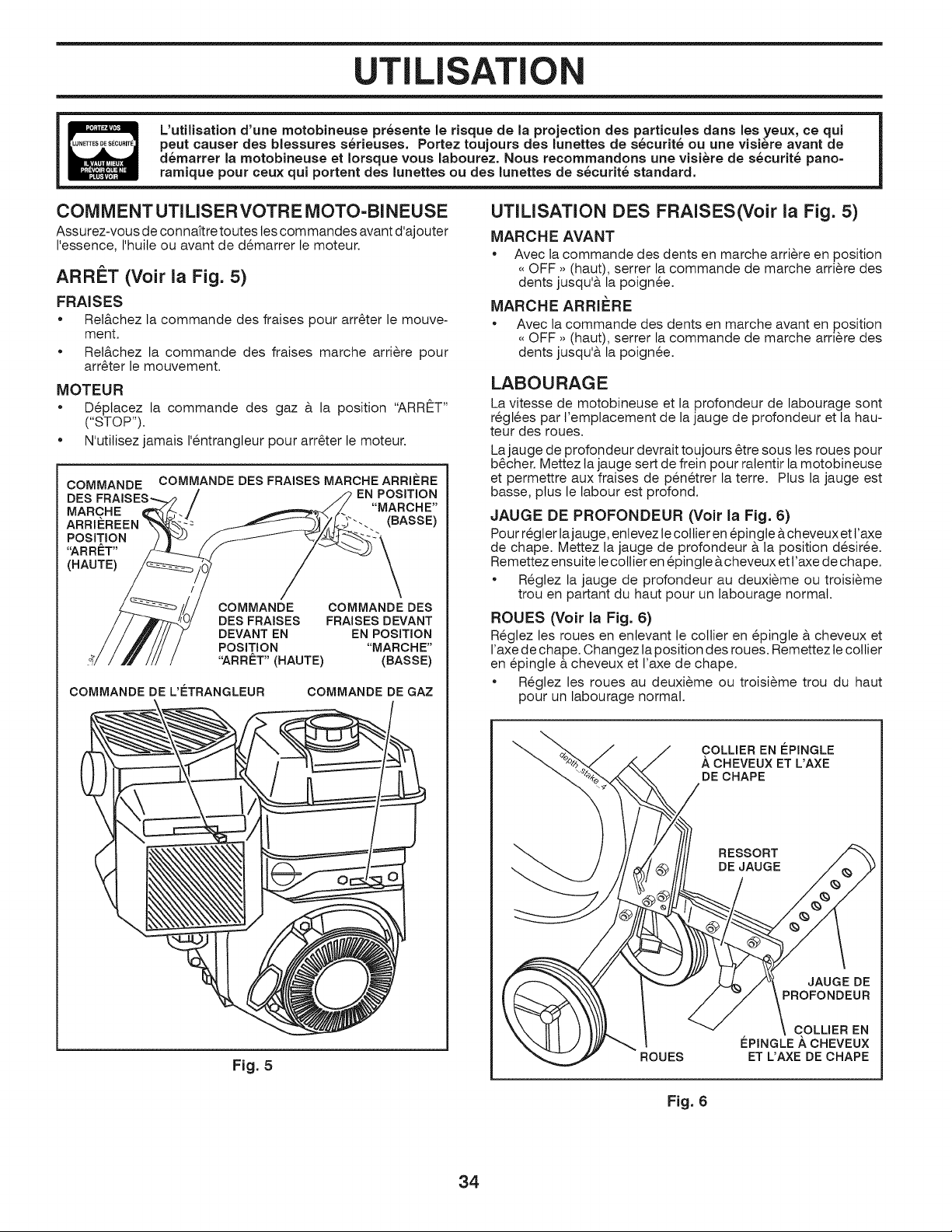
UTILISATI
L'utilisation d'une motobineuse pr_sente le risque de la projection des particules darts les yeux, ce qui
peut causer des blessures s_rieuses. Portez toujours des lunettes de s_curit_ ou une visie" re avant de
d_marrer la motobineuse et Iorsque vous labourez. Nous recommandons une visi_re de s_curit_ pano-
ramique pour ceux qui portent des lunettes ou des lunettes de s_curit_ standard.
UTILISATION DES FRAISES(Voir la Fig. 5)
COMMENTUTILISERVOTRE MOTO-BINEUSE
Assurez-vous de connaftre toutes tes commandes avant d'ajouter
I'essence, I'huile ou avant de d_marrer le moteur.
ARRET (Voir la Fig. 5)
FRAISES
• Rel&chez la commande des fraises pour arr_ter le mouve-
ment.
• Rel&chez la commande des fraises marche arri_re pour
arr6ter le mouvement.
IVIOTEUR
• D_placez la commande des gaz & la position "ARRET"
("STOP").
• N'utilisez jamais I'_ntrangleur pour arr6ter le moteur.
COMMANDE COMMANDE DES FRAISES MARCHE ARRIERE
DES EN POSITION
MARCHE "MARCHE"
(BASSE)
POSITION
"ARRET"
(HAUTE)
COMMANDE COMMANDE DES
DES FRAISES FRAISES DEVANT
DEVANT EN EN POSITION
POSITION "MARCHE"
"ARR#T" (HAUTE) (BASSE)
COMMANDE DE L'ETRANGLEUR COMMANDE DE GAZ
Fig. 5
MARCHE AVANT
• Avec la commande des dents en marche arri_re en position
,, OFF ,, (haut), serrer la commande de marche arri_re des
dents jusqu'& la poign_e.
MARCHE ARRIERE
• Avec la commande des dents en marche avant en position
,, OFF ,_(haut), serrer la commande de marche arri_re des
dents jusqu'& la poign_e.
LABO U RAG E
La vitesse de motobineuse et la profondeur de labourage sont
r6gl6es par t'emplacement de la jauge de profondeur et la hau-
teur des roues.
Lajauge de profondeur devrait toujours 6tre sous les roues pour
b6cher. Mettez ta jauge sert de frein pour ralentir la motobineuse
et permettre aux fraises de pen6trer la terre. Plus la jauge est
basse, plus le labour est profond.
JAUGE DE PROFONDEUR (Voir la Fig. 6)
Pour r6gler lajauge, enlevez le collier en 6pingte & cheveux et t'axe
de chape. Mettez la jauge de profondeur & la position d_sir_e.
Remettez ensuite le collier en 6pingle &cheveux et t'axe de chape.
• R_glez la jauge de profondeur au deuxi_me ou troisi_me
trou en partant du haut pour un labourage normal.
ROUES (Voir la Fig. 6)
Reglez les roues en enlevant le collier en 6pingle & cheveux et
I'axe de chape. Changez la position des roues. Remettez te collier
en _pingle & cheveux et I'axe de chape.
• Reglez les roues au deuxi_me ou troisi_me trou du haut
pour un labourage normal.
"'-_ COLLIER EN lePINGLE
A CHEVEUX ET L'AXE
DE CHAPE
RESSORT
DE JAUGE
JAUGE DE
ROUES
COLLIER EN
lePINGLE/_ CHEVEUX
ET L'AXE DE CHAPE
Fig. 6
34
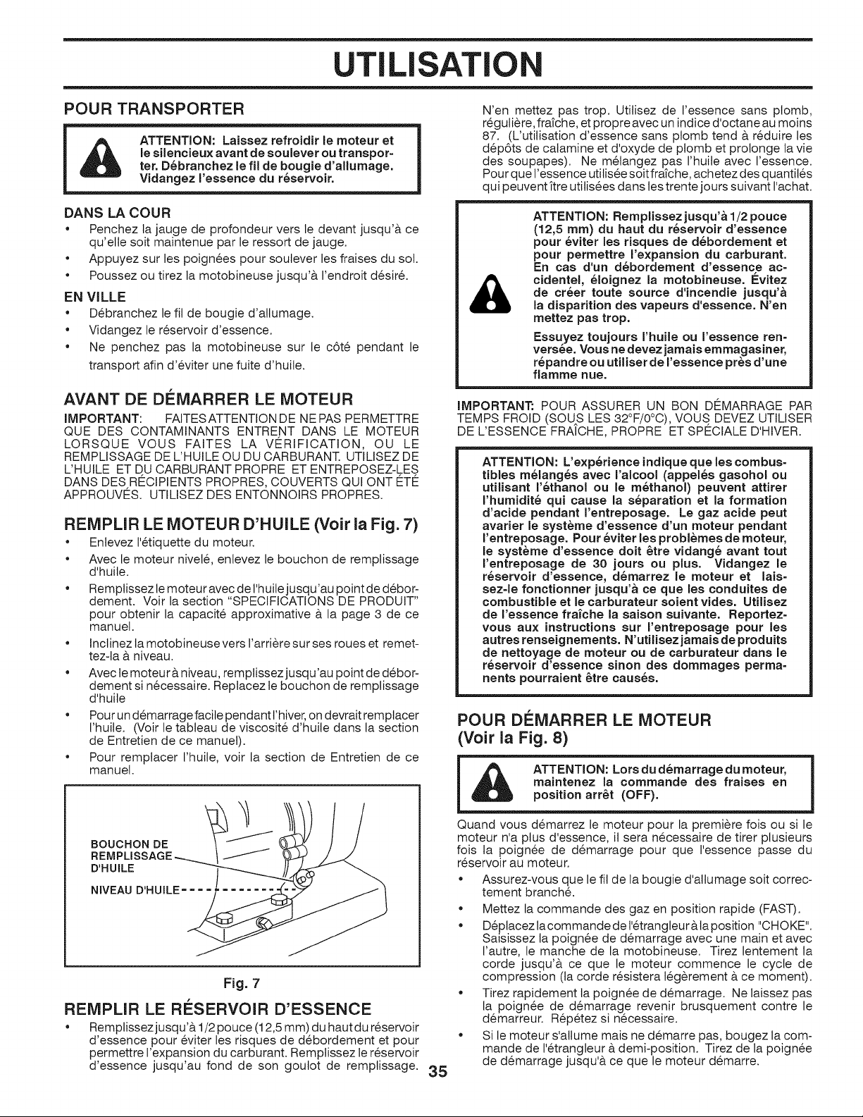
UTILISATI
POUR TRANSPORTER
ATTENTION: Laissez refroidir le moteur et
le silencieux avant de soulever ou transpor-
ter. D_branchez le fil de bougie d'allumage.
Vidangez I'essence du r_servoir.
DANS LA COUR
• Penchez ta jauge de profondeur vers le devant jusqu'& ce
qu'elte soit maintenue par le ressort de jauge.
• Appuyez sur les poign6es pour soutever les fraises du sot.
• Poussez ou tirez la motobineuse jusqu'& I'endroit d_sir&
EN VILLE
• D_branchez le fil de bougie d'allumage.
• Vidangez le r_servoir d'essence.
• Ne penchez pas la motobineuse sur le c6t_ pendant le
transport afin d'_viter une fuite d'huile.
AVANT DE DI_MARRER LE MOTEUR
IMPORTANT: FAITESATTENTION DE NEPAS PERMETTRE
QUE DES CONTAMINANTS ENTRENT DANS LE MOTEUR
LORSQUE VOUS FAITES LA VERIFICATION, OU LE
REMPLISSAGE DE L'HUILE OU DU CARBURANT. UTILISEZ DE
L'HUILE ET DU CARBURANT PROPRE ET ENTREPOSEZ-LES
DANS DES RECIPIENTS PROPRES, COUVERTS QUI ONT ETE
APPROUVES. UTILISEZ DES ENTONNOIRS PROPRES.
REiVIPLIR LE MOTEUR D'HUILE (Voir la Fig. 7)
• Enlevez 1'6tiquette du moteur.
Avec le moteur nivel_, enlevez le bouchon de remplissage
d'huile.
• Remplissez le moteur avec de I'huitejusqu'au point de d6bor-
dement. Voir la section "SPECIFICATIONS DE PRODUIT"
pour obtenir la capacit_ approximative a la page 3 de ce
manuel.
• Inctinez la motobineuse vers l'arri_re sur ses roues et remet-
tez-ta & niveau.
• Avec te moteur a niveau, remptissez jusqu'au point de d_bor-
dement si n_cessaire. Reptacez le bouchon de remplissage
d'huile
• Pour un d_marrage facile pendant t'hiver, on devrait remplacer
I'huite. (Voir le tableau de viscosit_ d'huite dans la section
de Entretien de ce manuel).
• Pour remplacer I'huite, voir la section de Entretien de ce
manuel.
BOUCHON DE
REMPLISSAGE -_
D'HUILE
NIVEAU D'HUILE = =
Fig. 7
REMPLIR LE RESERVOIR D'ESSENCE
• Remplissez jusqu'& 1/2 pouce (12,5 mm) du haut du r6servoir
d'essence pour 6viter les risques de debordement et pour
permettre I'expansion du carburant. Remplissez le r6servoir
d'essence jusqu'au fond de son goulot de remplissage. 35
N'en mettez pas trop. Utilisez de I'essence sans ptomb,
r6guti_re, frafche, et propre avec un indice d'octane au moins
87. (L'utitisation d'essence sans ptomb tend & r6duire les
d_p6ts de calamine et d'oxyde de plomb et protonge la vie
des soupapes). Ne metangez pas I'huite avec I'essence.
Pour que I'essence utitisee soit frafche, achetez des quantil6s
qui peuvent ftre utitis_es dans les trente jours suivant I'achat.
&
ATTENTION: Remplissezjusqu'& 1/2 pouce
(12,5 ram) du haut du r_servoir d'essence
pour _viter les risques de d_bordement et
pour permettre I'expansion du carburant.
En cas d'un d_bordement d'essence ac=
cidentel, _loignez la motobineuse. #vitez
de crier toute source d'incendie jusqu'&
la disparition des vapeurs d'essence. N'en
mettez pas trop.
Essuyez toujours rhuile ou I'essence ren-
versee. Vous ne devez jamais emmagasiner,
r_pandre ou utiliser de I'essence pros d'une
flamme hue.
iMPORTANT: POUR ASSURER UN BON DC:MARRAGE PAR
TEMPS FROID (SOU S LES 32°F/0°C), VOUS DEVEZ UTILISER
DE L'ESSENCE FRAICHE, PROPRE ET SPECIALE D'HIVER.
ATTENTION: L'exp6rience indique que lea combus-
tibles m61ang6s avec I'alcool (appel6s gasohol ou
utilisant r6thanol ou le m6thanol) peuvent attirer
rhumidit6 qui cause la s6paration et la formation
d'acide pendant I'entreposage. Le gaz acide peut
avarier le syst_me d'essence d'un moteur pendant
rentreposage. Pour 6viter les probl_mes de moteur,
le syst_me d'essence doit 6tre vidang6 avant tout
rentreposage de 30 jours ou plus. Vidangez le
r6servoir d'essence, d6marrez le moteur et lais-
sez-le fonctionner jusqu'& ce que les conduites de
combustible et le carburateur soient vides. Utilisez
de I'essence frai'che la saison suivante. Reportez-
vous aux instructions sur rentreposage pour les
autres renseignements. N'utilisez jamais de produits
de nettoyage de moteur ou de carburateur dans le
r6servoir d'essence sinon des dommages perma-
nents pourraient 6tre caus6s.
POUR DEIVIARRER LE MOTEUR
(Voir la Fig. 8)
ATTENTION: Lots du d6marrage du moteur,
maintenez la commande des fraises en
position arr6t (OFF).
Quand vous d_marrez le moteur pour la premiere fois ou si le
moteur n'a plus d'essence, il sera necessaire de tirer plusieurs
fois la .poign6e de d_marrage pour que I'essence passe du
r_servolr au moteur.
• Assurez-vous que le fil de la bougie d'atlumage soit correc-
tement branch,.
• Mettez la commande des gaz en position rapide (FAST).
• D_placez la commande de l'_trangleur &ta position "CHOKE".
Saisissez la poign_e de d_marrage avec une main et avec
I'autre, le manche de la motobineuse. Tirez lentement la
corde jusqu'& ce que le moteur commence le cycle de
compression (la corde r_sistera teg_rement & ce moment).
• Tirez rapidement ta poign_e de d_marrage. Ne laissez pas
la poign_e de d_marrage revenir brusquement contre le
d_marreur. R_p6tez si n_cessaire.
• Si le moteur s'allume mais ne demarre pas, bougez la com-
mande de I'etrangleur & demi-position. Tirez de la poign_e
de d_marrage jusqu'& ce que le moteur d_marre.
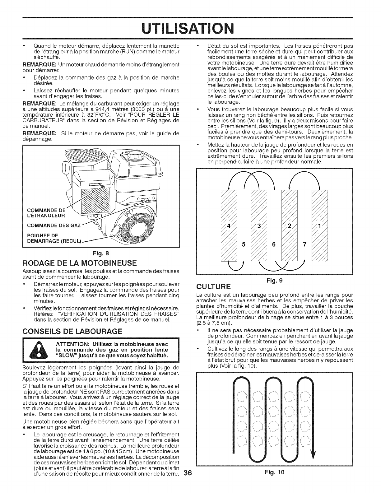
UTILISATI
,, Quand le moteur d_marre, d6placez lentement la manette
de 1'6trangteur &la position marche (RUN) comme le moteur
s'6chauffe.
REMARQUE: Un moteur chaud demande moins d'_tranglement
pour d_marrer.
• D_placez la commande des gaz a la position de marche
d_sir6e.
• Laissez r6chauffer le moteur pendant quelques minutes
avant d'engager les fraises.
REMARQUE: Le melange du carburant peut exiger un r6gtage
& une altitudes superieure a 914,4 m_tres (3000 pi.) ou & une
temp6rature inf6rieure a 32°F/0°0. Voir "POUR REGLER LE
CARBURATEUR" dans la section de R_vision et R_glages de
ce manuel.
REMARQUE: Si le moteur ne d_marre pas, voir le guide de
d_pannage.
COMMANDE DE
L'E_TRANGLEUR
COMMANDE DES
POIGNEE DE
DEMARRAGE (RECUL'
Fig. 8
RODAGE DE LA MOTOBINEUSE
Assouplissez la courroie, les poulies et la commande des fraises
avant de commencer le labourage.
• D_marrez le moteur, appuyez sur les poign6es pour soutever
les fraises du sot. Engagez la commande des fraises pour
les faire toumer. Laissez tourner les fraises pendant cinq
minutes.
• V6rifiez le fonctionnement des fraises et r6glez si n_cessaire.
R6f6rez "VERIFICATION D'UTILISATION DES FRAISES"
dans la section de R_vision et R_glages de ce manuel.
CONSEILS DE LABOURAGE
I ATTENTION: Utilisez la motobineuse avec
!a com,,m..andedes gaz en position lente |
SLOW jusqu ace que vous soyez habitue.
Soulevez 16g_rement les poign6es (levant ainsi la jauge de
profondeur de la terre) pour aider la motobineuse & avancer.
Appuyez sur les poignees pour ralentir la motobineuse.
S'il faut faire un effort ou si la motobineuse tremble, les roues et
la jauge de profondeur NE sont PAS correctement ancr6es dans
la terre & labourer. Vous arrivez & un r6glage correct de la jauge
et des roues par des essais et selon I'etat de la terre. Si ta terre
est dure ou mouill6e, la vitesse du moteur et des fraises sera
lente. Dans ces conditions, la motobineuse sautera sur le sot.
Une motobineuse bien r_gl_e b6chera sans que I'op6rateur ait
& exercer un gros effort.
• Le labourage est le creusage, le retournage et l'effritement
de la terre durci avant I'ensemencement. Une terre d61i6e
favorise la croissance des racines. La meilleure profondeur
de labourage est de 4 & 6 po. (10 & 15 cm). Une motobineuse
aide aussi &enlever les mauvaises herbes. La d_composition
de ces mauvaises herbes enrichit le sol. D6pendant du ctimat
(ptuie et vent) il peut 6tre pr6f_rabte de labourer la terre &la fin
d'une saison de r_colte pour mieux conditionner de la terre.
• L'_tat du sot est importantes. Les fraises p_n6treront pas
facitement une terre s6che et dure qui peut contribuer aux
rebondissements exag6r6s et & un maniement difficile de
votre motobineuse. Une terre dure devrait _tre humidifi6e
avant le tabourage, et une terre extr6mement mouill6 formera
des boules ou des mottes durant le labourage. Attendez
jusqu'& ce que la terre soit moins mouitle afin d'obtenir les
meilleurs r6sultats. Lorsque le labourage se fait & t'automne,
enlevez les vignes et les Iongues herbes pour emp_cher
celles-ci de s'enrouler autour de l'arbre des fraises et ratentir
le labourage.
• Vous trouverez le labourage beaucoup plus facile si vous
laissez un rang non b_ch6 entre les siltons. Puis retournez
entre les sitlons (Volt la fig. 9). II y a deux raisons pour faire
ceci. Premi_rement, des virages larges sont beaucoup plus
faciles & prendre que des demi-tours. Deuxi_mement, la
motobineuse ne vous entrafnera pas vers le rang plus proche.
• Mettez la hauteur de la jauge de profondeur et les roues en
position pour labourage peu profond Iorsque la terre est
extr6mement dure. Travaillez ensuite les premiers sillons
en perpendiculaire & une profondeur normate.
// /
// /
// /
/./ /
// /
// /
/./ /
// /
// /
/ / / /./'
// /
// /
// /
/./
//
// //
//
CULTURE
Fig. 9
La culture est un labourage peu profond entre les rangs pour
arracher les mauvaises herbes et les emp_cher de priver les
plantes d'humidit6 et d'aliments. De plus, travailter la couche
superieure de laterre contribuera & la conservation de l'humidit&
La meilleure profondeur de binage se situe entre 1 & 3 pouces
(2,5 & 7,5 cm).
• IIne sera pas n6cessaire probabtement d'utiliser la jauge
de profondeur. Commencez en penchant en avant la jauge
jusqu'& ce qu'elle soit tenue par le ressort de jauge.
• Cuttivez le long des rangs & une vitesse qui permettra aux
fraises de d6raciner les mauvaises herbes et de laisser laterre
& l'6tat brut pour que les mauvaises herbes n'y repoussent
plus (Voir la fig. 10).
36 Fig. 10
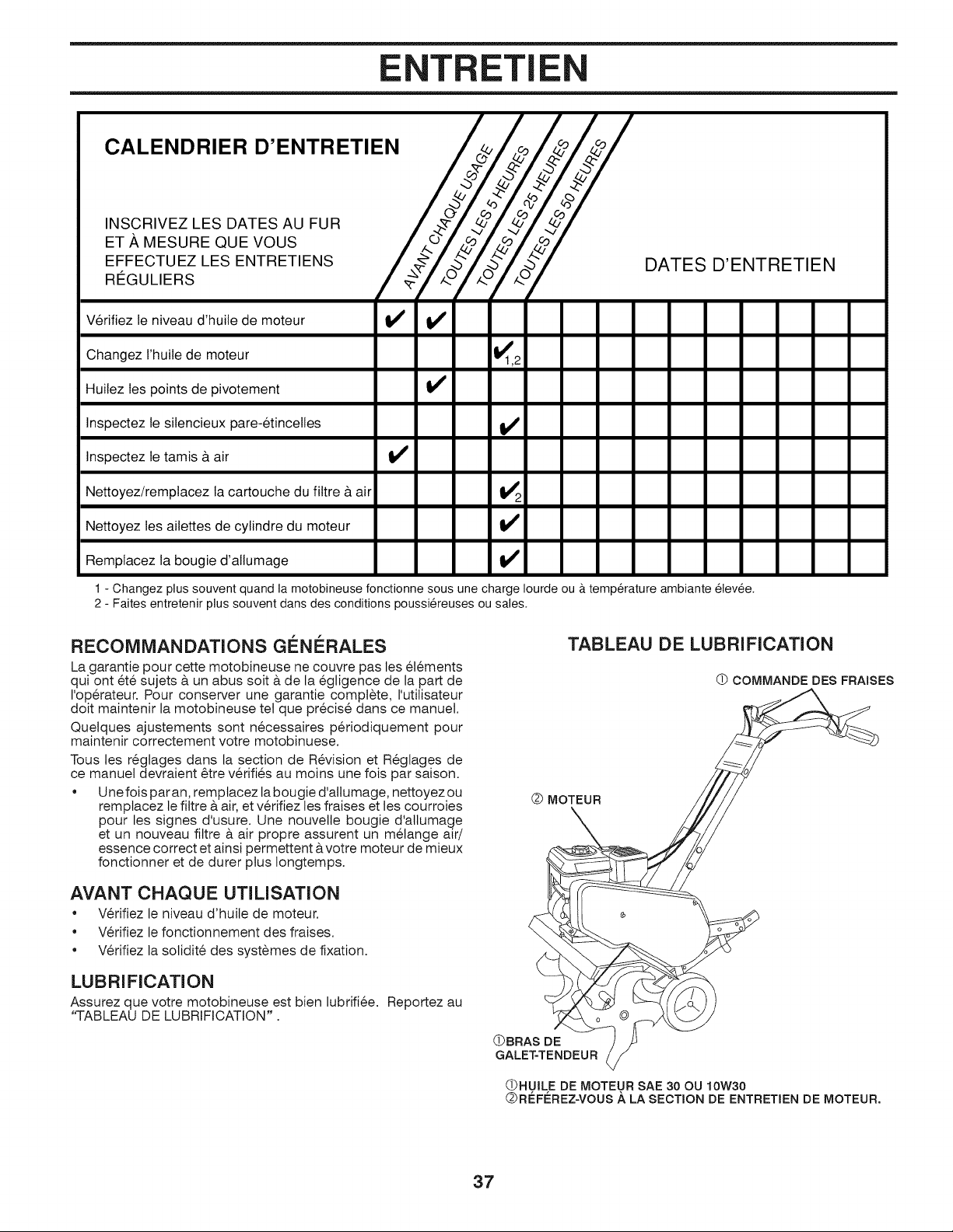
TRETI
CALENDRIER D'ENTRETIEN /o_Z_4_Z_ /
/ TJ/ lJ
ISI
INSCRIVEZ LES DATES AU FUR / -._'_//-_//-_//-_/
ET ,g, MESURE QUE VOUS / ko.<-/ w/-v/-v/
E FFECTUEZ LES ENTRETIENS 4_/.b/"_°_!_z'_/.b/"_°_/
.E U.,E.S / ,/ o7 o7 o7
Verifiez le niveau d'huile de moteur if V _
Changez I'huile de moteur _1,2
Huilez les points de pivotement V P
DATES D'ENTRETIEN
Inspectez le silencieux pare-etincelles if
Inspectez le tamis & air if
Nettoyez!remplacez la cartouche du filtre & air _2
Nettoyez les ailettes de cylindre du moteur if
Remplacez la bougie d'allumage if
1 - Changez plus souvent quand la motobineuse fonctionne sous une charge Iourde ou & temperature ambiante elevee.
2 - Faites entretenir plus souvent dans des conditions poussiereuses ou sales.
RECOMMANDATIONS GENERALES
La garantie pour cette motobineuse ne couvre pas les 6t6ments
qui ont 6t6 sujets & un abus soit & de la egligence de la part de
I'op@ateur. Pour conserver une garantie complete, I'utitisateur
dolt maintenir la motobineuse tel que pr6cis_ dans ce manuel.
Quetques ajustements sont n6cessaires p@iodiquement pour
maintenir correctement votre motobinuese.
Tousles r_gtages dans la section de R6vision et R6glages de
ce manuel devraient @re v@ifi_s au moins une fois par saison.
• Une fois par an, remptacez la bougie d'allumage, nettoyez ou
remplacez le filtre a air, et v@ifiez les fraises et les courroies
pour les signes d'usure. Une nouvelle bougie d'allumage
et un nouveau filtre a air propre assurent un melange air/
essence correct et ainsi permettent avotre moteur de mieux
fonctionner et de durer plus longtemps.
AVANT CHAQUE UTILISATION
" V@ifiez le niveau d'huite de moteur.
• V@ifiez le fonctionnement des fraises.
• V@ifiez la solidit_ des syst_mes de fixation.
LUBRIFICATION
Assurez que votre motobineuse est bien lubrifi_e. Reportez au
"TABLEAU DE LUBRIFICATION".
(_ MOTEUR
TABLEAU DE LUBRIFICATION
(_ COMMANDE DES FRAISES
(_BRAS DE
GALET-TENDEUR
(_HUILE DE IVIOTEUR SAE 30 OU 10W30
(_R#FL=REZ=VOUS A LA SECTION DE ENTRETIEN DE MOTEUR.
37
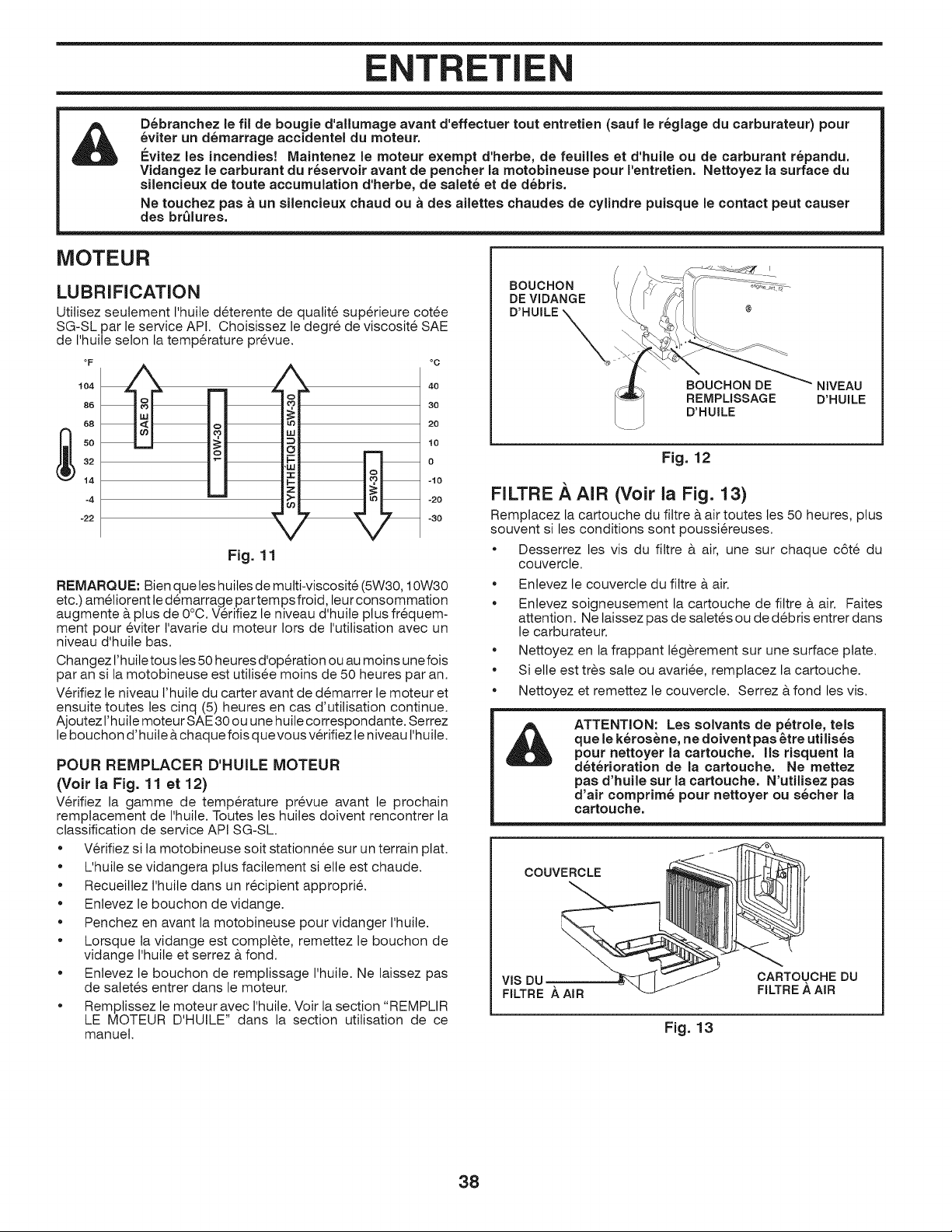
ENTRETIE
D_branchez le fil de bougie d'allumage avant d'effectuer tout entretien (sauf le r_glage du carburateur) pour
_viter un d_marrage accidentel du moteur.
Evitez les incendies! Maintenez le moteur exempt d'herbe, de feuilles et d'huile ou de carburant r_pandu.
Vidangez le carburant du r_servoir avant de pencher la motobineuse pour I'entretien. Nettoyez la surface du
silencieux de toute accumulation d'herbe, de salet_ et de d_bris.
Ne touchez pas a un silencieux chaud ou a des ailettes chaudes de cylindre puisque le contact peut causer
des br_lures.
MOTEUR
LUBRIFICATION
Utitisez seutement I'huile deterente de quatit_ sup_rieure cotee
SG-SL par le service API. Choisissez le degr_ de viscosit_ SAE
de I'huite selon la temp6rature pr_vue.
°O
104
86
68
32
14
-4
-22
40
30
20
10
0
-10
-20
-30
Fig. 11
REMARQUE: Bien queles huites de multi-viscosit_ (5W30, 10W30
etc.) am_tiorent le d_marrage par temps froid, leur consommation
augmente & plus de 0°C. V6rifiez le niveau d'huite plus fr6quem-
ment pour 6viter t'avarie du moteur Iors de I'utilisation avec un
niveau d'huile bas.
Changez l'huile tous tes 50 heures d'operation ou au moins une fois
par an si la motobineuse est utilis6e moins de 50 heures par an.
V6rifiez le niveau t'huite du carter avant de d_marrer le moteur et
ensuite toutes les cinq (5) heures en cas d'utitisation continue.
Ajoutez l'huile moteur SAE 30 ou une huile correspondante. Serrez
le bouchon d'huite &chaque fois quevous v_rifiez te niveau t'huile.
POUR REMPLACER D'HUILE MOTEUR
(Volt la Fig. 11 et 12)
V_rifiez la gamme de temperature pr6vue avant le prochain
remptacement de I'huile. Toutes les huites doivent rencontrer la
classification de service API SG-SL.
• V6rifiez si ta motobineuse soit stationn6e sur un terrain plat.
• L'huile se vidangera plus facitement si elle est chaude.
• Recueillez l'huile dans un r6cipient appropri_.
• Enlevez le bouchon de vidange.
• Penchez en avant la motobineuse pour vidanger I'huile.
• Lorsque ta vidange est complete, remettez le bouchon de
vidange I'huile et serrez & fond.
• Enlevez le bouchon de remplissage I'huile. Ne laissez pas
de satetes entrer dans le moteur.
• Remplissez le moteur avec l'huile. Voir la section "REMPLIR
LE MOTEUR D'HUILE" dans la section utilisation de ce
manuel.
BOUCHON
DE VIDANGE
D'HUILE
BOUCHON DE NIVEAU
REMPLISSAGE D'HUILE
D'HUILE
Fig. 12
FILTRE AAIR (Voir la Fig. 13)
Remplacez la cartouche du filtre & air toutes les 50 heures, plus
souvent si les conditions sont poussi_reuses.
• Desserrez les vis du filtre & air, une sur chaque c6t_ du
couvercte.
• Entevez le couvercle du filtre & air.
• Enlevez soigneusement la cartouche de filtre & air. Faites
attention. Ne laissez pas de satet6s ou de d6bris entrer dans
le carburateur.
• Nettoyez en la frappant I_g_rement sur une surface plate.
• Si elle est tr_s sale ou avari6e, remplacez la cartouche.
• Nettoyez et remettez le couvercte. Serrez & fond les vis.
ATTENTION: Les solvants de p_trole, tels
que le k_ros_ne, ne doivent pas _tre utilis_s
pour nettoyer la cartouche. IIs risquent la
d_t_rioration de la cartouche. Ne mettez
pas d'huile sur la cartouche. N'utilisez pas
d'air comprim_ pour nettoyer ou s_cher la
cartouche.
COUVERCLE
VIS DU CARTOUCHE DU
FILTRE ._ AIR FILTRE ._ AIR
Fig. 13
38
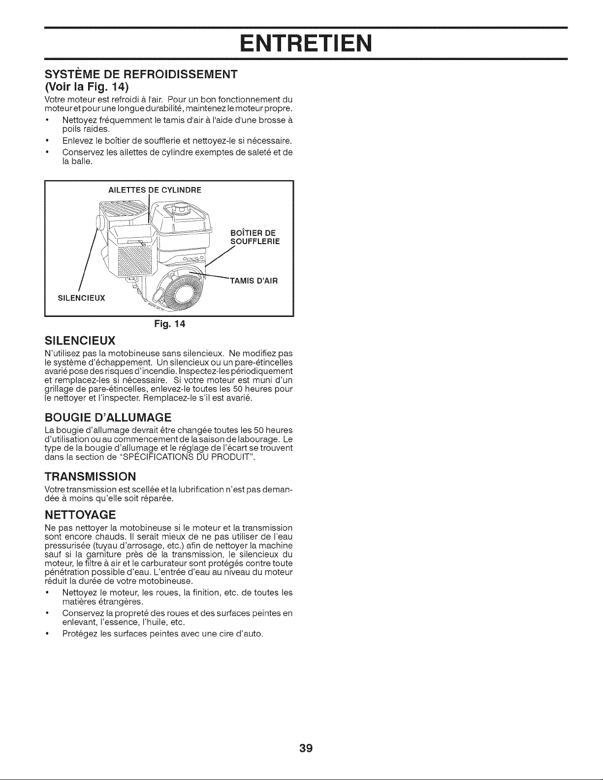
TRETI
SYSTI=ME DE REFROIDISSEiViENT
(Voir la Fig. 14)
Votre moteur est refroidi & Fair. Pour un bon fonctionnement du
moteur et pour une Iongue durabilit6, maintenez le moteur propre.
• Nettoyez fr6quemment le tamis d'air & I'aide d'une brosse
poils raides.
• Enlevez le bottler de souffterie et nettoyez-le si n6cessaire.
• Conservez les ailettes de cylindre exemptes de satet_ et de
la batle.
AILETTES DE CYLINDRE
BOITIER DE
SOUFFLERIE
SILENClEUX
D'AIR
Fig. 14
SILENCIEUX
N'utitisez pas la motobineuse sans silencieux. Ne modifiez pas
le syst6me d'6chappement. Un silencieux ou un pare-_tincelles
avari6 pose des risques d'incendie. Inspectez-tes p@iodiquement
et remplacez-les si n6cessaire. Si votre moteur est muni d'un
grillage de pare-6tincelles, enlevez-le toutes les 50 heures pour
le nettoyer et I'inspecter. Remplacez-te s'il est avari_.
BOUGIE D'ALLUMAGE
La bougie d'allumage devrait @re chang6e toutes les 50 heures
d'utilisation ou au commencement de la saison de tabourage. Le
type de la bougie d'atlumage et le r6glage de I'ecart se trouvent
dans la section de "SPECIFICATIONS DU PRODUIT".
TRANSMISSION
Votre transmission est scell6e et ta tubrification n'est pas deman-
d_e & moins qu'elle soit r_par_e.
NETTOYAGE
Ne pas nettoyer la motobineuse si le moteur et la transmission
sont encore chauds. I1serait mieux de ne pas utiliser de I'eau
pressurisee (tuyau d'arrosage, etc.) afin de nettoyer la machine
sauf si la garniture pros de la transmission, le silencieux du
moteur, le filtre & air et le carburateur sont prot6g_s contre toute
pen6tration possible d'eau. L'entr6e d'eau au niveau du moteur
r_duit la dur6e de votre motobineuse.
• Nettoyez le moteur, les roues, la finition, etc. de toutes les
mati@es 6trang@es.
• Conservez ta propret6 des roues et des surfaces peintes en
enlevant, I'essence, I'huile, etc.
• Prot_gez les surfaces peintes avec une cire d'auto.
39
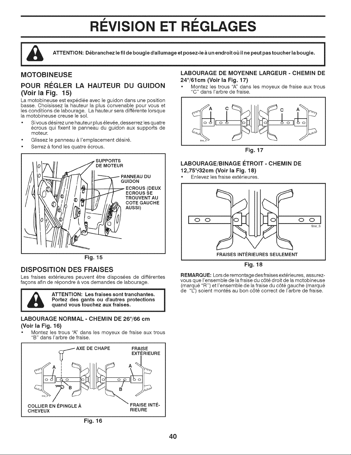
f
ET LAG
NIOTOBINEUSE
POUR RI_GLER LA HAUTEUR DU GUIDON
(Voir la Fig. 15)
La motobineuse est expedi6e avec le guidon dans une position
basse. Choisissez la hauteur la plus convenable pour vous et
les conditions de labourage. La hauteur sera diff_rente Iorsque
la motobineuse creuse le sot.
• Sivous d_sirez une hauteur ptus 6levee, desserrez les quatre
6crous qui fixent le panneau du guidon aux supports de
moteur.
• Glissez le panneau & I'emplacement d_sir&
Serrez & fond les quatre _crous.
LABOURAGE DE MOYENNE LARGEUR = CHEMIN DE
24"/61cm (Voir la Fig. 17)
• Montez les trous "A" dans les moyeux de fraise aux trous
"C" dans I'arbre de fraise.
Fig. 17
|
SUPPORTS
DE MOTEUR
I /_ _¢-..-_PANNEAUDU
_ GUIDON
_ECROUS(DEUX
"_ECROUSSE
/TROUVENTAU
k._COTE GAUCHE
,i_ Auss0
J
Fig. 15
DISPOSITION DES FRAISES
Les fraises ext_rieures peuvent _tre disposees de diff_rentes
fa£_onsafin de r_pondre & vos demandes de labourage.
Portez des gants ou d'autres protections |
I quand vous touchez aux fraises.
LABOURAGE NORMAL = CHEMIN DE 26"/66 cm
(Volt la Fig. 16)
• Montez les trous ",_' dans les moyeux de fraise aux trous
"B" dans I'arbre de fraise.
LABOURAGE/BINAGE F:TROIT - CHEMIN DE
12,75"_32cm (Volt la Fig. 18)
• Enlevez les fraise ext_rieures.
_ ]
Oll IIC o o
_ r _ tine 6
FRAISES INT[=RIEURESSEULEMENT
O O
Fig. 18
REMARQU E: Lors de remontage des fraises exterieures, assurez-
vous que I'ensemble de la fraise du c6t6 droit de la motobineuse
(marqu_ "R") et t'ensembte de la fraise du c6t6 gauche (marqu_
de "E') soient months au bon c6t_ correct de I'arbre de fraise.
.--AXE DE CHAPE FRAISE
EXT(=RIEURE
_71 ine A '__A_" B ° ,
FRAISE INTL=
COLLIER EN EPINGLE A
CHEVEUX RIEURE
Fig. 16
40
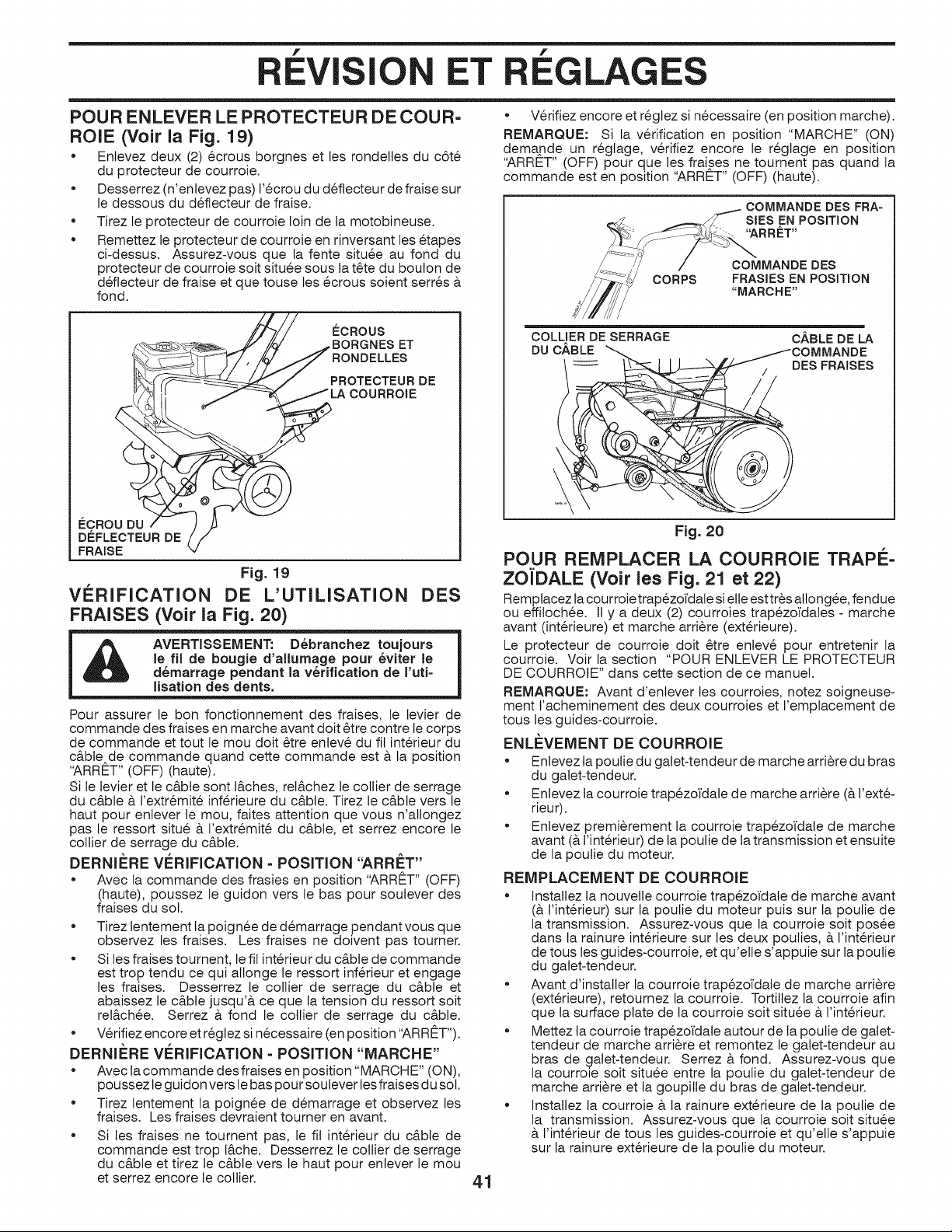
f
ET
f
LAG
POUR ENLEVER LE PROTECTEUR DE COUR-
ROlE (Volt la Fig. 19)
• Enlevez deux (2) 6crous borgnes et les rondetles du c6t_
du protecteur de courroie.
• Desserrez (n'enlevez pas) 1'6crou du d_flecteur de fraise sur
le dessous du d_flecteur de fraise.
• Tirez le protecteur de courroie loin de la motobineuse.
• Remettez le protecteur de courroie en rinversant les _tapes
ci-dessus. Assurez-vous que la fente situ6e au fond du
protecteur de courroie soit situ_e sous la t@e du boulon de
d_ftecteur de fraise et que touse les _crous soient serr_s &
fond.
¢CROU DU
D#FLECTEUR DE
FRAISE
ECROUS
BORGNES ET
RONDELLES
PROTECTEUR DE
_/1._ COURROIE
Fig. 19
VERIFICATION DE L'UTILISATION DES
FRAISES (Voir la Fig. 20)
AVERTISSEMENT: D6branchez toujours
le fiJ de bougie d'allurnage pour 6viter le
d6rnarrage pendant la v6rification de I'uti=
lisation des dents.
Pour assurer le bon fonctionnement des fraises, le levier de
commande des fraises en marche avant dolt @re contre le corps
de commande et tout le mou dolt @re entev6 du fil int@ieur du
c&ble de commande quand cette commande est a la position
"ARRET" (OFF) (haute).
Si le levier et le c&ble sont I&ches, rel&chez le collier de serrage
du c&ble a I'extr6mit6 inf@ieure du c&ble. Tirez le c&bte vers le
haut pour enlever le mou, fakes attention que vous n'attongez
pas le ressort situ_ a I'extr6mit_ du c&ble, et serrez encore le
collier de serrage du c&ble.
DERNIi_RE VI=RIFICATION - POSITION "ARRET"
• Avec la commande des frasies en position "ARRET" (OFF)
(haute), poussez le guidon vers le bas pour soulever des
fraises du sot.
• Tirez lentement la poign6e de d6marrage pendant vous que
observez les fraises. Les fraises ne doivent pas tourner.
• Si les fraises tournent, le fil int@ieur du c&ble de commande
est trop tendu ce qui attonge le ressort inf@ieur et engage
les fraises. Desserrez le collier de serrage du c&ble et
abaissez le c&ble jusqu'a ce que la tension du ressort soit
rel&ch6e. Serrez a fond le collier de serrage du c&ble.
• V@ifiez encore et r6glez si necessaire (en position "ARRET").
DERNIi_RE VERIFICATION - POSITION "MARCHE"
• Avec la commande des fraises en position "MARCH E" (ON),
poussez le guidon vers le bas pour soulever les fraises du sot.
• Tirez lentement la poign6e de d_marrage et observez les
fraises. Les fraises devraient tourner en avant.
• Si les fraises ne tournent pas, le fil int@ieur du c&ble de
commande est trop I&che. Desserrez le collier de serrage
du c&bte et tirez le c&ble vers le haut pour enlever le mou
et serrez encore le collier.
• V@ifiez encore et r6glez si n6cessaire (en position marche).
REMARQUE: Si la v@ification en position "MARCHE" (ON)
demande un r6gtage, v@ifiez encore le r6glage en position
"ARRET" (OFF) pour que les fraises ne tournent pas quand la
commande est en position "ARRET" (OFF) (haute).
COMMANDE DES FRA-
SIES EN POSITION
"ARRET"
CORPS
COMMANDE DES
FRASIES EN POSITION
"MARCHE"
COLLIER DE SERRAGE
DU C.&BLE
CABLE DE LA
DES FRAISES
Fig. 20
POUR REMPLACER LA COURROIE TRAPE-
ZOJ'DALE (Volt les Fig. 21 et 22)
Remplacez la courroie trap6zoi'dale si erie est tr_s allong6e, fendue
ou effilochee. It y a deux (2) courroies trapezoi'dales - marche
avant (int@ieure) et marche arri_re (ext@ieure).
Le protecteur de courroie dolt @re enlev_ pour entretenir la
courroie. Voir la section "POUR ENLEVER LE PROTECTEUR
DE COURROIE" darts cette section de ce manuel.
REMARQUE: Avant d'enlever les courroies, notez soigneuse-
ment t'acheminement des deux courroies et I'emptacement de
tousles guides-courroie.
ENLEVEMENT DE COURROIE
• Enlevez la poutie du gatet-tendeur de marche arri@e du bras
du galet-tendeur.
• Enlevez ta courroie trap_zoi'date de marche arri@e (& l'ext_-
rieur).
• Enlevez premi@ement la courroie trapezoi'dale de marche
avant (& t'int@ieur) de la poulie de la transmission et ensuite
de la poulie du moteur.
REMPLACEMENT DE COURROIE
• Instatlez la nouvetle courroie trapezoi'date de marche avant
(& I'int@ieur) sur la poutie du moteur puis sur la poulie de
la transmission. Assurez-vous que la courroie soit posse
darts la rainure int@ieure sur les deux pouties, & l'int@ieur
de tous les guides-courroie, et qu'elle s'appuie sur la poulie
du gatet-tendeur.
• Avant d'installer la courroie trapezoi'date de marche arri@e
(ext@ieure), retournez la courroie. Tortiltez la courroie afin
que la surface plate de la courroie soit situ_e & l'int@ieur.
• Mettez la courroie trapezoi'dale autour de la poutie de galet-
tendeur de marche arri@e et remontez le gatet-tendeur au
bras de galet-tendeur. Serrez & fond. Assurez-vous que
la courroie soit situ_e entre la poulie du gatet-tendeur de
marche arri_re et la goupille du bras de galet-tendeur.
• Instattez la courroie & la rainure ext@ieure de ta poulie de
la transmission. Assurez-vous que la courroie soit situ_e
& l'int@ieur de tousles guides-courroie et qu'elle s'appuie
sur la rainure ext@ieure de la poulie du moteur.
41
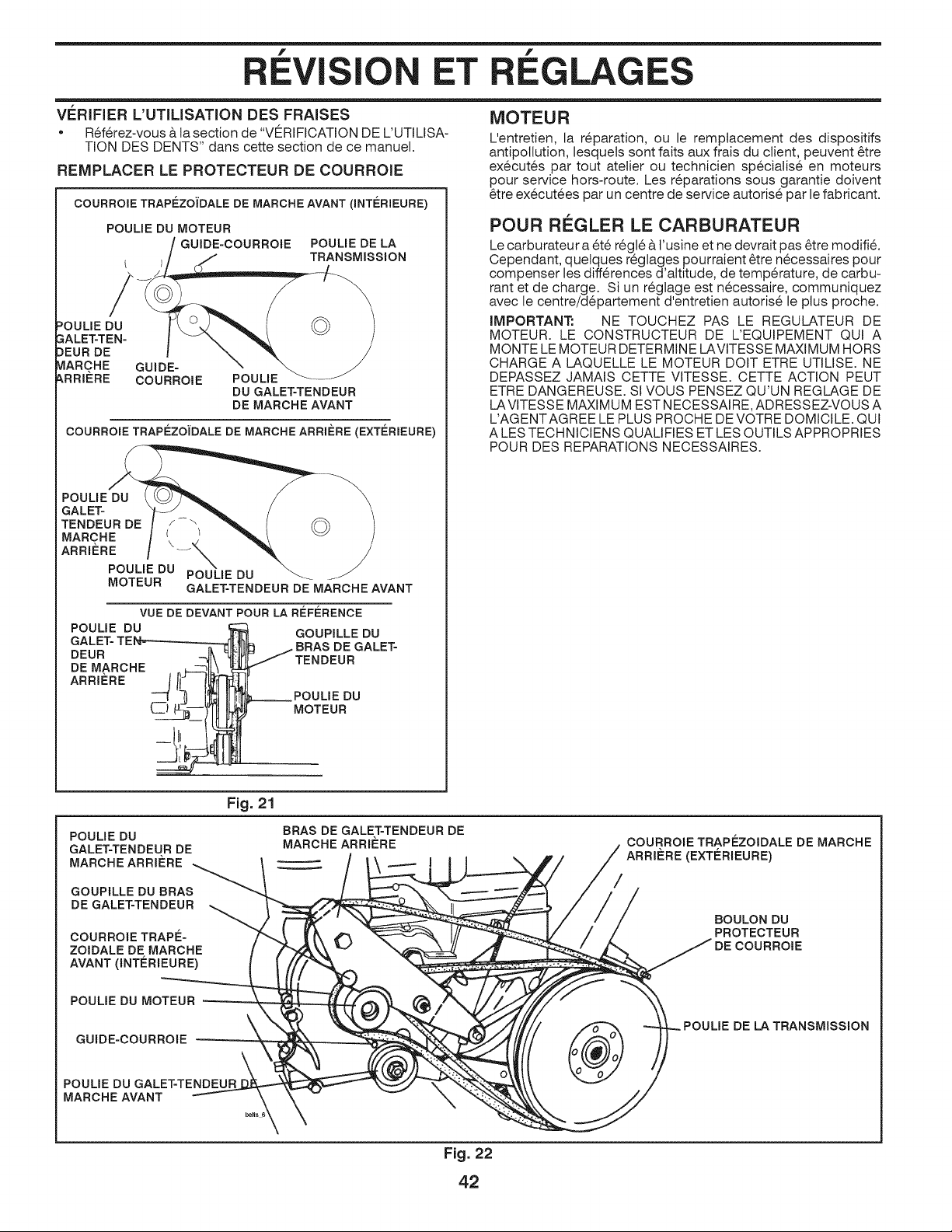
f
I ET
LAGES
VI_RIFIER L'UTILISATION DES FRAISES
• R6f@ez-vous & ta section de "VERIFICATION DE L'UTILISA-
TION DES DENTS" dans cette section de ce manuel.
REMPLACER LE PROTECTEUR DE COURROIE
COURROIE TRAPEZOi'DALE DE MARCHE AVANT (INT_:RIEURE)
POULIE DU MOTEUR
GUIDE-COURROIE POULIE DE LA
TRANSMISSION
POULIE DU
GALET=TEN=
DEUR DE
MARCHE GUIDE=
_,RRI_=RE COURROIE
POULIE
DU GALE_TENDEUR
DE MARCHEAVANT
COURROIE TRAPEZOIDALE DE MARCHE ARRIERE (EXTERIEURE)
POULIE DU
GALE%
TENDEUR DE /-\
MARCHE _
ARRIERE \%_UL
POULIE DU IE DU
MOTEUR
GALET=TENDEUR DE MARCHEAVANT
VUE DE DEVANTPOUR LA REFERENCE
POULIE DU GOUPILLEDU
GALE% BRAS DE GALE%
DEUR
DE MARCHE
ARRIERE
!
d POULIE DU
(_] MOTEUR
MOTEUR
L'entretien, la r_paration, ou le remplacement des dispositifs
antipotlution, lesquets sont faits aux frais du client, peuvent @re
execut6s par tout atelier ou technicien speciatis6 en moteurs
pour service hors-route. Les r6parations sous garantie doivent
@re ex6cut_es par un centre de service autoris_ par le fabricant.
POUR REGLER LE CARBURATEUR
Le carburateur a 6t6 r6g16& t'usine et ne devrait pas @re modifi_.
Cependant, quelques r6glages pourraient @re n6cessaires pour
compenser les diff@ences d'altitude, de temp@ature, de carbu-
rant et de charge. Si un r6glage est necessaire, communiquez
avec le centre/d_partement d'entretien autoris6 le plus proche.
IMPORTANT: NE TOUCHEZ PAS LE REGULATEUR DE
MOTEUR. LE CONSTRUCTEUR DE L'EQUIPEMENT QUI A
MONTE LE MOTEUR DETERMINE LAVITESSE MAXIMUM HORS
CHARGE A LAQUELLE LE MOTEUR DOlT ETRE UTILISE. NE
DEPASSEZ JAMAIS CETTE VITESSE. CETTE ACTION PEUT
ETRE DANGEREUSE. Sl VOUS PENSEZ QU'UN REGLAGE DE
LAVITESSE MAXIMUM EST NECESSAIRE, ADRESSEZ-VOUS A
L'AGENTAGREE LE PLUS PROCHE DE VOTRE DOMICILE. QUI
ALES TECHNICIENS QUALIFIES ET LES OUTILS APPROPRIES
POUR DES REPARATIONS NECESSAIRES.
POULIE DU
GALE%TENDEUR DE
MARCHEARRIERE
GOUPILLE DU BRAS
DE GALE%TENDEUR
COURROIE TRAP¢ _=
ZOIDALE DE MARCHE
AVANT (INT_=RIEURE)
POULIE DU MOTEUR
GUIDE=COURROIE
Fig. 21
POULIE DU GALE%TENDEUR
MARCHE AVANT
BRAS DE GALE%TENDEUR DE
MARCHEARRIERE
d OURROIE TRAPEZOIDALE DE MARCHE
ARRIL=RE(EXTL=RIEURE)
IE DE LATRANSMISSION
Fig. 22
42
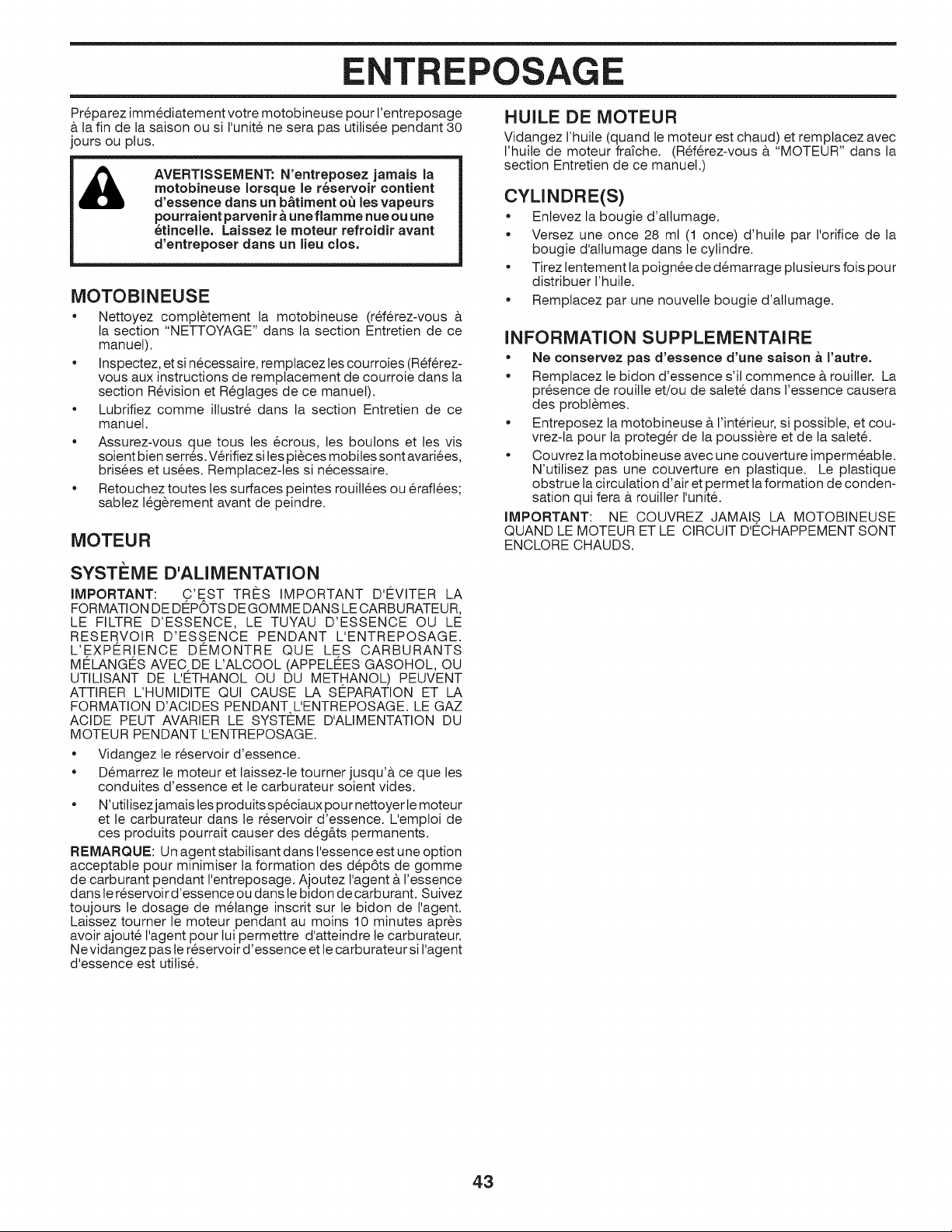
POSAGE
Preparez immediatement votre motobineuse pour I'entreposage
& la fin de la saison ou si I'unit_ ne sera pas utilis_e pendant 30
jours ou plus.
AVERTISSEMENT: N'entreposez jamais la
rnotobineuse Iorsque le r_servoir contient
d'essence dans un b&timent o_ les vapeurs
pourraient parvenir a une flarnrne hue ou une
_tincelle. Laissez le rnoteur refroidir avant
d'entreposer dans un lieu clos.
MOTOBINEUSE
• Nettoyez compl_tement la motobineuse (r_f@ez-vous &
la section "NETTOYAGE" dans la section Entretien de ce
manuel).
• Inspectez, et si n6cessaire, remptacez les courroies (R_f@ez-
vous aux instructions de remptacement de courroie dans la
section R6vision et R6glages de ce manuel).
• Lubrifiez comme illustr_ dans la section Entretien de ce
manuel.
• Assurez-vous que tous les 6crous, les boutons et les vis
soient bien serr6s. V@ifiez sites pi_ces mobiles sont avarices,
bris6es et us6es. Remplacez-tes si n6cessaire.
• Retouchez toutes tes surfaces peintes rouitl_es ou @aft_es;
sabtez l_g_rement avant de peindre.
MOTEUR
SYSTI_ME D'AUMENTATION
iMPORTANT: C'EST TRES iMPORTANT D'EVITER LA
FORMATION DE DEPOTS DE GOMME DANS LE CARBURATEUR,
LE FILTRE D'ESSENCE, LE TUYAU D'ESSENCE OU LE
RESERVOIR D'ESSENCE PENDANT L'ENTREPOSAGE.
L'EXPERIENCE DEMONTRE QUE LES CARBURANTS
MELANGES AVEC DE L'ALCOOL (APPELEES GASOHOL, OU
UTILISANT DE L'ETHANOL OU DU METHANOL) PEUVENT
ATTIRER L'HUMIDITE QUI CAUSE LA SEPARATION ET LA
FORMATION D'ACIDES PENDANT L'ENTREPOSAGE. LE GAZ
ACIDE PEUT AVARIER LE SYSTEME D'ALIMENTATION DU
MOTEUR PENDANT L'ENTREPOSAGE.
• Vidangez le r6servoir d'essence.
• D6marrez le moteur et laissez-le tourner jusqu'& ce que les
conduites d'essence et le carburateur soient vides.
• N'utilisez jamais les produits speciaux pour nettoyer le moteur
et le carburateur dans le r6servoir d'essence. L'emptoi de
ces produits pourrait causer des d_g&ts permanents.
REMARQUE: Un agent stabilisant darts I'essence est une option
acceptable pour minimiser la formation des d_p6ts de gomme
de carburant pendant I'entreposage. Ajoutez I'agent & l'essence
dans te r6servoir d'essence ou darts te bidon de carburant. Suivez
toujours le dosage de m_lange inscrit sur le bidon de I'agent.
Laissez tourner le moteur pendant au moins 10 minutes apr6s
avoir ajout6 I'agent pour lui permettre d'atteindre le carburateur.
N evidangez paste r6servoir d'essence et te carburateur si I'agent
d'essence est utilis_.
HUILE DE MOTEUR
Vidangez l'huite (quand le moteur est chaud) et remptacez avec
I'huile de moteur frafche. (Ref@ez-vous & "MOTEUR" dans la
section Entretien de ce manuel.)
CYLINDRE(S)
• Enlevez la bougie d'attumage.
• Versez une once 28 mt (1 once) d'huile par I'orifice de la
bougie d'allumage dans le cylindre.
• Tirez lentement la poign_e de d_marrage plusieurs fois pour
distribuer I'huile.
• Remplacez par une nouvelle bougie d'atlumage.
INFORMATION SUPPLEMENTAIRE
• Ne conservez pas d'essence d'une saison _ I'autre.
• Remplacez le bidon d'essence s'it commence & rouiller. La
pr6sence de rouille et/ou de satet_ dans l'essence causera
des probl_mes.
• Entreposez la motobineuse & l'int@ieur, si possible, et cou-
vrez-ta pour la proteg@ de la poussi_re et de la satet6.
• Couvrez ta motobineuse avec une couverture imperm6abte.
N'utilisez pas une couverture en ptastique. Le ptastique
obstrue la circulation d'air et permet la formation de conden-
sation qui fera & rouitler I'unit_.
IMPORTANT: NE COUVREZ JAMAIS LA MOTOBINEUSE
QUAND LE MOTEUR ET LE CIRCUIT D'ECHAPPEMENT SONT
ENCLORE CHAUDS.
43
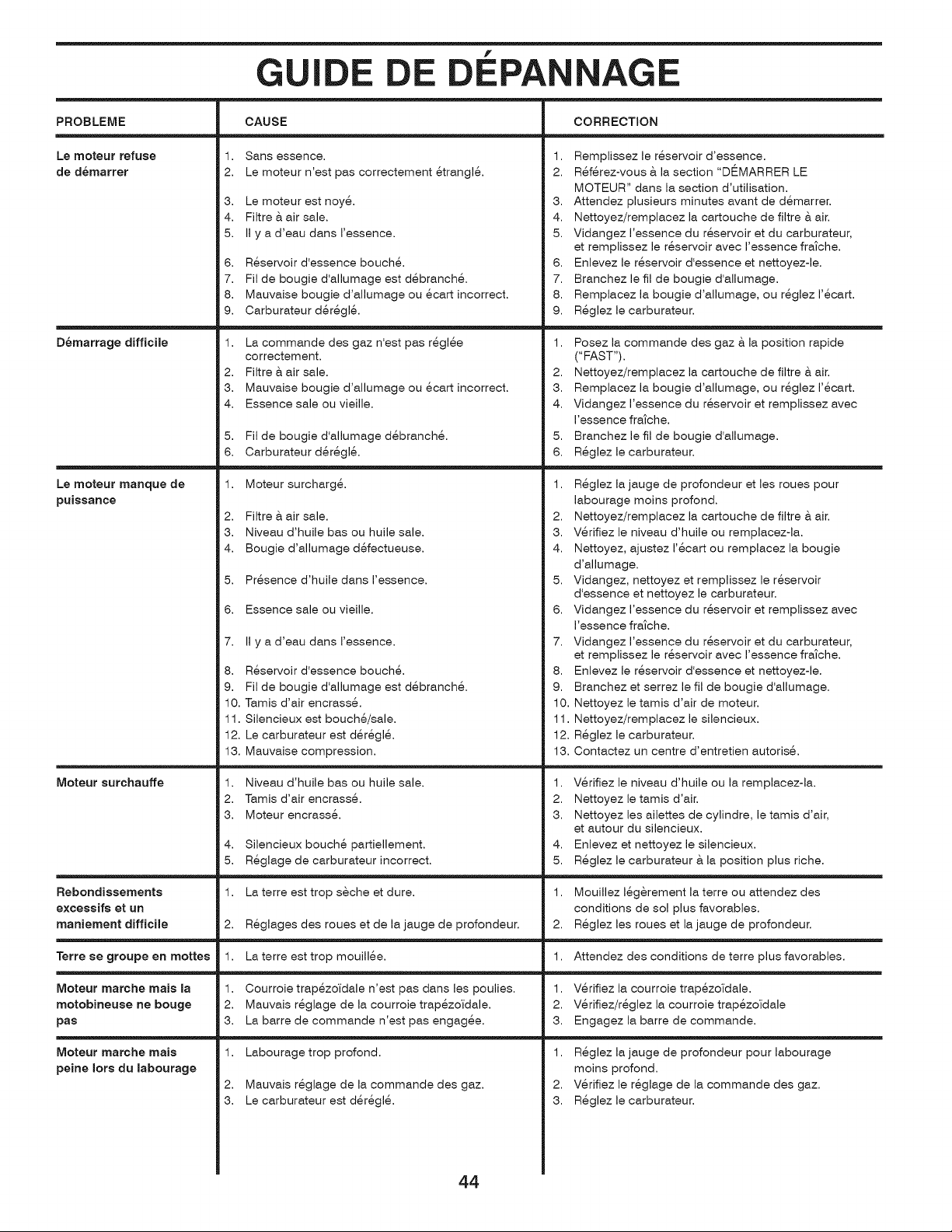
f
G I E
CAUSE CORRECTIONPROBLEME
Le moteur refuse
de demarrer
Demarrage difficile
Le moteur manque de
puissance
Moteur surchauffe
1. Sans essence.
2. Le moteur n'est pas correctement 6trangl&
3. Le moteur est noy&
4. Filtre & air sale.
5. II y a d'eau dans I'essence.
6. R_servoir d'essence bouch&
7. Fil de bougie d'allumage est d_branch_.
8. Mauvaise bougie d'allumage ou 6cart incorrect.
9. Carburateur d6r6g16.
1. La commande des gaz n'est pas r6gl6e
correctement.
2. Filtre & air sale.
3. Mauvaise bougie d'allumage ou 6cart incorrect.
4. Essence sale ou vieille.
5. Fil de bougie d'allumage d6branch&
6. Carburateur d6r6g16.
1. Moteur surcharg&
2. Filtre & air sale.
3. Niveau d'huile bas ou huile sale.
4. Bougie d'allumage d6fectueuse.
5. Pr6sence d'huile dans I'essence.
6. Essence sale ou vieille.
1. Remplissez le r6servoir d'essence.
2. R6f6rez-vous & la section "DI_MARRER LE
MOTEUR" dans la section d'utilisation.
3. Attendez plusieurs minutes avant de d_marrer.
4. Nettoyez/remplacez la cartouche de filtre & air.
5. Vidangez I'essence du r6servoir et du carburateur,
et remplissez le r6servoir avec I'essence fra_che.
6. Enlevez le r6servoir d'essence et nettoyez-le.
7. Branchez le fil de bougie d'allumage.
8. Remplacez la bougie d'allumage, ou r6glez 1'6cart.
9. R_glez le carburateur.
1. Posez la commande des gaz & la position rapide
("FAST").
2. Nettoyez/remplacez la cartouche de filtre & air.
3. Remplacez la bougie d'allumage, ou r_glez I'_cart.
4. Vidangez I'essence du r_servoir et remplissez avec
I'essence fratche.
5. Branchez le fil de bougie d'allumage.
6. R_glez le carburateur.
1. R_glez la jauge de profondeur et les roues pour
labourage moins profond.
2. Nettoyez/remplacez la cartouche de filtre & air.
3. V_rifiez le niveau d'huile ou remplacez-la.
4. Nettoyez, ajustez I'_cart ou remplacez la bougie
d'allumage.
5. Vidangez, nettoyez et remplissez le r_servoir
d'essence et nettoyez le carburateur.
6. Vidangez I'essence du r_servoir et remplissez avec
I'essence fratche.
7. Vidangez I'essence du r_servoir et du carburateur,
et remplissez le r_servoir avec I'essence fra_che.
8. Enlevez le r_servoir d'essence et nettoyez-le.
9. Branchez et serrez le fil de bougie d'allumage.
10. Nettoyez le tamis d'air de moteur.
11. Nettoyez/remplacez le silencieux.
12. R_glez le carburateur.
13. Contactez un centre d'entretien autoris_.
7. II y a d'eau dans I'essence.
8. R_servoir d'essence bouch&
9. Fil de bougie d'allumage est d_branch_.
10. Tamis d'air encrass&
11. Silencieux est bouch6/sale.
12. Le carburateur est d_r6gl6.
13. Mauvaise compression.
1. Niveau d'huile bas ou huile sale.
2. Tamis d'air encrass&
3. Moteur encrass&
Silencieux bouch6 partiellement.
R_glage de carburateur incorrect.
La terre est trop seche et dure.
R_glages des roues et de la jauge de profondeur.
La terre est trop mouill6e.
Courroie trap6zoldale n'est pas dans les poulies.
Mauvais r6glage de la courroie trap6zoldale.
La barre de commande n'est pas engag_e.
Labourage trop profond.
2. Mauvais r6glage de la commande des gaz.
3. Le carburateur est d6r6g16.
1.
2.
3.
V6rifiez le niveau d'huile ou la remplacez-la.
Nettoyez le tamis d'air.
Nettoyez les ailettes de cylindre, le tamis d'air,
et autour du silencieux.
Enlevez et nettoyez le silencieux.
R_glez le carburateur & la position plus riche.
4, 4,
5. 5.
Rebondissements 1. 1. Mouillez 16gerement la terre ou attendez des
excessifs et un conditions de sol plus favorables.
maniement difficile 2. 2. R_glez les roues et la jauge de profondeur.
Terre se groupe en mottes 1. 1. Attendez des conditions de terre plus favorables.
Moteur marche mais la 1. 1. V_rifiez la courroie trap6zoldale.
motobineuse ne bouge 2. 2. V6rifiez/r6glez la courroie trap6zoldale
pas 3. 3. Engagez la barre de commande.
Moteur marche mais 1.
peine Iors du labourage
1. R6glez la jauge de profondeur pour labourage
moins profond.
2. V6rifiez le r6glage de la commande des gaz.
3. R_glez le carburateur.
44
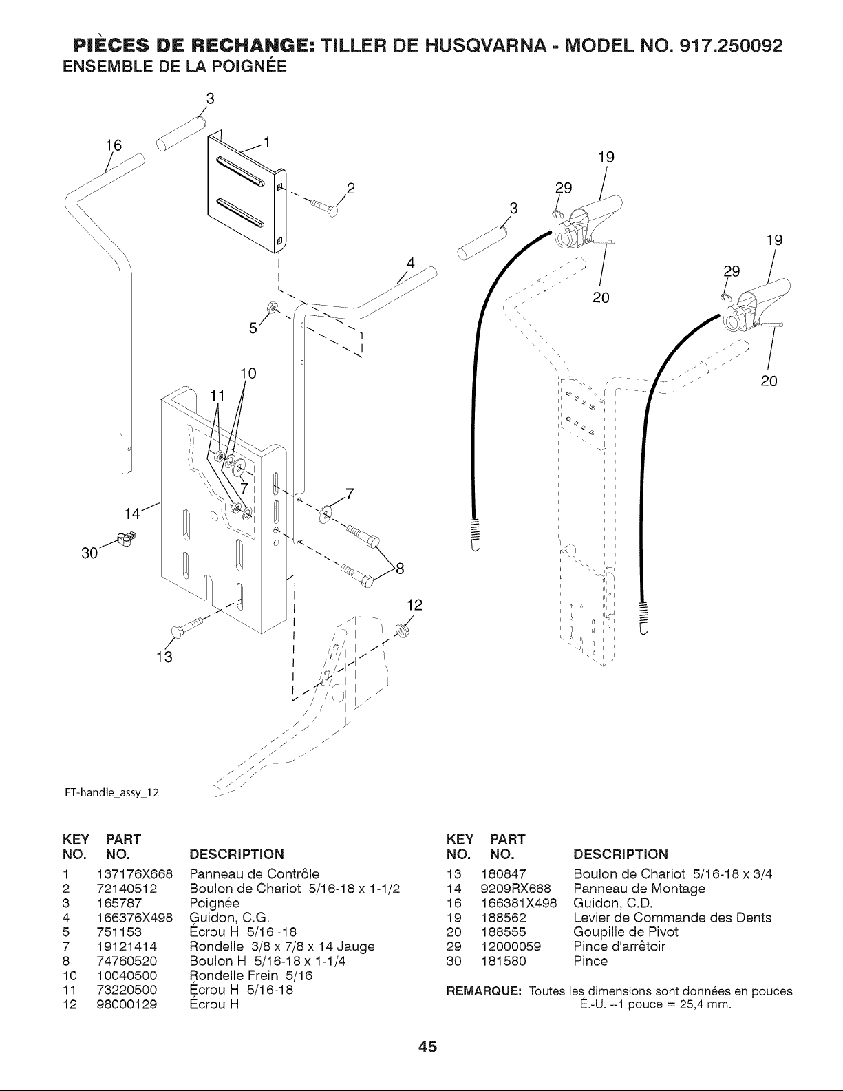
PIECES DE RECHANGE: TILLER DE HUSQVARNA- MODEL NO, 917.250092
ENSEMBLE DE LA POIGNEE
16
2
1
30_
FT-handle_assy_l 2
10
13
I
I
c.
12
I j
l
i I
C
19
KEY PART
NO. NO.
1 137176X668
2 72140512
3 165787
4 166376X498
5 751153
7 19121414
8 74760520
10 10040500
11 73220500
12 98000129
DESCRIPTION
Panneau de Contr61e
Boulon de Chariot 5/16-18 x 1-1/2
Poignee
Guidon, C.G.
Ecrou H 5/16 -18
Rondelle 3/8 x 7/8 x 14 Jauge
Boulon H 5/16-18x 1-1/4
Rondelle Frein 5/16
Ecrou H 5/16-18
E_crouH
KEY PART
NO. NO. DESCRIPTION
13 180847 Boulon de Chariot 5/16-18 x 3/4
14 9209RX668 Panneau de Montage
16 166381X498 Guidon, C.D.
19 188562 Levier de Commande des Dents
20 188555 Goupille de Pivot
29 12000059 Pince d'arr6toir
30 181580 Pince
REMARQUE: Toutes les dimensions sont donn_es en pouces
E.-U. --1 pouce = 25,4 mm.
45
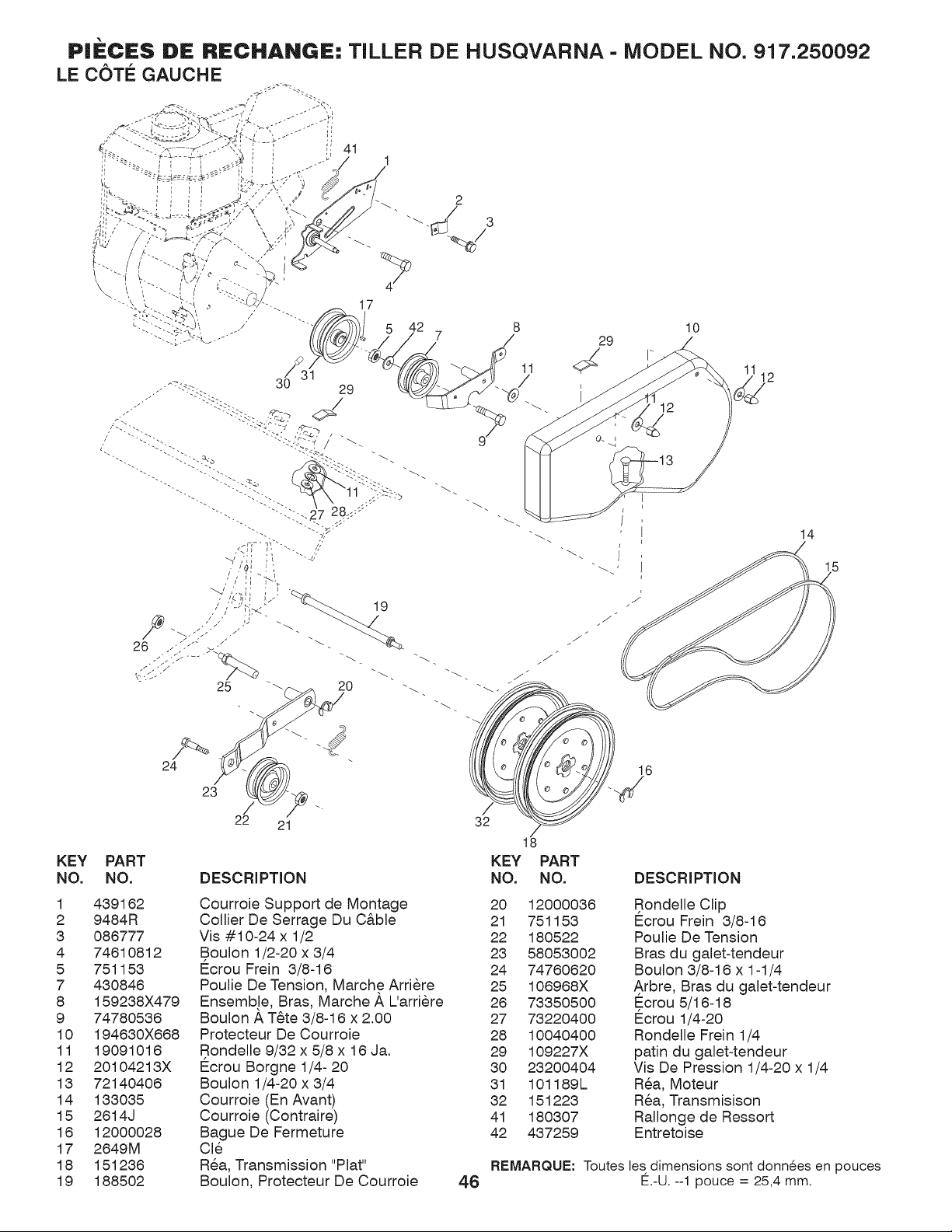
29
11 4_ I"
/ 12
./
14
KEY
NO.
PART
NO.
24
23
/
22 21
DESCRIPTION
16
32
KEY PART
NO. NO. DESCRIPTION
1
2
3
4
5
7
8
9
10
11
12
13
14
15
16
17
18
19
439162
9484R
086777
74610812
751153
430846
159238X479
74780536
194630X668
19091016
20104213X
72140406
133035
2614J
12000028
2649M
151236
188502
Courroie Support de Montage
Collier De Serrage Du C&ble
Vis #10-24 x 1/2
Boulon 1/2-20 x 3/4
E_crou Frein 3/8-16
Poulie De Tension, Marche Arriere
Ensemb!e, Bras, Marche _, L'arriere
Boulon A T6te 3/8-16 x 2.00
Protecteur De Courroie
Rondelle 9/32 x 5/8 x 16 Ja.
E_crou Borgne 1/4- 20
Boulon 1/4-20 x 3/4
Courroie (En Avant)
Courroie (Contraire)
Bague De Fermeture
Cle
Rea, Transmission "Plat"
Boulon, Protecteur De Courroie
20 12000036 Rondelle Clip
21 751153 E_crou Frein 3/8-16
22 180522 Poulie De Tension
23 58053002 Bras du galet-tendeur
24 74760620 Boulon 3/8-16 x 1-1/4
25 106968X A rbre, Bras du galet-tendeur
26 73350500 Ecrou 5/16-18
27 73220400 Ecrou 1/4-20
28 10040400 Rondelle Frein 1/4
29 109227X patin du galet-tendeur
30 23200404 Vis De Pression 1/4-20 x 1/4
31 101189L Rea, Moteur
32 151223 Rea, Transmisison
41 180307 Rallonge de Ressort
42 437259 Entretoise
REMARQUE: Toutes les dimensions sont donnees en pouces
4.6 E.-U. --1 pouce = 25,4 mm.
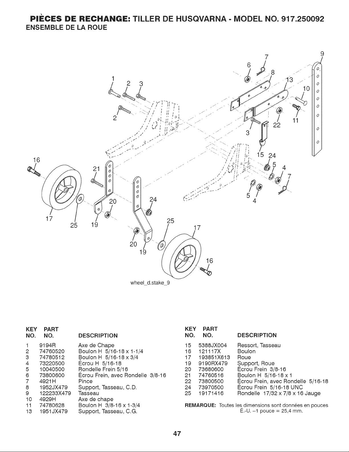
P|IECIES DE RECHANGIE: TILLER DE HUSQVARNA- MODEL NO, 917.250092
ENSEMBLE DE LA ROUE
16
17
21
25 19
6
20
wheel d.stake 9
25
15
17
KEY
NO.
1
2
3
4
5
6
7
8
9
10
11
13
PART
NO.
9194R
74760520
74780512
73220500
10040500
73800600
4921H
1952JX479
122233X479
4929H
74780628
1951JX479
DESCRIPTION
Axe de Chape
BoulonH 5/16-18x1-1/4
BoulonH 5/16-18x3/4
Ecrou H 5/16-18
Rondelle Frein 5/16
Ecrou Frein, avec Rondelle 3/8-16
Pince
Support, Tasseau, C.D.
Tasseau
Axe de chape
Boulon H 3/8-16 x 1-3/4
Support, Tasseau, C.G.
KEY PART
NO. NO. DESCRIPTION
15 5388JX004
16 121117X
17 193851X613
19 9190RX479
20 73680600
21 74760516
22 73800500
24 73970500
25 19171416
Ressort, Tasseau
Boulon
Roue
Support, Roue
Ecrou Frein 3/8-16
Boulon H 5/16-18 x 1
Ecrou Frein, avec Rondelle 5/16-18
Ecrou Frein 5/16-18 UNC
Rondelle 17/32 x 7/8 x 16 Jauge
REMARQUE: Toutes les dimensions sont donnees en pouces
E.-U. -1 pouce = 25,4 mm.
47
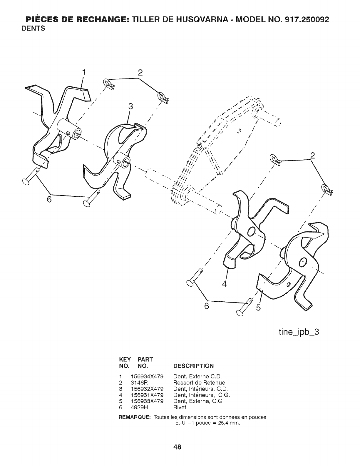
P|ECES DE RECHANGIE: TILLER DE HUSQVARNA- MODEL NO. 917.250092
DENTS
6
/
2
/
/
/
/
/
/
/
/
/
5
tJne_ipb_3
KEY PART
NO. NO. DESCRIPTION
1
2
3
4
5
6
156934X479
3146R
156932X479
156931X479
156933X479
4929H
Dent, Externe C.D.
Ressort de Retenue
Dent, Interieurs, C.D.
Dent, Interieurs, C.G.
Dent, Externe, C.G.
Rivet
REMARQUE: Toutes les dimensions sont donnees en pouces
E.-U. --1 pouce = 25,4 mm.
48
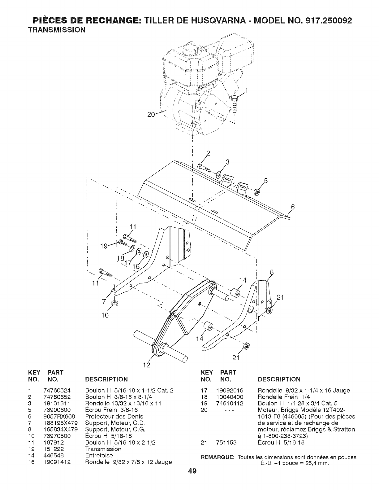
P|ECE$ DE RECHANGE" TILLER DE HUSQVARNA- MODEL NO, 917.250092
TRANSMiSSiON
2
/ 3
11
5
6
1
d8
11
10
14
21
KEY
NO.
1
2
3
5
6
7
8
10
11
12
14
16
PART
NO.
74760524
74780652
19131311
73900600
9057RX668
188195X479
165834X479
73970500
187912
151222
446548
19091412
12
DESCRIPTION
BoulonH 5/16-18 x1-1/2 Cat. 2
Boulon H 3/8-16 x 3-1/4
Rondelle 13/32 x 13/16 x 11
E_crouFrein 3/8-16
Protecteur des Dents
Support, Moteur, C.D.
Support, Moteur, C.G.
Ecrou H 5/16-18
BoulonH 5/16-18x2-1/2
Transmission
Entretoise
Rondelle 9/32 x 7/8 x 12 Jauge
21
KEY PART
NO. NO.
17 19092016
18 10040400
19 74610412
20 ---
21 751153
DESCRIPTION
Rondelle 9/32 x 1-1/4 x 16 Jauge
Rondelle Frein 1/4
Boulon H 1/4-28 x 3/4 Cat. 5
Moteur, Briggs Modele 12T402-
1613-F8 (446085) (Pour des pieces
de service et de rechange de
moteur, reclamez Briggs & Stratton
& 1-800-233-3723)
E_crou H 5/16-18
REMARQUE: Toutes les dimensions sont donn_es en pouces
E.-U. -1 pouce = 25,4 mm.
49
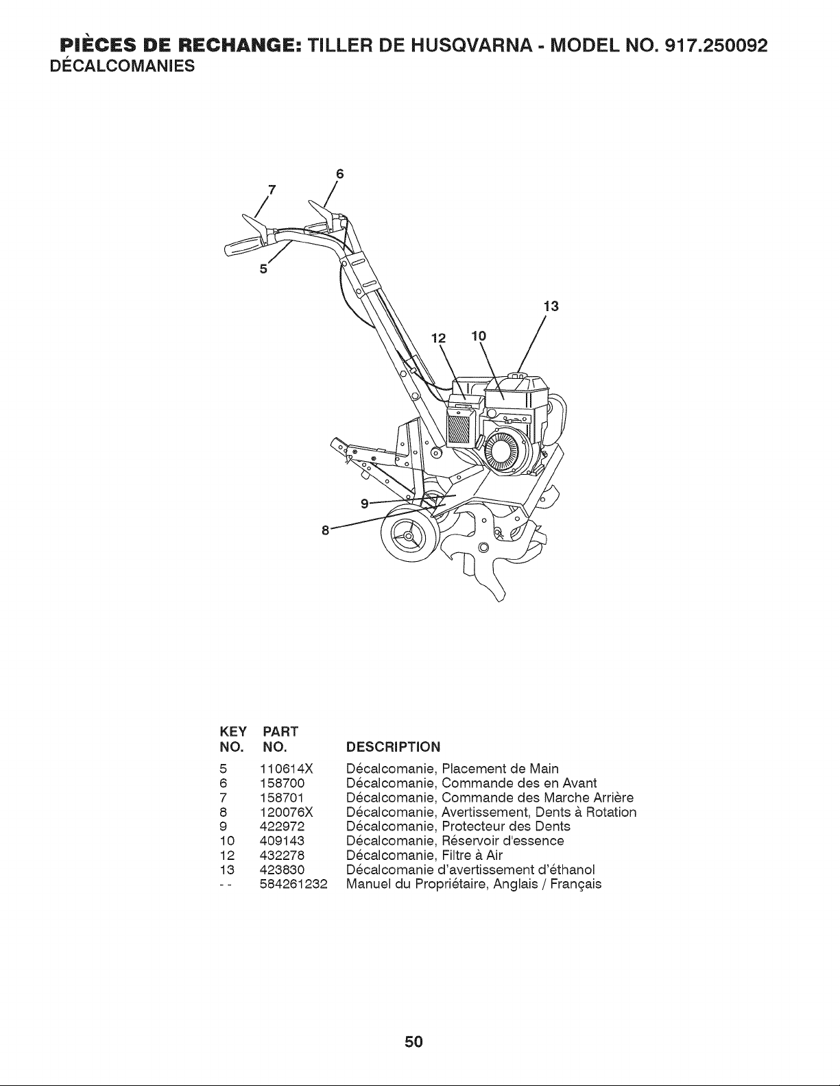
P|ECES DE RECHANGE: TILLER DE HUSQVARNA- MODEL NO. 917.250092
DECALCOMANIES
6
7
/
5
91
12
10
13
KEY
NO.
5
8
7
8
9
10
12
13
PART
NO.
110614X
158700
158701
120076X
422972
409143
432278
423830
584261232
DESCRiPTiON
Decalcomanie
Decalcomanie
Decalcomanie
Decalcomanie
Decalcomanie
Decalcomanie
Decalcomanie
Placement de Main
Commande des en Avant
Commande des Marche Arriere
Avertissement, Dents & Rotation
Protecteur des Dents
Reservoir d'essence
Filtre & Air
Decalcomanie d'avertissement d'ethanol
Manuel du Proprietaire, Anglais / Francais
5O
Husqvarna
Produits sur roues de consommateur - Garanfie |imit6e
Husqvama garantit il l'acheteur original que ce produit HusqvarnaMD est exempt de vices de mat6rlanx ou de fabrication sons des conditions normales d'utilisation
et d'entretien il compter de la date d'achat an ddtail pour la p&iode de garantie applicable indiqude il l'annexe A. Cette garantie ne pent _tre transfdrde il aucun aqudreur
subs&tuent de ce produit Husqvarna:R). Certains composants (p. ex. les moteurs et les transmissions) sont exclus de la couverture et d'autres restrictions s'appliquent
COl"hi'hele ddcrit ce document. Husqvarna r@arera ou remplacera il sa discrdtion, tout produit ou pi_ces ddfcctueux converts par la garantie limitde, gratuitement dans un
centre de service agrdd ou un d@ositaire Husqvarna en utilisant les pi_ces de remplacements d'origine Husqvarna, sons rdsela-e des restrictions et exclusions ci-dessous.
Husqvarna n'offi'e pas un programme d'dchange an comptoir.
AVERTISSEMENTS, LIMITATIONS ET EXCLI SIONS
1. EXCLI SION DE GARANTIE. CETTE GARANTIE LIMITt_E EST LA SEULE GARANTIE EXPRESSE FOURNIE PAR HUSQVARNA ET IL N'EXISTE PAS
D'AUTRES GARANTIES EXPRESSE A L'EXCEPTION DE CELLES QUI SONT EXPRESSt_MENT AU PRt_SENT DOCUMENT, SAUF SUIVANT LES LOIS
APPLICABLES. CETTE GARANTIE EST OFFERTE I NI(_)I EMENT PAR HUSQVARNA ET NE PEUT I_TRE MODIFIt_E QUE PAR HUSQVARNA. CETTE
GARANTIE LIMITt_E EST L'EXPRESSION FINALE DE NOTRE ACCORD, ET EXPRIME COMPLI_TEENT ET EXCLUSIVEMENT LES CONDITIONS
DE CET ACCORD. LA PRt_SENTE GARANTIE LIMITI_E VOUS DONNE DES DROITS SPt_CIFIQUES, ET VOUS POUVEZ AVOIR D'AUTRES DROITS
LESQUELS VARIENT SUIVANT VOTRE EMPLACEMENT.
2. Dt RI_E LIMITI_E. TOUTE GARANTIE POUVANT I_TRE IMPLICITE PAR LA LOI (Y COMPRIS TOUTE GARANTIE IMPLICITE DE CONVENANCE
UN USAGE PARTICULIER OU D'UTILISATION ET DE GARANTIE IMPLICITE DE QUALITE MARCHANDE) EST LIMITt_E A LA DURt_E DE LA
Pt_RIODE DE GARANTIE APPLICABLE EN VERTU DE CETTE GARANTIE. CERTAINES LOCALITIES N'AUTORISENT PAS LES LIMITATIONS SUR LA
DURt_E D'UNE GARANTIE IMPLICITE, LES LIMITATIONS CI-DESSOUS PEUVENT NE PAS S'APPLIQUER A VOUS.
3. RECOI RS EXCLUSIFS. CERTAINES LOCALITIES, Y COMPRIS LA PROVINCE DU QUt_BEC, NE PERMETTENT PAS L'EXCLUSION OU LA
LIMITATION DE GARANTIE POUR LES DOMMAGES CORPORELS OU POUR LES DOMMAGES Rt_SULTANTS D'UN Dt_FAUT DE FABRICATION, ET!
OU L'EXCLUSION OU LA LIMITATION SUR LES DOMMAGES INDIRECTS OU CONSt_CUTIFS. PAR CONSt_QUENT, CERTAINES DES LIMITATIONS CI-
DESSOUS PEUVENT NE PAS S'APPLIQUER A VOUS. LES RECOURS CI-DESSUS SONT LES SEULS RECOURS EXCLUSIFS POUR TOUTE VIOLATION
DE CETTE GARANTIE LIMITt_E. AUCUN AUTRE RECOURS, Y-COMPRIS MAIS SANS S'Y LIMITER, AUX DOMMAGES ACCESSOIRES, INDIRECTS
OU CONSt_CUTIFS, POUR UNE PERTE DE PROFITS, UNE PERTE DE VENTES, DES DOMMAGES CORPORELS OU MATt_RIELS, OU TOUT DOMMAGE
ACCESSOIRE OU CONSt_CUTIF, N'EST DISPONIBLE, ET TOUS LES DOMMAGES SONT EXCLUS PAR LA PRt_SENTE.
4. Les motenrs, transmissions et certains autres composants ne sont PAS converts.. Cette garantie limitde ne couw'e aucun des cas suivants :
(a9)/Ioteurs et accessoires.Saufautrenaent indiqud sur l'Annexe A, tons les moteurs et accessoires ne sont pas converts par cette garantie. Dans la plupart des cas,
ces articles ne sont PAS fabriquds par Husqvarna, auquel cas, ils peuvent _tre converts s@ardment par les garanties de leur fabricant respectif si elles sont fournies et
accompagnent le produit an moment de l'achat. Toutes les rdclamations doivent _tre somnises et envoydes an fabricant appropri6 ou selon toute autre indication sur ces
garanties distinctes. Husqvarna n'est pas autorisde il effcctuer des rdglages ou des r@arations sons garantie dons le cos des moteurs fabriquds par Briggs & Stratton,
Honda, Kawasaki ou Kohler (exception : modules &tuipds de moteurs LCT). Husqvarna n'assmne aucune obligation sons garantie dons le cos des moteurs d'autres
fabricants, sons cette garantie limitde.
(b) Transmissions. Sauf autrement indiqud il l'Annexe A, outes les transmissions / boites-pont(incluant les syst_mes d'entralnement) ne sont pas couvertes par cette
garantie limitde. Dans la plupart des cas, ces articles ne sont PAS fabriquds par Husqvarna, auquel cos, ils peuvent _tre converts s@ardment par les garanties de leur
fabricant respectif si elles sont fournies et accompagnent le produit an moment de l'achat. Les fabricants suivants de transmission / bolte-pont, Dana, Hydro-Geac
Tuff-Torq, offi'ent une garantie sur la transmission ou la boite-pont il l'acheteur final ou il Husqvarna. Husqvarna assignera par la suite la garantie du fabricant sur la
transmission / boite-pont, ou tout &oit il cet dgard, il l'acheteur original de l'appareil. Pour obtenir un service sons garantie au niveau de la transmission / boite-pont,
comnmniquer d'abord avec le ddtaillant aupr_s de qui l'appareil a dtd achet& Si vous oyez besoin d'aide ou si vous oyez des questions concernant la garantie en lien
avec la transmission / boite-pont, communiquer avec Husqvarna directement il partir du site Web www.husqvarna.com ou appelez le 800 487 5951 (t_.-U.) ou le
800 805 5523 (Canada) pour contacter un revendeur Husqvarna autoris& Toutes les rdclamations doivent _tl'e soumises et envoydes an fabricant approprid ou selon
toute autre indication sur ces garanties distinctes. Husqvarna n'est pas autorisde il effcctuer les rdglages ou les r@arations an titre de la garantie sur les transmissions ou
les boites-pont. Husqvarna n'assmne pas d'obligation de garantie il l'dgard des thbricants indiquds ci-haut (pour les exceptions vok l'Annexe A).
(c') Pi_,ces' twtT-r&itilis'ables'. Cette garantie limitde ne couvre pas les articles et pi_ces d'entretien gdndrales (<<Pi_ces non-rdutilisables >>), incluant, mais sans s'y
limiter, les bougies d'allumage, ampoules, filtres, lubrifiants, cordes de lanceur, courroies, lames et adaptateurs de lames..
(d) ComposazTts de cozTrr6le d'6missiozTs. Cette garantie limitde ne couvre pas l'&luipement et les composants de contr61e des dmissions au-deli_ des r_glements de
I'U.S. Environmental Protection Agency (EPA) ou autres agences semblables. Ces &tuipements et composants sont converts par une ddclaration de garantie de contr61e
des dmissions distincte, fore'hie avec votre nouveau produit. Vcuillez lire les in£\_rmations sur cette ddclaration de garantie distincte.
5. Toute utilisation COMMERCIALE, INSTITUTIONNELLE, AGRICOLE, A REVENU DE PRODUCTION ou LOCATIVE r6sultera soit
par une suppression de la garantie ou le raccourcissement de sa dur6e. Selon le produit, soit il ne b6n6ficiera d'aucune garantie ou sa dur6e sera
r6duite, si le produit est utilis6/_ des fins commerciales ou locatives, instimtionnelles, agricoles, industrielles,/_ revenu de production ou locatives,
dans ces circonstances, cette GArantie limit6 est offerte/_ la place et remplace le r6gime de garantie pr6vu par la loi. Se r6f6rer/_ l'Annexe A.
6. Les produits remis "aneuf ou r6vis6s disposent d'une garantie limit6 de 3{)jours. Sous cette garantie limit6e, Les produits certifi6s remis/_ neuf
ou r6vis6s en usine disposent d'une garantie limit6 de 30 jours pour les pibces et la main d'oeuvre pour l'utilisation non-commerciale. Les produits
sont remis/_ neuf/_ l'usine Husqvarna.
7. Propri6taires (Vos) responsabilit6s. Pour pr6se_'er vos droits en verm de la pr6sente garantie limit6e, vous devez faire preuve de diligence
raisonnable en matibre d'entretien et de l'utilisation du produit, y compris, le suivi de l'entretien pr6ventif, l'entreposage, l'usage de combustibles
et d'huiles tels que prescrits dans le manuel de l'utilisateur ci-joint. Par exemple, le propri6taire est responsable des points suivants, ils ne sont
couverts par cette garantie limit6e :
a. Montage et service de pr@aration avant livraison, mises au point du moteur.
b. R6glages aprbs les premiers trente (30) jours de l'achat et au-deli_, tel que r6glages du cfible d'acc616rateur, des guides de courroie.
c. L'entretien pr6ventif comme d6crit dans le manuel de l'utilisateur.
De plus, vous devez cesser imm6diatement l'utilisation du produit lors d'une ddfaillance ou d'un dommage quelconque. Le produit devrait _tre
envoy6/_ un centre de se_qce agr66 ou/_ un d@ositaire Husqvarna avant toute nouvelle utilisation.
51
8. Les dommages r&ultant du vieillissement normal, de l'usure ou de n_gligence ne sont PAS couvel_s. La garantie limit& ne couvre pas
les dommages autres que ceux d&oulant de d@auts de mat&iel ou de t:abrication. Les points suivants ne sont PAS consider& comme des d_fauts de
mat_riaux ou de fabrication et ne sont donc PAS couverts.
(a) abrasions aux plateaux de tondeuse;
(b) pneus endommag& par des pert\_rations externes;
(c) d&oloration naturelle des mat&iaux due aux rayons ultraviolets;
(d) dommages/_ l'_quipement de coupe par le contact avec, des roches ou d'autres mat&iaux non approuv_s et/ou des structures.
De plus, cette garantie limit& ne couvre pas les dommages, les d@auts de fonctionnement ou les d@aillances r&ultant de l'abus ou de la
n_gligence des produits connexes ou un des points suivants :
(e) D_faut de t\_urnir ou d'effectuer les entretiens requis cont\_rm&nent aux indications dons le manuel de l'utilisateur;
(1) Abus, n_gligence, modifications, transformations, usure normale, mauvais entretien, utilisation d'accessoires non autorisds, manque de
lubrification ou d@aillance du moteur en raison de l'utilisation d'huiles qui ne r@ondent pas aux sp&ifications du fabricant de moteurs;
(g) Utilisation d'alcool-essence contenant du m&hanol (alcool de bois), essence-alcool, laquelle contient un maximum de 10 % d'&hanol
(alcool de grains) ou 15 % de MTBE (&her tert butylique m&hylique) est approuv&;
(h) Utilisation de l'&her ou tout autre liquide de d&narrage;
(i) Nettoyage/_ la pression ou/_ la vapeur du produit;
(i) Utilisation de bougies d'allumage autres que celles r@ondants aux exigences de pert\_rmance en matibre d'&nissions indiqu_es dons le
manuel de l'utilisateur;
(k) Alt&ation du r_gulateur de vitesse du moteur ou des composants d'&nissions, ou le fait de t:aire tourner les moteurs au-dessus des
sp&ifications et des rdgimes de moteur recommand_s dons le manuel de l'utilisateur;
(1) L'utilisation de l'appareil sans boucliers ni protecteurs ou de dispositit; de s&urit_ de coupage modifi&, retir& ou mal install_s.
(m) Yous filtres/_ air retires ou endommag&, salet_ excessive, abrasit;, eau sal&, humiditY, corrosion, rouille, vernis, carburant usage, ou
route r_action ind_sirable due il de mauvaises procedures d'entreposage;
(n) Les d@aillances en raison d'un montage, d'un service de pr@aration avant livraison incorrect, d'une r@aration effectu& par route
personne autre que dons un centre de service agr_ ou chez un d@ositaire Husqvama pendant la p_riode de garantie;
(o) La graisse ou l'huile contamin& par la salet_, l'usage de types inapproprids de graisse ou d'huiles, le d@aut de se cont\_rmer aux
intervalles recommand_s de graissage, des dommages caus& par l'eau ou l'humidit_ ou un entreposage inad_quat;
(p) Pulv_risateurs/_ pompage ou la pulv_risation de mat&iaux inflammables ou caustiques, cr@ines absentes ou bris_es.
(q) Utilisation prolong& d'un produit lorsqu'un probl&ne de t\_nctionnement ou une d@aillance initiale survient.
9. Garanties limit6es '_ vie de fabrication de 10 ans, unit6 de coupe renforc6e et estamp@ (prot6g6e par armure). Ces garanties limitdes ne
sont offertes que pour la coque de l'unit_ de coupe; les composds/pi&es mdcaniques tels clue les courroies, les bottlers de broches, les roulements, les
lames, les tiges, les rdgulateurs de hauteur, le pivot, les roues anti-scalp, ne sont PAS couverts. La garantie limit&/_ vie ne couvre pas les dommages
autres que ceux d&oulant de d@auts de mat&iel ou de t:abrication. Les points suivants ne sont PAS consider& comme des d@auts de matdriaux ou
de t:abrication et ne sont donc PAS couverts :
(a) Abrasions aux plateaux de tondeuse, y-compris l'usure due au sable;
(b) Dommages/_ l'4quipement de coupe par le contact avec, des roches ou d'autres matdriaux non approuv4s et/ou des structures;
(c) Rouille et corrosion; et
(d) Ddcoloration naturelle de la peinture et des mat&iaux due aux rayons ultraviolets;
COMMENT OBTENIR LE SERVICE
10. Centre de service agr_ ou d_positaire Husqvarna. Afin d'obtenir une couvermre de garantie, il est de votre responsabilit_ (/_ vos fi:ais) de
livrer ou d'exp_dier votre appareil Husqvama/_ un centre de service agrdd ou un d@ositaire Husqvarna et d'organiser le ramassage ou le retour de
votre appareil aprbs que les rdparations aient dtd effectudes. Si vous ne connaissez pas l'emplacement du centre de service agr_d ou un d@ositaire
Husqvarna au 1 800 487 5951 entre 8 het 20 h (HNE), ou visitez www_b_._s!£,ra_a_com. Si vous avez besoin d'aide ou si vous avez des questions
concemant cette garantie limit&, vous pouvez communiquer avec nous au 800 487 5951 entre 8 het 20 h (HNE) ou au 800 805 5523 (Canada) entre
8 het 20 h (HNE) ou consultez le site www.husqvarna.com:
11. Documentation requise. Vous devez conserver et pr&enter une preuve d'achat (y compris la date, le module du produit et, le cas dchdant, le
numdro de s&ie du moteur)/_ un centre de service agr_d ou un d@ositaire Husqvarna pour une rdparation sous garantie en vertu de cette garantie
limit_e. La preuve d'achat incombe exclusivement/_ vous. Husqvama vous encourage /_enregistre votre produit en ligne /_ l'adresse wwwa_sa_
b_s (E.-U. et Canada) pour nous aider/_ assurer, entre autres, que vous soyez prdvenu sur des informations importantes sur les produits.
Cependant, l'enregistrement de votre produit n'est pas une condition du service de la garantie.
Hasqvarna Prqfessional Products, A24, r_,.
933_ H_?rHs Cor_ers P_S_'q); ,57_1/(,YO0, C])*f/o/?(,,__C28269
575 49 43-01 W2012 IR
52
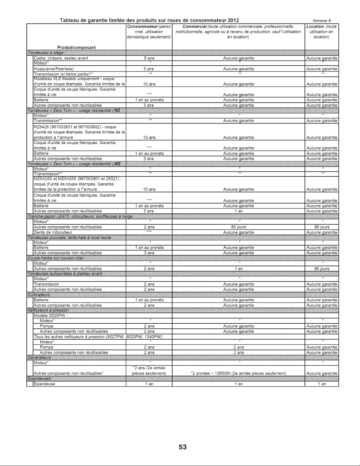
Tableau de garantie limit_e des produits sur roues de consommateur 2012
Produit/composant
Cadre, chassis, essieu avant
Moteur*
Husqvarna/Peerless)
Transmission (si tierce pattie)**
Modeless XLS Models uniquement - coque
d'unite de coupe etamp6e. Garantie limitee de la
Coque d'unite de coupe fabriquee. Garantie
limitee a vie
Batterie
Autres composants non reutilisables
Moteur*
Transmission**
RZ5426 (967003601 et 967003602) - coque
d'unite de coupe etamp6e. Garantie limitee de la
)rotection a I"armure
Coque d'unite de coupe fabriquee. Garantie
limitee a vie
Batterie
Autres cemposants non reutilisables
Moteur*
Transmission**
MZ5424S et MZ5425S (967003901 et 25021) -
coque d'unite de coupe etamp6e. Garantie
limitee de la protection a I"armure
Coque d'unite de coupe fabriquee. Garantie
limitee a vie
Batterie
Autres composants non reutilisables
Consommateur (perse
nnel, utilisation
domestique aeulement)
iii[ii!_ii!Jii{i!Jii{i!Jii{i!Jii{i!_ii{iiiiiiiIIi_[_[iiiiHiii[iI!_Ii!_1[i_ii!_ii{i!_ii{i!_ii{iiii!
5 ans
3 ans
10 arts
I an au prorata
3 ans
10 ans
I an au prorata
3 ans
10 ans
I an au prorata
3 ans
Commercial (toute utilisation commemiale, professionnelle,
institutionnelle, agricole ou_ revenu de production, sauf I'utilisation
en location)
ii1iii!_ii!_ii{i!_ii{i!_ii{i!_ii{i!_ii{i!_ii{i!_ii{i!_ii{i!_ii{i!_ii{i!_ii{i!_ii{i!_ii{i!_ii{i!_ii{i!_ii{i!_ii{i!_ii{i!_iiiiiiiiiiiiii_iiiiiii`i`ii!iii_ii[ii_i`iiiiii_iii[iIiii_iiii[_[E_iiii[!!iiiI[[_i_iiii!_ii{i!_ii{i!_ii{i!_ii{i!_ii{i!_ii{i!_ii{i!_ii{i!_ii{i!_ii{i!_ii{i!_ii{i!_ii{i!_ii{i!_ii{i!_ii{i!_ii{ii
Aucune ._arantie
Aucune garantie
Aucune garantie
Aucune garantie
Aucune garantie
Aucune garantie
Aucune garantie
Aucune garantie
Aucune garantie
Aucune garantie
Aucune garantie
Aucune garantie
Aucune garantie
I an
Annexe A
Locadon _oute
u_ation en
_cat_
Aucune garantie
Aucune garantie
Aucune garantie
Aucune garantie
Aucune garantie
iiiiiiiii i iiii
Aucune garantie
Aucune garantie
Aucune garantie
Aucune garantie
Aucune garantie
}i
Aucune garantie
Aucune garantie
Aucune garantie
Aucune garantie
90 jours 90 jours
Aucune garantie
Aucune garantie
Aucune garantie
90 jours
_itttttti tit1
Aucune garantie
Aucune garantie
Aucune garantie
Aucune garantie
Aucune garantie
Aucune garantie
Aucune garantie
Aucune garantie
1 an
Moteur*
Autres composants non reutilisables
Dents de rotoculteur
Moteur*
Batterie
Autres composants non reutilisables
Moteur*
Autres composants non reutilisables
Moteur*
Transmission
Autres composants non reutilisables
:iC / :;[;[;[;[;[;[;[
Batterie
Autres composants non reutilisables
Modele 5525PW :
Moteur*
Pompe
Autres composants non reutilisables
2 arts
I an au prorata
3 arts
2 arts
2 ans
2 arts
I an au prorata
2 ans
2 ans
2 arts
Tousles autres nettoyeurs b pression (6027PW, 9032PW, f340PW)
Moteur* *
Pompe 2 ans
Autres composants non rcutilisables 2 ans
_ iittttttttttttttttttttttiiii ttttttttt ittttt
• 2 arts (2e annee
pieces seulement)
I an
Moteur*
[Autres composants non reutilisables*
IEpandeuse
Aucune garantie
Aucune garantie
I an
ttttttttttttttttttttttttt_,,,,_i:ittttttttttttttttttttt
Aucune garantie
Aucune garantie
Aucune garantie
Aucune garantie
it_ ittttttttttttttttttttttttttttttttttttttttttttttt
Aucune garantie
Aucune garantie
2 ans
2 ans
:' :' :' :' : i ttttttttttttttttttttttt,,
*2 annees - 1365GN (2e annee pieces seulement)
I an
53
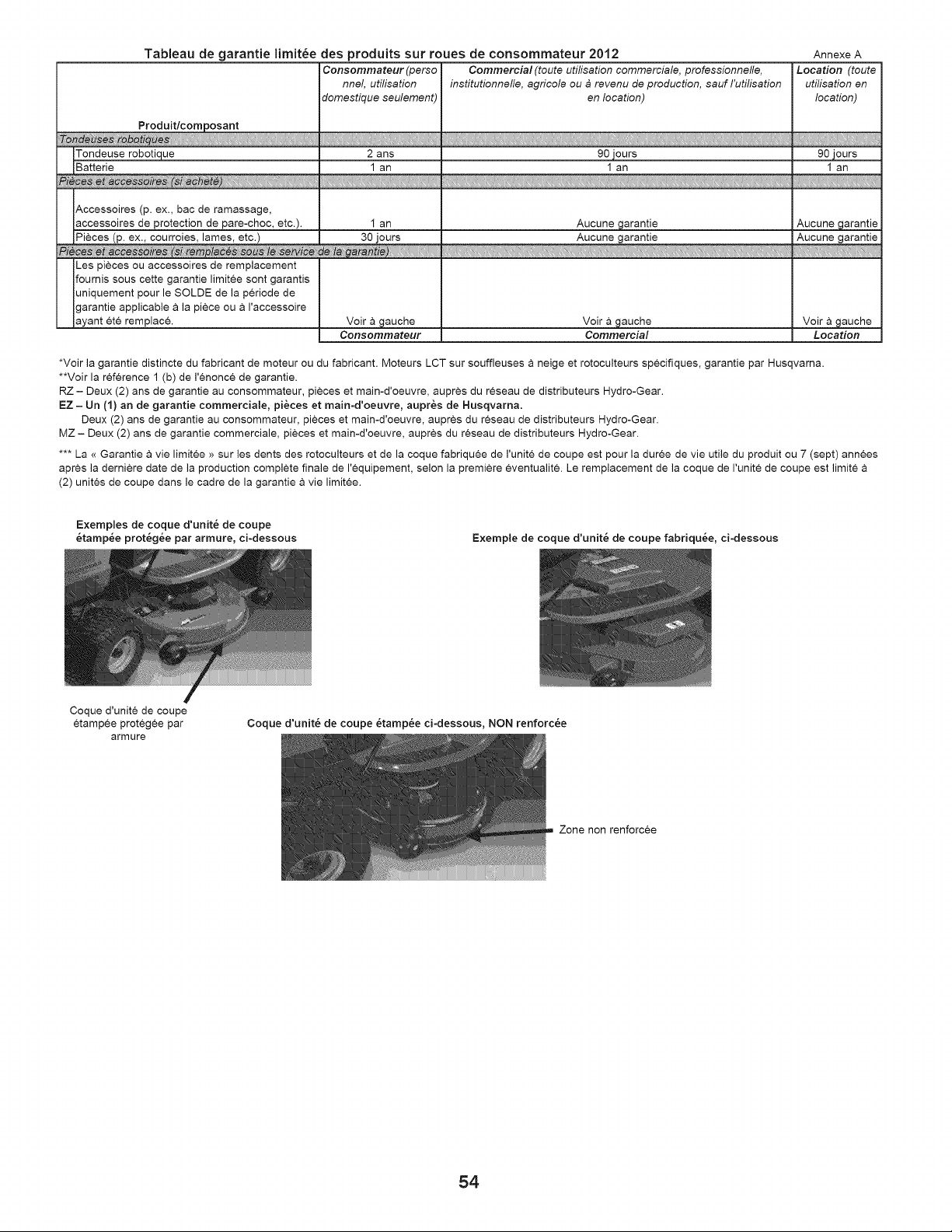
Tableau de garantie limit_e des produits sur roues de consommateur 2012 Annexe A
Consommateur (perso Commercial (toute utilisation commerciale, professionnefle, Location (toute
nnel, uti/isation institutionnefle, agricole ou _ revenu de production, sauf /'utilisation uti/isation en
domestique seulement) en location) location)
Tondeuse robotique 2 ans 90 jours 90 jours
Batterie 1 an 1 an I an
Accessoires (p. ex., bac de ramassage,
accessoires de protection de pare-choc, etc.).
I
Les pieces ou accessoires de remplacement
fournis sous cette garantie limitee sont garantis
uniquement pour le SOLDE de la periode de
garantie applicable a la piece ou & I'accessoire
ayant et6 remplac&
I an
Voir & gauche
Consommateur
Aucune garantie
Voir & gauche
Commercial
Aucune garantie
Voir & gauche
Location
*Voir la garantie distincte du fabricant de moteur ou du fabricant. Moteurs LCT sur souffleuses a neige et rotoculteurs specifiques, garantie par Husqvarna.
**Voir la reference 1 (b) de I'¢nonce de garantie.
RZ - Deux (2) ans de garantie au consommateur, pieces et main-d'oeuvre, aupres du reseau de distributeurs Hydro-Gear.
EZ - Un (1) an de garantie commerciale, pi&ces et main-d'oeuvre, aupr6s de Husqvarna.
Deux (2) ans de garantie au consommateur, pieces et main-d'oeuvre, aupres du reseau de distributeurs Hydro-Gear.
MZ - Deux (2) ans de garantie commerciale, pieces et main-d'oeuvre, aupres du reseau de distributeurs Hydro-Gear.
*** La <<Garantie a vie limitee >>sur les dents des rotoculteurs et de la coque fabriquee de I'unite de coupe est pour la duree de vie utile du produit ou 7 (sept) annees
apres la derniere date de la production complete finale de I'equipement, selon la premiere eventualit6. Le remplacement de la coque de I'unite de coupe est limite
(2) unites de coupe clans le cadre de la garantie a vie limitee.
Exemples de coque d'unit_ de coupe
6tamp_e protegee par armure, ci-dessous Exemple de coque d'unit_ de coupe fabriqu_e, ci-dessous
Coque d'unite de coupe
etamp6e proteg6e par
armure
Coque d'unit_ de coupe 6tamp_e ci-dessous, NON renforc&e
Zone non renforcee
54

REMARQUES D'ENTRETIEN
55

03/06/2013 BY