®
I
m
Owner's Manual
532 43 58-47
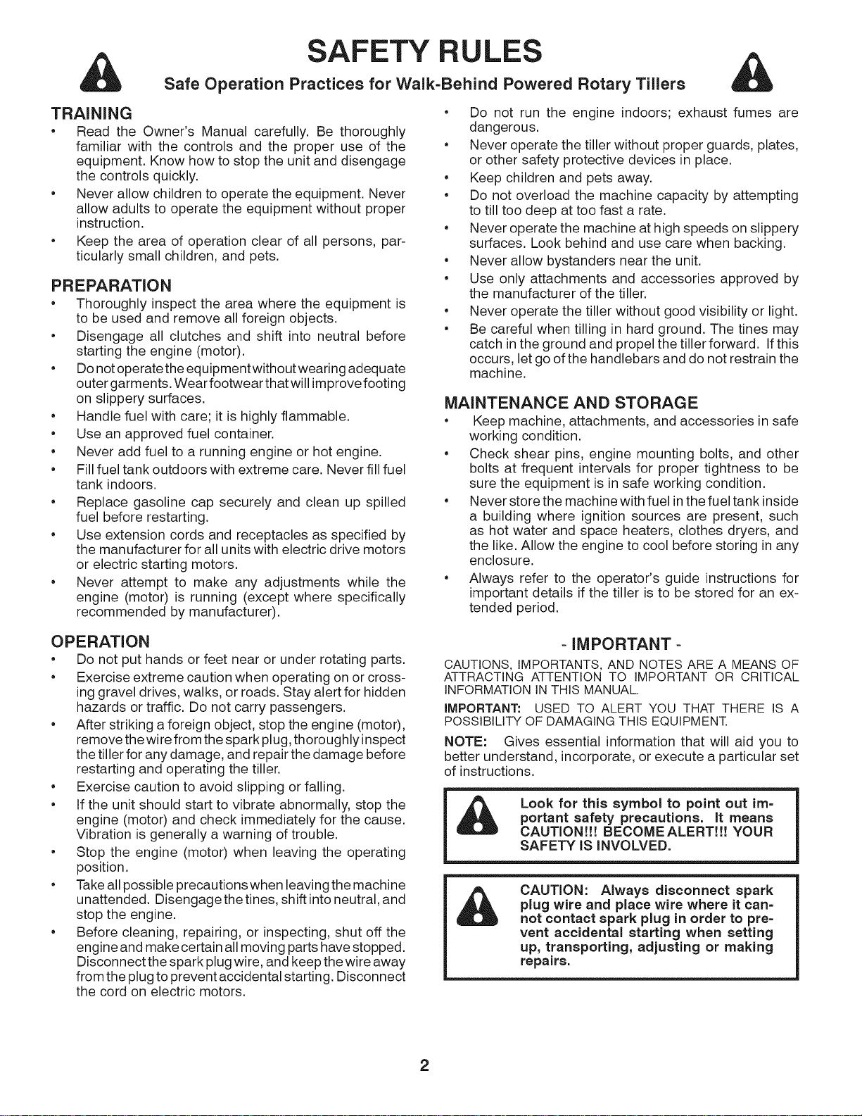
SAFETY RULES
Safe Operation Practices for Walk=Behind Powered Rotary Tillers
TRAiNiNG
• Read the Owner's Manual carefully. Be thoroughly
familiar with the controls and the proper use of the
equipment. Know how to stop the unit and disengage
the controls quickly.
• Never allow children to operate the equipment. Never
allow adults to operate the equipment without proper
instruction.
• Keep the area of operation clear of all persons, par-
ticularly small children, and pets.
PREPARATION
• Thoroughly inspect the area where the equipment is
to be used and remove all foreign objects.
• Disengage all clutches and shift into neutral before
starting the engine (motor).
• Do not operatethe equipmentwithout wearing adequate
outer garments. Wear footwear that will improvefooting
on slippery surfaces.
• Handle fuel with care; it is highly flammable.
• Use an approved fuel container.
• Never add fuel to a running engine or hot engine.
• Fill fuel tank outdoors with extreme care. Never fill fuel
tank indoors.
• Replace gasoline cap securely and clean up spilled
fuel before restarting.
• Use extension cords and receptacles as specified by
the manufacturer for all units with electric drive motors
or electric starting motors.
• Never attempt to make any adjustments while the
engine (motor) is running (except where specifically
recommended by manufacturer).
• Do not run the engine indoors; exhaust fumes are
dangerous.
• Never operate the tiller without proper guards, plates,
or other safety protective devices in place.
• Keep children and pets away.
• Do not overload the machine capacity by attempting
to till too deep at too fast a rate.
• Never operate the machine at high speeds on slippery
surfaces. Look behind and use care when backing.
• Never allow bystanders near the unit.
• Use only attachments and accessories approved by
the manufacturer of the tiller.
• Never operate the tiller without good visibility or light.
• Be careful when tilling in hard ground. The tines may
catch in the ground and propel the tiller forward. If this
occurs, let go of the handlebars and do not restrain the
machine.
MAINTENANCE AND STORAGE
• Keep machine, attachments, and accessories in safe
working condition.
• Check shear pins, engine mounting bolts, and other
bolts at frequent intervals for proper tightness to be
sure the equipment is in safe working condition.
• Never store the machine with fuel in the fuel tank inside
a building where ignition sources are present, such
as hot water and space heaters, clothes dryers, and
the like. Allow the engine to cool before storing in any
enclosure.
• Always refer to the operator's guide instructions for
important details if the tiller is to be stored for an ex-
tended period.
OPERATION
• Do not put hands or feet near or under rotating parts.
• Exercise extreme caution when operating on or cross-
inggravel drives, walks, or roads. Stay alert for hidden
hazards or traffic. Do not carry passengers.
• After striking a foreign object, stop the engine (motor),
remove the wire from the spark plug, thoroughly inspect
the tiller for any damage, and repair the damage before
restarting and operating the tiller.
• Exercise caution to avoid slipping or falling.
• if the unit should start to vibrate abnormally, stop the
engine (motor) and check immediately for the cause.
Vibration is generally a warning of trouble.
• Stop the engine (motor) when leaving the operating
position.
• Take all possible precautions when leaving the machine
unattended. Disengage the tines, shift intoneutral, and
stop the engine.
• Before cleaning, repairing, or inspecting, shut off the
engine and make certain all moving parts have stopped.
Disconnect the spark plug wire, and keep the wire away
from the plug to prevent accidental starting. Disconnect
the cord on electric motors.
-IMPORTANT-
CAUTIONS, IMPORTANTS, AND NOTES ARE A MEANS OF
ATTRACTING ATTENTION TO IMPORTANT OR CRITICAL
INFORMATION IN THIS MANUAL.
IMPORTANT: USED TO ALERT YOU THAT THERE IS A
POSSIBILITY OF DAMAGING THIS EQUIPMENT.
NOTE: Gives essential information that will aid you to
better understand, incorporate, or execute a particular set
of instructions.
Look for this symbol to point out im-
portant safety precautions. It means
CAUTION!!! BECOMEALERT!!! YOUR
SAFETY IS iNVOLVED.
&
CAUTION: Always disconnect spark
plug wire and place wire where it can=
not contact spark plug in order to pre-
vent accidental starting when setting
up, transporting, adjusting or making
repairs.
2
PRODUCT SPECIFICATIONS
Gasoline Capacity: 3 Quarts (2.8L)
Unleaded Regular
Oil (API-SG-SL): SAE 30 (Above32°F/0°0)
(Capacity: 21 oz./0.6L) SAE 5w-30 (Below 32°F/0°0)
Spark Plug : Champion
(Gap: .030"/0.76mm) RC12YC
CONGRATULATIONS on your purchase of a new tiller. It
has been designed, engineered and manufactured to give
you the best possible dependability and performance.
Should you experience any problems you cannot easily
remedy, please contact your nearest authorized service
center. We have competent, well-trained technicians and
the proper tools to service or repair this unit.
Please read and retain this manual. The instructions will
enable you to assemble and maintain your tiller properly.
Always observe the "SAFETY RULES".
CUSTOMER RESPONSIBILITIES
• Read and observe the safety rules.
• Follow a regular schedule in maintaining, caring for
and using your tiller.
• Follow instructions under"Maintenance" and "Storage"
sections of this Owner's Manual.
iMPORTANT: THIS UNIT IS EQUIPPED WITH AN INTERNAL
COMBUSTION ENGINE AND SHOULD NOT BE USED ON
OR NEAR ANY UNIMPROVED FOREST-COVERED, BRUSH-
COVERED OR GRASS COVERED LAND UNLESS THE
ENGINE'S EXHAUST SYSTEM IS EQUIPPED WITH A SPARK
ARRESTER MEETING APPLICABLE LOCAL LAWS (IF ANY).
IFA SPARKARRESTER IS USED, ITSHOULD BE MAINTAINED
IN EFFECTIVE WORKING ORDER BY THE OPERATOR.
IN THE STATE OF CALIFORNIA, A SPARK ARRESTER IS
REQUIRED BY LAW (SECTION 4442 OF THE CALIFORNIA
PUBLIC RESOURCES CODE). OTHER STATES MAY HAVE
SIMILAR LAWS. FEDERAL LAWSAPPLYON FEDERAL LANDS.
SEE YOUR AUTHORIZED SERVICE CENTER/DEPARTMENT
FOR SPARK ARRESTER.
TABLE OF CONTENTS
SAFETY RULES ............................................................ 2
CUSTOMER RESPONSIBILITIES ................................. 3
PRODUCT SPECIFICATIONS ....................................... 3
ASSEMBLY ................................................................. 4=5
OPERATION ............................................................... 6-9
MAINTENANCE SCHEDULE ...................................... 10
MAINTENANCE ...................................................... 10=12
SERVICE & ADJUSTMENTS ................................. 13=15
STO RAG E.................................................................... 16
TROUBLESHOOTING ................................................. 17
REPAIR PARTS ...................................................... 18=23
WARRANTY ............................................. BACK COVER
3
ASSEMBLY
Your new tiller has been assembled at the factory with exception of those parts left unassembled for shipping purposes.
To ensure safe and proper operation of your tiller all parts and hardware you assemble must be tightened securely. Use
the correct tools as necessary to insure proper tightness.
TOOLS REQUIRED FOR ASSEMBLY
A socket wrench set will make assembly easier. Standard
wrench sizes are listed.
(1) Utility knife
(1) Screwdriver
(1) Pair of pliers
(2) 1/2" wrenches
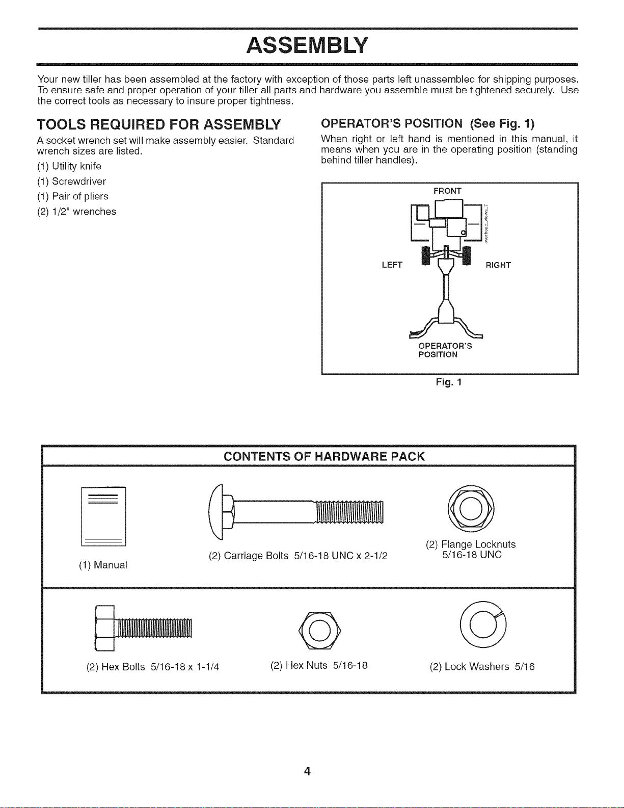
OPERATOR'S POSITION (See Fig. 1)
When right or left hand is mentioned in this manual, it
means when you are in the operating position (standing
behind tiller handles).
FRONT
LEFT RIGHT
OPERATOR'S
POSITION
Fig. 1
CONTENTS OF HARDWARE PACK
(1) Manual
(2) Carriage Bolts 5/16-18 UNC x 2-1/2
O
(2) Flange Locknuts
5/16-18 UNC
(2) Hex Bolts 5/16-18 x 1-1/4
Q
(2) Hex Nuts 5/16-18
(2) Lock Washers 5/16
4
ASSEMBLY
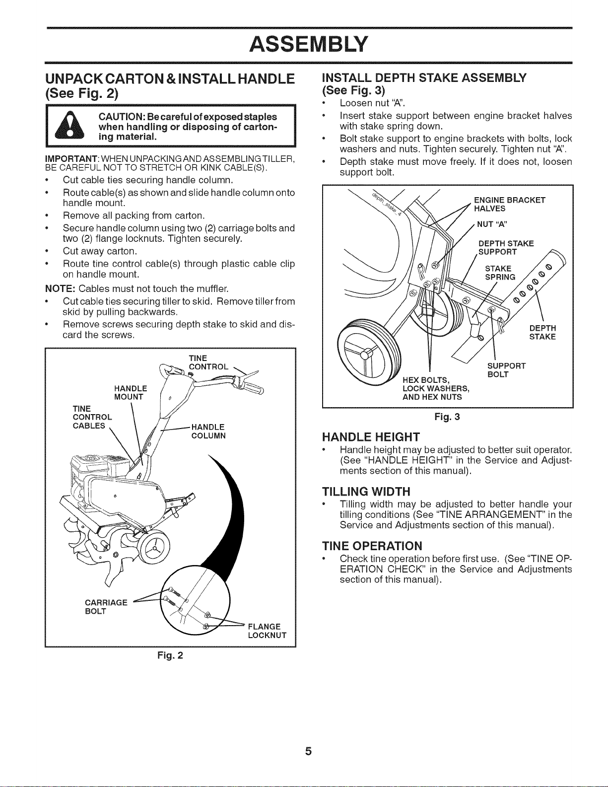
UNPACK CARTON & iNSTALL HANDLE
See Fig. 2)
CAUTION: Be careful of exposed staples
when handling or disposing of carton=
ing material.
IMPORTANT:WHEN UNPACKINGANDASSEMBLINGTILLER,
BE CAREFUL NOT TO STRETCH OR KINK CABLE(S).
Cut cable ties securing handle column.
Route cable(s) as shown and slide handle column onto
handle mount.
• Remove all packing from carton.
• Secure handle column using two (2) carriage bolts and
two (2) flange Iocknuts. Tighten securely.
• Cut away carton.
• Route tine control cable(s) through plastic cable clip
on handle mount.
NOTE: Cables must not touch the muffler.
Cut cable ties securing tiller to skid. Remove tiller from
skid by pulling backwards.
Remove screws securing depth stake to skid and dis-
card the screws.
TINE
CONTROL
CABLES
TINE
HANDLE
MOUNT
i/_..--.---HANDLE
COLUMN
CARRIAGE
BO_
FLANGE
LOCKNUT
iNSTALL DEPTH STAKE ASSEMBLY
(See Fig. 3)
Loosen nut '_'.
• Insert stake support between engine bracket halves
with stake spring down.
• Bolt stake support to engine brackets with bolts, lock
washers and nuts. Tighten securely. Tighten nut '_'.
• Depth stake must move freely. If it does not, loosen
support bolt.
ENGINE BRACKET
HALVES
NUT "A"
DEPTH STAKE
SUPPORT
STAKE
SPRING
DEPTH
STAKE
HEX BOLTS,
LOCK WASHERS,
AND HEX NUTS
SUPPORT
BOLT
Fig. 3
HANDLE HEIGHT
Handle height may be adjusted to better suit operator.
(See "HANDLE HEIGHT" in the Service and Adjust-
ments section of this manual).
TILLING WIDTH
• Tilling width may be adjusted to better handle your
tilling conditions (See "TINE ARRANGEMENT" in the
Service and Adjustments section of this manual).
TiN E OPERATION
Check tire operation before first use. (See "TINE OP-
ERATION CHECK" in the Service and Adjustments
section of this manual).
Fig. 2
5
OPERATION
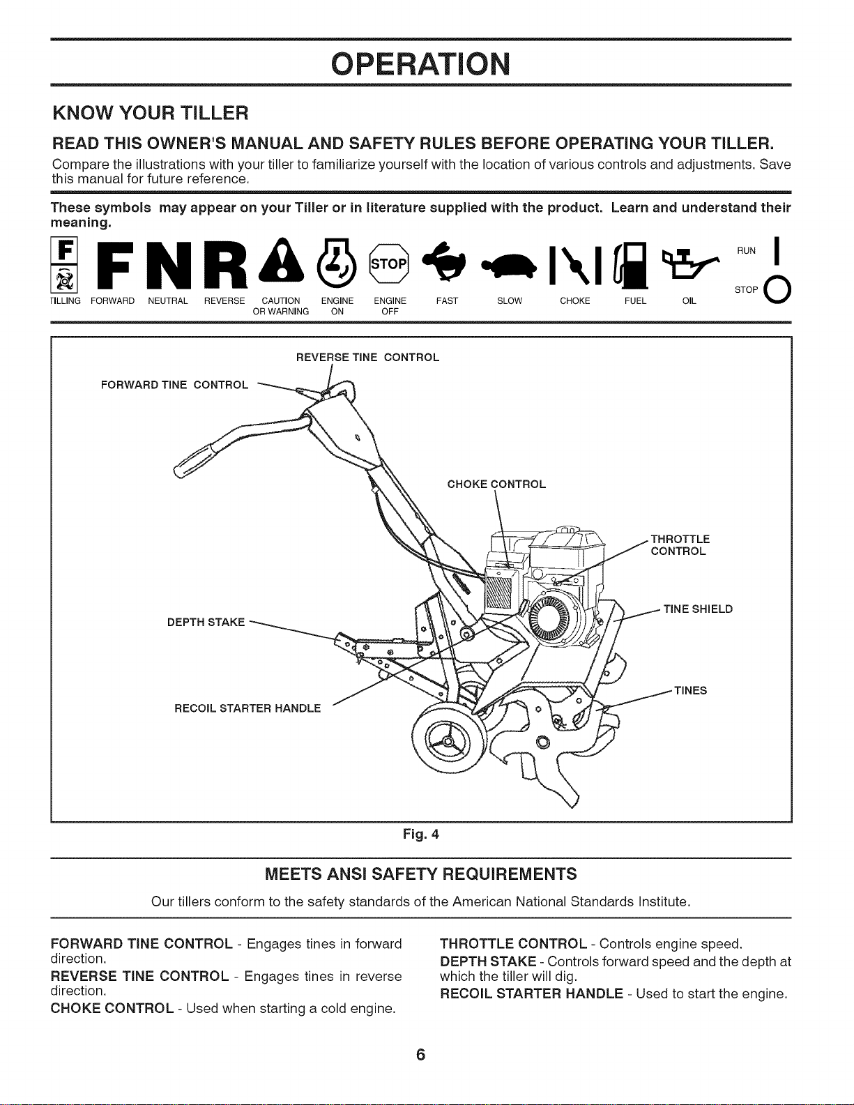
KNOW YOUR TILLER
READ THIS OWNER'S MANUAL AND SAFETY RULES BEFORE OPERATING YOUR TILLER.
Compare the illustrations with your tiller to familiarize yourself with the location of various controls and adjustments. Save
this manual for future reference.
These symbols may appear on your Tiller or in literature supplied with the product. Learn and understand their
meaning.
F N R& -,,,,I",lrl
TILLING FORWARD NEUTRAL REVERSE CAUTION ENGINE ENGINE FAST SLOW CHOKE FUEL OIL
OR WARNING ON OFF
FORWARD TINE CONTROL
REVERSE TINE CONTROL
CHOKE CONTROL
CONTROL
DEPTH STAKE
SHIELD
RECOIL STARTER HANDLE
0
Fig. 4
MEETS ANS! SAFETY REQUIREMENTS
Our tillers conform to the safety standards of the American National Standards Institute.
FORWARD TINE CONTROL - Engages tines in forward
direction.
REVERSE TINE CONTROL - Engages tines in reverse
direction.
CHOKE CONTROL - Used when starting a cold engine.
THROTTLE CONTROL - Controls engine speed.
DEPTH STAKE - Controls forward speed and the depth at
which the tiller will dig.
RECOIL STARTER HANDLE - Used to start the engine.
6
OPERATION
The operation of any tiller can result in foreign objects thrown into the eyes, which can result
in severe eye damage. Always wear safety glasses or eye shields before starting your til-
ler and while tilling. We recommend a wide vision safety mask over spectacles or standard
safety glasses.
HOW TO USE YOUR TILLER
Know how to operate all controls before adding fuel and
oil or attempting to start engine.
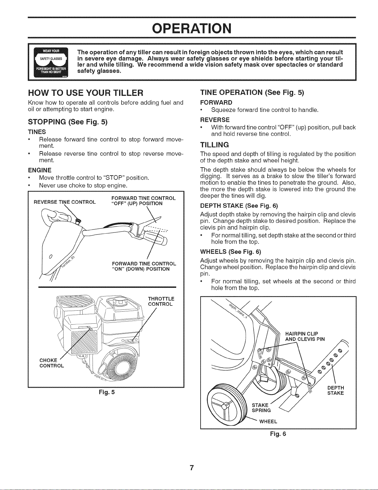
STOPPING (See Fig. 5)
TINES
• Release forward tine control to stop forward move-
ment.
• Release reverse tine control to stop reverse move-
ment.
ENGINE
• Move throttle control to "STOP" position.
• Never use choke to stop engine.
FORWARD TINE CONTROL
REVERSE TINE CONTROL "OFF" (UP) POSiTiON
_ OL
JIj'_'/÷_/t._// "ON" (DOWN) POSITION
THROTTLE
CONTROL
CHOKE
CONTROL
Fig. 5
TINE OPERATION (See Fig. 5)
FORWARD
• Squeeze forward tine control to handle.
REVERSE
• With forward tine control "OFF" (up) position, pull back
and hold reverse tine control.
TILLING
The speed and depth of tilling is regulated by the position
of the depth stake and wheel height.
The depth stake should always be below the wheels for
digging. It serves as a brake to slow the tiller's forward
motion to enable the tines to penetrate the ground. Also,
the more the depth stake is lowered into the ground the
deeper the tines will dig.
DEPTH STAKE (See Fig. 6)
Adjust depth stake by removing the hairpin clip and clevis
pin. Change depth stake to desired position. Replace the
clevis pin and hairpin clip.
• For normal tilling, set depth stake at the second or third
hole from the top.
WHEELS (See Fig. 6)
Adjust wheels by removing the hairpin clip and clevis pin.
Change wheel position. Replace the hairpin clip and clevis
pin.
• For normal tilling, set wheels at the second or third
hole from the top.
HAIRPIN CLiP
AND CLEVIS PIN
DEPTH
STAKE
WHEEL
Fig. 6
7
OPERATION
TO TRANSPORT
CAUTION: Before lifting or transporting,
aJiow tiller engine and muffler to cool.
Disconnect spark plug wire. Drain
gasoline from fuel tank.
AROUND THE YARD
• Tip depth stake forward until it is held by the stake
spring.
Push tiller handles down, raising tines off the ground.
Push or pull tiller to desired location.
AROUND TOWN
Disconnect spark plug wire.
Drain fuel tank.
• Transport in upright position to prevent oil leakage.
BEFORE STARTING ENGINE
iMPORTANT: BE VERY CAREFUL NOT TO ALLOW DIRT
TO ENTER THE ENGINE WHEN CHECKING OR ADDING
OIL OR FUEL. USE CLEAN OIL AND FUEL AND STORE IN
APPROVED, CLEAN, COVEREDCONTAINERS. USECLEAN
FILL FUNNELS.
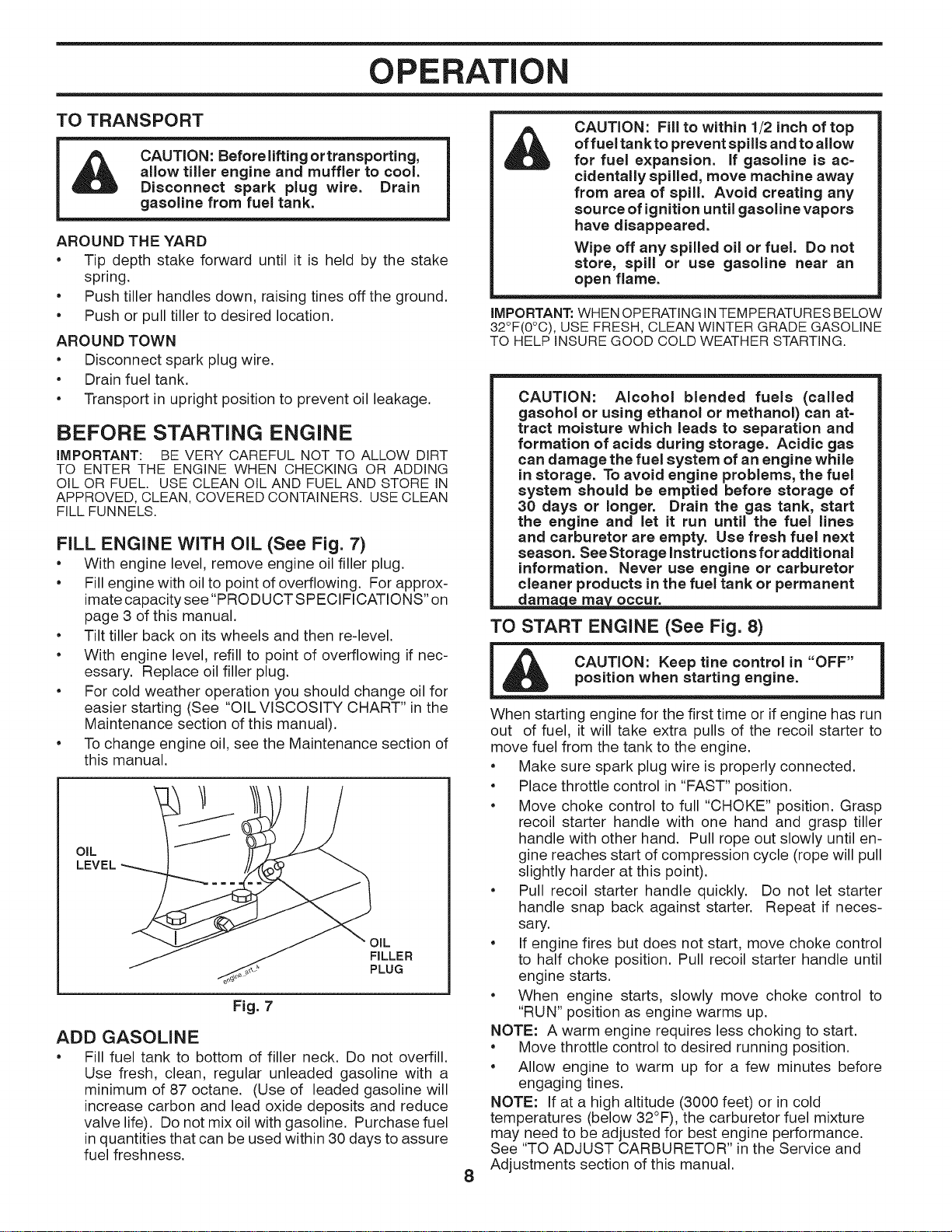
FILL ENGINE WITH OiL (See Fig. 7)
• With engine level, remove engine oil filler plug.
• Fill engine with oil to point of overflowing. For approx-
imate capacity see "PRODUCT SPECIFICATIONS" on
page 3 of this manual.
• Tilt tiller back on its wheels and then re-level.
• With engine level, refill to point of overflowing if nec-
essary. Replace oil filler plug.
• For cold weather operation you should change oil for
easier starting (See "OIL VISCOSITY CHART" in the
Maintenance section of this manual).
• To change engine oil, see the Maintenance section of
this manual.
OIL
LEVEL
OIL
FILLER
PLUG
Fig. 7
ADD GASOLINE
• Fill fuel tank to bottom of filler neck. Do not overfill.
Use fresh, clean, regular unleaded gasoline with a
minimum of 87 octane. (Use of leaded gasoline will
increase carbon and lead oxide deposits and reduce
valve life). Do not mix oil with gasoline. Purchase fuel
in quantities that can be used within 30 days to assure
fuel freshness.
8
CAUTION: Fill to within 1/2 inch of top
offuel tankto prevent spills and to allow
for fuel expansion. If gasoline is ac=
cidentally spilled, move machine away
from area of spill. Avoid creating any
source of ignition until gasoline vapors
have disappeared.
Wipe off any spilled oil or fuel. Do not
store, spill or use gasoline near an
open flame.
IMPORTANT." WHEN OPERATING IN TEMPERATURES BELOW
32°F(0°C), USE FRESH, CLEAN WINTER GRADE GASOLINE
TO HELP INSURE GOOD COLD WEATHER STARTING.
CAUTION: Alcohol blended fuels (called
gasohol or using ethanol or methanol) can at=
tract moisture which leads to separation and
formation of acids during storage. Acidic gas
can damage the fuel system of an engine while
in storage. To avoid engine problems, the fuel
system should be emptied before storage of
30 days or longer. Drain the gas tank, start
the engine and let it run until the fuel lines
and carburetor are empty. Use fresh fuel next
season. See Storage Instructions for additional
information. Never use engine or carburetor
cleaner products in the fuel tank or permanent
TO START ENGINE (See Fig. 8)
= m
i CAUTION: Keep tine control in "OFF"
m
position when starting engine.
When starting engine for the first time or ifengine has run
out of fuel, it will take extra pulls of the recoil starter to
move fuel from the tank to the engine.
• Make sure spark plug wire isproperly connected.
• Place throttle control in "FAST" position.
• Move choke control to full "CHOKE" position. Grasp
recoil starter handle with one hand and grasp tiller
handle with other hand. Pull rope out slowly until en-
gine reaches start of compression cycle (rope will pull
slightly harder at this point).
• Pull recoil starter handle quickly. Do not let starter
handle snap back against starter. Repeat if neces-
sary.
• If engine fires but does not start, move choke control
to half choke position. Pull recoil starter handle until
engine starts.
• When engine starts, slowly move choke control to
"RUN" position as engine warms up.
NOTE: A warm engine requires less choking to start.
• Move throttle control to desired running position.
• Allow engine to warm up for a few minutes before
engaging tines.
NOTE: If at a high altitude (3000 feet) or in cold
temperatures (below 32°F), the carburetor fuel mixture
may need to be adjusted for best engine performance.
See "TO ADJUST CARBURETOR" in the Service and
Adjustments section of this manual.
OPERATION
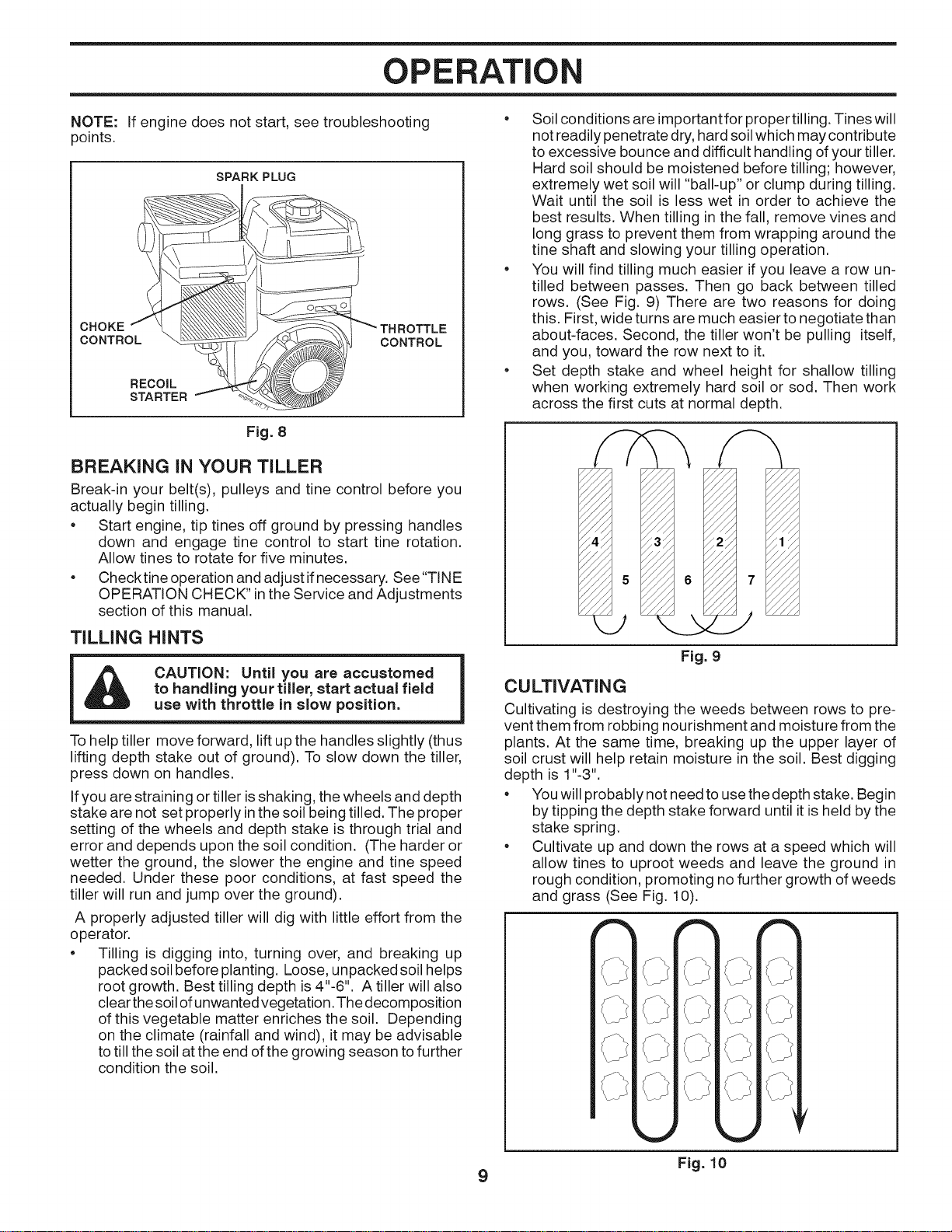
NOTE: If engine does not start, see troubleshooting
points.
SPARK PLUG
CHOKE
CONTROL
RECOIL
STARTER
CONTROL
Fig. 8
BREAKING IN YOUR TILLER
Break-in your belt(s), pulleys and tine control before you
actually begin tilling.
• Start engine, tip tines off ground by pressing handles
down and engage tine control to start tine rotation.
Allow tines to rotate for five minutes.
• Checktine operation and adjust ifnecessary. See"TINE
OPERATION CHECK" inthe Service and Adjustments
section of this manual.
TILLING HINTS
CAUTION: Until you are accustomed
to handling your tiller, start actual field
use with throttle in slow position.
To help tiller move forward, lift up the handles slightly (thus
lifting depth stake out of ground). To slow down the tiller,
press down on handles.
If you are straining or tiller is shaking, the wheels and depth
stake are not set properly in the soil being tilled. The proper
setting of the wheels and depth stake is through trial and
error and depends upon the soil condition. (The harder or
wetter the ground, the slower the engine and tine speed
needed. Under these poor conditions, at fast speed the
tiller will run and jump over the ground).
A properly adjusted tiller will dig with little effort from the
operator.
• Tilling is digging into, turning over, and breaking up
packedsoil before planting. Loose, unpackedsoil helps
root growth. Best tilling depth is 4"-6". A tiller will also
clear thesoil of unwanted vegetation. The decomposition
of this vegetable matter enriches the soil. Depending
on the climate (rainfall and wind), it may be advisable
to till the soil at the end of the growing season to further
condition the soil.
• Soil conditions are importantfor proper tilling. Tines will
not readily penetrate dry, hard soil which may contribute
to excessive bounce and difficult handling of your tiller.
Hard soil should be moistened before tilling; however,
extremely wet soil will "ball-up" or clump during tilling.
Wait until the soil is less wet in order to achieve the
best results. When tilling inthe fall, remove vines and
long grass to prevent them from wrapping around the
tine shaft and slowing your tilling operation.
• You will find tilling much easier if you leave a row un-
tilled between passes. Then go back between tilled
rows. (See Fig. 9) There are two reasons for doing
this. First, wide turns are much easier to negotiate than
about-faces. Second, the tiller won't be pulling itself,
and you, toward the row next to it.
• Set depth stake and wheel height for shallow tilling
when working extremely hard soil or sod. Then work
across the first cuts at normal depth.
Fig. 9
CULTIVATING
Cultivating is destroying the weeds between rows to pre-
vent them from robbing nourishment and moisture from the
plants. At the same time, breaking up the upper layer of
soil crust will help retain moisture in the soil. Best digging
depth is 1"-3".
• You will probably not need to use the depth stake. Begin
by tipping the depth stake forward until itisheld by the
stake spring.
• Cultivate up and down the rows at a speed which will
allow tines to uproot weeds and leave the ground in
rough condition, promoting no further growth of weeds
and grass (See Fig. 10).
9 Fig. 10
MAINTENANCE
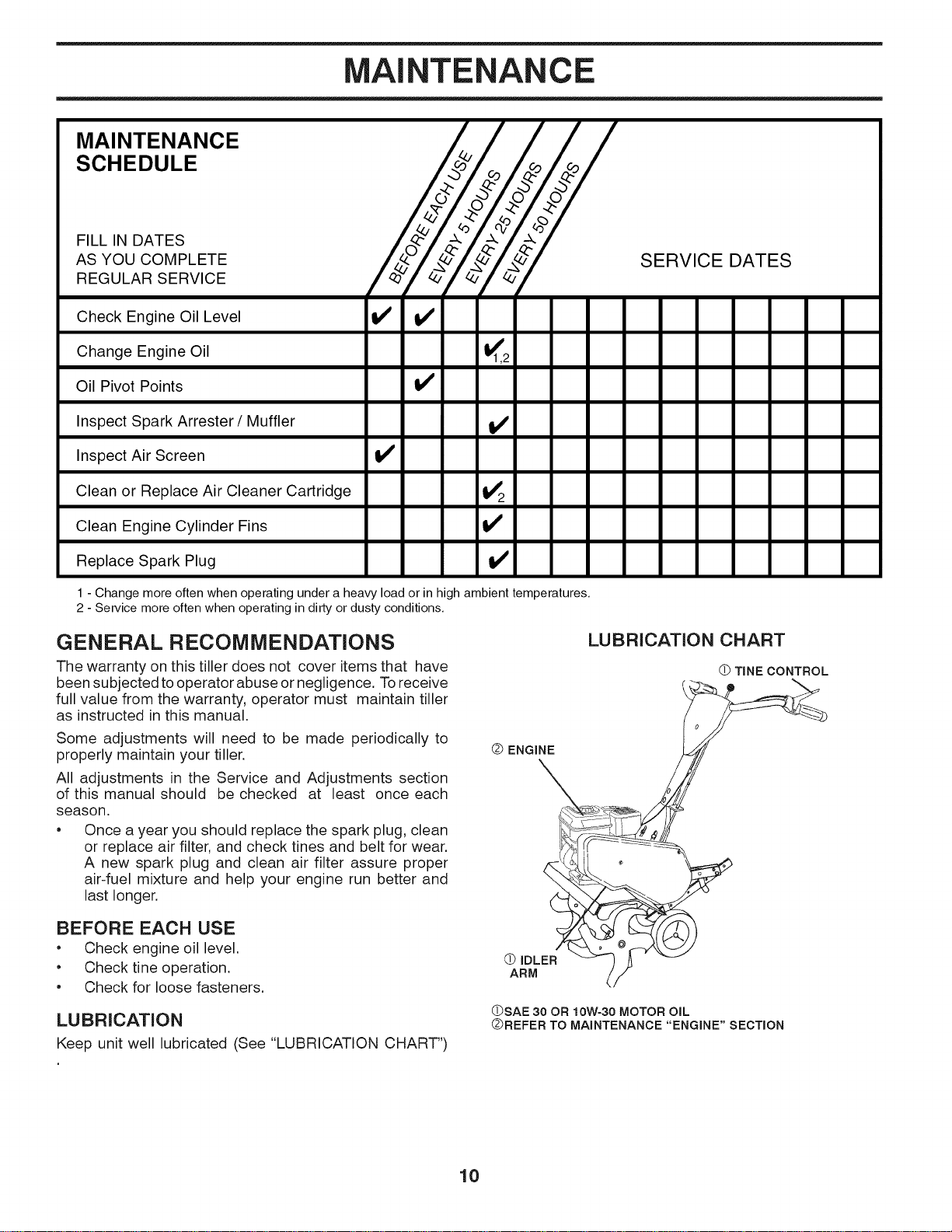
MAINTENANCE
SCHEDULE
FILL IN DATES
AS YOU COMPLETE
REGULAR SERVICE
Check Engine Oil Level v' v'
SERVICE DATES
Change Engine Oil !_1,2
Oil Pivot Points V'
Inspect Spark Arrester/Muffler V'
Inspect Air Screen If
Clean or Replace Air Cleaner Cartridge !_2
Clean Engine Cylinder Fins tf
Replace Spark Plug !_
1 - Change more often when operating under a heavy load or in high ambient temperatures,
2 - Service more often when operating in dirty or dusty conditions,
GENERAL RECOMMENDATIONS
The warranty on this tiller does not cover items that have
been subjected to operator abuse or negligence. Toreceive
full value from the warranty, operator must maintain tiller
as instructed in this manual.
Some adjustments will need to be made periodically to
properly maintain your tiller.
All adjustments in the Service and Adjustments section
of this manual should be checked at least once each
season.
• Once a year you should replace the spark plug, clean
or replace air filter, and check tines and belt for wear.
A new spark plug and clean air filter assure proper
air-fuel mixture and help your engine run better and
last longer.
BEFORE EACH USE
• Check engine oil level.
• Check tine operation.
• Check for loose fasteners.
LUBRICATION
Keep unit well lubricated (See "LUBRICATION CHART")
Q ENGINE
LUBRICATION CHART
(_ TINE CONTROL
(_ IDLER
ARM
(DSAE 30 OR 10W-30 MOTOR OIL
QREFER TO MAINTENANCE "ENGINE" SECTION
10
MAINTENANCE
Disconnect spark plug wire before performing any maintenance (except carburetor adjustment) to
prevent accidental starting of engine.
Prevent fires! Keep the engine free of grass, leaves, spilled oil, or fuel. Remove fuel from tank
before tipping unit for maintenance. Clean muffler area of all grass, dirt, and debris.
Do not touch hot muffler or cylinder fins as contact may cause burns.
ENGINE
LUBRiCATiON
Use only high quality detergent oil rated with API service
classification SG-SL. Select the oil's SAE viscosity grade
according to your expected temperature.
SAE VISCOSITY GRADES
F
C
-20 0 30 32 40 60 80 100
-3'0 -2'0 -1; (3 1'0 20 3'0 4'0
TEMPERATURE RANGE ANTICIPATED BEFORE NEXT OIL CHANGE
oil visc chart1
Fig. 11
NOTE: Although multi-viscosity oils (5W-30, 10W-30, etc.)
improve starting in cold weather, these multi-viscosity oils
will result in increased oil consumption when used above
32°F (0°C). Check your engine oil level more frequently to
avoid possible engine damage from running low on oil.
Change the oil after every 50 hours of operation or at
least once a year if the tiller is not used for 50 hours in
one year.
Check the crankcase oil level before starting the engine
and after each five (5) hours of continuous use. Add SAE
30 motor oil or equivalent. Tighten oil filler plug securely
each time you check the oil level.
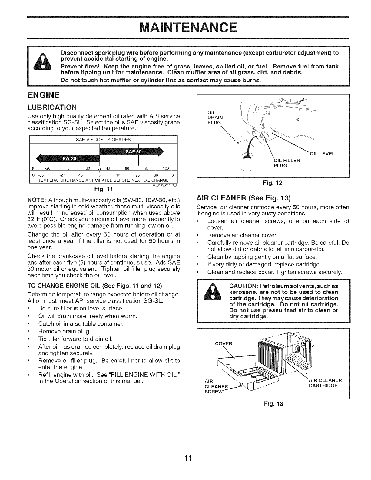
TO CHANGE ENGINE OiL (See Figs. 11 and 12)
Determine temperature range expected before oil change.
All oil must meet API service classification SG-SL.
• Be sure tiller ison level surface.
• Oil will drain more freely when warm.
• Catch oil in a suitable container.
• Remove drain plug.
• Tip tiller forward to drain oil.
• After oil has drained completely, replace oil drain plug
and tighten securely.
• Remove oil filler plug. Be careful not to allow dirt to
enter the engine.
• Refill engine with oil. See "FILL ENGINE WITH OIL"
in the Operation section of this manual.
OiL
DRAIN
PLUG
\
OIL FILLER
PLUG
OIL LEVEL
Fig. 12
AiR CLEANER (See Fig. 13)
Service air cleaner cartridge every 50 hours, more often
if engine is used in very dusty conditions.
• Loosen air cleaner screws, one on each side of
cover.
• Remove air cleaner cover.
• Carefully remove air cleaner cartridge. Be careful. Do
not allow dirt or debris to fall into carburetor.
• Clean by tapping gently on a flat surface.
• If very dirty or damaged, replace cartridge.
• Clean and replace cover. Tighten screws securely.
&
CAUTION: Petroleum solvents, such as
kerosene, are not to be used to clean
cartridge. They may cause deterioration
of the cartridge. Do not oil cartridge.
Do not use pressurized air to clean or
dry cartridge.
COVER_
AIR R CLEANER
0o% 7 CAR,R,OGE
Fig. 13
11
MAINTENANCE
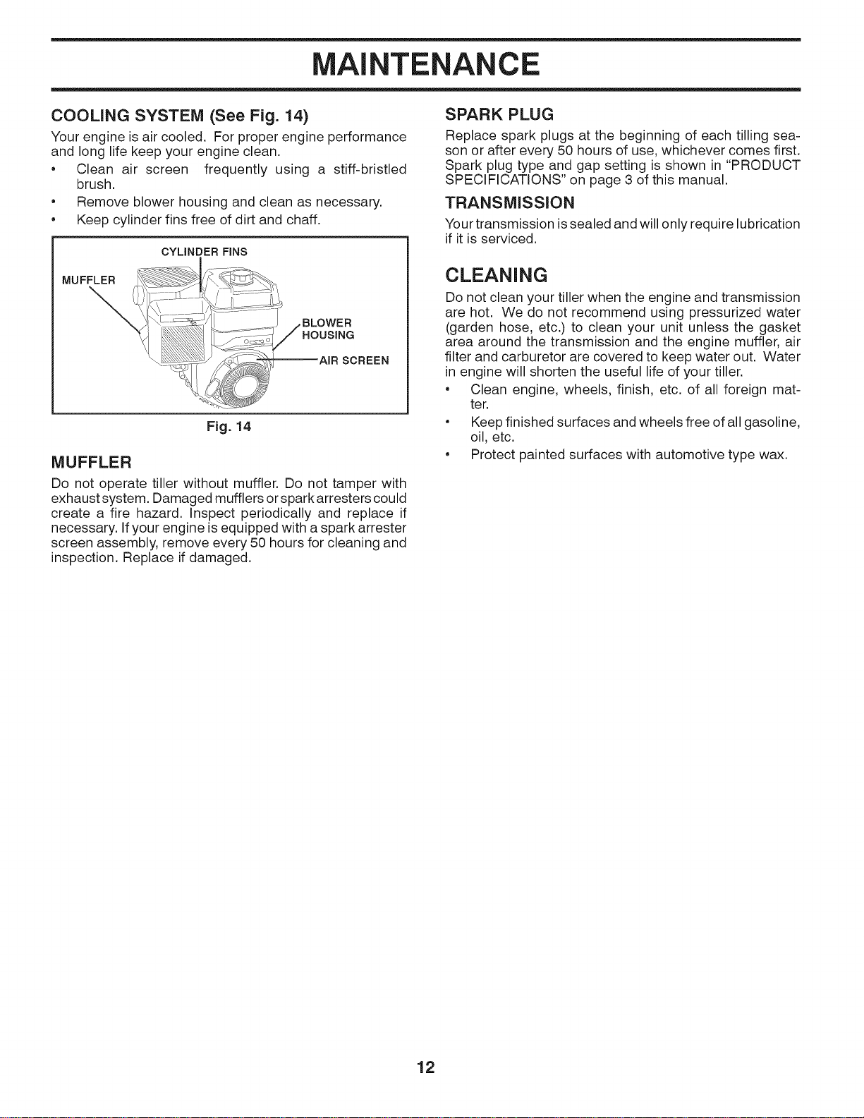
COOLING SYSTEM (See Fig. 14)
Your engine is air cooled. For proper engine performance
and long life keep your engine clean.
• Clean air screen frequently using a stiff-bristled
brush.
• Remove blower housing and clean as necessary.
• Keep cylinder fins free of dirt and chaff.
CYLINDER FINS
MUFFLER
\
Fig. 14
MUFFLER
Do not operate tiller without muffler. Do not tamper with
exhaust system. Damaged mufflers or spark arresters could
create a fire hazard. Inspect periodically and replace if
necessary. If your engine is equipped with a spark arrester
screen assembly, remove every 50 hours for cleaning and
inspection. Replace if damaged.
SPARK PLUG
Replace spark plugs at the beginning of each tilling sea-
son or after every 50 hours of use, whichever comes first.
Spark plug type and gap setting is shown in "PRODUCT
SPECIFICATIONS" on page 3 of this manual.
TRANSMISSION
Your transmission issealed and will only require lubrication
if it is serviced.
CLEANING
Do not clean your tiller when the engine and transmission
are hot. We do not recommend using pressurized water
(garden hose, etc.) to clean your unit unless the gasket
area around the transmission and the engine muffler, air
filter and carburetor are covered to keep water out. Water
in engine will shorten the useful life of your tiller.
• Clean engine, wheels, finish, etc. of all foreign mat-
ter.
• Keep finished surfaces and wheels free of all gasoline,
oil, etc.
• Protect painted surfaces with automotive type wax.
12
SERVICE AND ADJUSTMENTS
CAUTION: Disconnect spark plug wire from spark plug and place wire where it cannot come into
contact with plug.
TILLER
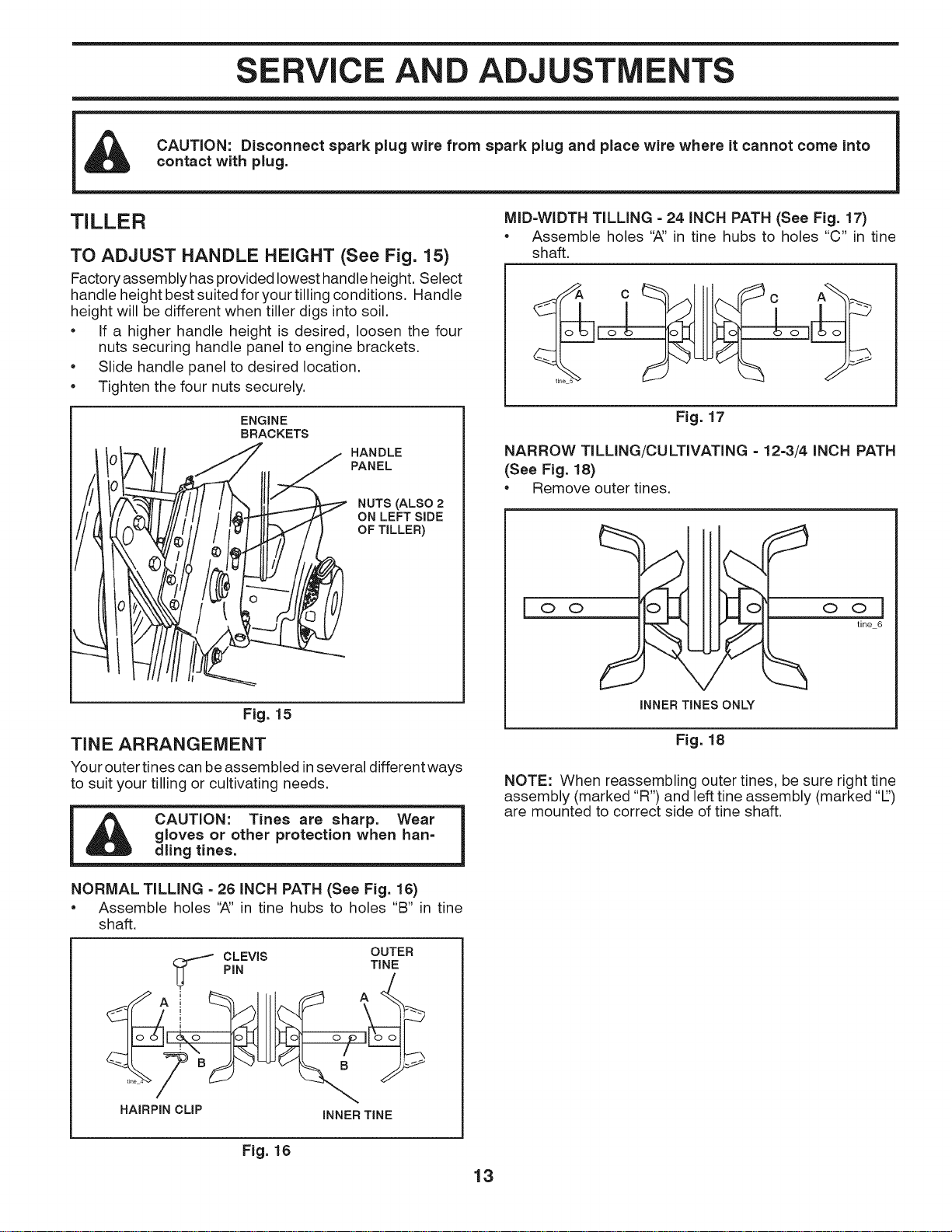
TO ADJUST HANDLE HEIGHT (See Fig. 15)
Factory assembly has provided lowest handle height. Select
handle height best suited for your tilling conditions. Handle
height will be different when tiller digs intosoil.
• If a higher handle height is desired, loosen the four
nuts securing handle panel to engine brackets.
• Slide handle panel to desired location.
• Tighten the four nuts securely.
ENGINE
BRACKETS
HANDLE
PANEL
NUTS (ALSO 2
ON LEFT SIDE
OF TILLER)
Fig. 15
TINE ARRANGEMENT
Your outer tines can be assembled in several different ways
to suit your tilling or cultivating needs.
i CAUTION: Tines are sharp. Wear
gloves or other protection when han= |
dling tines.
NORMAL TILLING = 26 INCH PATH (See Fig. 16)
• Assemble holes '_' in tine hubs to holes "B" in tine
shaft.
HAIRPIN CLIP INNER TINE
Fig. 16
13
MID=WIDTH TILLING =24 INCH PATH (See Fig. 17)
• Assemble holes '_' in tine hubs to holes "C" in tine
shaft.
Fig. 17
NARROW TILLING/CULTIVATING - 12-3/4 INCH PATH
(See Fig. 18)
• Remove outer tines.
• w===_ IP==4 •
oil I Io
INNER TINES ONLY
ool
tine 6
Fig. 18
NOTE: When reassembling outer tines, be sure right tine
assembly (marked "R") and left tine assembly (marked "1")
are mounted to correct side of tine shaft.
SERVICE AND ADJUSTMENTS
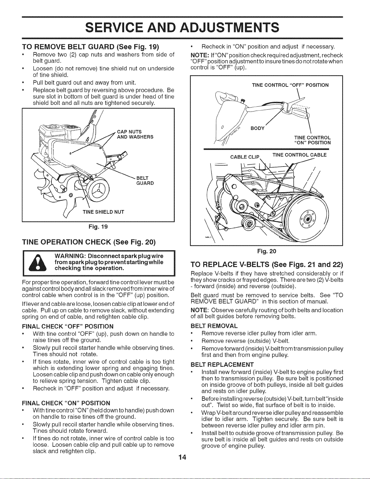
TO REMOVE BELT GUARD (See Fig. 19)
• Remove two (2) cap nuts and washers from side of
belt guard.
• Loosen (do not remove) tine shield nut on underside
of tine shield.
e
e
Pull belt guard out and away from unit.
Replace belt guard by reversing above procedure. Be
sure slot in bottom of belt guard is under head of tine
shield bolt and all nuts are tightened securely.
_"[-[_f /J A CAP NUTS
ANDWASHERS
_ / TINE SHIELD NUT
Fig. 19
TINE OPERATION CHECK (See Fig. 20)
WARNING: Disconnect spark plug wire
from spark plug to prevent starting while
checking tine operation.
For proper tine operation, forward tine control lever must be
against control body and all slack removed from innerwire of
control cable when control is in the "OFF" (up) position.
Iflever and cable are loose, loosen cable clip at lower end of
cable. Pull up on cable to remove slack, without extending
spring on end of cable, and retighten cable clip.
FINAL CHECK "OFF" POSITION
• With tine control "OFF" (up), push down on handle to
raise tines off the ground.
Slowly pull recoil starter handle while observing tines.
Tines should not rotate.
If tines rotate, inner wire of control cable is too tight
which is extending lower spring and engaging tines.
Loosen cable clip and push down on cable only enough
to relieve spring tension. Tighten cable clip.
Recheck in "OFF" position and adjust if necessary.
FINAL CHECK "ON" POSITION
• With tine control "ON" (held down to handle) push down
on handle to raise tines off the ground.
• Slowly pull recoil starter handle while observing tines.
Tines should rotate forward.
• If tines do not rotate, inner wire of control cable is too
loose. Loosen cable clip and pull cable up to remove
slack and retighten clip.
• Recheck in "ON" position and adjust if necessary.
NOTE: If"ON" position check required adjustment, recheck
"OFF" position adjustment to insure tines do not rotate when
control is "OFF" (up).
TINE CONTROL "OFF" POSITION
BODY
TINE CONTROL
"ON" POSITION
CABLE TINE CONTROL CABLE
14
Fig. 20
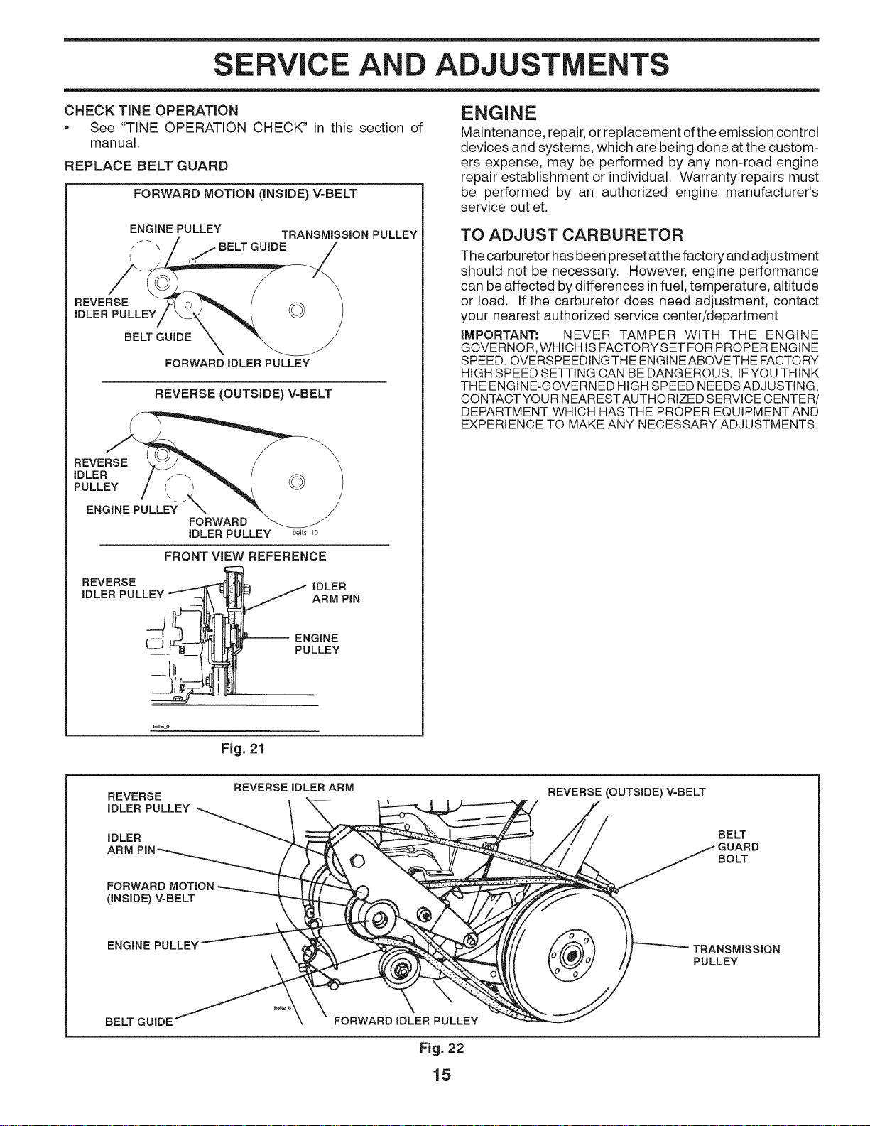
TO REPLACE V=BELTS (See Figs. 21 and 22)
Replace V-belts if they have stretched considerably or if
they show cracks or frayed edges. There are two (2) V-belts
-forward (inside) and reverse (outside).
Belt guard must be removed to service belts. See "TO
REMOVE BELT GUARD" in this section of manual.
NOTE: Observe carefully routing of both belts and location
of all belt guides before removing belts.
BELT REMOVAL
• Remove reverse idler pulley from idler arm.
• Remove reverse (outside) V-belt.
• Remove forward (inside) V-belt from transmission pulley
first and then from engine pulley.
BELT REPLACEMENT
• Install new forward (inside) V-belt to engine pulley first
then to transmission pulley. Be sure belt is positioned
on inside groove of both pulleys, inside all belt guides
and rests on idler pulley.
• Before installing reverse (outside) V-belt, turn belt"inside
out". Twist so wide, flat surface of belt is to inside.
• Wrap V-belt around reverse idler pulley and reassemble
idler to idler arm. Tighten securely. Be sure belt is
between reverse idler pulley and idler arm pin.
• Install belt to outside groove oftransmission pulley. Be
sure belt is inside all belt guides and rests on outside
groove of engine pulley.
SERVICE AND ADJUSTMENTS
CHECK TINE OPERATION
• See "TINE OPERATION CHECK" in this section of
manual.
REPLACE BELT GUARD
FORWARD MOTION (iNSiDE) V-BELT
ENGINE PULLEY
TRANSMISSION PULLEY
/ I _ \ BELT GUIDE
REVERSE
IDLER PULLEY
BELT GUIDE
FORWARD IDLER PULLEY
REVERSE (OUTSIDE) V-BELT
REVERSE
IDLER
PULLEY I /
\
ENGINE PULLEYX
FORWARD
iDLER PULLEY
belts 10
FRONT VIEW REFERENCE
REVERSE _ iDLER
ENGINE
Maintenance, repair, or replacement of the emission control
devices and systems, which are being done at the custom-
ers expense, may be performed by any non-road engine
repair establishment or individual. Warranty repairs must
be performed by an authorized engine manufacturer's
service outlet.
TO ADJUST CARBURETOR
The carburetor has been preset atthe factory and adjustment
should not be necessary. However, engine performance
can be affected by differences in fuel, temperature, altitude
or load. If the carburetor does need adjustment, contact
your nearest authorized service center/department
IMPORTANT: NEVER TAMPER WITH THE ENGINE
GOVERNOR, WHICH IS FACTORYSET FOR PROPER ENGINE
SPEED. OVERSPEEDINGTHE ENGINEABOVETHE FACTORY
HIGH SPEED SETTING CAN BE DANGEROUS. IFYOU THINK
THE ENGINE-GOVERNED HIGH SPEED NEEDS ADJUSTING,
CONTACTYOUR NEARESTAUTHORIZED SERVICE CENTER/
DEPARTMENT, WHICH HAS THE PROPER EQUIPMENT AND
EXPERIENCE TO MAKE ANY NECESSARY ADJUSTMENTS.
Fig. 21
REVERSE
IDLER PULLEY
IDLER
ARM
FORWARD
(iNSIDE) V=BELT
REVERSEIDLER ARM
REVERSE (OUTSIDE) V-BELT
BELT
GUARD
BOLT
ENGINE PULLEY
TRANSMISSION
PULLEY
BELT GUIDE FORWARD IDLER PULLEY
Fig. 22
15
STORAGE
Immediately prepare your tiller for storage at the end of the
season or if the unit will not be used for 30 days or more.
WARNING: Never store the tiller with
gasoline in the tank inside a building
where fumes may reach an open flame
or spark. AIIowthe engine to cool before
storing in any enclosure.
TILLER
• Clean entire tiller (See "CLEANING" in the Maintenance
section of this manual).
• Inspect and replace belts, if necessary (See belt re-
placement instructionsinthe Service and Adjustments
section of this manual).
• Lubricate as shown in the Maintenance section of this
manual.
• Be sure that all nuts, bolts and screws are securely
fastened. Inspect moving parts for damage, breakage
and wear. Replace if necessary.
• Touch up all rusted or chipped paint surfaces; sand
lightly before painting.
ENGINE
FUEL SYSTEM
iMPORTANT: IT IS IMPORTANTTO PREVENT GUM DEPOSITS
FROM FORMING IN ESSENTIAL FUEL SYSTEM PARTS SUCH
AS THE CARBURETOR, FUEL FILTER, FUEL HOSE, OR TANK
DURING STORAGE. ALSO, EXPERIENCE INDICATES THAT
ALCOHOL BLENDED FUELS (CALLED GASOHOL OR USING
ETHANOL OR METHANOL) CAN ATTRACT MOISTURE WHICH
LEADS TO SEPARATION AND FORMATION OFACIDS DURING
STORAGE. ACIDIC GAS CAN DAMAGE THE FUEL SYSTEM
OF AN ENGINE WHILE IN STORAGE.
• Drain the fuel tank.
• Start the engine and let it run until the fuel lines and
carburetor are empty.
• Never use engine or carburetor cleaner products in the
fuel tank or permanent.
NOTE: Fuel stablizer is an acceptable alternative in
minimizing the formation of fuel gum deposits during
storage. Add stabilizer to gasoline in fuel tank or storage
container. Always follow the mix ratio found on stablizer
container. Run engine at least 10 minutes after adding
stablizer to allow the stabilizer to reach the carburetor.
Do not drain the gas tank and carburetor ifusing fuel
stabilizer.
ENGINE OiL
Drain oil (with enginewarm) and replacewith clean oil. (See
"ENGINE" in the Maintenance section of this manual).
CYLINDER(S)
• Remove spark plug.
• Pour 1 ounce (29 ml) of oil through spark plug hole
into cylinder.
• Pull starter handle slowly several times to distribute
oil.
• Replace with new spark plug.
OTHER
• Do not store gasoline from one season to another.
• Replace your gasoline can if your can starts to rust.
Rust and/or dirt in your gasoline will cause problems.
• Ifpossible, store your unit indoors and cover it to give
protection from dust and dirt.
• Cover your unit with a suitable protective cover that
does not retain moisture. Do not use plastic. Plastic
cannot breathe which allows condensation to form and
will cause your unit to rust.
IMPORTANT: NEVER COVER TILLER WHILE ENGINE AND
EXHAUSTAREAS ARE STILL WARM.
16

TROUBLESHOOTING POINTS
PROBLEM CAUSE CORRECTION
Will not start
Hard to start
Loss of power
Engine overheats
Excessive bounce/
difficult handling
Soil bails up or clumps
Engine runs but tiller
won't move
Engine runs but labors
when tilling
1. Out of fuel.
2. Engine not "CHOKED" properly.
3. Engine flooded.
4. Dirty air cleaner.
5. Water in fuel.
6. Clogged fuel tank.
7. Loose spark plug wire.
8. Bad spark plug or improper gap.
9. Carburetor out of adjustment.
1. Throttle control not set properly.
2. Dirty air cleaner.
3. Bad spark plug or improper gap.
4. Stale or dirty fuel.
5. Loose spark plug wire.
6. Carburetor out of adjustment.
1. Engine is overloaded.
2. Dirty air cleaner.
3. Low oil level/dirty oil.
4. Faulty spark plug.
5. Oil in fuel.
6. Stale or dirty fuel.
7. Water in fuel.
8. Clogged fuel tank.
9. Spark plug wire loose.
10. Dirty engine air screen.
11. Dirty/clogged muffler.
12. Carburetor out of adjustment.
13. Poor compression.
1. Low oil level/dirty oil.
2. Dirty engine air screen.
3. Dirty engine.
4. Partially plugged muffler.
5. Improper carburetor adjustment.
1. Ground too dry and hard.
2. Wheels and depth stake incorrectly adjusted.
1. Ground too wet.
1. Tine control is not engaged.
2. V-belt not correctly adjusted.
3. V-belt is off pulley(s).
1. Tilling too deep.
2. Throttle control not properly adjusted.
3. Carburetor out of adjustment.
1. Fill fuel tank.
2. See "TO START ENGINE" in the Operation section.
3. Wait several minutes before attempting to start.
4. Clean or replace air cleaner cartridge.
5. Drain fuel tank and carburetor, and refill tank with fresh
gasoline.
6. Remove fuel tank and clean.
7. Make sure spark plug wire is seated properly on plug.
8. Replace spark plug or adjust gap.
9. Make necessary adjustments.
1. Place throttle control in "FAST" position.
2. Clean or replace air cleaner cartridge.
3. Replace spark plug or adjust gap.
4. Drain fuel tank and refill with fresh gasoline.
5. Make sure spark plug wire is seated properly on plug.
6. Make necessary adjustments.
1. Set depth stake and wheels for shallower tilling.
2. Clean or replace air cleaner cartridge.
3. Check oil level/change oil.
4. Clean and regap or change spark plug.
5. Drain and clean fuel tank and refill, and clean carburetor.
6. Drain fuel tank and refill with fresh gasoline.
7. Drain fuel tank and carburetor, and refill tank with fresh
gasoline.
8. Remove fuel tank and clean.
9. Connect and tighten spark plug wire.
10. Clean engine airscreen.
11. Clean/replace muffler.
12. Make necessary adjustments.
13. Contact an authorized service center/department.
1. Check oil level/change oil.
2. Clean engine air screen.
3. Clean cylinder fins, air screen, muffler area.
4. Remove and clean muffler.
5. Adjust carburetor to richer position.
1. Moisten ground or wait for more favorable soil
conditions.
2. Adjust wheels and depth stake.
1. Wait for more favorable soil conditions.
1. Engage tine control.
2. Inspect/adjust V-belt.
3. Inspect V-belt.
1. Set depth stake for shallower tilling.
2. Check throttle control setting.
3. Make necessary adjustments.
17
REPAIR PARTS
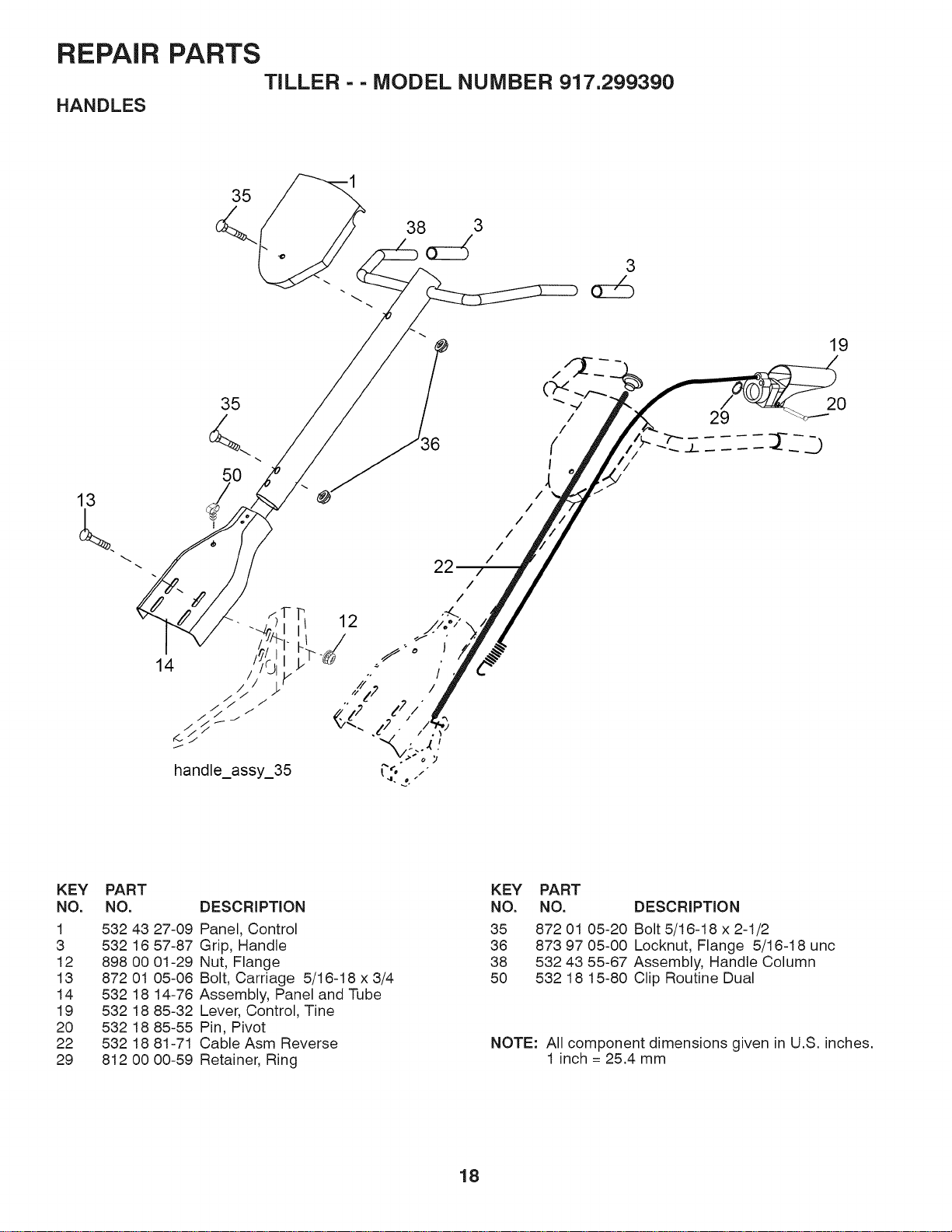
HANDLES
TILLER - - MODEL NUMBER 917.299390
35
38 3
3
35
50
/
/
/
/
/
/
/
29
19
20
KEY
NO.
1
3
12
13
14
19
2O
22
29
PART
NO.
532 43
532 16
898 00
872 01
532 18
532 18
532 18
532 18
812 00
DESCRiPTiON
27-09 Panel, Control
57-87 Grip, HandJe
01-29 Nut, Flange
05-08 Bolt, Carriage 5/18-18 x 3/4
14-78 Assembly, Panel and Tube
85-32 Lever, Control, Tine
85-55 Pin, Pivot
81-71 Cable Asm Reverse
00-59 Retainer, Ring
KEY
NO.
35
38
38
5O
PART
NO. DESCRiPTiON
872 01 05-20 Bolt 5/18-18 x 2-1/2
873 97 05-00 Locknut, Flange 5/18-18 unc
532 43 55-87 Assembly, Handle Column
532 18 15-80 Clip Routine Dual
NOTE: All component dimensions given in U.S. inches.
1 inch = 25.4 mm
18
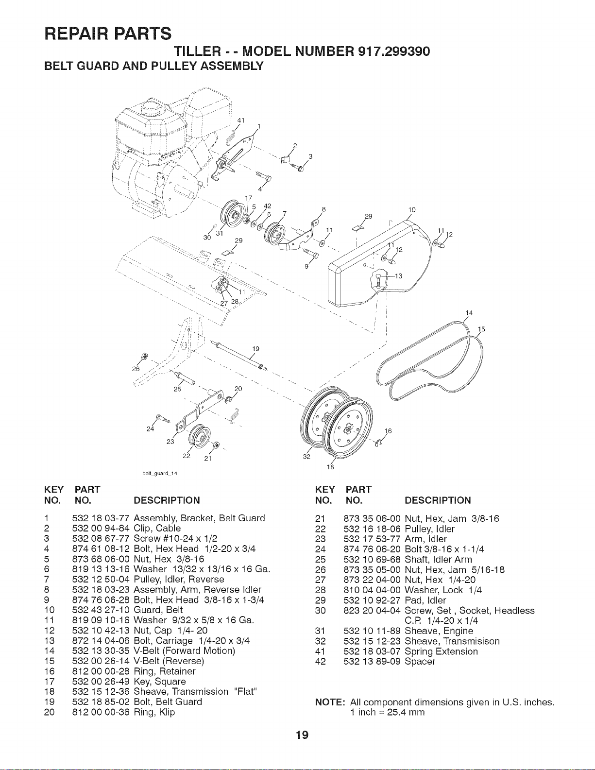
REPAIR PARTS
TILLER - - MODEL NUMBER 917.299390
BELT GUARD AND PULLEY ASSEMBLY
KEY PART
NO. NO.
1 532 18 03-77
2 532 00 94-84
3 532 08 67-77
4 874 61 08-12
5 873 68 06-00
6 819 13 13-16
7 532 12 50-04
8 532 18 03-23
9 874 76 06-28
10 532 43 27-10
11 8190910-16
12 532 10 42-13
13 872 14 04-06
14 532 13 30-35
15 532 00 26-14
16 812 00 00-28
17 532 00 26-49
18 532 15 12-36
19 532 18 85-02
20 812 00 00-36
41
24
23
/
22 21
belt guard 14
DESCRiPTiON
Assembly, Bracket, Belt Guard
Clip, Cable
Screw #10-24 x 1/2
Bolt, Hex Head 1/2-20 x 3/4
Nut, Hex 3/8-16
Washer 13/32 x 13/16 x 16 Ga.
Pulley, Idler, Reverse
Assembly, Arm, Reverse Idler
Bolt, Hex Head 3/8-16 x 1-3/4
Guard, Belt
Washer 9/32 x 5/8 x 16 Ga.
Nut, Cap 1/4- 20
Bolt, Carriage 1/4-20 x 3/4
V-Belt (Forward Motion)
V-Belt (Reverse)
Ring, Retainer
Key, Square
Sheave, Transmission "Flat"
Bolt, Belt Guard
Ring, Klip
lO
112
32
18
KEY PART
NO. NO.
21 873 35
22 532 16
23 532 17
24 874 76
25 532 10
26 873 35
27 873 22
28 810 04
29 532 10
30 823 20
31 532 10
32 532 15
41 532 18
42 532 13
14
15
16
DESCRiPTiON
06-00 Nut, Hex, Jam 3/8-16
18-06 Pulley, Idler
53-77 Arm, Idler
06-20 Bolt 3/8-16 x 1-1/4
69-68 Shaft, Idler Arm
05-00 Nut, Hex, Jam 5/16-18
04-00 Nut, Hex 1/4-20
04-00 Washer, Lock 1/4
92-27 Pad, Idler
04-04 Screw, Set, Socket, Headless
C.R 1/4-20 x 1/4
11-89 Sheave, Engine
12-23 Sheave, Transmisison
03-07 Spring Extension
89-09 Spacer
NOTE: All component dimensions given in U.S. inches.
1 inch = 25.4 mm
19
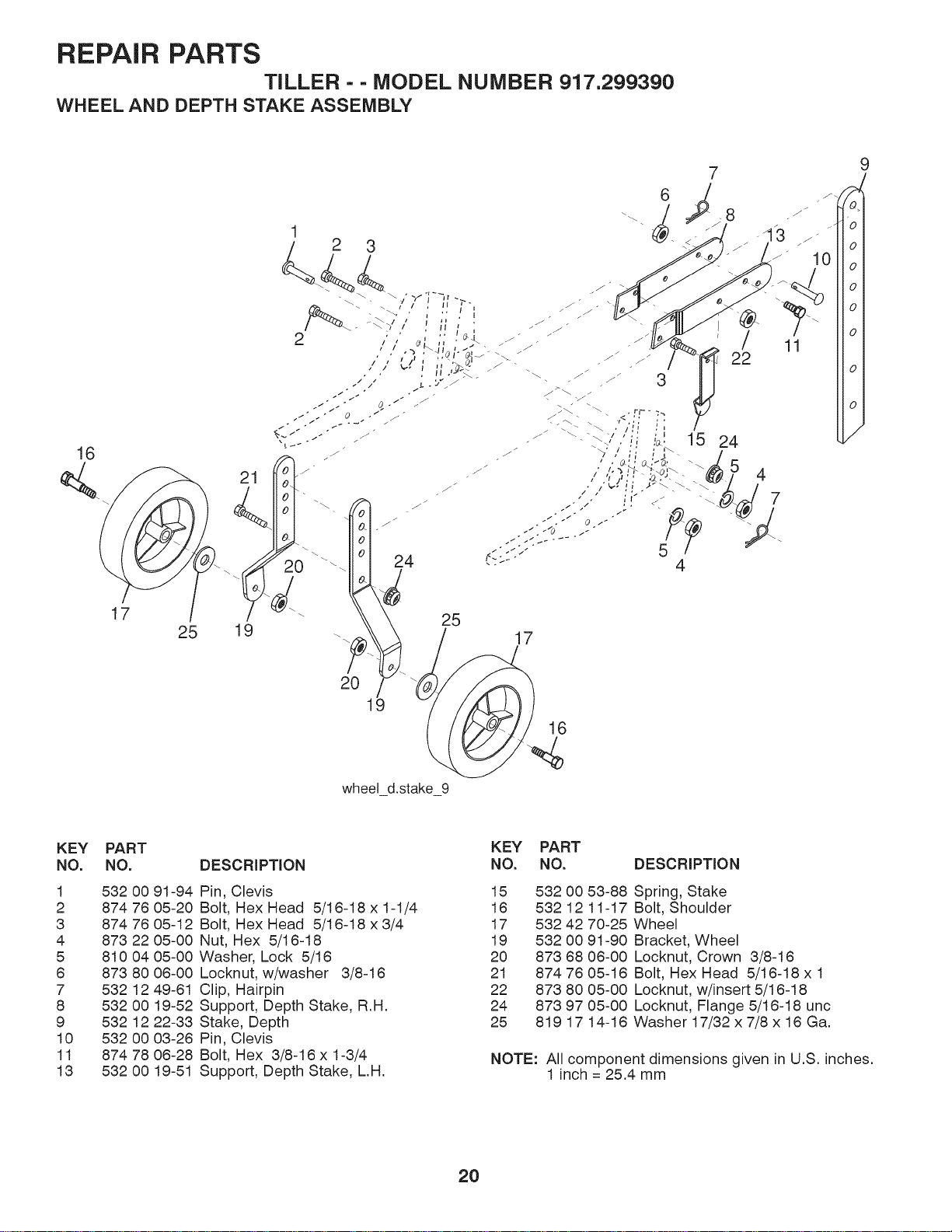
REPAIR PARTS
TILLER - - MODEL NUMBER 917.299390
WHEEL AND DEPTH STAKE ASSEMBLY
16
25
KEY PART
NO. NO.
1 532 O0 91-94
2 874 76 05-20
3 874 76 05-12
4 873 22 05-00
5 810 04 05-00
6 873 80 06-00
7 532 12 49-61
8 532 O0 19-52
9 532 12 22-33
10 532 O0 03-26
11 874 78 06-28
13 532 O0 19-51
KEY PART
DESCRIPTION NO. NO. DESCRIPTION
Pin, Clevis 15 532 00
Bolt, Hex Head 5/16-18 x 1-1/4 16 532 12
Bolt, Hex Head 5/16-18 x 3/4 17 532 42
Nut, Hex 5/16-18 19 532 00
Washer, Lock 5/16 20 873 68
Locknut, w/washer 3/8-16 21 874 76
Clip, Hairpin 22 873 80
Support, Depth Stake, R.H. 24 873 97
Stake, Depth 25 819 17
Pin, Clevis
Bolt, Hex 3/8-16 x 1-3/4
Support, Depth Stake, L.H.
53-88 Spring, Stake
11-17 Bolt, Shoulder
70-25 Wheel
91-90 Bracket, Wheel
06-00 Locknut, Crown 3/8-16
05-16 Bolt, Hex Head 5/16-18 x 1
05-00 Locknut, w/insert 5/16-18
05-00 Locknut, Flange 5/16-18 unc
14-16 Washer 17/32 x 7/8 x 16 Ga.
NOTE: All component dimensions given in U.S. inches.
1 inch = 25.4 mm
2O
REPAIR PARTS
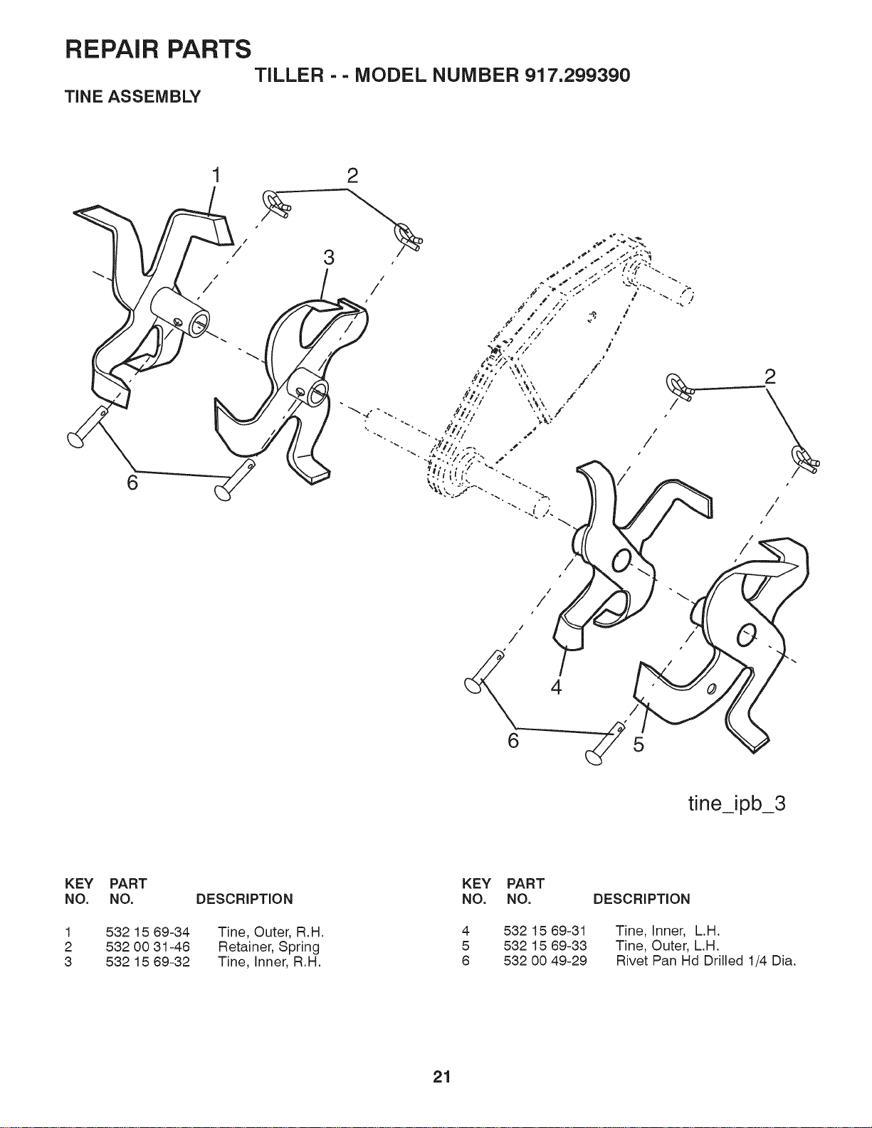
TINE ASSEMBLY
TILLER - - MODEL NUMBER 917.299390
6
2
5
/
/
/
tine_ipb_3
KEY PART
NO, NO, DESCRIPTION
1 532 15 69-34 Tine, Outer, R.H.
2 532 00 31-46 Retainer, Spring
3 532 15 69-32 Tine, Inner, R.H.
KEY PART
NO. NO.
4 532 15 69-31
5 532 15 69-33
6 532 00 49-29
DESCRIPTION
Tine, Inner, L.H.
Tine, Outer, L.H.
Rivet Pan Hd Drilled 1/4 Dia.
21

REPAIR PARTS
TRANSMiSSiON
TILLER - - MODEL NUMBER 917.299390
2i
/
11
11
lO
14
10
KEY PART
NO. NO.
1 874 76 05-24
2 874 78 06-52
3 819 13 13-11
5 873 90 06-00
8 532 43 27-11
7 532 18 81-95
8 532 16 58-34
10 873 97 05-00
11 532 18 79-12
12 532 15 12-22
12
DESCRiPTiON
Bolt, Hex 5/16-18 x 1-1/2 Gr. 2
Bolt, Hex 3/8-18 x 3-1/4
Washer 13/32 x 13/18 x 11
Locknut 3/8-16
Shield, Tine
Bracket, Engine, R.H.
Bracket, Engine, L.H.
Nut, Hex 5/16-18
Bolt, Hex Head 5/16-18 x 2.5
Transmission
KEY
NO.
14
18
17
18
19
2O
10
transmission 12
PART
NO. DESCRIPTION
532 00 91-73 Spacer, Split
819 09 14-12 Washer 9/32 x 7/8 x 12 Ga.
819 09 20-18 Washer 9/32x 1-1/4 x 18 Ga.
810 04 04-00 Washer, Lock 1/4
874 61 04-12 Bolt, Hex 1/4-28 x 3/4 Gr. 5
Engine Bnggs Model 121002-1380-B8
NOTE: All component dimensions given in U.S. inches.
1 inch = 25.4 mm
22
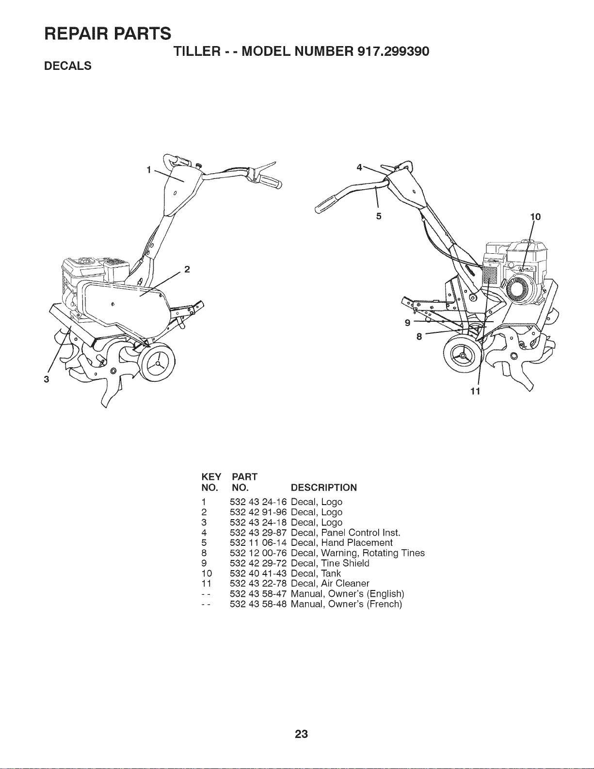
REPAIR PARTS
DECALS
TILLER - - MODEL NUMBER 917.299390
3
9
8
10
11
KEY PART
NO. NO.
1 532 43 24-16
2 532 42 91-96
3 532 43 24-18
4 532 43 29-87
5 532 11 08-14
8 532 12 00-76
9 532 42 29-72
10 532 40 41-43
11 532 43 22-78
- - 532 43 58-47
- - 532 43 58-48
DESCRiPTiON
Decal. Logo
Decal. Logo
Decal. Logo
Decal. Panel Control Inst.
Decal. Hand Placement
Decal. Warning, Rotating Tines
Decal. Tine Shield
Decal. Tank
Decal. Air Cleaner
Manual, Owner's (English)
Manual, Owner's (French)
23
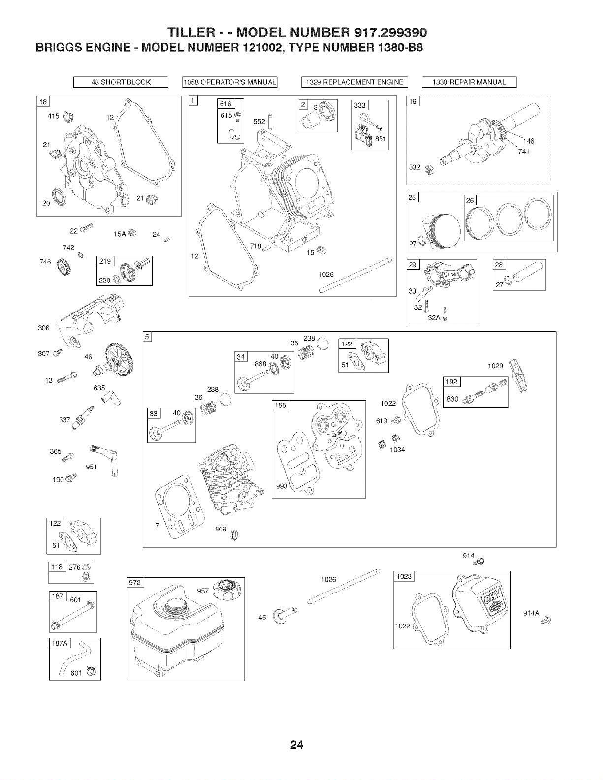
TILLER - - MODEL NUMBER 917.299390
BRIGGS ENGINE - MODEL NUMBER 121002, TYPE NUMBER 1380-B8
J 48 SHORT BLOCK ]
415 _ 12
22
742
_3
746 _
21@
15A _ 24
0
[_0_O_OR'SM_NU_L][I_2_R_L_C_M_N_NG,N_]I I_0_RM_NU_LI
11
lS_
1026
332
146
741
13 _¢:_
46
365_
951
190@__
635
1029
)
869
601
45 _k_j"
1026 ........S_ ......
1022
914A
24
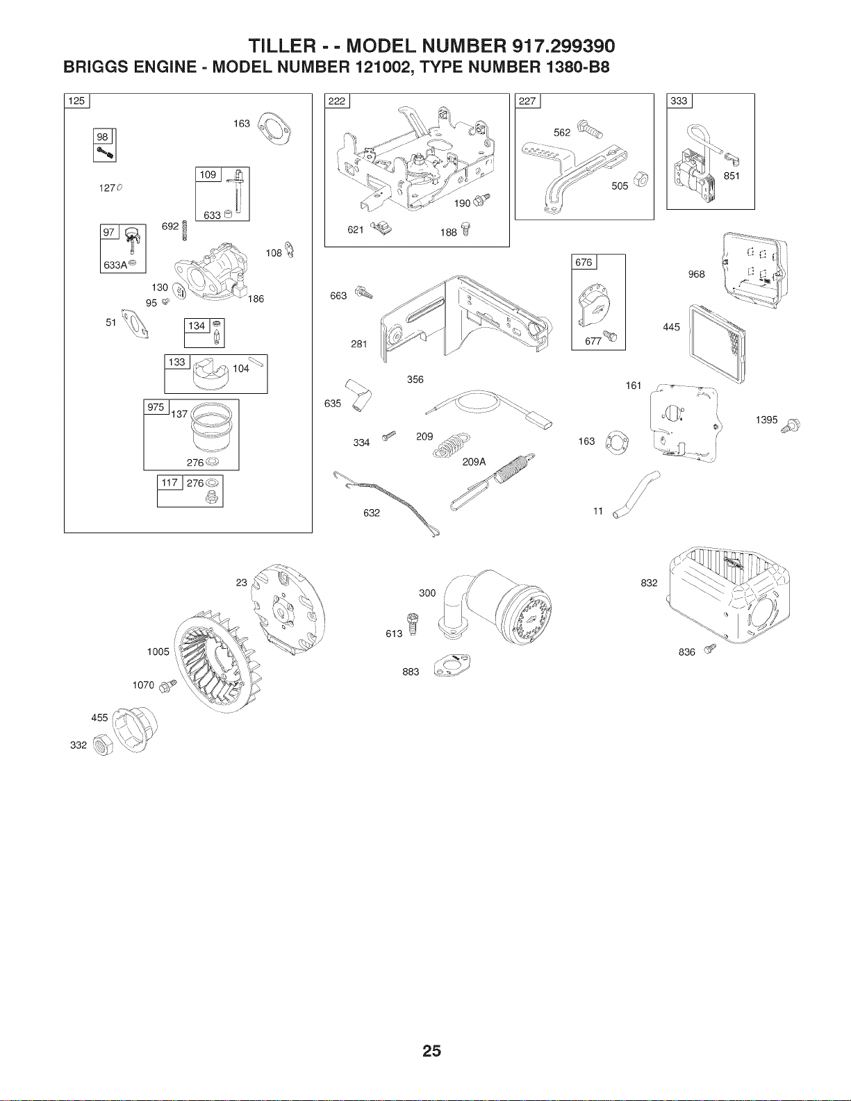
TILLER - - MODEL NUMBER 917.299390
BRIGGS ENGINE - MODEL NUMBER 121002, TYPE NUMBER 1380-B8
1270
163
6921
130 ' '\ %" _'"
95 _'_ q'£ "_186
51_i\
11331_._._ "
_%
276 _'-"_/
621
663 (_¢'%
281
190_
188
562 _,_
J 677 _
635
334 ''2_
356
163
161
445
•,,S_• •_ ..... _
o_l,.o
1005
1070 _,_
455
332-_
23
300
613
883
832
836 _'_
25
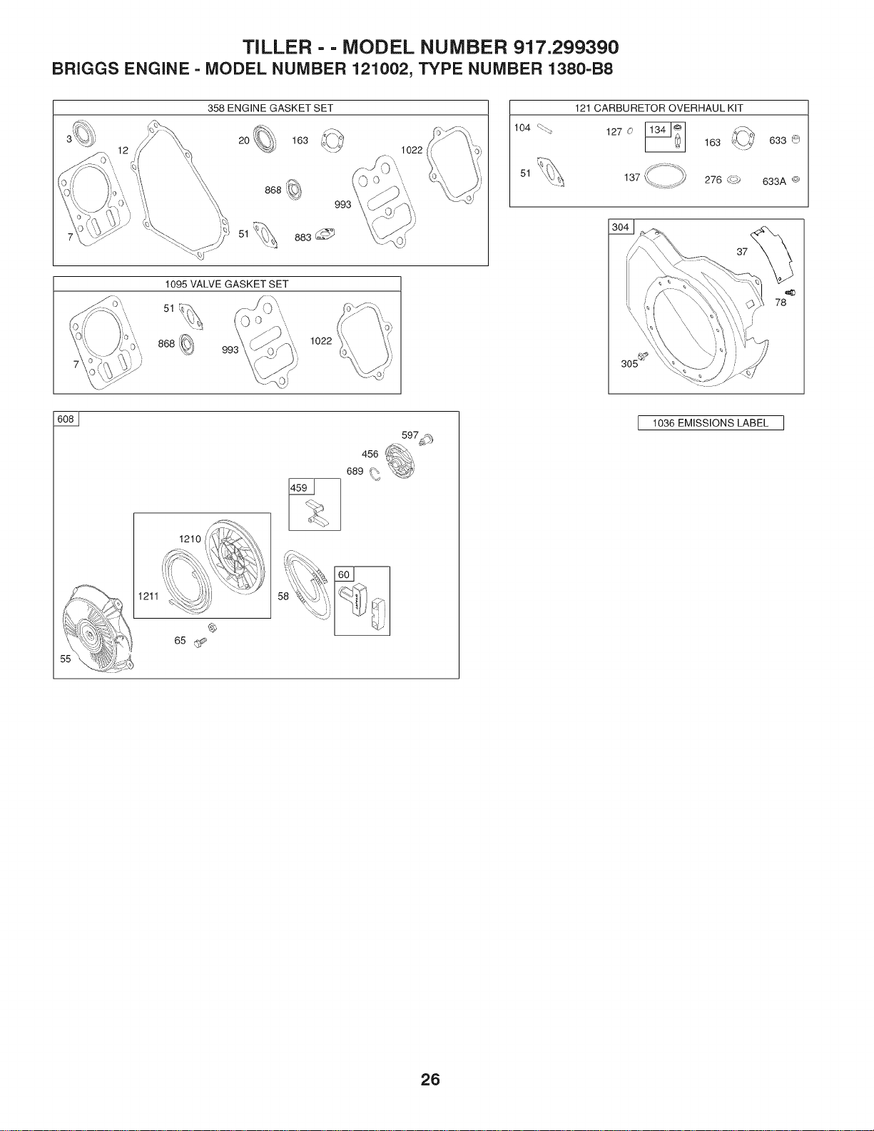
TILLER - - MODEL NUMBER 917.299390
BRIGGS ENGINE - MODEL NUMBER 121002, TYPE NUMBER 1380-B8
358 ENGINE GASKET SET
20 163
51 883_
1022
1022
104 _%
51
121 CARBURETOR OVERHAUL KIT
127 0
163
633 _)
137 276 63j 633A @
1211
1210 I
65
456
689 (%
%j,
597_
I 1036 EMISSIONS LABEL ]
26

TILLER - - MODEL NUMBER 917.299390
BRIGGS ENGINE = MODEL NUMBER 121002, TYPE NUMBER 1380=B8
KEY PART KEY PART
NO. NO. DESCRIPTION NO. NO.
1 699510 Cylinder Assembly 161 790631
2 399269 Kit-Bushing/Seal (Magneto Side) 163 696024
3 299819s Seal-Oil (Magneto Side) 186 692317
5 797439 Head-Cylinder 187 791766
7 698210 Gasket-Cylinder Head 187A 791867
11 790632 Tube-Breather 188 699479
12 699485 Gasket-Crankcase 190 699220
13 699482 Screw (Cylinder Head) 192 797440
15 691686 Plug-Oil Drain 209 691278
15A 691682 Plug-Oil Drain 209 692571
16 797070 Crankshaft 219 693578
18 699696 Cover-Crankcase 220 691724
20 692550 Seal-Oil (PTO Side) 222 793107
21 281658s Cap-Oil Fill 227 794367
22 699478 Screw (Crankcase Cover/Sump) 238 691300
23 699488 Flywheel 265 691024
24 222698s Key-Flywheel 267 699492
25 795429 Piston Assembly (Standard) 276 271716
795430 Piston Assembly (.020" Oversize) 281 793122
26 791969 Ring Set (Standard) 300 693593
793001 Ring Set (.020" Oversize) 304 699598
27 691866 Lock-Piston Pin 305 699480
28 499423 Pin-Piston 306 795334
29 690124 Rod-Connecting 307 699483
30 791584 Dipper-Connecting Rod 332 792723
32 691664 Screw (Connecting Rod) (Short) 333 796964
32A 695759 Screw (Connecting Rod) (Long) 334 699477
33 499642 Valve-Exhaust 337 491055s
34 795443 Valve-I ntake 356 692390
35 691304 Spring-Valve (Intake) 358 791797
36 691304 Spring-Valve (Exhaust) 365 699484
37 699661 Guard-Flywheel 415 693463
40 692194 Retainer-Valve 445 491588s
45 690977 Tappet-Valve 455 692591
46 693404 Camshaft 456 692299
48 791518 Short Block 459 281505s
51 692555 Gasket-Intake 505 691251
55 791848 Housing-Rewind Starter 552 692346
58 693389 Rope-Starter 562 691119
60 490652 Grip-Starter Rope 597 691696
65 699228 Screw (Rewind Starter) 601 791850
95 691636 Screw (Throttle Valve) 608 795930
97 690024 Shaft-Throttle 613 699209
98 398185 Kit-Idle Speed 615 692576
104 691242 Pin-Float Hinge 616 692547
108 692567 Valve-Choke 619 699230
109 790624 Shaft-Choke 621 692310
117 690048 Jet-Main (Standard) 632 693408
118 497315 Jet-Main (High Altitude) 633 693867
121 792006 Kit-Carburetor Overhaul
122 795643 Spacer-Carburetor 633A 691321
125 698474 Carburetor
127 691739 Plug-Welch 635 692076
130 691181 Vatve-Th rottte 663 699206
133 398187 Float-Carburetor 676 796596
134 398188 Kit-Needle/Seat 677 699203
137 693981 Gasket-Float Bowl 689 691855
146 690979 Key-Timing 692 690572
155 797442 Plate-Cylinder Head 718 690959
DESCRIPTION
Base-Air Cleaner
Gasket-Air Cleaner
Hose-Connector
Line-Fuel (Cut to Required Length)
Line-Fuel (Formed)
Screw (Control Bracket)
Screw (Fuel Tank)
Adjuster-Rocker Arm
Spring-Governor (Platinum)
Spring-Governor (# 5 Hole)
Gear-Governor
Washer (Governor Gear)
Bracket-Control
Lever-Governor Control
Cap-Valve
Clamp-Casing
Screw (Casing Clamp)
Washer-Sealing
Panel-Control
Muffter
Housing-Blower
Screw (Blower Housing)
Shield-Cylinder
Screw (Cylinder Shield)
Nut (Flywheel)
Armature-Magneto
Screw (Magneto Armature)
Plug-Spark
Wire-Stop
Gasket Set-Engine
Screw (Carburetor)
Plug (Crankcase Cover)
Filter-Air Cleaner Cartridge
Cup-Flywheel
Plate-Pawt Friction
Pawt-Ratchet
Nut (Governor Control Lever)
Bushing-Governor Crank
Bolt (Governor Control Lever)
Screw (Pawt Friction Plate)
Clamp-Hose (Green)
Starter-Rewind
Screw (Muffler)
Retainer-Governor Shaft
Crank-Governor
Screw (Cylinder Head Plate)
Switch-Stop (Brake)
Spring/Link-M echanical Governor
Seal-Choke/Throttle Shaft (Choke
Shaft)
Seal-Choke/Throttle Shaft (Throttle
Shaft)
Boot-Spark Plug
Screw (Control Panel)
Deflector-Muffler
Screw (Muffler Deflector)
Spring-Friction
Spring-Detent
Pin-Locating
27

TILLER - - MODEL NUMBER 917.299390
BRIGGS ENGINE - MODEL NUMBER 121002, TYPE NUMBER 1380-B8
KEY PART
NO. NO. DESCRIPTION
741 695087 Gear-Timing
742 692564 Retainer-E Ring
746 790278 Gear-Idler
830 797441 Stud-Rocker Arm
832 693583 Guard-Muffler
836 699632 Screw (Muffler Guard)
851 493880s Terminal-Spark Plug
868 795440 Seal-Valve
869 691115 Seat-Valve
883 691893 Gasket-Exhaust
914 699480 Screw (Rocker Cover) (Bottom)
914A 797444 Screw (Rocker Cover)
951 790630 Lever-Choke
957 795027 Cap-Fuel Tank
958 698180 Valve-Fuel Shut Off
968 791082 Cover-Air Cleaner
972 697779 Tank-Fuel
975 790559 Bowl-Fuel
993 694088 Gasket-Cylinder Head Plate
1005 692592 Fan-Flywheel
1022 691890 Gasket-Rocker Cover
1023 499924 Cover-Rocker
1026 790287 Rod-Push
1029 797443 Arm-Rocker
1034 691343 Guide-Push Rod
1036 Label-Emissions (Available from a
Briggs & Stratton Authorized Dealer)
1058 277040 Operator's Manual
1070 699201 Screw (Flywheel Fan)
1095 791798 Gasket Set-Valve
1210 791849 Pulley/Spring Assembly (Pulley)
1211 791849 Pulley/Spring Assembly (Spring)
1329 122002-
0520-B8 Replacement Engine
1330 276781 Repair Manual
1395 690370 Screw (Air Cleaner Base)
NOTE: All component dimensions given in U.S. inches.
1 inch = 25.4 mm
28

SERVICE OTES
29

SERVICE NOTES
3O

SERVICE OTES
31
o
o3
I'o
ob
o
©
F
Z
{::
:3
®
-O
cL
..._"
(1)
C
b_
2,
Husqvams" WARRANTY STATEMENT
SECTION1: LIMITEDWARRANTY
HusqvarnaForest &Garden Company ("Husqvarna")warrants Husqvarnaproductto the original purchaser to be free from
defects in material andworkmanship from the date of purchase for the "Warranty Period" ofthe product as set forthbelow:
Lifetime Warranty (Parts and Labor): All tillertines and trimmer shafts against breakage. Proof of purchase required.
Lifetime Warranty ("PARTS ONLY" after initial warranty expiration): Ignition coilsand modules on handheld product.
Proofof purchase required.
WARRANTY SCHEDULE FOR TURFCARE Equipment -Zero Turn Riders
(New warranty appliesto units sold afterAugust 1,2005. Also appliesto units factory-equipped with R.O.P.S.
EZ Zero Turn Riders: 3 year consumer warrantyor 600 hours ofuse (when used solelyat the owner's residence.)
EZ & MZ Zero Turn Riders: 1year commercial warranty or 600hours of use.
iZ, LZ & BZ Zero Turn Riders: 5 year consumer warrantyor 1,500hoursof use.
iZ, LZ & BZ Zero Turn Riders: 5 year commercial warranty or 1,500 hoursof use.
3 Year or 1,500Hour Commercial Use Warranty: spindleson zero turn riders, hydraulicpumpsand wheel motors.
Warranty Schedule forTurf Care Walk Behind Units- W, WG & WHZero Turn Riders- 3 year consumer and commercial
warranty. New warrantyapplies to units sold afterAugust 1,2005. Also appliesto units factory-equippedwith R.O.RS.
2 Year COMMERCIAL and CONSUMERWarranty: all Husqvama ground-engaging commercialequipment.
WARRANTY SCHEDULE FOR CONSUMERTURF CARE EQUIPMENT:
2 Year Consumer Warranty: Automatic mower,all Residential Zero Turn Riders,all lawn,yard andgarden tractors, all
noncommercial walk behind mowers, tillers,snow blowers,electrical productsand power-assist collectionsystems for
noncommercial, nonprofessional,noninstitutionalor nonincome producing use, exceptas hereinstated.All consumer
product use musthave been limitedto the owner's residence.
WARRANTY SCHEDULE FORCONSUMER FOREST & GARDENEQUIPMENT:
2 Year Consumer Warranty: all consumerchain saws,trimmers, brushcutters, clearing saws, handheld blowers, backpack
blowers, hedgetrimmers, and electrical productsfor noncommercial,nonprofessional, noninstitutionalor nonincome
producing use, except as hereinstated.All consumer productuse must have been limited tothe owner's residence.
2 Year or 2,000 Hour Powertrain & 1Year or 1,000Hour Body Warranty: HusqvarnaUtility Vehicles.
1 Year Warranty: Power cutters, stump grinder, pole prunersand pole saws for non-commercial, non-professional,
noninstitutional, non-municipalityor non-income producing use.All 300 seriestrimmers, brushcutters, clearingsaws,
hovering trimmers,stick edgers, backpack blowers, hand held blowers, hedge trimmers,power-assistcollection systemsfor
commercial, institutional, professional or income producing purposes or use.
1 Year Conditional Component Warranty: Chain saw crankshaftsfor commercial/professional use (parts and labor).Saw
mustbe operated with HusqvarnaXP 2 cycle oil.
90 Day Commercial Warranty: Automatic mower,chain saws, 100 seriestrimmers,power cutters,stump grinders,pole
saws, pole pruners,snow throwers, model series580& 600 walk-behindmowers, or anyHusqvarnaproduct usedfor
commercial, institutional,professional, municipalityor income producingpurposes or useexceptas otherwise providedherein.
Batteries: 1 year prorated limited warrantywith 100% replacementduring the first 6 months.
Rental Warranty: 90 dayson all applicableprofessional equipment referencewarranty time period charts
located in the backof the Retailer Warranty Policy& Procedure Manual.
Husqvarna Safety Apparel carries a 90-day warrantyfrom the date of the customer's original purchasefor defects in
material andworkmanship. Normalwear, tear or abuse is notcovered underwarranty. Product mustbe returnedto Charlotte
with a warrantyclaim form. Allcare and maintenanceinstructions must be followed asstated by the manufacturer on the
care label.The fit ofthe protectiveapparel/boot is not covered under warranty.
30 Day Warranty: Replacement parts,accessories including bars and chains,tools anddisplay items.Emission control
system components necessary to complywith CARB-TIER II and EPAregulations,except for those components which are
partof engine systems manufactured bythird part engine manufacturersfor which the purchaser has received a separate
warranty with product attime of purchase.
SECTION2: HUSQVARNA'SOBLIGATIONS UNDERTHE WARRANTY
Husqvarna will repairor replace defectivecomponents withoutcharge for parts or labor ifa component fails becauseof a
defect in material orworkmanship during the warrantyperiod.
SECTION3: ITEMS NOT COVEREDBYTHIS WARRANTY
The following items are not covered by thiswarranty:
(1) Normalcustomer maintenance itemswhich becomeworn through normal regular use, including, but not limited to, belts,
blades, blade adapters,bulbs, clutches, clutch drums, filters, guide bars, lubricants, rewind springs,saw chain,spark plugs,
starter ropes andtiller tines;
(2) Naturaldiscoloration of material due to ultraviolet light;
(3) Engine anddrive systems not manufactured by Husqvarna; these items are covered by the respective manufacturer's
warranty as provided in writing withthe product information supplied atthe time ofpurchase; all claims mustbesent to the
appropriate manufacturer;
(4) Lawn andgarden attachments arecovered by a third party which givesa warranty, all claimsfor warrantyshould be sent
to the manufacturer,
(5)Commercial or consumer mowingdecks with sand abrasiondamage.
(6) Emission ControlSystem components necessary to complywith CARB-TIER II and EPAregulations which are
manufactured by third party engine manufacturer.
SECTION4: EXCEPTIONSAND LIMITATIONS
This warranty shall be inapplicableto defects resulting from the following:
(1)Accident, abuse, misuse, negligence and neglect,including stale fuel, dirt, abrasives, moisture, rust,corrosion, or any
adverse reactiondue to incorrectstorage or use habits;
(2) Failureto operate or maintain the unit in accordancewith the Owner's/Operator's manual or instruction sheetfurnished
by Husqvarna;
(3)Alterations or modificationsthat change the intendeduse of the productor affectsthe product's performance,operation,
safety,or durability,or causesthe productto fail to comply with any applicable laws; or:
(4)Additional damage to parts or components due to continueduse occurring after any ofthe above.
REPAIROR REPLACEMENTAS PROVIDED UNDERTHIS WARRANTY iS THE EXCLUSIVE REMEDY OF THE
PURCHASER. HUSQVARNASHALL NOT BE LIABLE FOR ANY INCIDENTALOR CONSEQUENTIALDAMAGES FOR
BREACHOF ANY EXPRESS OR IMPLIEDWARRANTY ON THESE PRODUCTS EXCEPTTO THE EXTENT
PROHIBITED BYAPPLICABLELAW. ANY IMPLIEDWARRANTY OF MERCHANTABILITYOR FITNESS FORA
PARTICULARPURPOSE ONTHESE PRODUCTS IS LIMITEDIN DURATIONTO THE WARRANTY PERIODAS
DEFINED INTHE LIMITED WARRANTY STATEMENT.HUSQVARNARESERVES THE RIGHT TO CHANGEOR
IMPROVE THE DESIGNOF THE PRODUCT WITHOUT NOTICE,AND DOES NOTASSUME OBLIGATION TO UPDATE
PREVIOUSLYMANUFACTURED PRODUCTS.
Some states do not allowthe exclusion of incidentalor consequential damages, or limitations onhow long an implied
warranty lasts, so the above limitations or exclusionsmay not apply to you. This warrantygives you specificlegal rights,and
you may also haveother rights whichvary from state to state.
SECTION5: CUSTOMERRESPONSIBILITIES
The product mustexhibit reasonable care, maintenance,operation,storage andgeneral upkeep as written in the
maintenancesection ofthe Owner's/Operator's manual. Should anoperational problem or failure occur,the product should
not be used, but delivered as is to an authorizedHusqvarna retailerfor evaluation. Proofof purchase, as explainedin
section 6, restssolely with the customer.
SECTION6: PROCEDURETO OBTAIN WARRANTYCONSIDERATION
Itis the Owner's and Retailer's responsibilityto make certain thatthe Warranty RegistrationCardis properly filled out and
mailed to HusqvarnaForest &Garden Company.This card should be mailed within ten (10)days from the date of purchase
in orderto confirm the warrantyand tofacilitate post-sale service.
Proofof purchase must be presentedto the authorized Husqvarna retailerin orderto obtain warrantyservice. This proof
mustinclude date purchased,model number,serial number,andcomplete nameand address ofthe selling retailer.
Toobtain the benefit ofthis warranty, the product believedto be defective mustbe deliveredto an authorizedHusqvarna
retailerin a timely manner, no laterthan thirty (30) days from date ofthe operational problemor failure.The product must be
deliveredat the owner's expense. Downtime,pick-up and delivery charges are notcovered by this warranty. An authorized
Husqvama retailer can be normally locatedthrough the "Yellow Pages"ofthe localtelephone directory or by calling 1-800-
HUSKY62for a retailerin your area.
HUSQVARNA
7349 StatesvilleRoad
Charlotte, NC 28269 2008