Loading ...
Loading ...
Loading ...
SIERV CE A DADJUSTMENTS
, ,i.., ,............................................
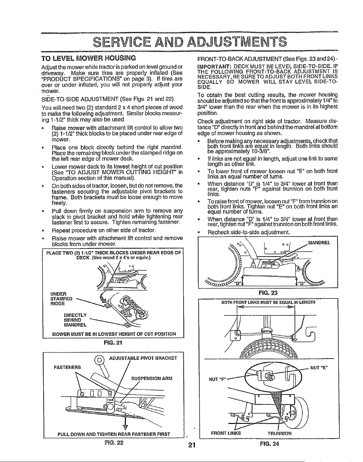
TO LEVEL MOWER HOUSING
Adjust the mower while tractor isparked on level ground or
driveway. Make sure tires are properly inflated (See
"PRODUCT SPECIFICATIONS" on page 3). If tires are
over or under inflated, you will not propedy adjust your
mower.
si[)E..TO*SIDE ADJUSTMENT (See Figs. 21 and 22)
You will need two (2) standard 2 x 4 short pieces of wood
to make the following adjustmenL Similar blocks measur-
ing 1-1/2" thick may also be used,
o Raise mower with attachment lift control to allow two
(2) 1-1/2" thick blocks to be placed under rear edge of
mower,
° Place one block directly beh|nd the right mandrel,,
Place the remaining block under the stamped ridge on
the left rear edge of mower deck.
• Lower mower deck to its lowest height of cut position
(See "TO ADJUST MOWER CUTTING HEIGHT" in
Operation section of this manual),
o On both sides of tractor, loosen, but do not remove, the
fasteners securing the adjustable pivot brackets to
frame. Both brackets must be {oose enough to move
freely.
o Pull down firmly on suspension arm to remove any
slack in pivot bracket and hold while tightening rear
fastener first to secure. Tighten remalnHngfastener.
o Repeat procedure on other side of tractor.
• Raise mower with attachment li_ control and remove
blocks from under mower,
PLACE TWO {2) t-1/2" THICK BLOCKS UNDER REAR EDGE OF
DECK (Use wood 2 x 4*s or equ_w)
¢
STAMPED
RIDGE
DIRECTLY
BEHIND _"
MANDREL
MOWER MUST BE IN LOWEST HEIGHT OF CUT POSITION
FIG. 21
ADJUSTABLE PWOT BRACKET
FASTENERS
SUSPENSION ARM
PULL DOWNANDTIGHTEN REAR FASTENERFIRST
F6G, 22
FRONT-TO-BACK ADJUSTMENT (See Figs. 23 and 24) -
IMPORTANT: DECK MUST BE LEVEL SIDE-TO-SIDE. IF
THE FOLLOWING FRONT-TO-BACK ADJUSTMENT IS
NECESSARY, BE SURE TO ADJUST BOTH FRONT LINKS
EQUALLY SO MOWER WILL STAY LEVEL SIDE-TO o
SIDEo
"[o obtain the best cutting results, the mower housing
should be adjusted so that the front is approximately 1/4" to
3/4" lower than the rear when the mower is in its highest
position.
Check adjustment on right side of tractor'. Measure dis-
tance "D" directly in front and behind the mandrel at bottom
edge of mower housing as shown.
o Bef0re ma!dng any necessar7 adjustments_ chec,kthat
DmnTron[links are equal in leng[n. #o_n i_nlcssnoula
be approximately I0-3/8".
• If links are not _qual in length, adjust one link to same
length as other }ink_
o To lower front of mower loosen nut "E" on both front
links an equal number of turns,
. When distance "D" is 1/4" to 3/4" lower at front than
rear, tighten nuts "F" against trunnion on both front
links.
• To raise front of mower, loosen nut"F" from trunnion on
both front I!nks. Tighten nut "E" on both front links an
equal number of turnso
o When distance "D" is 1/4" to 3/4" lower at front than
rear, tighten nut"F" against trunnion on both front links.
o Recheck side4o*side adjustment.
MANDREL
FIG, 23
BOTH FRONT LINKS MUST BE EQUAL IN LENGTH
21
FRONTLINKS
FIG. 24
Loading ...
Loading ...
Loading ...