Loading ...
Loading ...
Loading ...
9
BEFORE EACH USE
• Always ensure that the mower is in a safe working condition. Inspect the cutter blade for damage; check safety
devices and guards; check that all nuts, bolts and screws are secure.
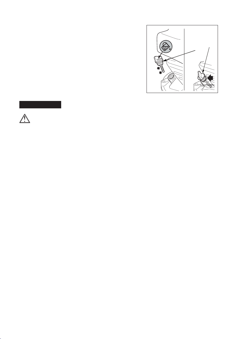
• Check the oil level as follows:
a) Remove the oil ller cap and wipe the dipstick clean (Figure 7).
b) Ret the dipstick into the ller neck without screwing it down.
Remove the dipstick and check the oil level; oil should be at the FULL
mark. The oil tank capacity is about 0,5 litre or 20 uid oz.
c) If the oil level is low add Mounteld oil part number MX855 or a
SAE 30 oil, to the upper limit on the dipstick. Do not overll; the
oil level should not be above the FULL mark.
• Fill the fuel tank with unleaded petrol. Do not overll, there is no need
to ll tank to the top. The fuel tank need only contain enough fuel to
complete the days mowing. If you run out of fuel, relling must only be
carried out once the engine has cooled. Fuel stored within the machine
for 28 days or more can go stale and should be drained before further
use.
MAINTENANCE
Stop the engine and disconnect the spark plug lead before working on the machine.
DO NOT TIP THE MOWER ONTO ITS SIDE AS THIS WILL FLOOD THE AIR FILTER WITH OIL.
To access the underside of the machine, lift the front wheels by lowering the handle until it rests on the ground.
CUTTER BLADE
Examine the cutter blade regularly for wear or damage.
• A slightly worn blade can be re-sharpened by your local authorised Mounteld dealer
• If the blade is damaged it should be replaced. Replacement blade kits are available from your Mounteld stockist.
The part number for the blade kit is MS1199. If in doubt refer to your authorised Mounteld dealer, or telephone
0800 121 6585 or
1800 806 149 ROI
Blade must always be marked with part number GGP 81004360/3.
ENGINE
An engine Manufacturer’s Owner’s Manual is supplied with your mower. Please read this, it provides detailed
information on engine operation, maintenance and battery care. Repair work other than routine maintenance, should
be carried out by an authorised Mounteld dealer.
STORAGE
A little time spent on your mower after use will ensure many years of reliable mowing.
To access the underside of the cutter deck, ensure that the spark plug lead is disconnected. Then lift the front wheels
by lowering the handle until it rests on the ground. Do not tip the mower onto its side as this will ood the air lter
with oil. Failure to maintain and care for your engine may invalidate the machine guarantee. Please see the guarantee
statement for full terms and conditions.
AFTER EACH USE
• Remove any grass pulp from the underside of the cutter deck using a non-metallic instrument such as a piece of
wood. Take care not to damage the paintwork.
• Examine the cutter blade for any damage. A damaged blade may upset the balance of your mower and cause
excessive vibration. If in doubt refer to your authorised Mounteld dealer.
• Inspect the grass collector and clean it if necessary. If the mesh becomes clogged airow will be reduced and impair
grass collection.
• The handle can be folded down to reduce the amount of storage space required. Take care not to trap any of the
operating cables when folding or unfolding the handle.
• Store the mower in a clean, dry area well away from any naked ames, sparks or heat source.
LONG TERM - (if you are not using your mower for more than 28 days)
• Give the machine a thorough clean, paying particular attention to the underside.
• Lubricate all moving parts
• Empty the fuel tank either by running the mower out of fuel or tip the machine backwards and onto the back left wheel to
drain the fuel into a suitable container. To drain the carburettor it is necessary to slacken the drain screw. The drain screw
is situated under the carburettor on the oat bowl (see diagram page 4). A bolt holds the bowl in place on the very bottom,
but on an angle slighlty closer to you is another bolt with a red washer. This is the drain screw.
MAX
MIN
Figure 7
OIL FILLER CAP/
DIPSTICK
Loading ...
Loading ...
Loading ...