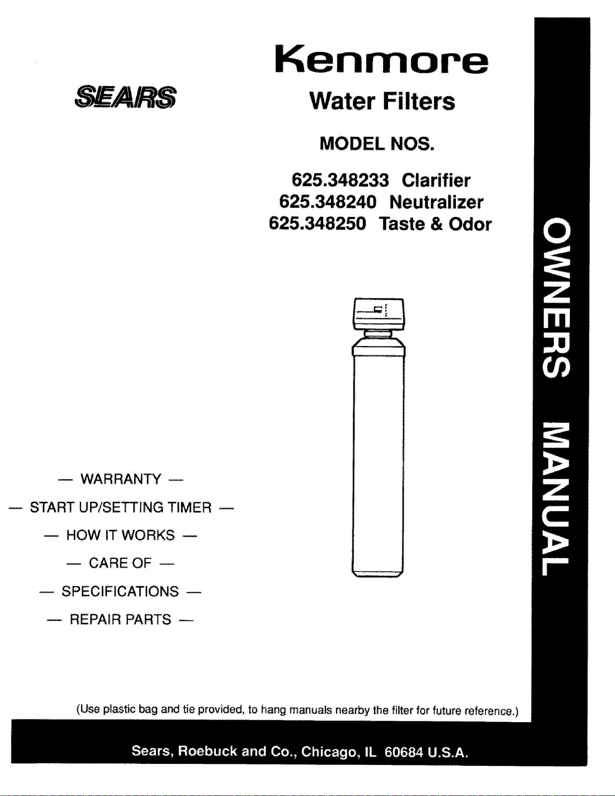
MODEL NOS.
Taste & Odor
m WARRAN_
START UP/SETTING TIMER
u HOW IT WORKS w
CARE OF
m SPECIFICATIONS
REPAIR PARTS
(Use plastic bag and tie provided, to hang manuals nearby the filter for future reference,)
I!1 ] IIIIIII
[ i
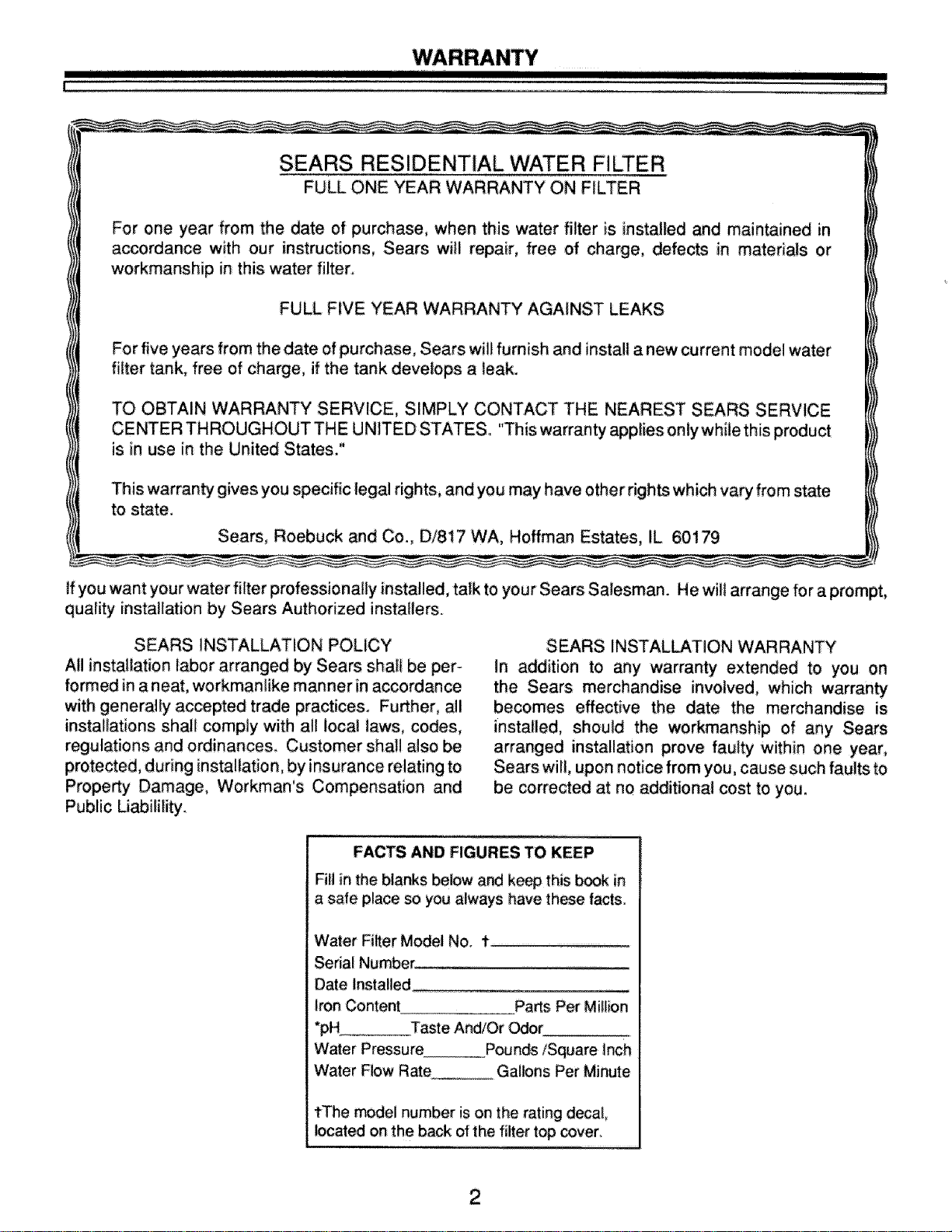
SEARS RESIDENTIAL WATER FILTER
FULL ONE YEAR WARRANTY ON FILTER
For one year from the date of purchase, when this water filter is installed and maintained in
accordance with our instructions, Sears witl repair, free of charge, defects in materials or
workmanship in this water filter.
FULL FIVE YEAR WARRANTY AGAINST LEAKS
For five years from the date of purchase, Sears will furnish and install a new current model water
filter tank, free of charge, if the tank develops a leak.
TO OBTAIN WARRANTY SERVICE, SIMPLY CONTACT THE NEAREST SEARS SERVICE
CENTER THROUGHOUT THE UNITED STATES. "This warranty applies only while this product
is in use in the United States."
This warranty gives you specific legal rights, and you may have other rights which vary fro m state
to state.
Sears, Roebuck and Co., D/817 WA, Hoffman Estates, IL 60179
If you want your water filter professionally installed, talk to your Sears Salesman. He wilt arrange for a prompt,
quality installation by Sears Authorized installers.
SEARS INSTALLATION POLICY
All installation labor arranged by Sears shall be per-
formed in a neat, workmanlike manner in accordance
with generally accepted trade practice& Fu_her, all
installations shall comply with all local laws, codes,
regulations and ordinances. Customer shall also be
protected, during installation, by insurance relating to
Prope_y Damage, Workman's Compensation and
Public Liabilility.
SEARS INSTALLATION WARRANTY
In addition to any warranty extended to you on
the Sears merchandise involved, which warranty
becomes effective the date the merchandise is
installed, should the workmanship of any Sews
arranged installation prove faulty within one year,
Sears will, upon notice from you, cause such faults to
be corrected at no additional cost to you.
FACTS AND FIGURES TO KEEP
Fill in the blanks below and keep this book in
a safe place so you always have these facts.
Water Filter Model No. 1"
Serial Number ............................................
Date Installed
Iron Content Parts Per Million
*PH Taste And/Or _r
Water Pressure Pounds/Square inch
Water Flow Rate Gallons Per Minute
tThe _de! number is on the rating decal,
_cated on the back of the filter top cover.
TABLE OF CONTENTS
IIIIIIII II I
L
SECTION 1 FILTER START UP
A. SAFEW GUIDES
B_ CHECK LiST OF STEP-BY-STEP GUIDES TO INSTALL
C, SANITIZING THE WATER FILTER
D. PROGRAM THE TIMER
4
5
6
7_8
SECTION 2 HOW YOUR WATER FILTER WORKS
Am FACE PLATE TIMER FEATURES 9-10
B. FILTER APPL_CATIONS 11
C. FILTERED WATER SERVICE, AND BACKWASH 12
SECTION 3 CARE OF YOUR FILTER
A_ KEEP THE FILTER FROM FREEZING
B, ADDING MINERAL _.. NEUTRALIZER FILTER
C. REPLACING MINERAL... TASTE & ODOR FILTER
D. HELPFUL HINTS CHECKLIST
13
14-!5
16
17
SECTION 4 OTHER THINGS TO KNOW
A_ DIMENSIONS/SPECIFICATiONS
t8
SECTION 5
A, ELECTRICAL CONNECTIONS
B, BACKWASH CYCLE TIMES
C. DIAGNOSTICS
D. "QUICK_CHECK" TROUBLESHOOTING
E, ROTARY VALVE SERVICE
E WATER FLOW THROUGH THE FILTER VALVE
SERVICER'S TECH INFORMATION
19
20
21
22
23
24
SECTION 6
REPAIR PARTS
25-27
3
I I IIIIIIHIIIIIIIIIIIH_HI [ Illll 1!
1A.
& Read all steps, guides and rules carefully
before installing and using your new water filter.
Followall steps exactly to correctly instalL Fail-
ure to follow them could cause personal injury
or property damage. Reading this bookwill also
help you to get all of the benefits from your water
filter.
A Your water filter will improve your water as
described on page i 1, It will not _ften water or
remove iron_ !t will not purify polluted wa_r or
make it safe to drink. Also me the specifications
on page 18,
A Prot_t the filter and piping from fr_zing,
Damage from freezing voids the filter warranty,
See page 13.
!l
PLEASE READ AND COMPLY WITH THE
TO
DAMAGE TO
PROPERTY, PERSONAL INJURY, OR POS-
SIBLE FATAL SHOCK.
A THiS FILTER WORKS ON 24 VOLTS ONLY,
BE SURE TO USE THE TRANSFORMER !N-
CLUDED_ AND PLUG IT INTO A 120V OUTLET,
A Unplug the transformer right away if the
power cable _ouid _me da_ or frayed.
_ke repairs before plugging back into the
power outlet.
A Always unplug the filter from electrical
power before removing outer valve covers_
4
1 WATER FILTER START-UP
I ........... IH[TIIIII I
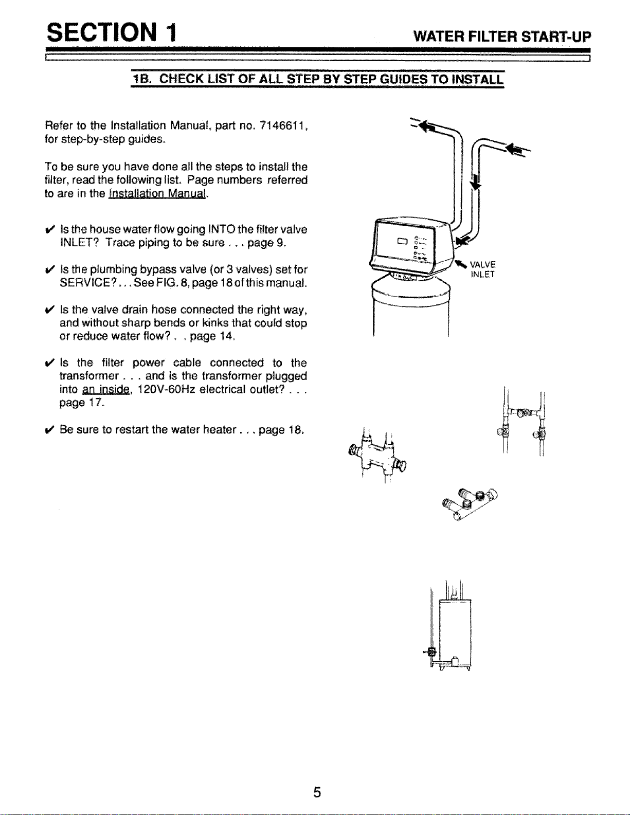
lB. CHECK LIST OF ALL STEP BY STEP GUIDES TO INSTALL
Refer to the Installation Manuat, part no. 7146611,
for step-by-step guides.
To be sure you have done all the steps to install the
_ter, read the following list, Page numbers referred
to are in the Installation Manual,
is the house water flow going INTO the filter valve
INLET? Trace piping to be sure,,, page 9,
it" Is the plumbing bypass valve (or 3 valves) set for
SERVICE?, _.See FIG, 8, page 18of this manual.
_/ Is the va{ve drain hose connected the right way,
and without sharp bends or kinks that could stop
or reduce water flow?, , page 14,
V Is the filter power c_!e connected to the
transformer.., and is the transformer plugged
into anJnside, 120V-60Hz electrical outlet?...
page 17.
V Be sure to resta_ the water heater.,, page 18,
VALVE
INLET
5
i
WATER FILTER START-UP
!
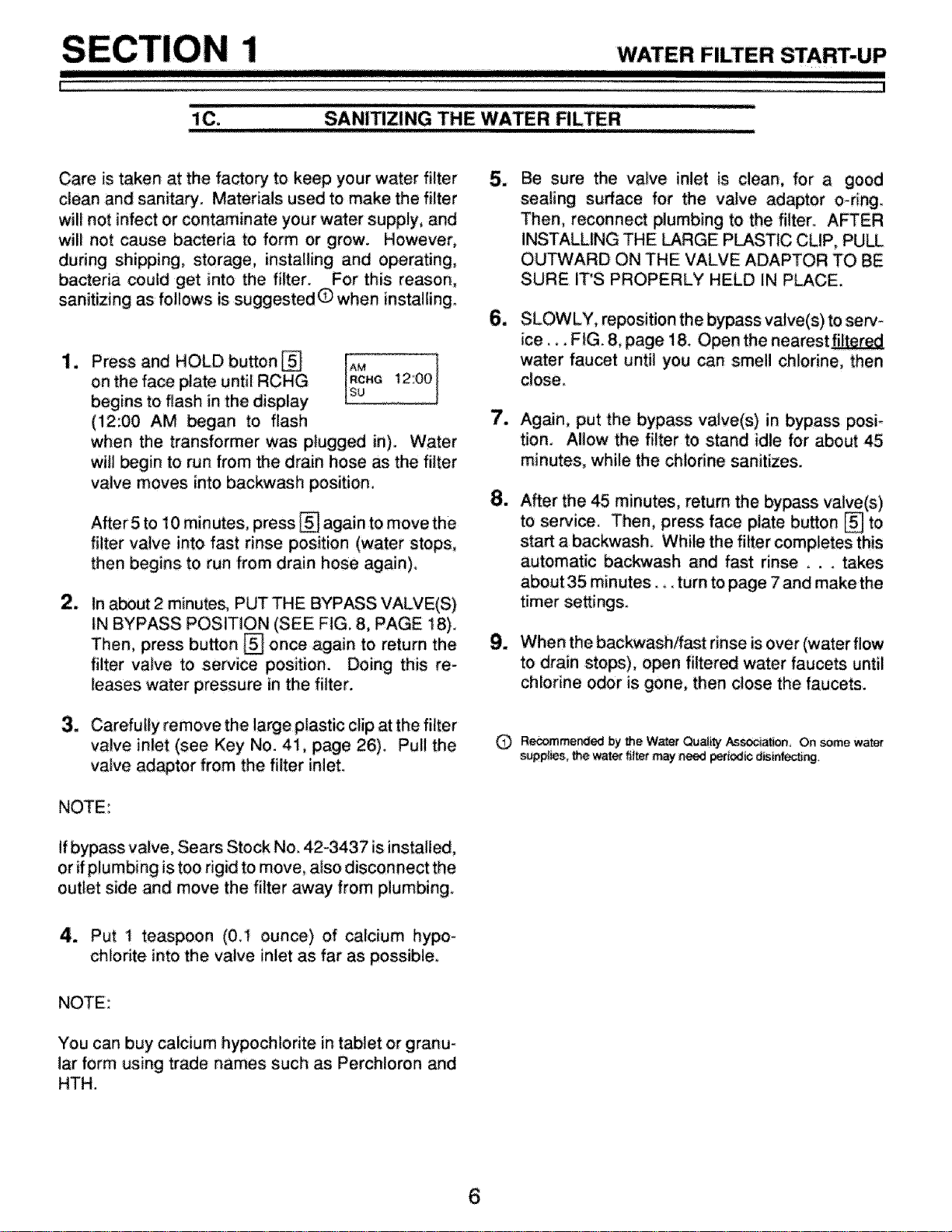
1C. SANITIZING THE WATER FILTER
rrrrrrgg]mrr W,
Care is taken at the factory" to keep your water filter
clean and sanitary. Materials used to make the filter
will not infect or contaminate your water supply, and
will not cause bacteria to form or grow. However,
during shipping, _orage, installing and operating,
bacteria could get into the filter. For this reason,
sanitizing as follows is suggestedO when installing.
lm
2_
Pres,ondHOLObo.on, iIAo 1
on the face plate until RCHG RCM_12:00
begins to flash in the display Lsu
(12;00 AM began to flash
when the transformer was plugged in). Water
will begin to run from the drain hose _ the filter
valve moves into backwash position.
After 5 to 10 minutes, press [] again to move the
filter valve into fast rinse position (water stops,
then begins to run from drain hose again),
In a_ut 2 minutes, PUT THE BYPASS VALVE(S)
IN BYPASS POSITION (SEE FIG. 8, PAGE 18).
Then, press button [] once again to return the
filter valve to service position. Doing this re-
leases water pressure in the filter.
3. Carefully remove the large plastic clip at the filter
valve inlet (see Key No. 41, page 26). Pull:the
vatve adaptor from the filter inlet.
NOTE:
If bypass valve, Sears Stock No. 42-3437 isinstalled,
or ifplumbing is too rigid to move, also disconnect the
outlet side and; move the filter away from plumbing.
5_
6_
7_
8_
Be sure the valve inlet is clean, for a good
sealing surface for the valve adaptor o-ring.
Then, reconnect plumbing to the filter. AFTER
iNSTALLING THE LARGE PLASTIC CLIP, PULL
OUTWARD ON THE VALVE ADAPTOR TO BE
SURE IT'S PROPERLY HELD IN PLACE_
SLOW LY, reposition the bypass valve(s) tosew_
ice... FIG. 8, page 18. Open the nearest_
water faucet until you can smell chlorine, then
close
Again, put the bypass valve(s) in bypass posi-
tion. Allow the filter to stand idle for about 45
minutes, while the chlorine sanitizes.
After the 45 minutes, return the bypass valve(s)
to service. Then, press face plate button [] to
start a backwash While the filter completes this
automatic backwash and fast rinse _.. takes
about 35 minutes.., turn to page 7 and make the
timer settings.
When the bact_wash/fast rinse is over (water flow
to drain stops), open filtered water faucets until
chlorine odor is gone, then close the faucets_
Recornmended by _e Water Qu_ity Aspirin, On some water
supplies, the water _iter may need periodio disintec_ng,
4. Put 1 teaspoon (0.! ounce) of calcium hypoo
chlorite into the valve inlet as far as possible.
NOTE:
You can buy calcium hypochlorite in tablet or granu-
lar form using trade names such as Perchloron and
HTH.
6
WATER FILTER START-UP
I I!1[ IIIIIIIIIIIIIIIIIIII
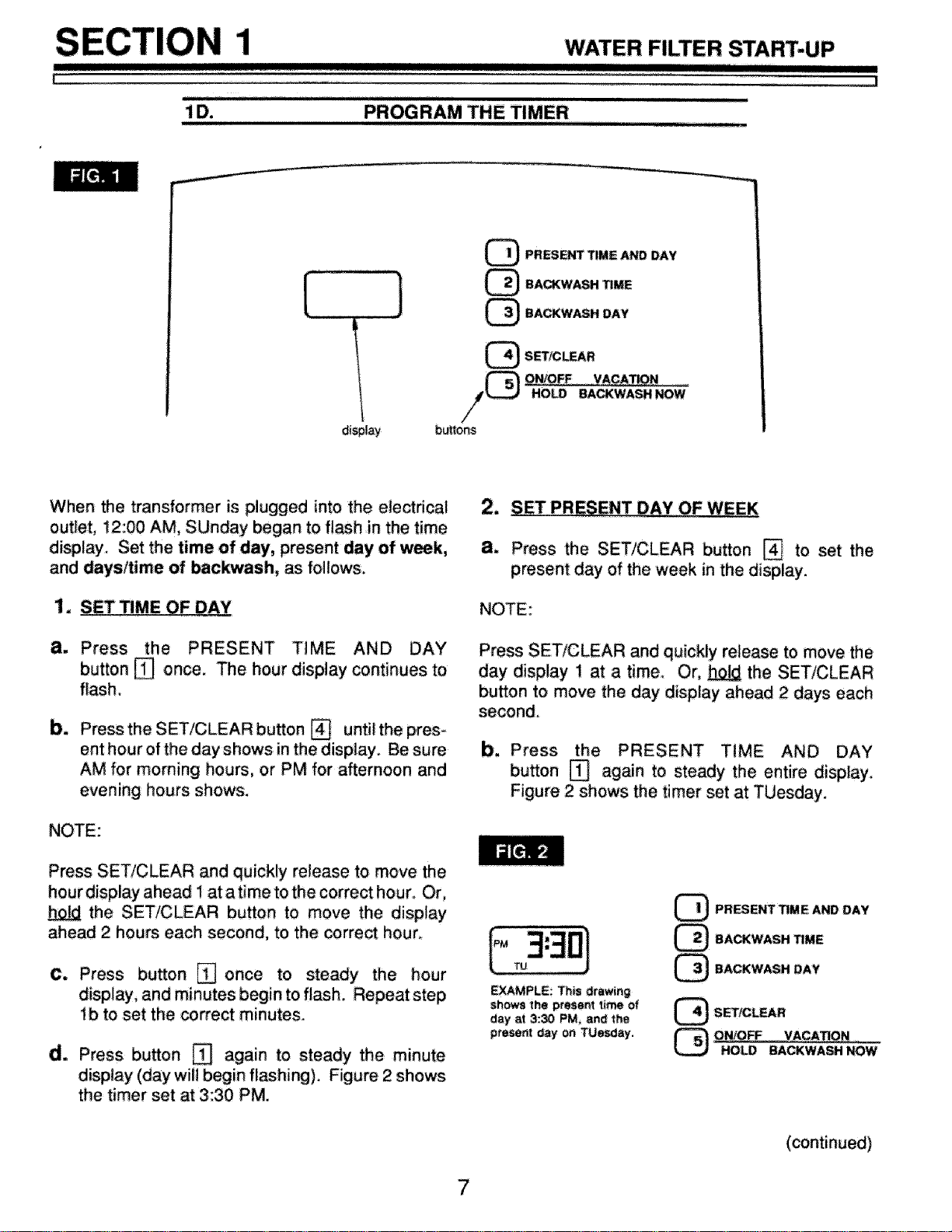
PROGRAM THE TIMER
JJ ......................................
display
buttOnS
Q PRESENT TIME AND DAY
_ BA_WASH _ME
_ BACKWASH DAY
_ SET/CL_R
QN/OFF VA_TI_ ......
HO_ BACKWASH NOW
When the transformer is plugged into the electdca!
outlet, t2:00 AM, SUnday began to fl_h in the time
display. Set the time of day, present day of week,
and days/time of backwash, _ follows.
1. SET TIME OF DAY
a. Press the PRESENT TiME AND DAY
button [] once. The hour display continues to
flash
b_
Press the SET/CLEAR button [] until the pres-
ent hour of the day shows in the display. Be sure
AM for morning hours, or PM for afternoon and
evening hours shows.
NOTE:
Press SET/CLEAR and quickly release to move the
hourdisplay ahead I at atime to the correct hour. Or,
the SET/CLEAR button to move the display
ahead 2 hours each second, to the correct hour_
C. Press button [] once to steady the hour
display, and minutes begin to flash. Repeat step
ib to set the correct minutes.
d. Press button _ again to steady the minute
display (day will begin fishing). Figure 2 shows
the timer set at 3:30 PM.
2, SET PRESENT DAY,OF WEEK
a. Press the SET/CLEAR button _ to set the
present day of the week in the display.
NOTE:
Press SET/CLEAR and quickly release to move the
day display 1 at a time. Or, _ the SET/CLEAR
button to move the day display ahead 2 days each
second.
b. Press the TiME AND DAY
button [] again to steady the entire display.
Figure 2 shows the timer set at TUesday.
EXAMPLE: Th_s drawing
shows the present time of
day at 3:30 PM, and the
present day OnTUesday,
PRESENT TIME AND DAY
(_) BACKWASH TIME
_ BACKWASH DAY
_ SET/CLEAR
_ ON/OFF VACATION
HOLD BACKWASH NOW
(continued)

HOW YOUR WATER FILTER WORKS
I1_111111111 I I1!III
]
' "FA EP' LA _ '........
C TE TIMER FEATURES,..........
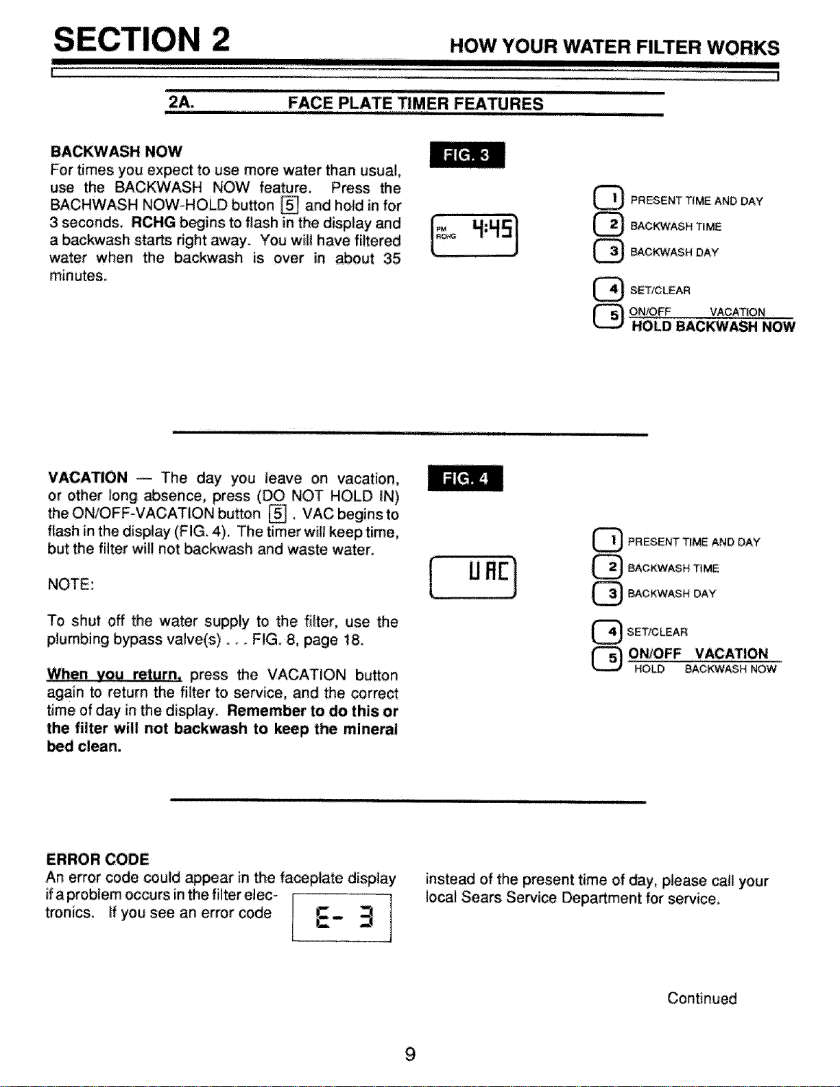
BACKWASH NOW
For times you expect to use more water than usual,
use the BACKWASH NOW feature. Press the
BACHWASH NOW_HOLD button [] and ho_d in for
3 seconds. RCHG begins to flash in the display and
a backwash starts right away'. You wii! have filtered
water when the backwash is over in _out 35
minutes.
F
PRESENT T_ME AND DAY
BACKWASH TIME
BACKWASH DAY
_"_} SET/CLEAR
QN/O,FF VACATION
HOLD BACKWASH NOW
VACATION _ The day you !eave on vacation,
or other long absence, press (DO NOT HOLD IN)
theON/OFF-VACATiON button []. VAC beginsto
flash in the display (FIG. 4). The timer will keep time,
but the filter will not backwash and waste water.
NOTE:
To shut off the water supply to the fi{ter, use the
plumbing bypass valve(s) .... FIG, 8, page 18,
When you return_ press the VACATION button
again to return the filter to service, and the correct
time of day in the display, Remember to do this or
the filter will not backwash to keep the mineral
PRESENT TIME AND DAY
@ CKWASH TIME
BACKWASH DAY
SET/CLEAR
ON/OFF VACATION
HOLD BACKWASH NOW
ERROR CODE
An error code could appear in the fa_plate display
if a problem occurs in the filter elec-
tronics, if you see an error code
instead of the present time of day, please call your
local Sears Service Department for service.
Continued
9
i
III1_1
HOW YOUR WATER FILTER WORKS
I
J
2A-. FACE PLATE TIMER FEATURES
TIMER "POWER-OUTAGE MEMORY" -- If electri_
cal power to the timer goes off, the "memory" buitt into
timer circuitry keeps a!l settings for 5 hours (mini-
mum) or more. The display is blank and the filter will
not backwash. When ele_rical power comes on, 1 of
2 things will happen.
1. The present time of day will show, meaning the
timer memory has kept all settings,
NOTE:
If the filter was in a backwash when power was lost,
it will now finish the cycle.
2. The display will show a time, but it wil! be
flashing. The timer memory did not keep the
time settings and they must be reset, pages 7
and 8.
The flashing display is to remind you to reset
the timer.
NOTE:
When power comes on, the flashing display
returns to a time of 12:00 AM Sunday, then begins
to keep time again, if you do not reset all time
settings, the filter will backw_h 3 days each week,
However, backwash will most likely be on the
wrong days and at the wrong time.
If the filter w_ in a backwash when power went off,
the valve will return to service position without
finishing the cycle. To start another backwa_sh...
.., use BACKWASH NOW, page 9,
10
HOW YOUR WATER FILTER WORKS
H] I
1
FILTER APPLICATIONS
i !11!i! ii!1
Sears water filters are sometimes instal!ed alone in the water system, but most often other water treat-
ing equipment is needed. Always be sure to have your wa_r tested by a qualified testing laboratow.
ff you need help, ask at your Sears store, or call Seam Water Line, 1_00J,26-9345.
CLARIFYING FILTER
ASears Clarifying Filter takes sediments such asdirt,
sand, silt, clay and fine organic matter out of water.
You can see sodiments in water by filling a clear
drinking glass. When held up to light, you can see the
particles floating in the water, or settled to the bottom
of the glass. The filter is filled with "filter aggregate"
mineral that traps and holds the sediments as the
water flows through it.
The Clarifier isso metimes installed alone, but is often
followed by a water softenen Besides softening the
water, the water softener catches sediments that
may get through the filter.
NOTE:
If you will install the clarifying filter along with a Sears
Solution Dispensing System, read the dispensing
system owners manual for treating a private well
before installing.
NEUTRALIZER FILTER
All water, when chemically analyzed, is either acid,
neutral or base (alkaline). To measure this, the water
is given a pH value between 0 and 14. Water is acid
if the pH is from 0 to 6.9. At 7, the water is neutral, and
above that the water is alkaline.
Your Sears neutralizing filter treats acid water when
the pH is from 6.0 to 6.7. A Sears Cartridge Filter with
a Phosphate Crystal Cartridge is often used to treat
water with a pH of 6.8 to 6.9. Acid water shortens the
life of iron pipe, corrodes copper and brass pipe, and
makes green stains on plumbing fixtures. In time, it
will even etch porcelain enamel. The filter has a
special mineral (Neutralite) that raises the pH of the
water to help reduce these acid water problems.
TASTE & ODOR FILTER
A Sears taste & odor filter removes most tastes, odors
and ce_ain organic colors from water. Bad tastes and
odors come from many different causes. Often, one
causes the other. The activated ca_on bed, in the
taste & odor filter, has a great ability, for _king tastes
and odors out of water.
NOTE:
If your water has hydrogen sulfide (rotten egg taste or
odor), be sure to get a qualified testing i_oratories
recommendation for proper treatmenL
11
I
i11
HOW YOUR WATER FILTER WORKS
IIIII II
i
ATER.I.S
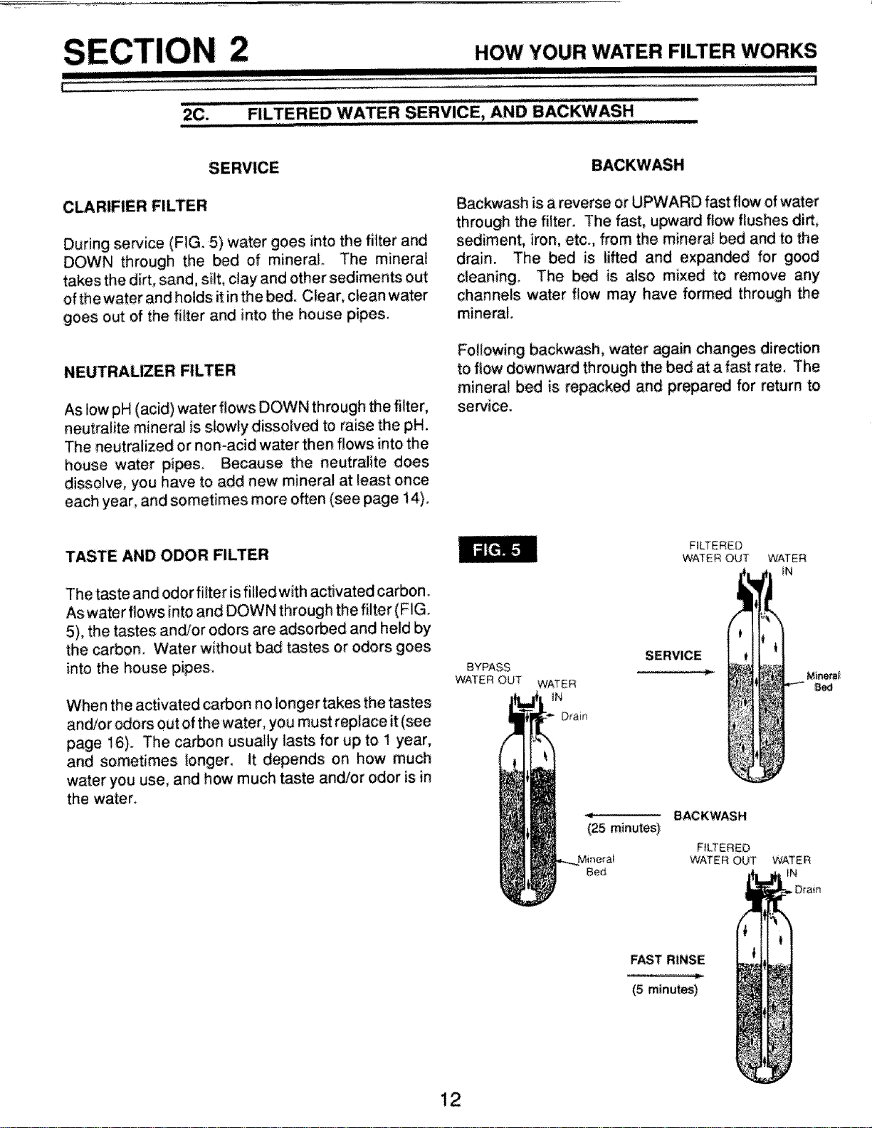
2C. FILTERED W ERVICE, AND BACKWASH,
CLARIFIER FILTER
During sewice (FIG. 5) water goes into the filter and
DOWN through the bed of mineral. The mineral
takes the dirt, sand, silt, clay and other sediments out
of the water and holds itin the bed. Clear, clean water
goes out of the filter and into the house pipes_
NEUTRALIZER FILTER
As low pH (acid) water flows DOWN through the filter,
neutralite mineral is slowly dissolved to raise the pH,
The neutralized or non-acid water then flows into the
house water pipes Because the neutralite does
dissolve, you have to add new mineral at least once
each year, and sometimes more often (see page 14).
Backwash is a reverse or UPWARD fast flow of water
through the filter, The fast, upward flow flushes dirt,
sediment, iron, etc., from the mineral bed and to the
drain. The bed is lifted and expanded for good
cleaning. The bed is also mixed to remove any
channels water f!ow may have formed through the
mineral.
Following backwash, water again changes direction
to flow downward through the bed at a fast rate, The
mineral bed is repacked and prepared for return to
service.
TASTE AND ODOR FILTER
The taste and odor filter isfilledwith activated carbon.
As water flows into and DOWN through the filter (FIG.
5), the tastes and/or odors are adsorbed and held by
the carbon. Water without bad tastes or odors goes
into the house pipe&
When the activated ca_on no longer takes the tastes
and/or odors out of the water, you must replace it (see
page 16). The ca(Don usually lasts for up to 1 year,
and sometimes longer, it depends on how much
water you use, and how much taste and/or odor isin
the water.
BYPASS
WATER OUT
WATER
tN
Drain
(25 minutes)
Mine_a_
Bed
FILTERED
WATER OUT
SERVICE
BACKWASH
FILTERED
WATER OUT
FAST RINSE
(5 minutes)
WATER
IN
Minera_
8ca
WATER
_N
)rain
12
CARE OF YOUR FILTER
irrlr
3-A. KEEP THE FILTER FROM FREEZING
if the filter is installed where it could freeze (summer
_bin, lake home, etc_), you must drain all water
from it to stop possible freeze damage. To drain the
filter
lJ
2_
w
5.
Close the shut-off valve on the house main water
pipe, near the water meter or pressure tank.
Open a faucet in the filtered water pipes to vent
pressure in the filten
Looking at FIG. 8 on page 18, move the stem in
a single bypass valve to bypass. Close the inlet
and outlet valve in a 3-valve bypass system, and
open the bypass valve.
Unplug the transformer at the wall outlet.
Pull the holding clip to remove the drain fitting,
with drain hose attached, from the valve_ DO
NOT LOSE THE BLACK RUBBER FLOW PLUG
AND RETAINER_
6. Remove the plastic clips (see key #41, page 26)
and pull the adaptors or bypass valve from the
inlet and outlet,
7_
Move the filter close to the fioor drain, SLOWLY
and CAREFULLY (the filter is heavy) tip the filter
over so the valve inlet and outlet are over the
drain, Allow water to drain from tank. DO NOT
REST THE FILTER ON THE INLET AND OUT-
LET FITTINGS OR THEY WiLL BREAK.
8_
Tip the bottom of the filter up a few inches and
hold until all water has drained. Leave the filter
laying like this until you are ready to use it. Plug
the inlet and outlet with rags to keep di_, bugs,
etc. out.
13
CARE OF YOUR FILTER
I I II1[IHIIIII[_
i =
i iiiiir[i
3B.
ADDING MINERAL... NEUTRALIZER FILTER
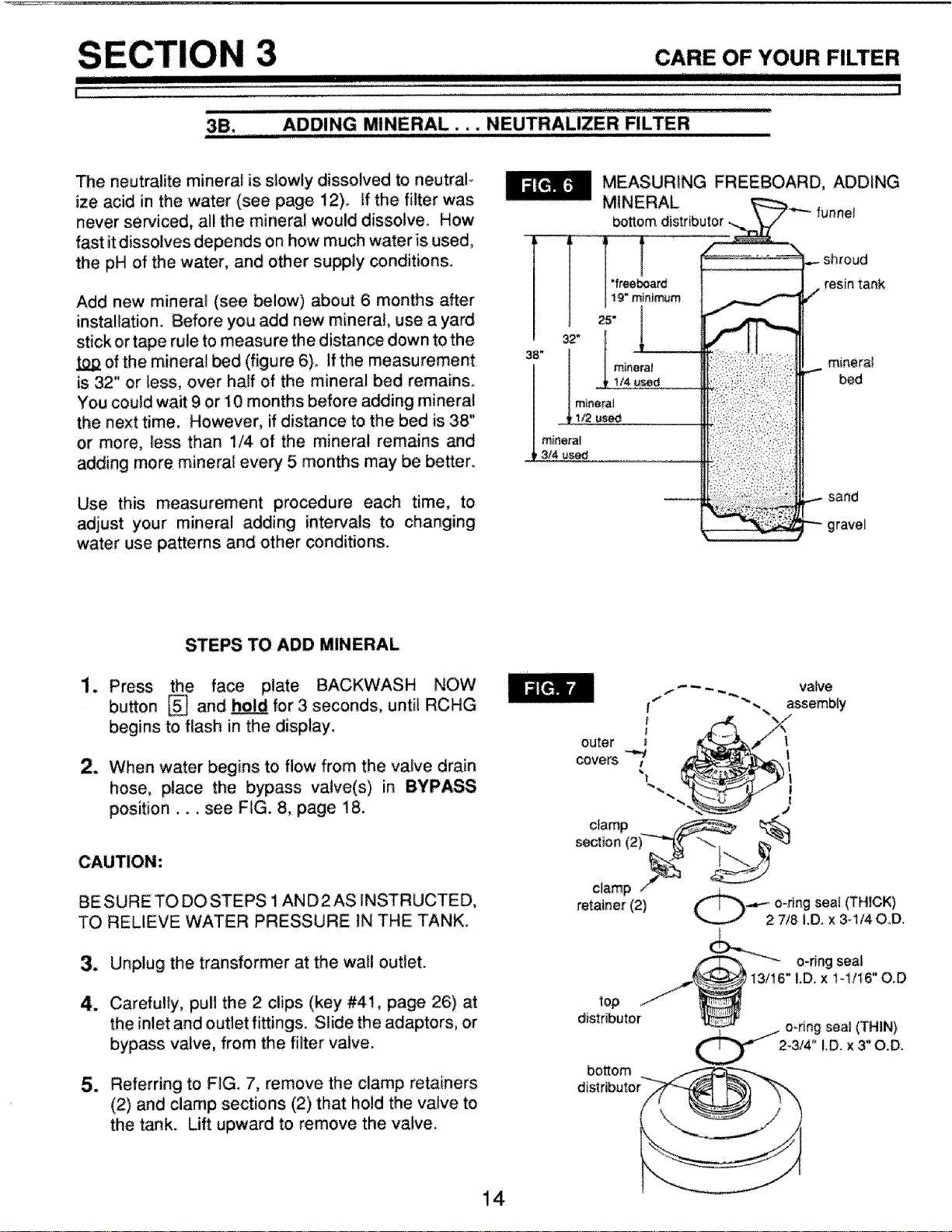
The neutralite minera_ is slowly dissolved to neutral-
ize acid in the water (see page 12)_ ff the filter was
never serviced, all the mineral would dissolve_ How
fast itdissolves depends on how much water is used,
the pH of the water, and other supply conditions.
Add new mineral (see below) about 6 months after
installation. Before you add new mineral, use a yard
stick or tape rule to measure the distance down to the
of the mineral bed (figure 6). if the measurement
is 32" or less, over haft of the mineral bed remains.
You could wait 9 or 10 months before adding mineral
the next time. However, if distance to the bed is 38"
or more, _ess than 1/4 of the mineral remains and
adding more minera_ every 5 months may be better.
Use this measurement procedure each time, to
adjust your mineral adding intervals to changing
water use patterns and other conditions.
m
38"
11
rninera_
3/4 used
MEASURING FREEBOARD, ADDING
MINERAL _._
_ttom distributor_ funnel
i"- shroud
resin tank
/
minerat
bed
.._ sand
gravel
STEPS TO ADD MINERAL
1. Press the face plate BACKWASH NOW
bu_on [] and hold for 3 seconds, until RCHG
begins to flash in the display.
2. When water begins to flow from the valve drain
hose, Diace the bypass valve(s) in BYPASS
position.., see FIG. 8, page 18.
BE SURE TO DO STEPS 1 AN D 2 AS INSTRUCTED,
TO RELIEVE WATER: PRESSURE IN THE TANK,
3. Unplug the transformer at the wail out{et.
4. Carefully, pull the 2 clips (key #41, page 26) at
the inlet and outlet fittings. Stide the adaptors, or
bypass valve, from the filter valve.
5. Referring to FiG. 7, remove the clamp retainers
(2) and clamp sections (2) that hold the valve to
the tank. Lift upward to remove the valve,
valve
outer
COVetS
top
distributor
bosom
C_ o_ringseal(THIN)
2-3/4 LD, x 3" O.D.
14
CARE OF YOUR FILTER
'1
DOING .................
A MINERAL,.. NEUTRALIZER FILTER
II
6. Remove the o-rings (3) and top distributor from
the top of the tank,
7. To make room for the new mineral, use a hose to
siphon water from the tank,
8. Using a large neck funnel, add new mineral into
the tank.
DO NOT ADD MINERAL INTO THE BOTTOM
DISTRIBUTOR. Temporarily plug the distributor
tube to prevent accidental mineral spills into it,
DO NOT OVERFILL the tank. Freeboard area (s_
FiG. 6) is needed for proper backwashing, If you
have mineral remaining, you can use it the next
time you refill the tank.
9, Use water to flush the tank top opening Then,
replace the top distributor and 3 o-rings. Be sure
to locate o-ring seals correctly.., FIG. 7.
10. Carefully, install the valve assembly and retain-
ing clamps. DOUBLE-CHECK TO BE SURE
CLAMPS AND RETAINERS ARE SECURELY
FASTENED iN PLACE.
11. Referring to your installation manuat, reconnect
thefiltertothe plumbing, BESURETHE PLUMB-
iNG IS HELD FIRMLY IN PLACE, IN THE VALVE
iNLET AND OUTLET,
12. Place the valve drain hose at the drain point and
secure in place,
13. Return the plumbing bypass valve(s) to SERV-
ICE position.
14. Plug the transformer into the wall outlet. The
filter will complete the backwash cycle, started in
step 1, and will automatically return to service,
15
E
III!1!l
CARE OF YOUR FILTER
i
30. REPLACING MINERAL.., TASTE & ODOR FILTER
!
Average life of the activated carbon mineral bed is
about 1 year (see page 12), It,s time to replace the
bed when the tastes and!or odors begin to return in
the water supply. Do the following,
STEPS TO REPLACE MINERAL
1. Press the face plate BACKWASH NOW
button [] and _ for 3 seconds, until RCHG
begins to flash in the display.
2. When water begins to flew from the valve drain
hose, place the bypass valve(s) in BYPASS
position __, see FIG. 8, page t8.
BE SURE TO DO STEPS i AND 2 AS iNSTRUCTED,
TO RELIEVE WATER PRESSURE IN THE TANK.
3_
4.
5_
6_
7_
Unplug the transformer at the wall outlet,
Carefully, pull the 2 clips (key #41, page 26) at
the inlet and outlet fittings. Slide the adaptors, or
bypass valve, from the filter valve,
Referring to FIG. 7, page 14, remove the clamp
retainers (2) and clamp sections (2) that hold the
valve to the tank. Lift upward to remove the
valve.
Remove the o-rings (3) and top distributor from
the top of the tank.
Next to a floor drain, carefully tip the tank over,
catching the used carbon in a burlap sack or
other suitable container. Remove the bottom
distributor assembly, and flush the inside of the
tank with water.
HANDLE THE TANK CAREFULLY. FULLOF WATER
AND CARBON, IT IS VERY HEAVY. DO NOT
ATTEMPT TO LIFT IT BY YOURSELF. DO NOT
DROP AND BREAK THE TANK.
m
Stand the tank upright and replace the bottom
distributor assembly. Tem_rarily, plug the top
end of the distributor (use rag, etc.) to prevent
accidental mineral spills into it,
9_ Using a large neck funnel (FIG, 6), first add 17
Ibs. of gravel, fottowed by 10 Ibs. of filter sand.
Next, add the _ of activated carbon. Use
water sparingly to assist carbon flow through the
funnel.
NOTE:
Be sure the bottom distributor is centered in the tank
while adding mineral.
10.
11.
12.
13.
14.
15,
Use water to flush the tank top opening Then,
replace the top distributor and 3 o_rings. Be sure
to locate raring seals correctly... FIG. 7, page
14.
Carefully, install the valve assembly and retain-
ing clamps, DOUBLE-CHECK TO BE SURE
C_MPS AND RETAINERS ARE SECURELY
FASTENED IN PLACE.
Referring to your installation manual, reconnect
the filter to the plumbing. BE SURE THE PLUMB-
ING IS HELD FIRMLY INPLACE, INTHE VALVE
iNLET AND OUTLET.
Place the valve drain hose atthe drain point and
secure in place.
Return the plumbing bypass valve(s) to SERV-
ICE position.
Plug the transformer into the wall outlet. The
filter will complete the backwash cycle, started in
step 1, and will automatically return to service.
NOTE:
All new carbon mineral contains some smalter than
normal panicles called "fines." Backwashing the filter
removes the fines. If, after the backwash in step 15
is over, fines are still in the filtered water, repeat step
1 for added backwashing.
16
CARE OF YOUR FILTER
,,nnnnnmini IIIIIIII1[1[I
! I
F
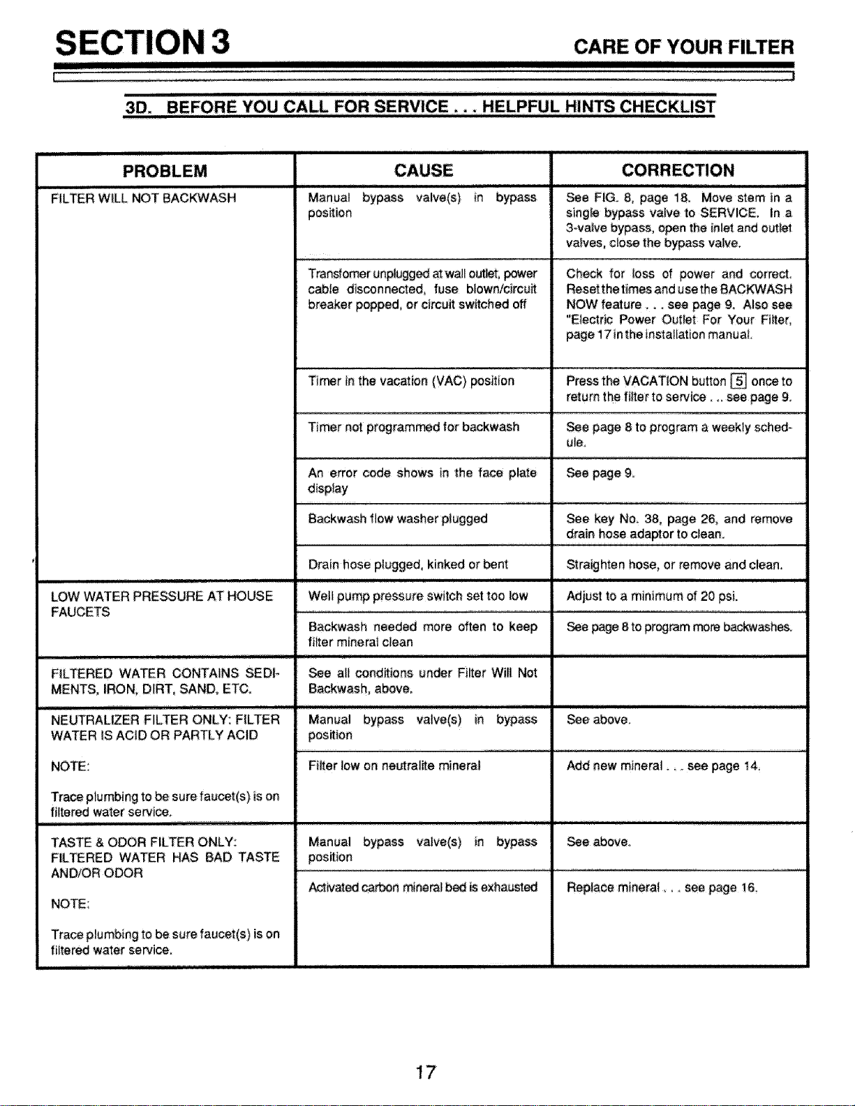
3D. BE ORE YOU CALL FOR SERVICE _,. HELPFUL HINTS CHECKLIST
, ,ll_ ,ll, ,_IIIIII II!1I!1! I
ii
FILTER WILL NOT BACKWASH
LOW WATER PRESSURE AT HOUSE
FAUCETS
iiirll ,ll]nrl]nn_l
FILTERED WATER CONTAINS SEDI-
MENTS, IRON, DIRT, SAND, ETC.
_!_r/lllll_fir/ !
NEUTRALIZER FILTER ONLY: FILTER
WATER IS ACID OR PARTLY ACID
NOTE:
Trace plumbing to be sure faucet(s) is on
filtered water service.
irr rrrrrlrlrlllrlllrlrrr I
TASTE & ODOR FILTER ONLY:
FILTERED WATER HAS BAD TASTE
AND/OR O_R
NOTE:
Traceplumbing to besure faucet(s) is on
filtered water service,
i l!!!
Manua! bypass valve(s) in bypass
position
Transfomer unplugged at wall out,t, power
cable disconnected, fuse blown/circuit
breaker popped, or circuit switched off
iii, ii ii iii
See F!G_ 8, page 18. Move stem in a
single bypass valve to SERVICE. In a
3-va_Je bypass, open the inlet and outlet
valves, close the bypass valve.
Check for loss of power and _rrect
Reset the times and use the BACKWASH
NOW feature .... see page 9. Also see
"Electr_ Power Outlet For Your Filter,
page 17 inthe installation manual.
Timer in the vacation (VAC) position Press the VACATION button [] once to
return the filter to service _., see page 9,
Timer not programmed for backwash _e page 8 to program a weekly sched-
ule.
An error code shows in the face plate See page 9.
display
Backwash flow washer plugged _e key No. 38, page 26, and remove
drain hose adaptor to clean.
Drain hose plugged, kinked or bent Straighten hose, or remove and clean.
Well pump pressure switch set toe low Adjust to a minimum of 20 psi.
Backwash needed more often to keep _ p_ 8 to pr_rem more backw_hes.
filter minera_ clean
See all conditions under Filter Will Not
Backwash, above.
Manuai bypass valve(s) in bypass See above
position
Filter low on neutrallte mineral Add new mineral see page 14,
Manual bypass vatve(s) in bypass
position
_ivated c&_cen_neral _ is exhausted
Replace mineral,, see page 16,
17
III1
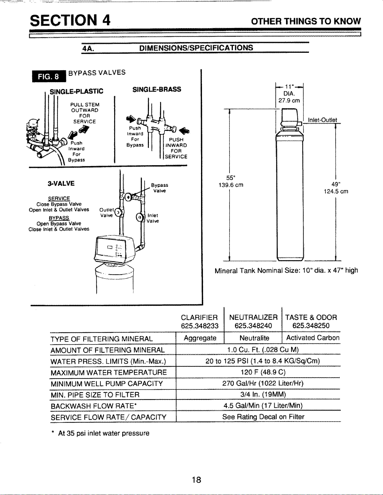
4A.
i
I I I IIIIIII
OTHER THINGS TO KNOW
I!!!11111IIIIII
BYPASS VALVES
PULL STEM
OUTWARD
FOR
SERVICE
For
Bypass
Ctose BypaSS Valve
Open Inlet & Ouitet VaP¢es
_n Bypass Valve
Close Inlet & Out/et Valves
t°..,d r 4!_
For J PUSH
Bypass I INWARD
FOR
SERVICE
iiiiiiii Ijl
Bypass
Valve
TYPE OF FILTERING MINERAL
AMOUNT OF FILTERING MINERAL
WATER PRESS. LIMITS (Min.=Max.)
MAXIMUM WATER TEMPERATURE
MINIMUM WELL PUMP CAPACITY
MIN. P_PE SIZE TO FILTER
BACKWASH FLOW RATE*
SERVICE FLOW RATE/CAPACITY
CLARIFIER
625.348233
Aggregate
55"
139.6 cm
! 1"-,--
DIA.
9 cm
Inlet-Out_et
49"
124_! cm
Mineral Tank Nominal Size: 10" did. x 47" high
I
NEUTRALIZER I TASTE & ODOR
625,348240 ! 62&348250
Neutiaiite I Activated carbon
1.0 cu. FL (_028 Cu M)
20 to 125 PSI (1.4 to 84 KG/Sq/Cm)
120 F (48,9 C)
270 Gai/Hr (1022 LitedHr)
3/4 in, (19MM)
4.5 Gal/Min (17 Liter/Min)
See Rating Decal on Filter
* At 35 psi inlet water pressure
18
II III I I
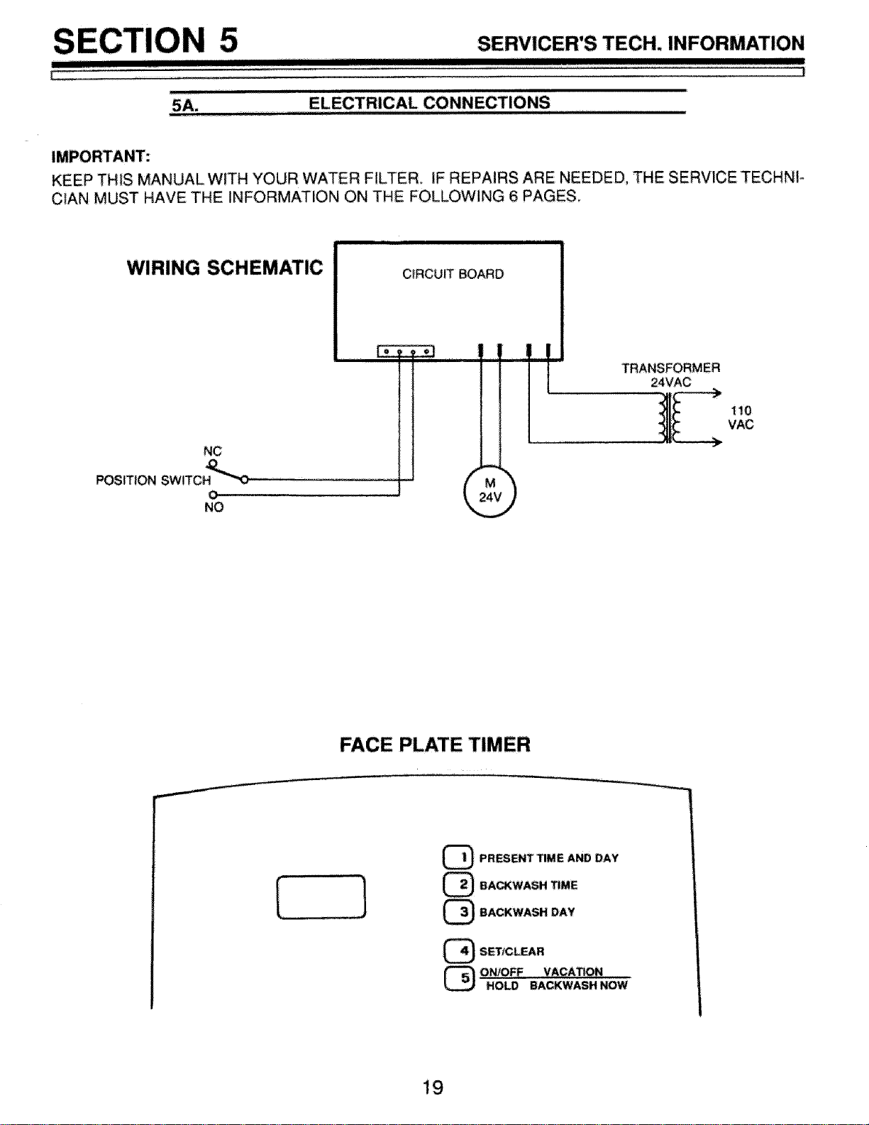
SERVICER'S TECH. INFORMATION
I I IlJlUIIIIIIIIIIIIII III I I
,l=,m
ELECTRICAL CONNECTIONS
KEEP THiS MANUAL WITH YOUR WATER FILTER, IF REPAIRS ARE NEEDED, THE SERVICE TECHNIo
ClAN MUST HAVE THE INFORMATION ON THE FOLLOWING 6 PAGES,
WIRING SCHEMATIC
E
NC
POSITION SWlTC H4_''"_'0
o
NO
CIRCUIT BOARD
24\
110
VAC
FACE PLATE TIMER
[
PRESENT TIME AND DAY
BACKWASH TIME
BACKWASH DAY
1!9¸
E
5 SERVICER'S TECH. INFORMATION
!1 ""
!
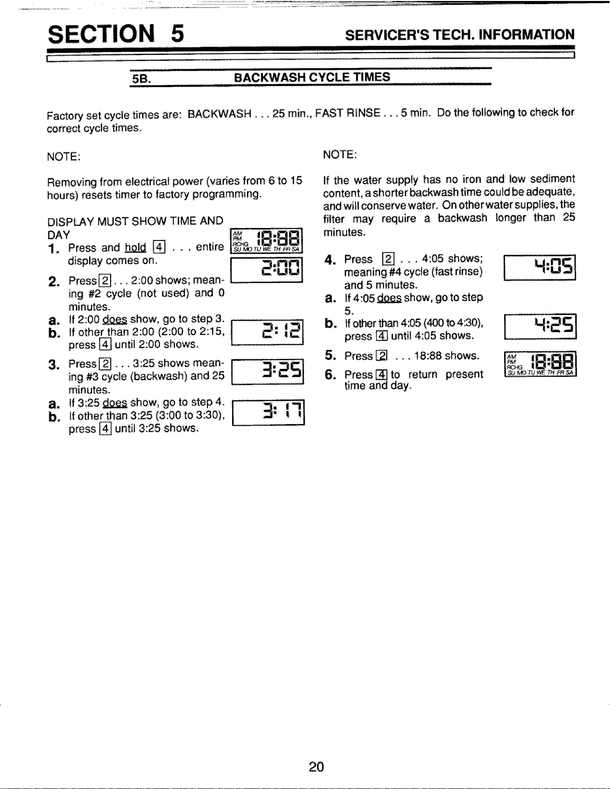
,,,' I"BACKWASHCYCLE TIMES
Factory set cycle times are: BACKWASH.._ 25 min., FAST RINSE... 5 min. Do the following to check for
correct cycle times,
NOTE: NOTE:
Removing from electrical power (varies from 6 to 15
hours) resets timer to factory programming.
DISP_Y MUST SHOW TIME AND
DAY1.Press and_ [].,_entire _orLS_l
2 d'splaYPress[]C°mes°n'2:00shows; meam l_ 2:001
ing #2 cycle (not used) and 0
minutes.
ba. pressff2:00 !sho'W,lfother than[]until2:00 (2:002:00go tOshowstoStep3.2:15, j
minutes.
ba. Pressffotherlf3:25_show,than 3:25{3:OOuntiI 3:25 shows,g° t°t°step 4"3:30)'[_
2: 21
3:251
3: 71
ff the water supply has no iron and bow sediment
content, a shorter backwash time could be adequate,
and will conserve water_ On otherwater supplies, the
_ter may require a backwash longer than 25
minutes.
4. Press [] _ _. 4:05 shows;
meaning #4 cycle (fast rinse)
and 5 minutes.
a. ff4:05_show, go to step
5.
b. ff other than 4:05 (400 to 4:30),
press [] until 4:05 shows,
5. Press_ .. _ 18:88 shows.
6. Press_to return present
time and day.
L
2O
5
_JIL IIIIII!111
I
SERVICER'S TECH. INFORMATION
irl
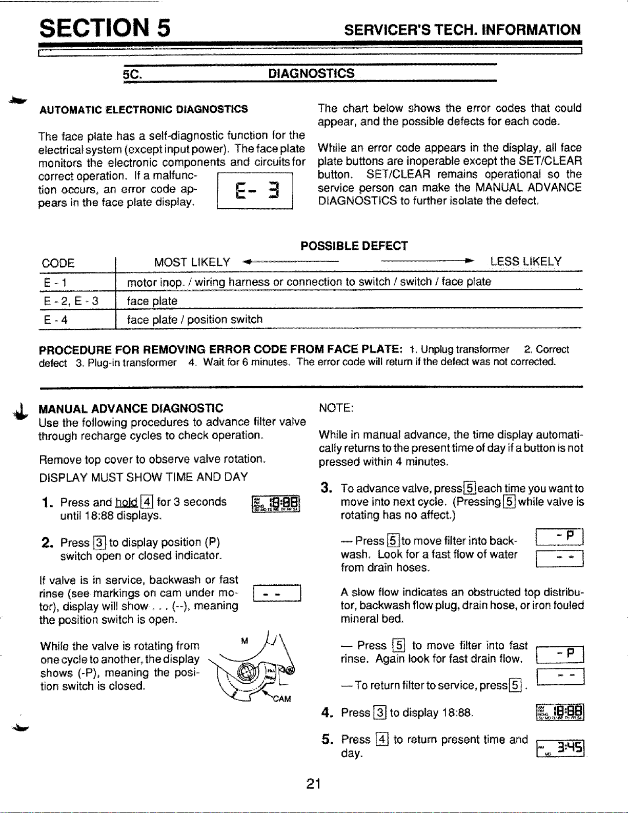
AUTOMATIC ELECTRONIC DIAGNOSTICS
The face plate has a self-diagnostic function for the
electrical system (except input power). The face plate
monitors the electronic components and circuits for
corre_ operation. If a malfunc- i
tion occurs, an error code aP_ l 3
pears in the face plate display.
The chart below shows the error codes that could
appear, and the possible defects for each code.
While an error code appears in the display, all face
plate buttons are inoperable except the SET/CLEAR
button. SET/CLEAR remains operational so the
service person can make the MANUAL ADVANCE
DIAGNOSTICS to further isolate the defect.
¢
4=,,
CODE
E-1
E-2, E-3
E-4
POSSIBLE DEFECT
MOST LIKELY _ _ LESS LIKELY
motor inop. / wiring harness or connection to switch / switch / face plate
face plate
face plate / position switch
PROCEDURE FOR REMOVING ERROR CODE FROM FACE PLATE: 1, Unplug transformer 2, Correct
defect 3, Plug-in transformer 4. Wait for 6 minutes, The error code will return ifthe defect was not corr_ed.
MANUAL ADVANCE DIAGNOSTIC
Use the following procedures to advance filter valve
through recharge cycles to check operation,
Remove top cover to observe valve rotation.
DISPLAY MUST SHOW TIME AND DAY
1. Press and _[] for 3 seconds
until 18:88 displays.
2. Press [] to display position (P)
switch open or closed indicator.
If valve is in service, backwash or fast
rinse (see markings on cam under mo-
tor), display will show. _. (--), meaning
the position switch is open.
NOTE:
While in manual advance, the time display automati-
cally returns to the present time of day if a button is not
pressed within 4 minute&
3_
To advance valve, press_each time you want to
move into next cycle, (Pressing [] while valve is
rotating has no affect.)
-- Press _to move filter into back- / " P !
wash. Look for a fast flow of water [ _ . ]
from drain hose&
A slow flow indicates an obstructed top distribu_
tor, backwash flow plug, drain hose, or iron fouled
mineral bed_
While the valve is rotating from
one cycle to another, the display
shows (-P), meaning the posi-
tion switch is closed.
Press _ to move filter into fast
rinse. Again look for fast drain flow.
_Toreturnfiltertoservice, press_. I -" I
4. Press _ to display 18:8&
5. Press [] to return present time and i_ 3,H51
day. ,
21
5 SERVICER'S TECH. INFORMATION
immzliilllJI [1[ I J HIIII IIIII II IIIlU IIIII
i ........................... _ii1
i fl u_uiii iiiii I[HT
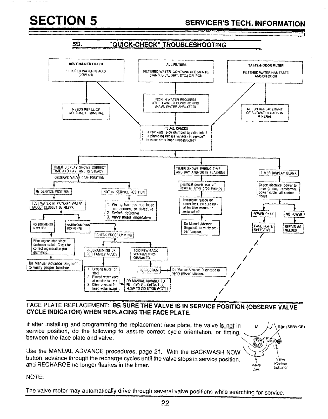
5D, "QUICK-CHECK" TROUBLESHOOTING .............
[TIMER DISPLAY SHOWS CORRECT'I
T_MEANDOAY._NOJSSTEADYJ
OBSERVEVALVE CAM POSmOFI
[(.sERwc__osi_D.]
TEIIEO WATER I
I FAOC_TCLOSESTTO RLTER I
POSUTtON]
!
Wi_ing harness has.ioose
conneci!ons.Or deteciive
I Filler reg_e_aledsin_ -
s_s|omercaI_e_,Ch_or _ _
_fflg, / / WAS£ES PRO- /
.t. " --' l_,A,,,_D. !
[oo oooa, ,voooo ]
to verifyproper l_nclion, _Do ManualAclvee_Diagnosticto
q
_erify proper funeral: ,_
I _USUal fil-ri,.-IFILLCYCL_- HCECR FILL I /
FACE PLATE REPLACEMENT: BE SURE THE VAL'VE ISIN SERVICE POSITION (OBSERVE vALV!E'''
CYCLE INDICATOR)WHEN REPLACING THE FACE PLATE.
If after installing and programming the replacement face plate, the valve _ in
service position, do the following to assure correct cycle orientation, or timing,
between the face plate and valve.
Use the MANUAL ADVANCE procedures, page 21. With the BACKWASH NOW
button, advance through the recharge cycles until the valve stops inservice position, _ v_
and RECHARGE no longer flashes in the timer, v_v_ Po_o_
Cam _r_ ¢ator
NOTE:
The valve motor may automatically drive through several valve positions while searching for service.
nl_lnr !,1 ,, _,Jl u r I1,1,
IIflllllfl]nm_ I I!1
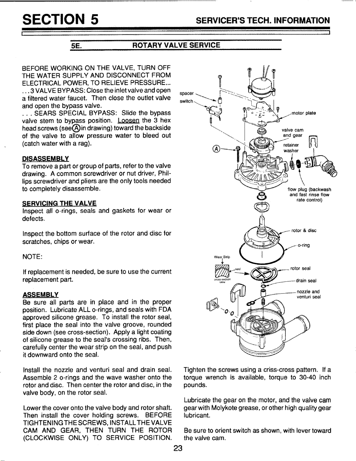
ROTARY VALVE SERVICE
I
BEFORE WORKING ON THE VALVE, TURN OFF
THE WATER SUPPLY AND DISCONNECT FROM
ELECTRICAL POWER, TO RELIEVE PRESSURE..
._. 3 VALVE BYPASS: Close the inlet valve and open
a filtered water faucet. Then close the outlet valve
and open the bypass valve.
... SEARS SPECIAL BYPASS: Slide the bypass
valve stem to bypass position. _ the 3 hex
head screws (see_in drawing) toward the backside
of the valve to allow pressure water to bleed out
(cinch water with a rag).
To remove a part or group of parts, refer to the valve
drawing. A common screwdriver or nut driver, Phil-
tips screwdriver and pliers are the only tools needed
to completely disassemble.
SERVICINGTHE VALVE
Inspect all o_rings, seals and: gaskets for wear or
defects.
inspect the bottom surface of the rotor and disc for
scratches, chips or wear.
NOTE:
if replacement is needed, be sure to use the current
replacement part.
Be sure all parts are in place and in the proper
position. Lubricate ALL o-rings, and seals with FDA
_proved silicone grease. To install the rotor seal,
first place the seal into the valve groove, rounded
side down (see cross-section). Apply a light coating
of silicone grease to the seal's crossing ribs. Then,
carefully center the wear strip on the seat, and push
it downward onto the seal.
Install the nozzle and venturi seal and drain seal.
Assemble 2 o-rings and the wave washer onto the
rotor and disc. Then center the rotor and disc, in the
valve body, on the rotor seal.
Lower the cover onto the valve body and rotor shaft.
Then install the cover holding screws.
TIGHTENING THE SCREWS, INSTALLTHE VALVE
CAM AND GEAR, THEN TURN THE ROTOR
(CLOCKWISE ONLY) TO SERVICE POSITION.
23
spacer_._
re.her
washer
plate
\
flow plug (backwash
and fast rinse flow
rate control)
& disc
Tighten the screws using a criss-cro_ pattern_ if a
torque wrench is av_lable, torque to 30-40 inch
pounds.
Lubricate the gear on the motor, and the valve cam
gear with Molykote grease, or other high quality gear
lubricanL
Be sure to orient switch as shown, with lever toward
the valve cam.
I
5 SERVICER'S TECH. INFORMATION
II
i
......................ilriiiii'r..... ' '-
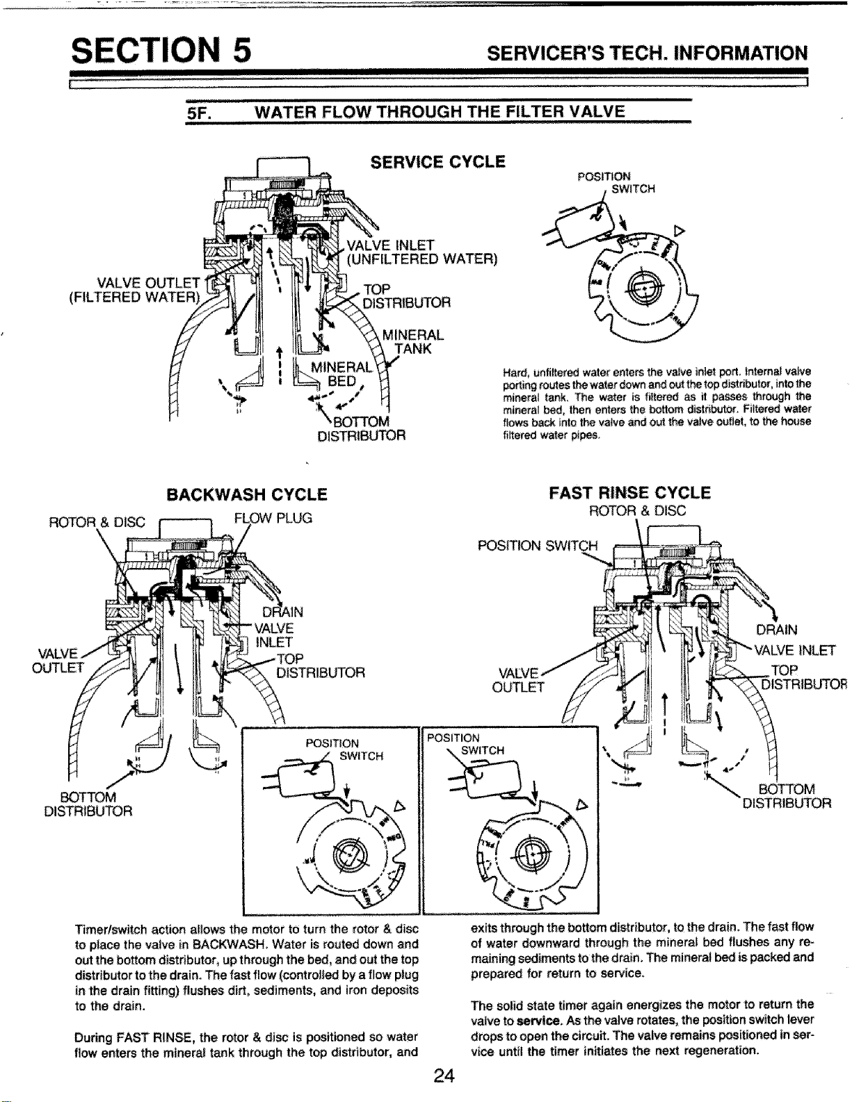
WATERFLOW THROUGH THE, FILTER VA VE
SERVICE CYCLE
POSITION
VALVE OUTLET
(FILTERED
INLET
(UNFILTERED WATER)
TOP
DISTRIBUTOR
MINERAL
TANK
MINERAL
BED,
DIS_IBUTOR
Hard, unfiltered water enters the valve inlet port. !Internal v_ve
_ing routes the water down and out _ top distdbuler, into the
mi_rat tank. The water is filtered as it passes _ro4Jgh the
mineral bed, then enters the bottom distdbuto_, Fiitere_ water
flows back into the valve and Out the valve outlet, to the house
filtered water p_pes.
ROTOR &
BACKWASH CYCLE
PLUG
FAST RINSE CYCLE
ROTOR & DISC
PosmoN SWITCH
OUTL_
INLET
DISTRIBUTOR
OUTLET
DRAIN
INLET
TOP
DISTRIBUTO£
BOTTOM
DISTRIBUTOR
POSITION
SWITCH
POSITION
SWITCH
Timer/switch action allows the motor to turn the rotor & disc
to place the valve in BACKWASH. Water is routed down and
out the bott_ distributoq up through the bed, and out the top
distributor to the drain. The fast flow (controlled by a flow plug
in the drain fitting) flushes dirt, sediments, and iron deposits
to the drain.
During FAST RINSE, the rotor & disc is positioned so water
flow enters the mineral tank through the top distributor, and
24
The solid state timer again energizes the motor to return the
valve toservice, As the valve rotates, the position switch lever
drops to open the circuff. The valve remains positioned in ser-
vice until the timer initiates the next regeneration.
exits through the bottom distributor, to the draim The fast flow
of water downward through the mineral bed flushes any re-
maining sediments to the drain. The mineral _ ispacked and
prepared for return te seP,_ice.
REPAIR PARTS
IIII1!IIIIIll!lilt III!11 I
| !
14
VALVE COVER
(2)_ see
page 26
16
17
18
20 I
J
--2_ I
1
"22//
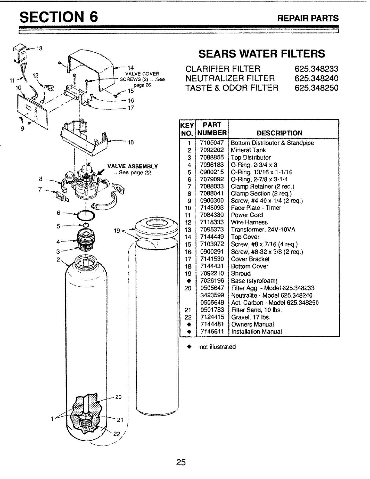
SEARS WATER FILTERS
CLARIFIER FILTER
NEUTRALIZER FILTER
TASTE & ODOR FILTER
KEY PART
........i........7i 05047 Bottom"*si_iibu'tor & Stand'pipe
2 709_02
3 7088855
4 7096183
5 0900215
6 7079092
7 7088033
8 7088041
9 0900300
10 71460_
11 7084330
12 711_33
13 7095373
14 7144449
15 7103972
16 0900291
17 7141530
18 71_1
19 7092210
7026196
20 0505647
3423599
050564.9
0501783
7124415
71_1
7146611
Mineral Tank
Top Distributor
O-Ring, 2-3/4 x 3
O-Ring, 13/16 x lq/16
O_Ring, 2-7/8 x 3-1/4
Clamp Retainer (2 req.)
Clamp Se_ion (2 req.)
Screw, #4_40 x 1/4 (2 req,)
Face Plate - Timer
Power Cord
Wire Harness
Transformer, 24V-10VA
Top Cover
Screw, _ x 7/16 (4 req.)
Screw, _-32 x 3/8 (2 req.)
Cover Bracket
Bottom Cover
Shroud
Base (styrofoam)
Fiker Agg, - Model 625.348_3
Neutralite _Model 625348240
Act Cain - Model 625348250
21 Filter Sand, 10 Ibs.
22 Gravel, 17 Ibs.
,I_ Owners Manual
Installation Manual
not illustrated
[TI
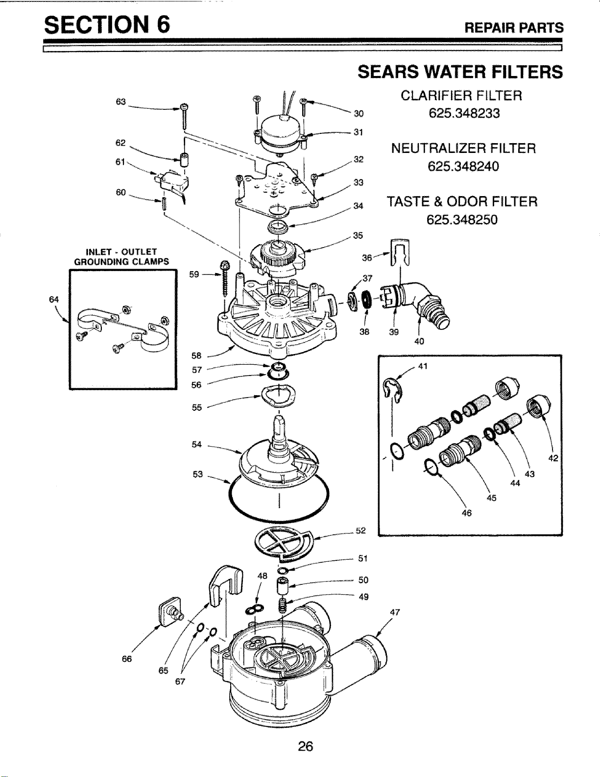
REPAIR PARTS
I
SEARS WATER FILTERS
30
31
CLARIFIER FILTER
NEUTRALIZER FILTER
,_ TASTE & ODOR FILTER
64
\
INLET - OUTLET _-_.
GROUNDING CLAMPS
-- 59
38 39
43
44
49
47
66
65
67
I
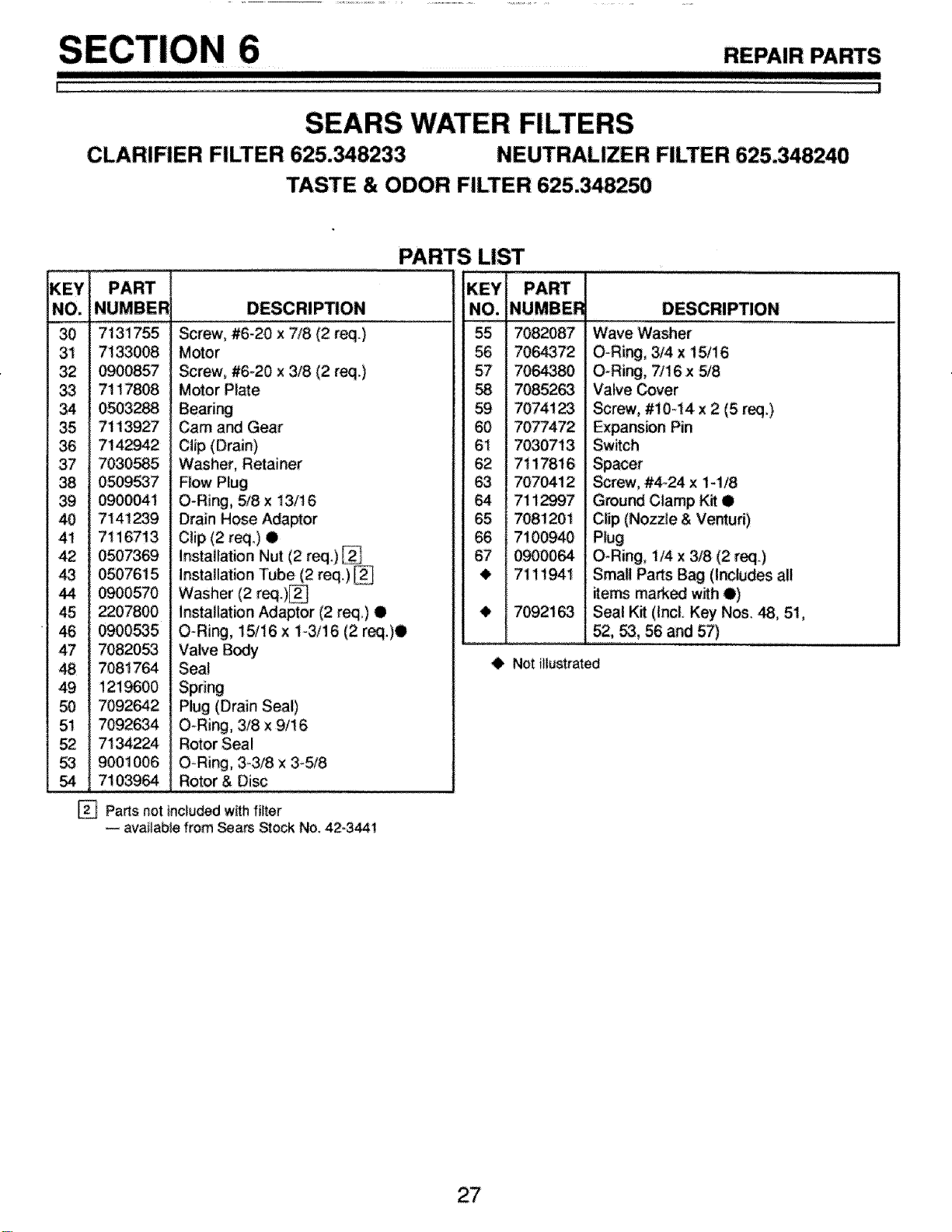
REPAIR PARTS
SEARS WATER FILTERS
CLARIFIER FILTER 625.348233 NEUTRALIZER FILTER 625.348240
TASTE & ODOR FILTER 625.348250
PARTS LIST
KEY
NO,
30 7131755 Screw, #6,20 x 7/8 (2 req.) 55
31 7133008 Motor
32 0900857 Screw, #6-20 x 3/8 (2 r_.) 57
33 71 t7808 Motor Plate 5,8
34 0503_ Bearing 59
35 7113927 Cam and Gear 60
36 7142942 Clip (Drain) 61
37 7030585 Washer, Retainer 62
0509537 Flow P!ug 63
39 0900041 O-Ring, 78 x 13/16 64
40 7141239 Drain Hose Adaptor 65
41 7116713 Clip(2 req.) • 66
42 0507369 installation Nut (2 req) _ 67
43 0507615 installation Tube (2 req.) _
44 0900570 Washer (2 req.)_
45 _07800 installation Adaptor (2 req,) • t
46 0900535 O-Ring, 15/16 x t-3/16 (2 req,)O
47 70820_ Valve Body
48 7081764 Seal
49 t21_00 Spring
50 7092:642 Plug (Drain Seal)
51 7092634 O-Ring, 318 x 9/16
52 7134224 Rotor Seal
53 9001006 O-Ring, 3-3/8 x 3_5/8
54 7103964 Rotor & Disc
Parts not includedwithfilter
available from Sears St_k No. 42-3441
7082087
7064372
7064380
7085263
7074123
7077472
7030713
7117816
7070412
7! 12997
7081201
7100940
09OO064
7111941
7092163
Wave Washer
O-Ring, 3/4 x 15/16
O-Ring, 7/16 x 5/8
Valve Cover
Screw, #10-14 x 2 (5 req.)
Expans_n Pin
Swffch
Spacer
Screw, #4_24 x 1-1/8
Ground Clamp Kit •
Clip (Nozzle & Venturi)
Plug
O-Ring, 1/4 x 3/8 (2 req.)
Small Parts Bag (Includes all
items mark_ with O)
Seal Kit (Incl, Key Nos. 48, 51,
52, 53, 56 and 57)
• Not illustrated
27
Your Sears Water Filter has added value when you consider that
Sears has service uni_ nationwide staffed with Sears trained tech-
nicians - professional technicians specifically trained on Sears
products, having the parts, tools and equipment to ensure that we
meet our pledge to you _ "We Service What We Sell."
MODEL NOS.
The model number of your water filter is found on the rating decal.
This decal is on the backside of the filter top cover,
HOW TO ORDER
REPAIR PARTS
SHOULD A NEED EVER
EXIST FOR REPAIR
SERVICE OR PARTS:
FOR REPAIR SERVICE, CALL
THIS TOLL FREE NUMBER:
WHEN ORDERING REPAIR PARTS, ALWAYS GIVE THE FOL-
LOWING iNFORMATION:
PART NUMBER
MODEL NUMBER
PART DESCRIPTION
NAME OF ITEM
When Sears arranges the installation, you can be sure the job is
done right, We wilt arrange for professional workmanship, .. and
we'll take care of the entire project, What's more, during installa_
tion you get insured protection. _. against property damage and
also against accidents to workmen, All you have to do is to talk to
your Sears salesperson or call your nearest Sears store today for
detailed information,
FOR REPLACEMENT PARTS
INFORMATION AND
ORDERING, CALL THIS TOLL
FREE NUMBER:
.r,,rl irll i
Sears, Roebuck and Co., Chicago, Ill. 60684 U.S.A.
#7144481 (6/94)