OWNER'S
MANUAL
MODEL NOS.
625.348235
Clarifier
625.348242
Neutralizer
625.348252
Taste & Odor
Caution:
Read and Follow
All Safety Rules and
Operating Instructions
Before First Use of
This Product.
If you have questions when
installing, operating or main-
taining your filter, and when
setting the timer, call this
toll-free number...
1-800-426-9345
(M-F, 7am-8pm, CST)
For repair or replacement
parts, call this toll-free num-
ber...
1-800-366-7278
See back cover for other
Sears service numbers.
www.KenmoreWater.com
SAVE THIS MANUAL
Water Filters
• Warranty
• Start Up / Setting Timer
• How It Works
• Care Of
• Specifications
• Repair Parts
®
Printed on recycled paper
Sears, Roebuck and Co., 3333 Beverly Road, Hoffman Estates, IL 60179 USA
PRINTED IN U,S,A. 7282661 (Rev. C 10/15/09)
W
A
R
R
A
N
T
Y
SEARS RESIDENTIAL WATER FILTER
FULL ONE YEAR WARRANTY ON FILTER
For one year from the date of purchase, when this filter is installed and maintained
in accordance with our instructions, Sears will repair, free of charge, defects in
material or workmanship in this water softener.
FULL FIVE YEAR WARRANTY AGAINST LEAKS
For five years from the date of purchase, Sears will furnish and install a new current
model water filter tank, free of charge, if the tank develops a leak.
TO OBTAIN WARRANTY SERVICE, SIMPLY CONTACT THE NEAREST SEARS
SERVICE CENTER THROUGHOUT THE UNITED STATES. This warranty
applies only while this product is in use in the United States.
This warranty gives you specific legal rights, and you may have other rights which
vary from state to state.
Sears, Roebuck and Co., D/817 WA, Hoffman Estates, IL 60179
If you want your water filter professionally installed, talk to your Sears Salesman. He will arrange for a
prompt, quality installation by Sears Authorized installers.
SEARS INSTALLATION POLICY
All installation labor arranged by Sears shall be per-
formed in a neat, workmanlike manner in accor-
dance with generally accepted trade practices. Fur-
ther, all installations shall comply with all local laws,
codes, regulations and ordinances. Customer shall
also be protected, during installation, by insurance
relating to Property Damage, Workman's Com-
pensation and Public Liability.
SEARS INSTALLATION WARRANTY
In addition to any warranty extended to you on the
Sears merchandise involved, which warranty be-
comes effective the date the merchandise is
installed, should the workmanship of any Sears ar-
ranged installation prove faulty within one year,
Sears will, upon notice from you, cause such faults
to be corrected at no additional cost to you.
FACTS AND FIGURES TO KEEP
Fill in the blanks below and keep this book in a safe place so you always have
these facts.
Water Filter Model No.f
Serial Number
Date Installed
Iron Content
pH Taste And/Or Odor
Water Pressure
Water Flow Rate
Parts Per Million
Pounds/Square Inch
Gallons Per Minute
±The model number is on the rating decal, located on the rim, under the salt hole cover.
A
T
A
B
I_
E
O
F
C
O
N
T
E
N
SECTION 1 FILTER START UP PAGE NO.
A. SAFETY GUIDES 1-1
B. CHECK LIST OF STEP-BY-STEP GUIDES TO INSTALL 1-2
C. PROGRAM THE TIMER 1-3 to 1-4
D. SANITIZING THE WATER FILTER 1-5
SECTION 2 HOW YOUR WATER FILTER WORKS
A. FACEPLATE TIMER FEATURES
B. FILTER APPLICATIONS
C. FILTERED WATER SERVICE, AND BACKWASH
SECTION 3
A.
B.
C.
D.
CARE OF YOUR FILTER
KEEP THE FILTER FROM FREEZING
ADDING MINERAL - NEUTRALIZING FILTER
REPLACING MINERAL - TASTE & ODOR FILTER
HELPFUL HINTS CHECKLIST
SECTION 4 OTHER THINGS TO KNOW
A. DIMENSIONS / SPECIFICATIONS
SECTION 5 SERVICER'S TECH INFORMATION
A. TROUBLESHOOTING
B. ROTARY VALVE SERVICE
C. WATER FLOW THROUGH THE FILTER VALVE
2-1 to 2-2
2-3
2-4
3-1
3-1 to 3-2
3-3
3-4
4-1
5-1 to 5-4
5-5
5-6
SECTION 6 REPAIR PARTS 6-1 to 6-4
B
SECTION 1 IWATER FILTER START UP
A. SAFETY GUIDES
S
C
T
I
O
N
• Read all steps, guides and rules carefully before installing and us-
ing your new water filter. Follow all steps exactly to correctly install.
Failure to follow them could cause personal injury or property dam-
age. Reading this book will also help you to get all of the benefits from
your water filter.
• Your water filter will improve you water as described on page 2-3.
It will not soften water or remove iron. It will not purify polluted water
or make it safe to drink. Also see the specifications on page 4-1.
• Protect the filter and piping from freezing. Damage from freezing
voids the filter warranty. See page 3-1.
CAUTIONS
PLEASE READ AND COMPLY WITH THE FOLLOWING GUIDES
TO PREVENT DAMAGE TO THE FILTER OR OTHER PROPERTY,
PERSONAL INJURY, OR POSSIBLE FATAL SHOCK.
• THIS FILTER WORKS ON 24 VOLTS ONLY. BE SURE TO USE
THE TRANSFORMER INCLUDED, AND PLUG IT INTO A
GROUNDED 120V OUTLET.
• Unplug the transformer right away if the power cable should
become damaged or frayed. Make repairs before plugging back
into the power outlet.
• Always unplug the filter from electrical power before remov-
ing outer valve covers.
#_J_ European Directive 2002/96/EC requires all electrical and elec-
_ tronic equipment to be disposed of according to Waste Electri-
_ cal and Electronic Equipment (WEEE) requirements. This direc-
tive or similar laws are in place nationally and can vary from
region to region. Please refer to your state and local laws for proper
disposal of this equipment.
1-1
Problems, Questions? Call 1-800-426-9345 Kenmore Water Line
SECTION 1 IWATER FILTER START UP
B. CHECK LIST OF ALL STEP-BY-STEP GUIDES TO INSTALL
I _J[_il
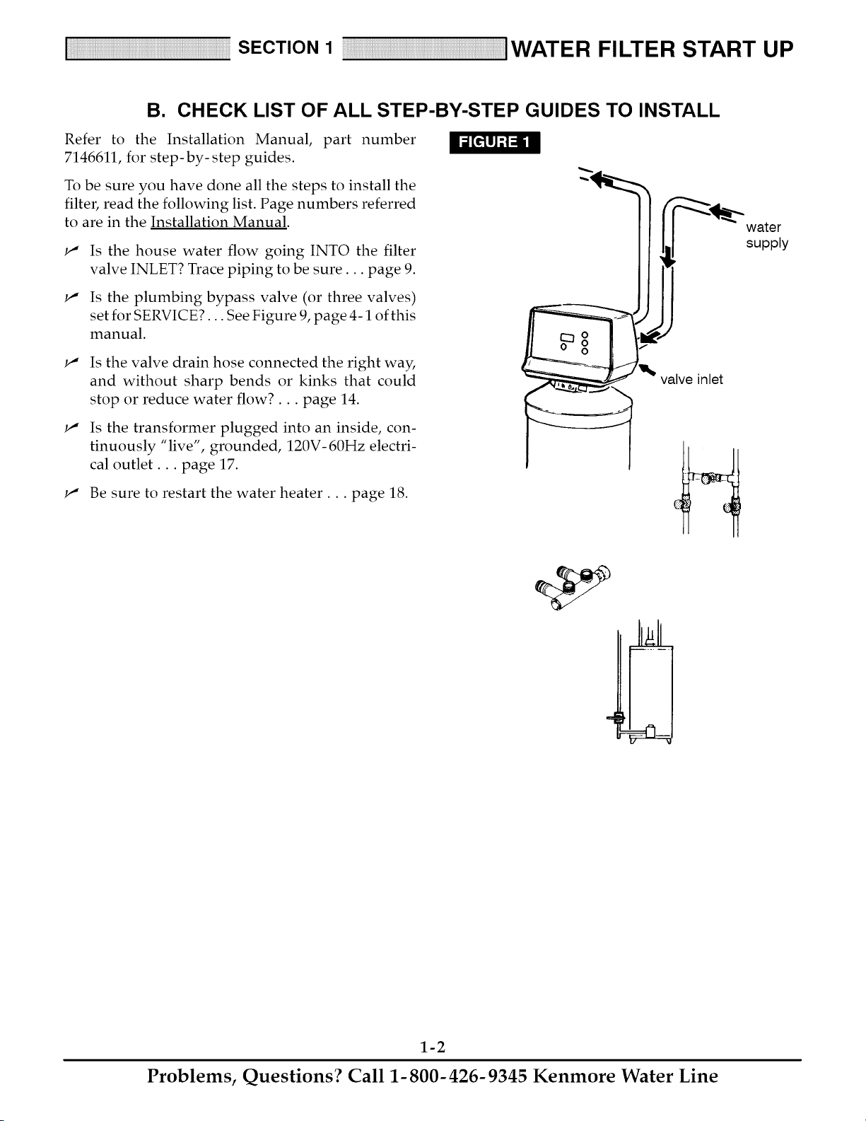
Refer to the Installation Manual, part number
7146611, for step-by-step guides.
To be sure you have done all the steps to install the
filter, read the following list. Page numbers referred
to are in the Installation Manual.
w"
w"
Is the house water flow going INTO the filter
valve INLET? Trace piping to be sure.., page 9.
Is the plumbing bypass valve (or three valves)
set for SERVICE?... See Figure 9, page 4-1 of this
manual.
w"
w"
Is the valve drain hose connected the right way,
and without sharp bends or kinks that could
stop or reduce water flow?.., page 14.
Is the transformer plugged into an inside, con-
tinuously "live", grounded, 120V- 60Hz electri-
cal outlet.., page 17.
w" Be sure to restart the water heater.., page 18.
valve inlet
water
supply
1-2
Problems, Questions? Call 1-800-426-9345 Kenmore Water Line
SECTION 1 IWATER FILTER START UP
C. PROGRAM THE TIMER
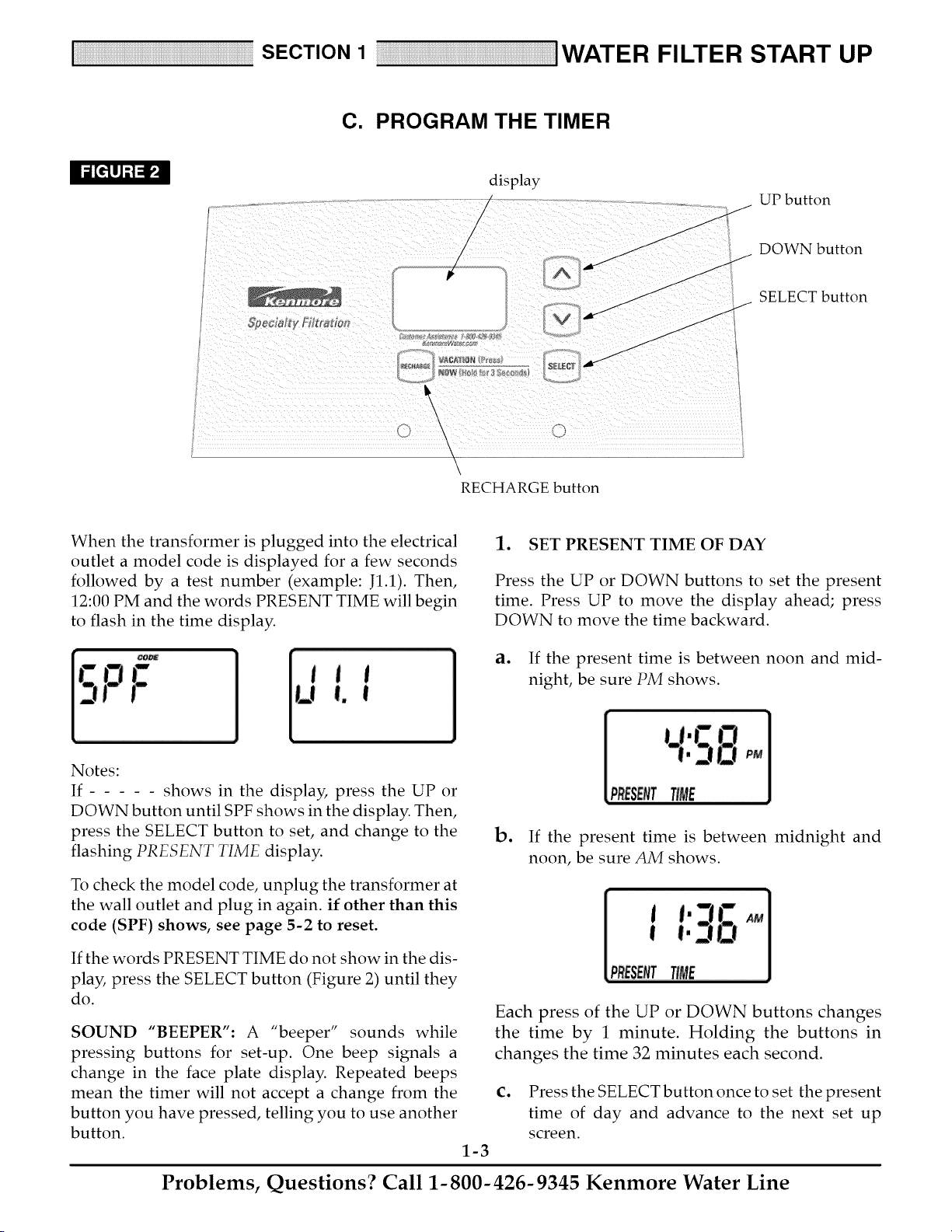
display
/
/
A
UP button
SDecia!_v Filtr_'_
V
\
i "> \ 2r
RECHARGE button
°J
DOWN button
SELECT button
When the transformer is plugged into the electrical
outlet a model code is displayed for a few seconds
followed by a test number (example: J1.1). Then,
12:00 PM and the words PRESENT TIME will begin
to flash in the time display.
1. SET PRESENT TIME OF DAY
Press the UP or DOWN buttons to set the present
time. Press UP to move the display ahead; press
DOWN to move the time backward.
a. If the present time is between noon and mid-
night, be sure PM shows.
Notes:
If shows in the display, press the UP or
DOWN button until SPF shows in the display. Then,
press the SELECT button to set, and change to the
flashing PRESENT TIME display.
To check the model code, unplug the transformer at
the wall outlet and plug in again, if other than this
code (SPF) shows, see page 5-2 to reset.
b. If the present time is between midnight and
noon, be sure AM shows.
If the words PRESENT TIME do not show in the dis-
play, press the SELECT button (Figure 2) until they
do.
SOUND "BEEPER": A "beeper" sounds while
pressing buttons for set-up. One beep signals a
change in the face plate display. Repeated beeps
mean the timer will not accept a change from the
button you have pressed, telling you to use another
button.
Each press of the UP or DOWN buttons changes
the time by 1 minute. Holding the buttons in
changes the time 32 minutes each second.
1-3
C. Press the SELECT button once to set the present
time of day and advance to the next set up
screen.
Problems, Questions? Call 1-800-426-9345 Kenmore Water Line
SECTION 1 iWATER FILTER START UP
C. PROGRAM THE TIMER
2. SET DAYS TO RECHARGE
This setting is the number of days the filter will go
between recharges. The default setting is 3 days,
with a maximum setting of 99.
3. SET RECHARGE TIME
The filter is factory set to begin recharge at 12:00 AM.
If a different recharge time is desired, or needed, do
the following.
- t
3.o
RECHarGE
ao Press the UP or DOWN buttons until the correct
number of days between recharges is shown in
the display.
b. Press the SELECT button once to set the days to
recharge and advance to the next set up screen.
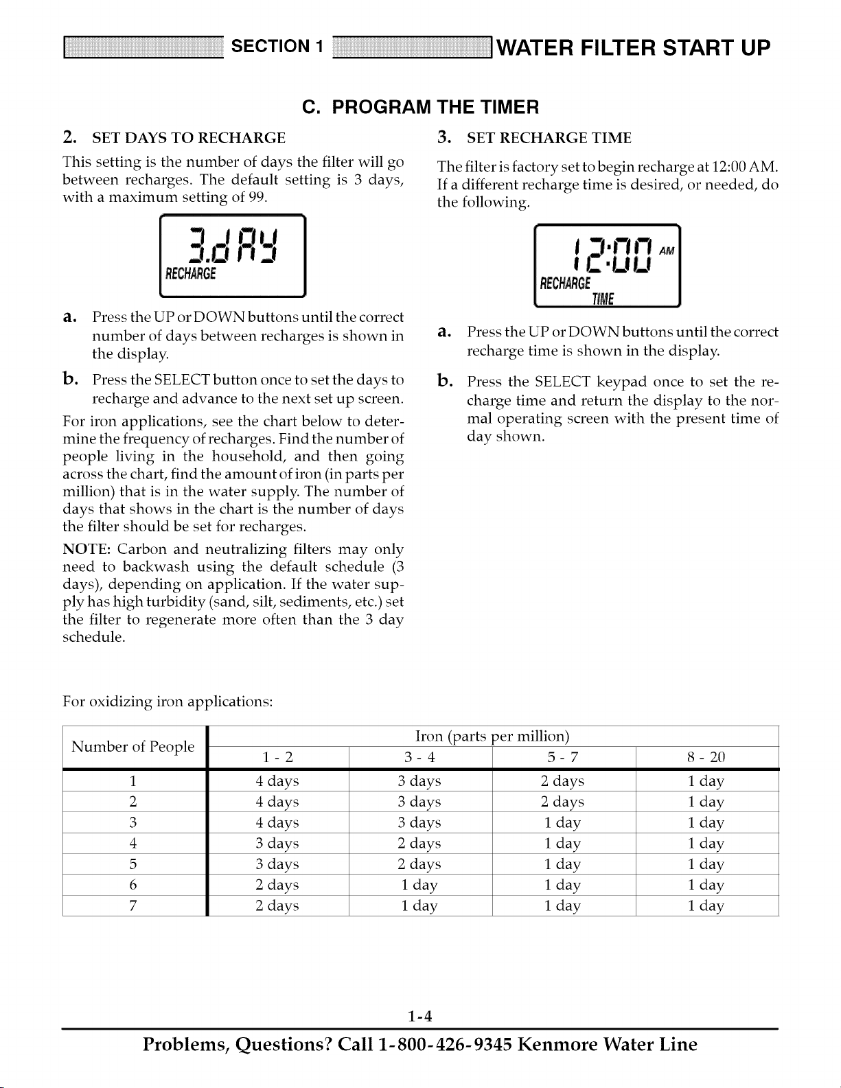
For iron applications, see the chart below to deter-
mine the frequency of recharges. Find the number of
people living in the household, and then going
across the chart, find the amount of iron (in parts per
million) that is in the water supply. The number of
days that shows in the chart is the number of days
the filter should be set for recharges.
NOTE: Carbon and neutralizing filters may only
need to backwash using the default schedule (3
days), depending on application. If the water sup-
ply has high turbidity (sand, silt, sediments, etc.) set
the filter to regenerate more often than the 3 day
schedule.
ao
Do
Press the UP or DOWN buttons until the correct
recharge time is shown in the display.
Press the SELECT keypad once to set the re-
charge time and return the display to the nor-
mal operating screen with the present time of
day shown.
For oxidizing iron applications:
Iron (parts per million)
Number of People 1- 2 3- 4 5- 7 8- 20
1 4 days 3 days 2 days 1 day
2 4 days 3 days 2 days 1 day
3 4 days 3 days 1 day 1 day
4 3 days 2 days 1 day 1 day
5 3 days 2 days 1 day 1 day
6 2 days 1 day 1 day 1 day
7 2 days 1 day 1 day 1 day
1-4
Problems, Questions? Call 1-800-426-9345 Kenmore Water Line
SECTION 1 IWATER FILTER START UP
D. SANITIZING THE WATER FILTER
Care is taken at the factory to keep your water filter
as clean and sanitary as possible. However, it is sug-
gested that the sanitizing procedure below is follo-
wed ,_1_
lo
o
o
Press and hold the RE-
CHARGE button until
"RECHARGE NOW"
begins to flash in the
display. Water will be-
gin to run from the drain hose as the filter valve
moves into backwash position.
After 5 to 10 minutes, press the RECHARGE
button again to move the valve into fast rinse
position (water stops, then begins to run from
drain hose again).
In about two minutes, put the bypass valve(s)
in bypass position (see Figure 9, page 4-1).
Then press the RECHARGE button once again
to return the filter to service position. Doing this
releases water pressure in the filter.
Carefully remove the large plastic clip at the fil-
ter valve inlet (pages 6-3 and 6-4). Pull the
valve adaptor from the valve inlet.
NOTE: If bypass valve, Sears Stock No. 42- 3437 is
installed, or if plumbing is too rigid to move, also
disconnect the outlet side and move the filter away
from plumbing.
4. Put one teaspoon (0.1 ounce) of calcium hypo-
chlorite into the valve inlet as far as possible.
NOTE: You can buy calcium hypochlorite in tablet
or granular form under trade names such as Perch-
loron and HTH.
o
Be sure the valve inlet is clean, for a good seal-
ing surface for the valve adaptor o-ring. Then,
reconnect plumbing to the filter. AFTER
INSTALLING THE LARGE PLASTIC CLIP,
PULL OUTWARD ON THE VALVE ADAPTOR
TO BE SURE IT'S PROPERLY HELD IN
PLACE.
o
SLOWLY, reposition the bypass valve(s) to ser-
vice, Figure 9, page 4-1. Open the nearest fil:
tered water faucet until you can smell chlorine,
then close.
7. Again, put the bypass valve(s) in bypass posi-
tion. Allow the filter to stand idle for about 45
minutes, while the chlorine sanitizes.
go
o
After 45 minutes, return the bypass valve(s) to
service position.
Repeat steps 1, la and lb to advance the filter to
backwash. The timer will automatically ad-
vance the filter through the backwash and fast
rinse cycles, during which the sanitizing bleach
is flushed to the drain.
NOTE: The backwash and fast rinse cycles take
about 30 minutes. When over, the timer automati-
cally returns the filter to service (water flow from the
drain hose stops).
10. Open house filtered water faucets and allow to
run until the chlorine odor is gone.
_ Recommended by the Water Quality Association. On some water sup-
plies, the water filter may need periodic disinfecting.
1-5
Problems, Questions? Call 1-800-426-9345 Kenmore Water Line
SECTION 2 HOW YOUR WATER FILTER WORKS
A. FACEPLATE TIMER FEATURES
S
E
C
T
N
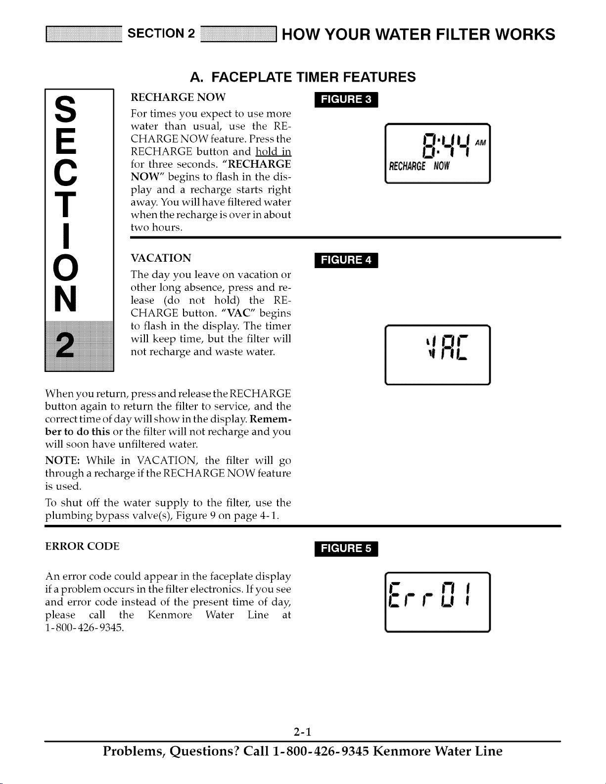
RECHARGE NOW
For times you expect to use more
water than usual, use the RE-
CHARGE NOW feature. Press the
RECHARGE button and hold in
for three seconds. "RECHARGE
NOW" begins to flash in the dis-
play and a recharge starts right
away. You will have filtered water
when the recharge is over in about
two hours.
VACATION
The day you leave on vacation or
other long absence, press and re-
lease (do not hold) the RE-
CHARGE button. "VAC" begins
to flash in the display. The timer
will keep time, but the filter will
not recharge and waste water.
When you return, press and release the RECHARGE
button again to return the filter to service, and the
correct time of day will show in the display. Remem-
ber to do this or the filter will not recharge and you
will soon have unfiltered water.
NOTE: While in VACATION, the filter will go
through a recharge if the RECHARGE NOW feature
is used.
To shut off the water supply to the filter, use the
plumbing bypass valve(s), Figure 9 on page 4-1.
ERROR CODE
An error code could appear in the faceplate display
if a problem occurs in the filter electronics. If you see
and error code instead of the present time of day,
please call the Kenmore Water Line at
1- 800- 426- 9345.
2-1
Problems, Questions? Call 1-800-426-9345 Kenmore Water Line

SECTION 2 HOW YOUR WATER FILTER WORKS
A. FACEPLATE TIMER FEATURES
The default settings for backwash (25 minutes) and
fast rinse (5 minutes) cycles of regeneration are fac-
tory set for maximum performance of the filter. Use
the following procedures to check for correct cycle
times, or to change if desired. However, only
trained technicians should change the time set-
tings.
ADJUSTABLE BACKWASH
Press and hold the SELECT button until the display
shows "000--", then press the SELECT button once
to advance to the Backwash time adjust screen.
TIME
Using the UP or DOWN buttons, adjust the back-
wash time from 0 minutes to 60 minutes.
ADJUSTABLE FAST RINSE
Press and hold the SELECT button until the display
shows "000- -", then press the SELECT button twice
to advance to the Fast Rinse time adjust screen.
TIMER "POWER-OUTAGE MEMORY"
If electrical power to the timer is interrupted, the
"memory" built into timer circuitry keeps time for 6
hours (minimum) or more. The display is blank and
the filter will not regenerate. When electrical power
comes on, one of two things will happen.
lo
o
The present time of day will show steady, mean-
ing the timer has not lost time.
The display will show a time, but it will be flash-
ing. The timer memory did not keep the time
setting and must be reset (page 1-3). If you do
not reset the time, regenerations will most likely
be at the wrong time of day.
NOTE: The flashing display is to remind you to reset
the timer.
NOTE: If the filter was in a recharge when power
was lost, it will now finish the cycle.
Using the UP or DOWN buttons, adjust the fast
rinse time from 0 minutes to 60 minutes.
2-2
Problems, Questions? Call 1-800-426-9345 Kenmore Water Line
SECTION 2 HOW YOUR WATER FILTER WORKS
B. FILTER APPLICATIONS
IMPORTANT: Sears water filters are sometimes installed alone in the water system, but most often other wa-
ter treating equipment is needed. Always be sure to have your water tested by a qualified testing laboratory.
If you need help, ask at your Sears store, or call the Kenmore Water Line, 1- 800- 426- 9345.
CLARIFYING FILTER
A Sears Clarifying Filter takes sediments such as
dirt, sand, silt, clay and fine organic matter out of
water. You can see sediments in water by filling a
clear drinking glass. When held up to light, you can
see the particles floating in the water, or settled to the
bottom of the glass. The filter is filled with "filter ag-
gregate" mineral that traps and holds the sediments
as the water flows through it.
The Clarifier is sometimes installed alone but is
often followed by a water softener. Besides soften-
ing the water, the water softener catches sediments
that may get through the filter.
NOTE: If you install the clarifying filter along with
a Sears Solution Dispensing System, Read the dis-
pensing system owners manual for treating a pri-
vate well before installing.
NEUTRALIZER FILTER
All water, when chemically analyzed, is either acid,
neutral or base (alkaline). To measure this, the water
is given a pH value between 0 and 14. Water is acid
if the pH is from 0 to 6.9. At 7, the water is neutral,
and above that the water is alkaline.
Your Sears neutralizing filter treats acid water when
the pH is from 6.0 to 6.7. A Sears Cartridge Filter
with a Phosphate Crystal Cartridge is often used to
treat water with a pH of 6.8 to 6.9. Acid water short-
ens the life of iron pipe, corrodes copper and brass
pipe, and makes green stains on pluming fixtures. In
time, it will even etch porcelain enamel. The filter
has a special mineral (Neutralite) that raises the pH
of the water to help reduce these acid water prob-
lems.
TASTE & ODOR FILTER
A Sears taste & odor filter removes most tastes,
odors and certain organic colors from water. Bad
tastes and odors come from many different causes.
Often, one causes the other. The activated carbon
bed, in the taste & odor filter, has a great ability for
taking tastes and odors out of water.
NOTE: If your water has hydrogen sulfide (rotten
egg taste or odor), be sure to get a qualified testing
laboratories recommendation for proper treatment.
2-3
Problems, Questions? Call 1-800-426-9345 Kenmore Water Line
SECTION 2 HOW YOUR WATER FILTER WORKS
C. FILTERED WATER SERVICE, AND BACKWASH
CLARIFIER FILTER
SERVICE
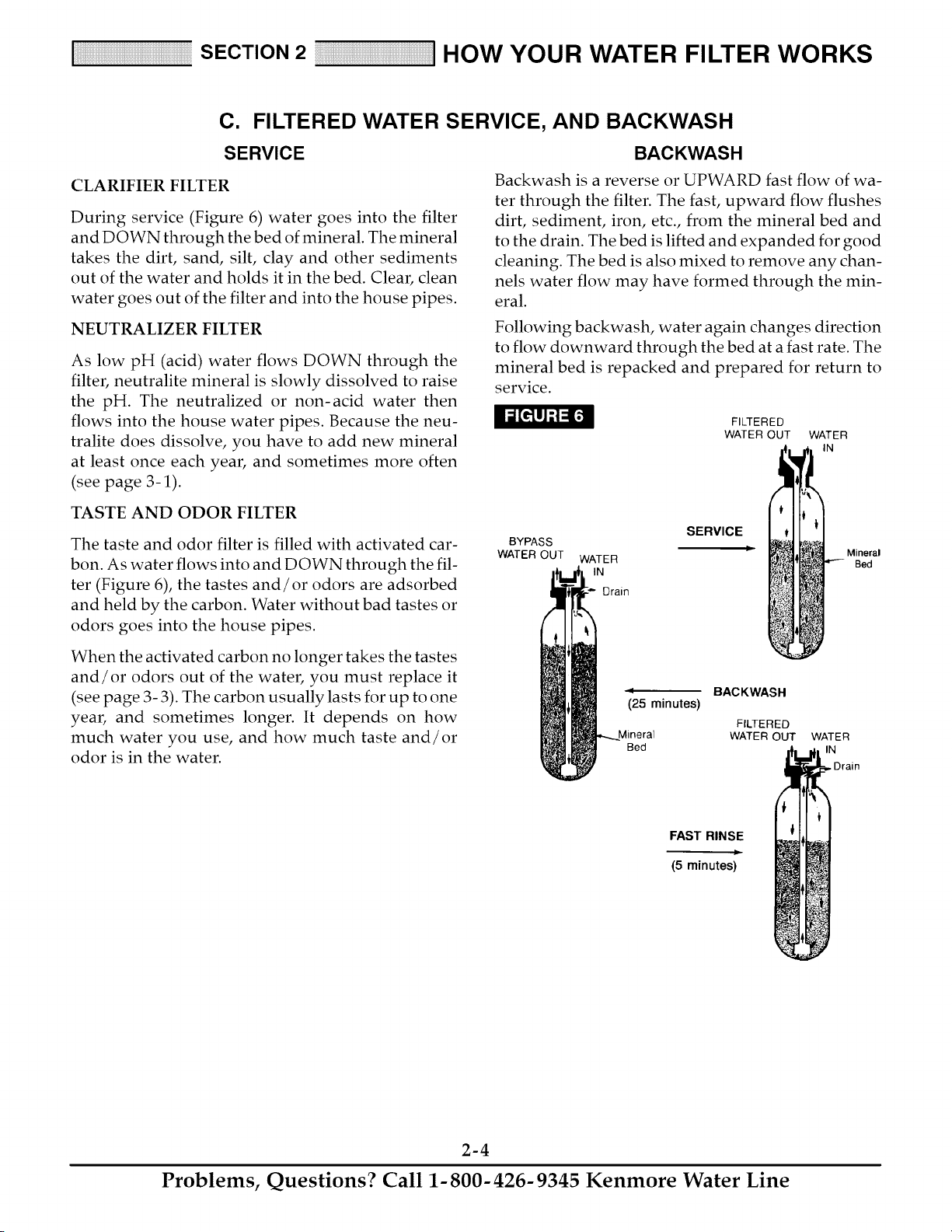
During service (Figure 6) water goes into the filter
and DOWN through the bed of mineral. The mineral
takes the dirt, sand, silt, clay and other sediments
out of the water and holds it in the bed. Clear, clean
water goes out of the filter and into the house pipes.
NEUTRALIZER FILTER
As low pH (acid) water flows DOWN through the
filter, neutralite mineral is slowly dissolved to raise
the pH. The neutralized or non-acid water then
flows into the house water pipes. Because the neu-
tralite does dissolve, you have to add new mineral
at least once each year, and sometimes more often
(see page 3-1).
BACKWASH
Backwash is a reverse or UPWARD fast flow of wa-
ter through the filter. The fast, upward flow flushes
dirt, sediment, iron, etc., from the mineral bed and
to the drain. The bed is lifted and expanded for good
cleaning. The bed is also mixed to remove any chan-
nels water flow may have formed through the min-
eral.
Following backwash, water again changes direction
to flow downward through the bed at a fast rate. The
mineral bed is repacked and prepared for return to
service.
FILTERED
WATER OUT WATER
IN
TASTE AND ODOR FILTER
The taste and odor filter is filled with activated car-
bon. As water flows into and DOWN through the fil-
ter (Figure 6), the tastes and/or odors are adsorbed
and held by the carbon. Water without bad tastes or
odors goes into the house pipes.
When the activated carbon no longer takes the tastes
and/or odors out of the water, you must replace it
(see page 3- 3). The carbon usually lasts for up to one
year, and sometimes longer. It depends on how
much water you use, and how much taste and/or
odor is in the water.
BYPASS
WATER OUT
WATER
IN
Drain
SERVICE
Ii
_25 minutes)
Mineral
Bed
BACKWASH
FILTERED
WATER OUT
Mineral
Bed
WATER
IN
, Drain
FAST RINSE
(5minutes)
2-4
Problems, Questions? Call 1-800-426-9345 Kenmore Water Line
S
E
C
T
N
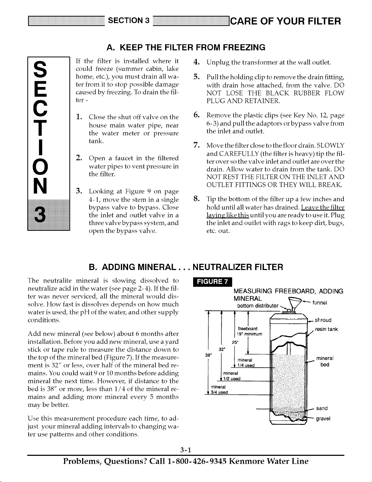
A. KEEP THE FILTER FROM FREEZING
If the filter is installed where it
could freeze (summer cabin, lake
home, etc.), you must drain all wa-
ter from it to stop possible damage
caused by freezing. To drain the fil-
ter -
.
5.
Unplug the transformer at the wall outlet.
Pull the holding clip to remove the drain fitting,
with drain hose attached, from the valve. DO
NOT LOSE THE BLACK RUBBER FLOW
PLUG AND RETAINER.
.
.
.
Close the shut off valve on the
house main water pipe, near
the water meter or pressure
tank.
Open a faucet in the filtered
water pipes to vent pressure in
the filter.
Looking at Figure 9 on page
4-1, move the stem in a single
bypass valve to bypass. Close
the inlet and outlet valve in a
three valve bypass system, and
open the bypass valve.
6. Remove the plastic clips (see Key No. 12, page
6- 3) and pull the adaptors or bypass valve from
the inlet and outlet.
. Move the filter close to the floor drain. SLOWLY
and CAREFULLY (the filter is heavy) tip the fil-
ter over so the valve inlet and outlet are over the
drain. Allow water to drain from the tank. DO
NOT REST THE FILTER ON THE INLET AND
OUTLET FITTINGS OR THEY WILL BREAK.
.
Tip the bottom of the filter up a few inches and
hold until all water has drained. Leave the filter
laying like this until you are ready to use it. Plug
the inlet and outlet with rags to keep dirt, bugs,
etc. out.
B. ADDING MINERAL... NEUTRALIZER FILTER
The neutralite mineral is slowing dissolved to
neutralize acid in the water (see page 2- 4). If the fil-
ter was never serviced, all the mineral would dis-
solve. How fast is dissolves depends on how much
water is used, the pH of the water, and other supply
conditions.
Add new mineral (see below) about 6 months after
installation. Before you add new mineral, use a yard
stick or tape rule to measure the distance down to
the top of the mineral bed (Figure 7). If the measure-
ment is 32" or less, over half of the mineral bed re-
mains. You could wait 9 or 10 months before adding
mineral the next time. However, if distance to the
bed is 38" or more, less than 1/4 of the mineral re-
mains and adding more mineral every 5 months
may be better.
Use this measurement procedure each time, to ad-
just your mineral adding intervals to changing wa-
ter use patterns and other conditions.
MEASURING FREEBOARD, ADDING
M NERAL L----_ .....
bottom distributor _" funnel
:!_i:.!i!:ii'!:i.i?q:!_i:i!_i:i:!;i
•_._!_:f _:._:_ ..................
_ shroud
resin tank
/
..- mineral
bed
...- sand
gravel
3-1
Problems, Questions? Call 1-800-426-9345 Kenmore Water Line

B. ADDING MINERAL... NEUTRALIZER FILTER
STEPS TO ADD MINERAL
.
Press the RECHARGE button and hold in for
three seconds until "RECHARGE NOW" be-
gins to flash in the display.
.
When water begins to flow from the valve drain
hose, place the bypass valve(s) in BYPASS posi-
tion, see Figure 9, page 4-1.
CAUTION: BE SURE TO DO STEPS 1 AND 2 AS
INSTRUCTED, TO RELIEVE WATER PRESSURE
IN THE TANK.
3. Unplug the transformer at the wall outlet.
.
6. Remove the o- rings (3) and top distributor from
the top of the tank.
7. To make room for the new mineral, use a hose
to siphon water from the tank.
8. Use a large neck funnel, add new mineral into
the tank.
.
Carefully, pull the two clips (Key No. 12, page
6-3) at the inlet and outlet fittings. Slide the
adaptors, or bypass valve, from the filter valve.
Referring to Figure 8, remove the clamp retain-
ers (2) and clamp sections (2) that hold the valve
to the tank. Lift upward to remove the valve.
top
distributor
bottom
o-ring seal (THIN)
-3/4" I.D. x 3" O.D.
3-2
IMPORTANT: DO NOT ADD MINERAL INTO
THE BOTTOM DISTRIBUTOR. Temporarily plug
the distributor tube to prevent accidental mineral
spills into it.
DO NOT OVERFILL the tank. Freeboard area (see
Figure 7) is needed for proper backwashing. If you
have mineral remaining, you can use it the next time
you refill the tank.
.
Use water to flush the tank top opening. Then,
replace the top distributor and three o-rings. Be
sure to locate o-ring seals correctly, Figure 8.
10. Carefully, install the valve assembly and retain-
ing clamps. DOUBLE CHECK TO BE SURE
CLAMPS AND RETAINERS ARE SECURELY
FASTENED IN PLACE.
11.
Referring to your installation manual, recon-
nect the filter to the plumbing. BE SURE THE
PLUMBING IS HELD FIRMLY IN PLACE, IN
THE VALVE INLET AND OUTLET.
12. Place the valve drain hose at the drain point and
secure into place.
13. Return the plumbing bypass valve(s) to SER-
VICE position.
14. Plug the transformer into the wall outlet. The
filter will complete the backwash cycle started
in step 1 and will automatically return to ser-
vice.
Problems, Questions? Call 1-800-426-9345 Kenmore Water Line
C. REPLACING MINERAL... TASTE & ODOR FILTER
Average life of the activated carbon mineral bed is
about one year (see page 2-4). It's time to replace the
bed when the tastes and/or odors begin to return in
the water supply. Do the following.
STEPS TO REMOVE AND ADD MINERAL
. Press the RECHARGE button and hold in for
three seconds until "RECHARGE NOW" be-
gins to flash in the display.
.
.
Stand the tank upright and replace the bottom
distributor assembly. Temporarily, plug the top
end of the distributor (use a rag, etc.) to prevent
accidental mineral spills into it.
Using a large neck funnel (Figure 7), first add 17
lbs. of gravel, followed by 10 lbs. of filter sand.
Next, add the 1 cu. ft. of activated carbon. Use
water sparingly to assist carbon flow through
the funnel.
.
When water begins to flow from the valve drain
hose, place the bypass valve(s) in BYPASS posi-
tion, see Figure 9, page 4-1.
CAUTION: BE SURE TO DO STEPS 1 AND 2 AS
INSTRUCTED, TO RELIEVE WATER PRESSURE
IN THE TANK.
NOTE: Be sure the bottom distributor is centered in
the tank while adding mineral.
10.
Use water to flush the tank top opening. Then,
replace the top distributor and three o-rings. Be
sure to locate o-ring seals correctly, Figure 8,
page 3- 2.
.
4.
.
.
.
Unplug the transformer at the wall outlet.
Carefully, pull the two clips (Key No. 12, page
6-3) at the inlet and outlet fittings. Slide the
adaptors, or bypass valve, from the filter valve.
Referring to Figure 8, page 3-2, remove the
clamp retainers (2) and clamp sections (2) that
hold the valve to the tank. Lift upward to re-
move the valve.
Remove the o- rings (3) and top distributor from
the top of the tank.
Next to a floor drain, carefully tip the tank over,
catching the used carbon in a burlap sack or oth-
er suitable container. Remove the bottom dis-
tributor assembly, and flush the inside of the
tank with water.
11.
12.
13.
14.
15.
Carefully, install the valve assembly and retain-
ing clamps. DOUBLE CHECK TO BE SURE
CLAMPS AND RETAINERS ARE SECURELY
FASTENED IN PLACE.
Referring to your installation manual, recon-
nect the filter to the plumbing. BE SURE THE
PLUMBING IS HELD FIRMLY IN PLACE,
THE THE VALVE INLET AND OUTLET.
Place the valve drain hose at the drain point and
secure in place.
Return the plumbing bypass valve(s) to SER-
VICE position.
Plug the transformer into the wall outlet. The
filter will complete the backwash cycle, started
in step 1, and will automatically return to ser-
vice.
CAUTION: HANDLE THE TANK CAREFULLY. IT
IS VERY HEAVY WHEN FULL OF WATER AND
CARBON. DO NOT ATTEMPT TO LIFT IT BY
YOURSELF. DO NOT DROP AND BREAK THE
TANK.
NOTE: All new carbon mineral contains some
smaller that normal particles called "fines". Back-
washing the filter removes the fines. If, after the
backwash in step 15 is over, fines are still in the fil-
tered water, repeat step 1 for added backwashing.
3-3
Problems, Questions? Call 1-800-426-9345 Kenmore Water Line

D. BEFORE YOU CALL FOR SERVICE...HELPFUL HINTS CHECKLIST
PROBLEM
FILTER WILL NOT BACKWASH
LOW WATER PRESSURE AT
HOUSE FAUCETS
FILTERED WATER CONTAINS SED-
IMENTS, IRON, DIRT, SAND, ETC.
NEUTRALIZER FILTER ONLY: FIL-
TER WATER IS ACID OR PARTLY
ACID
NOTE: Trace plumbing to be sure
faucet(s) is on filtered water service.
TASTE & ODOR FILTER ONLY: FIL-
TERED WATER HAS BAD TASTE
AND/OR ODOR
NOTE: Trace plumbing to be sure
faucet(s) is on filtered water service.
CAUSE
Manual bypass valve(s) in bypass
position
Transformer uplugged at wall outlet,
power cable disconnected from
electronic board, fuse blown/circuit
breaker popped, or circuit switched
off.
CORRECTION
See Figure 9, page 4-1. Move stem
in a single bypass valve to SER-
VICE. In a three valve bypass, open
the inlet and outlet valves, close the
bypass valve.
Check for loss of power and correct.
Reset the times and use the RE-
CHARGE NOW feature, see page.
Also see "Electric Power Outlet For
Your Filter" page 17, in the installa-
tion manual.
Timer in the vacation (VAC) position Press the RECHARGE button once
to return the filter to service, see
page 2-1.
An error code shows in the face- See page 2-1.
plate display
Backwash flow washer plugged See Key No. 9, page 6-3, and re-
move drain hose adaptor to clean.
Drain hose plugged, kinked or bent
Well pump pressure switch set too
low
Backwash needed more often to
keep filter mineral clean
See all conditions under Filter Will
Not Backwash, above.
Manual bypass valve(s) is bypass
position
Filter low on neutralite mineral
Manual bypass valve(s) is bypass
position
Activated carbon mineral bed is ex-
hausted
Straighten hose, or remove and
clean.
Adjust to a minimum of 20 psi.
See page 1-4 to program more
backwashes.
See above.
See above.
Add new mineral, see page 3-2.
See above.
Replace mineral, see page 3-3.
3-4
Problems, Questions? Call 1-800-426-9345 Kenmore Water Line
SECTION 4 I OTHER THINGS TO KNOW
S
E
C
T
N
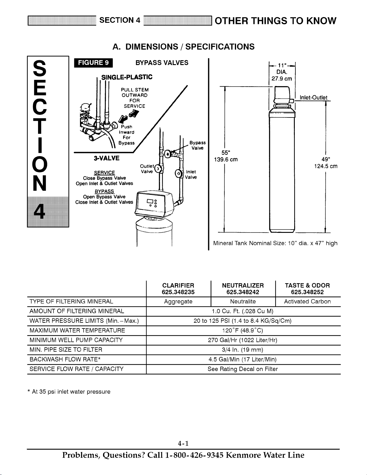
A. DIMENSIONS / SPECIFICATIONS
BYPASS VALVES
SINGLE-PLASTIC
PULL STEM
OUTWARD
FOR
SERVICE
Push
Inward
For !
Bypass
3-VALVEsERVICE !
Valve£ C
Close Bypass Valve
Open Inlet & Outlet Valves
YS
Open Bypass Valve
Close Inlet & Outlet Valves
Bypass
I Valve
Inlet
Valve
55"
139.6 cm
.9 c_l
Inlet-Outlet
49"
124.5 cm
Mineral Tank Nominal Size: 10" dia. x 47" high
TYPE OF FILTERING MINERAL
AMOUNT OF FILTERING MINERAL
WATER PRESSURE LIMITS (Min.-Max.)
MAXIMUM WATER TEMPERATURE
MINIMUM WELL PUMP CAPACITY
MIN. PIPE SIZE TO FILTER
BACKWASH FLOW RATE*
SERVICE FLOW RATE / CAPACITY
CLARIFIER
625.348235
Aggregate
NEUTRALIZER TASTE & ODOR
625.348242 625.348252
Neutralite Activated Carbon
1.0 Cu. Ft. (.028 Cu M)
20 to 125 PSI (1.4 to 8.4 KG/Sq/Cm)
120°F (48.9°C)
270 Gal/Hr (1022 Liter/Hr)
3/4 In. (19 mm)
4.5 Gal/Min (17 Liter/Min)
See Rating Decal on Filter
* At 35 psi inlet water pressure
4-1
Problems, Questions? Call 1-800-426-9345 Kenmore Water Line
SECTION 5 SERVICE mECH. INFORMATION
S
C
T
N
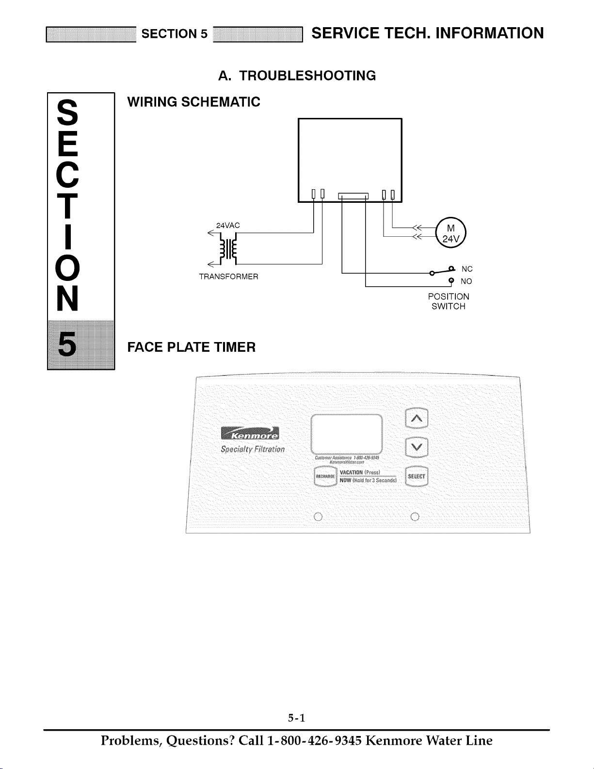
A. TROUBLESHOOTING
WIRING SCHEMATIC
24VAC
TRANSFORMER
J_. NC
NO
POSITION
SWITCH
FACE PLATE TIMER
_v
A
NgW F_oI_ _c_¢3 _c0#_s
5-1
Problems, Questions? Call 1-800-426-9345 Kenmore Water Line
SECTION 5 SERVICE mECH. INFORMATION
A. TROUBLESHOOTING
ALWAYS MAKE THESE INITIAL CHECKS FIRST
1. Does the time display show the correct time of
day?
...If display is blank, check power source to the filter.
...If time is flashing, power was off for over two
days. The filter resumes normal operation but re-
charges occur at the wrong time.
2. Plumbing bypass valve(s) must be in SERVICE
position (see Figure 9, page 4-1).
3. The inlet and outlet pipes must connect to the fil-
ter inlet and outlet respectively.
4. Is the transformer plugged into a "live" grounded
wall outlet, and the power cable fastened securely?
5. The valve drain hose must be free of kinks and
sharp bends.
If you do not find the problem after making the ini-
tial checks, do the MANUAL ADVANCE DIAG-
NOSTICS.
MANUAL INITIATED ELECTRONICS
DIAGNOSTIC
1. To enter diagnostics, press and hold the SELECT
button until (000- -) shows in the display.
Use the RECHARGE button to manually advance
the valve into each cycle and check correct switch
operation.
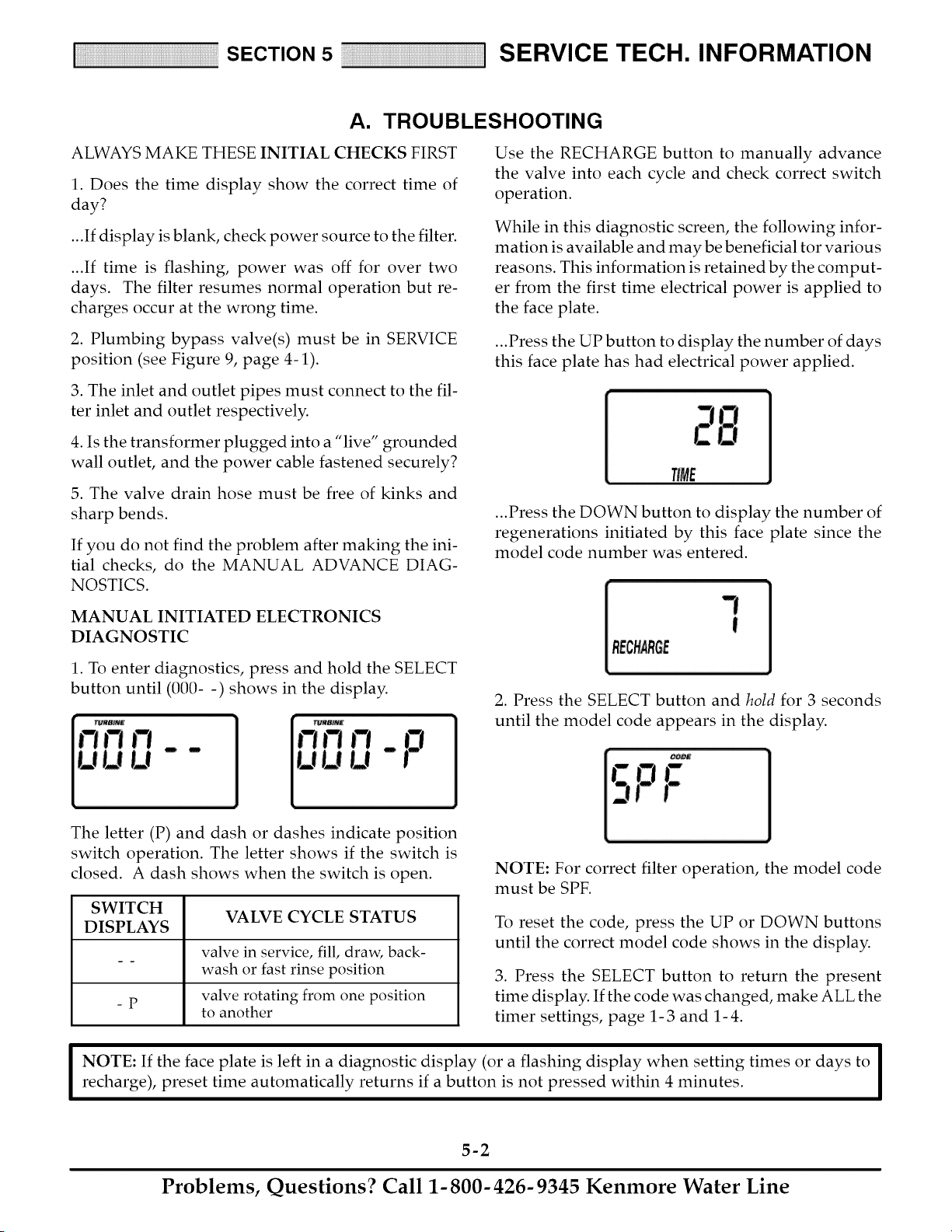
While in this diagnostic screen, the following infor-
mation is available and may be beneficial tor various
reasons. This information is retained by the comput-
er from the first time electrical power is applied to
the face plate.
...Press the UP button to display the number of days
this face plate has had electrical power applied.
TIME
...Press the DOWN button to display the number of
regenerations initiated by this face plate since the
model code number was entered.
RECHARGE
2. Press the SELECT button and hold for 3 seconds
until the model code appears in the display.
The letter (P) and dash or dashes indicate position
switch operation. The letter shows if the switch is
closed. A dash shows when the switch is open.
SWITCH
VALVE CYCLE STATUS
DISPLAYS
valve in service, fill, draw, back-
wash or fast rinse position
valve rotating from one position
-p
to another
NOTE: For correct filter operation, the model code
must be SPF.
To reset the code, press the UP or DOWN buttons
until the correct model code shows in the display.
3. Press the SELECT button to return the present
time display. If the code was changed, make ALL the
timer settings, page 1-3 and 1-4.
I OTE: If the face plate is left in a diagnostic display (or a flashing display when setting times or days to I
recharge), preset time automatically returns if a button is not pressed within 4 minutes.
I
5-2
Problems, Questions? Call 1-800-426-9345 Kenmore Water Line
SECTION 5 SERVICE mECH. INFORMATION
A. TROUBLESHOOTING
MANUAL ADVANCE DIAGNOSTICS
Use the following procedures to advance the filter
valve through the regeneration cycles to check op-
eration.
Remove the top cover to observe cam and switch op-
eration during valve rotation.
DISPLAY MUST SHOW TIME AND DAY
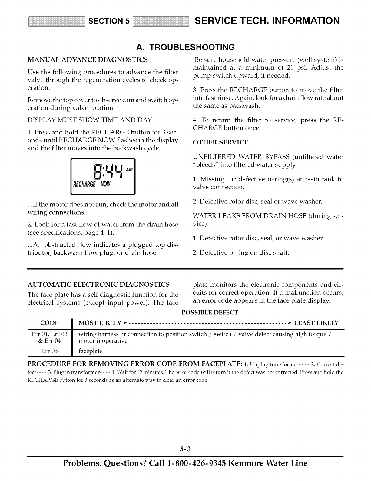
1. Press and hold the RECHARGE button for 3 sec-
onds until RECHARGE NOW flashes in the display
and the filter moves into the backwash cycle.
Be sure household water pressure (well system) is
maintained at a minimum of 20 psi. Adjust the
pump switch upward, if needed.
3. Press the RECHARGE button to move the filter
into fast rinse. Again, look for a drain flow rate about
the same as backwash.
4. To return the filter to service, press the RE-
CHARGE button once.
OTHER SERVICE
UNFILTERED WATER BYPASS (unfiltered water
"bleeds" into filtered water supply.
1. Missing or defective o-ring(s) at resin tank to
valve connection.
...If the motor does not run, check the motor and all
wiring connections.
2. Look for a fast flow of water from the drain hose
(see specifications, page 4-1).
...An obstructed flow indicates a plugged top dis-
tributor, backwash flow plug, or drain hose.
2. Defective rotor disc, seal or wave washer.
WATER LEAKS FROM DRAIN HOSE (during ser-
vice)
1. Defective rotor disc, seal, or wave washer.
2. Defective o-ring on disc shaft.
AUTOMATIC ELECTRONIC DIAGNOSTICS
The face plate has a self diagnostic function for the
electrical systems (except input power). The face
CODE
Err 01, Err 03
& Err 04
Err 05
plate monitors the electronic components and cir-
cuits for correct operation. If a malfunction occurs,
an error code appears in the face plate display.
POSSIBLE DEFECT
MOST LIKELY _ .... _ LEAST LIKELY
wiring harness or connection to position switch / switch / valve defect causing high torque /
motor inoperative
faceplate
PROCEDURE FOR REMOVING ERROR CODE FROM FACEPLATE: 1. Unplug transformer .... 2. Correct de-
fect .... 3. Plug in transformer .... 4. Wait for 12 minutes. The error code will return if the defect was not corrected. Press and hold the
RECHARGE button for 3 seconds as an alternate way to clear an error code.
5-3
Problems, Questions? Call 1-800-426-9345 Kenmore Water Line
SECTION 5 SERVICE mECH. INFORMATION
A. TROUBLESHOOTING
NEUTRAUZER FILTER
FILTERED WATER IS ACID
(LOW pH)
TASTE & ODOR RLTER
FILTERED WATER bIAS TASTE
AND/OR ODOR
NEEDS REFILL OF i I NEEDS REPLACEMENT
NEUTRALITE M INERAL OF ACTIVATED CARBON
MINERAL
ALL FILTERS I
FILTEREDWATER CONTAINSSEDIMENTS,
(SAND, StLT,,DIRT, ETC.) OR IRON
!
I IRONINWATERREQUIRES I
OTHERWATERCONDITIONING
(HAVEWATERANALYZED)
1
V,SUA OHEO S
1. Is raw water pipe plumbed to valve inlet?
i Is plumbing bypassvalve(s) in service?
Is valvedrainhoseunobstructed?
TIMER SHOWSWRONGTIME I
AND DAY AND/0B S FLASH NG I
=
Electrical power was off. I
i
Reset all timer programming
I
Investigatereasonfor
powerloss. Besure out-
let for filter cannotbe
switchedoff.
J Do ManualAdvance I
Diagnosticto verify pro-
per function.
f
f f
PROGRAMMINGOK I TOOFEW BACK-
i
FOR FAMILY NEEDS I WASHESPRO-
GRAMMED.
1. Leakingfaucetor REPROGRAM_ Do ManualAdvanceDiagnosticto l
stool I _ ver fy proper function.
I
2. Filteredwater usebl
atoutaidefaucetsLI DOMANUALADVANCETOI /
3. Otherunusualfil- r,P-i FILLCYCLE- CHECKFILL
tered waterusage/I FLOWTO SOLUTONB0rFLE /
/
TIMER DISPLAYSHOWS CORRECT
TIME AND DAY, AND IS STEADY
i
OBSERVEVALVE CAM POSITION
l
I'N ERV, EPDS,,,ONI [ OTINSERV,OEPOSITIO I
TESTWATERATFILTEREDWATER / 1. Wiring harness has loose
FAUCETCLOSESTTO FILTER J connections, or defective
t 2. Switch defective
_ 3. Valve motor inoperative
t NOSED'MENTS1 WATER CONTAIN 4
INWATER I SEDIMENTS 1
I CHECKPROGRAMMINGI
Filterregeneratedsince
customer railed. Checkfor
correctregenerationpro-
gramming.
f
[ Do Manual Advance Diagnostic I
to verify proper function.
/
/
/
[TIMERDISPLAYDLANKI
÷
Check electrical power
to timer (outlet, trans-
former, all connections)
t
IPOWEROKAYI
FACEPLATE
DEFECTVE
/
/
/
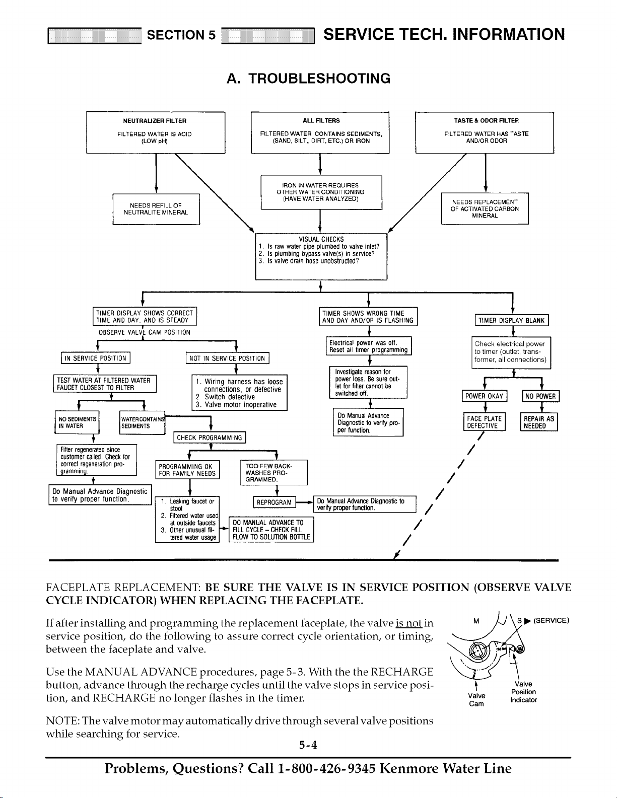
FACEPLATE REPLACEMENT: BE SURE THE VALVE IS IN SERVICE POSITION (OBSERVE VALVE
CYCLE INDICATOR) WHEN REPLACING THE FACEPLATE.
If after installing and programming the replacement faceplate, the valve is not in M
service position, do the following to assure correct cycle orientation, or timing,
between the faceplate and valve.
S • (SERVICE)
Use the MANUAL ADVANCE procedures, page 5- 3. With the the RECHARGE
button, advance through the recharge cycles until the valve stops in service posi-
tion, and RECHARGE no longer flashes in the timer. Valve
Cam
NOTE: The valve motor may automatically drive through several valve positions
while searching for service.
5-4
Valve
Position
Indicator
Problems, Questions? Call 1-800-426-9345 Kenmore Water Line
SECTION 5 SERVICE mECH. INFORMATION
B. ROTARY VALVE SERVICE
BEFORE WORKING ON THE VALVE, TURN OFF
THE WATER SUPPLY AND DISCONNECT FROM
ELECTRICAL POWER. TO RELIEVE PRESSURE.
... THREE VALVE BYPASS: Close the inlet and open
a filtered water faucet. Then close the outlet valve
and open the bypass valve.
... SEARS SPECIAL BYPASS: Slide the bypass valve
stem to bypass position. Loosen the three hex head
screws (see (A_ in drawing) toward the backside of
the valve to allow pressure water to bleed out (catch
water with a rag).
DISASSEMBLY
To remove a part or group of parts, refer to the valve
drawing. A common screwdriver or nut driver, Phil-
lips screwdriver and pliers are the only tools needed
to completely disassemble.
SERVICING THE VALVE
Inspect all o- rings, seals and gaskets for wear or de-
fects.
Inspect the bottom surface of the rotor and disc for
scratches, chips or wear.
NOTE: If a replacement is needed, be sure to use the
current replacement part.
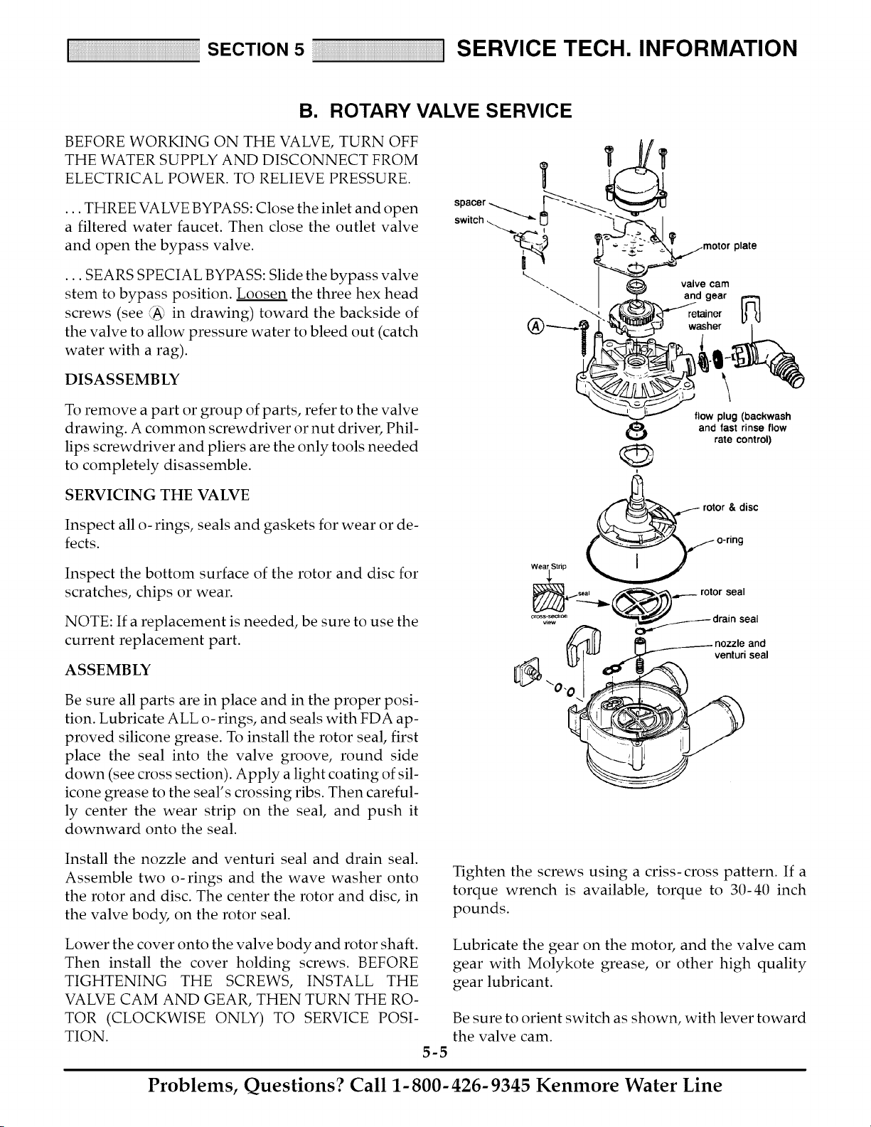
ASSEMBLY
Be sure all parts are in place and in the proper posi-
tion. Lubricate ALL o-rings, and seals with FDA ap-
proved silicone grease. To install the rotor seal, first
place the seal into the valve groove, round side
down (see cross section). Apply a light coating of sil-
icone grease to the seal's crossing ribs. Then careful-
ly center the wear strip on the seal, and push it
downward onto the seal.
\
flow plug (backwash
and fast rinse flow
rate control)
rotor & disc
venturi seal
Install the nozzle and venturi seal and drain seal.
Assemble two o-rings and the wave washer onto
the rotor and disc. The center the rotor and disc, in
the valve body, on the rotor seal.
Lower the cover onto the valve body and rotor shaft.
Then install the cover holding screws. BEFORE
TIGHTENING THE SCREWS, INSTALL THE
VALVE CAM AND GEAR, THEN TURN THE RO-
TOR (CLOCKWISE ONLY) TO SERVICE POSI-
TION.
5-5
Tighten the screws using a criss-cross pattern. If a
torque wrench is available, torque to 30-40 inch
pounds.
Lubricate the gear on the motor, and the valve cam
gear with Molykote grease, or other high quality
gear lubricant.
Be sure to orient switch as shown, with lever toward
the valve cam.
Problems, Questions? Call 1-800-426-9345 Kenmore Water Line
SECTION 5 SERVICE mECH. INFORMATION
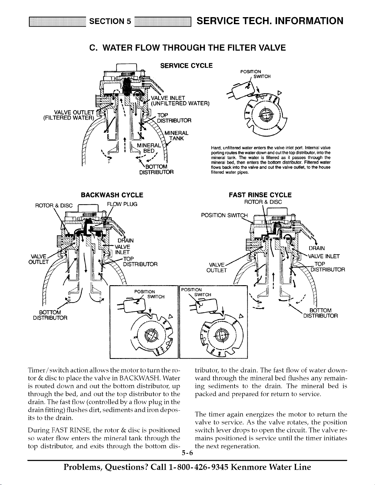
C. WATER FLOW THROUGH THE FILTER VALVE
ERVICE CYCLE ._ _1:>
POSITION
SWITCH
E INLET
VALVE OUTLET _j
i I_ MINERAL_ " the valve Internal valve
,_ _ 0 porting routes the water down and out the top distributor, intothe
BED • _ Hard, unfiltered water enters inlet port.
'*,_p 4_,._ _./ _ mineral tank. The water is filtered as it passes through the
_, mineral bed, then enters the bottom distributor. Filtered water
BOTTOM flows back into the valve and out the valve outlet, to the house
DISTRIBUTOR filtered water pipes.
ROTOR & DISC
\
BACKWASH CYCLE
PLUG
FAST RINSE CYCLE
ROTOR& DISC
POSITION SWITCH
OUTLET
DRAIN
INLET
INLET
DISTRIBUTOR TOP
OUTLET DISTRIBUTOR
BOTTOM
DISTRIBUTOR
POSITION
SWITCH
POSITION
SWITCH
/
:_,_ BOTTOM
DISTRIBUTOR
Timer/switch action allows the motor to turn the ro-
tor & disc to place the valve in BACKWASH. Water
is routed down and out the bottom distributor, up
through the bed, and out the top distributor to the
drain. The fast flow (controlled by a flow plug in the
drain fitting) flushes dirt, sediments and iron depos-
its to the drain.
During FAST RINSE, the rotor & disc is positioned
so water flow enters the mineral tank through the
top distributor, and exits through the bottom dis-
5-6
tributor, to the drain. The fast flow of water down-
ward through the mineral bed flushes any remain-
ing sediments to the drain. The mineral bed is
packed and prepared for return to service.
The timer again energizes the motor to return the
valve to service. As the valve rotates, the position
switch lever drops to open the circuit. The valve re-
mains positioned is service until the timer initiates
the next regeneration.
Problems, Questions? Call 1-800-426-9345 Kenmore Water Line
S
E
C
T
N
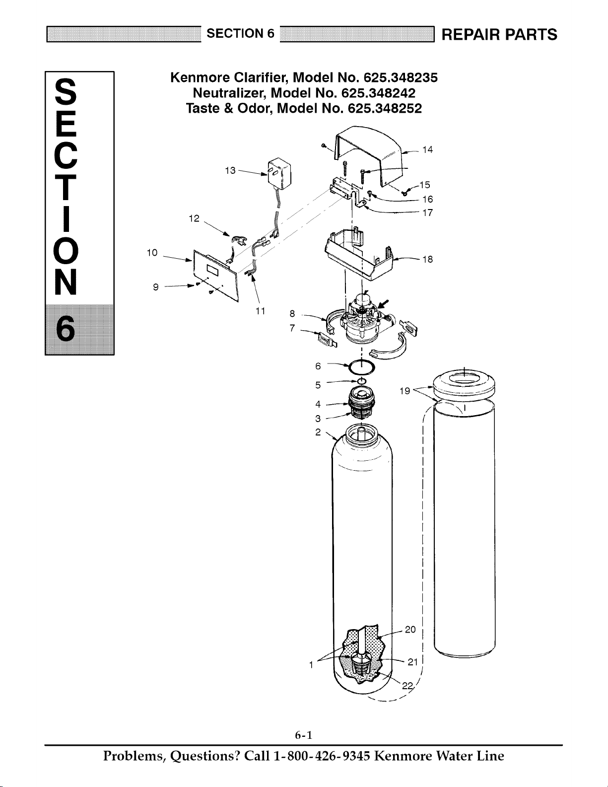
Kenmore Clarifier, Model No. 625.348235
Neutralizer, Model No. 625.348242
Taste & Odor, Model No. 625.348252
14
16
12 _ _ _ _ 17
7
4_ 19
1
6-1
Problems, Questions? Call 1-800-426-9345 Kenmore Water Line
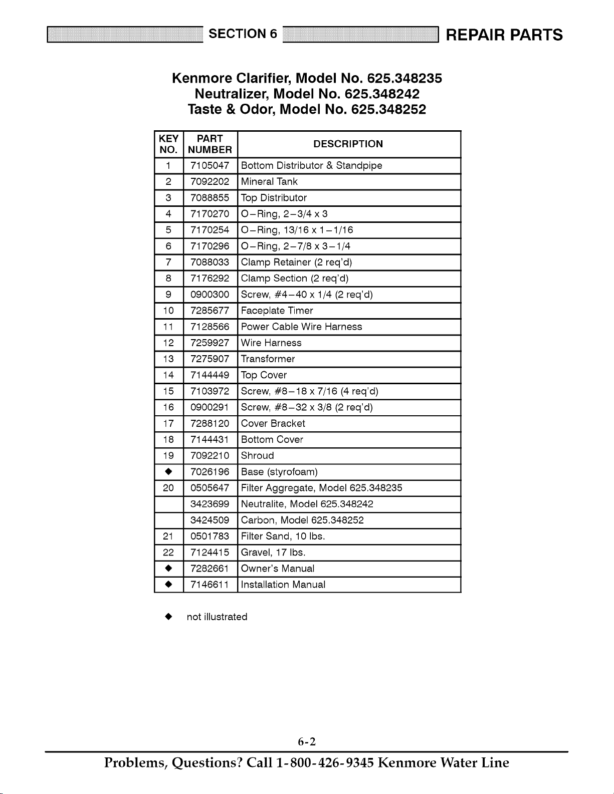
Kenmore Clarifier, Model No. 625.348235
Neutralizer, Model No. 625.348242
Taste & Odor, Model No. 625.348252
KEY PART
DESCRIPTION
NO. NUMBER
1 7105047 Bottom Distributor & Standpipe
2 7092202 Mineral Tank
3 7088855 Top Distributor
4 7170270 O-Ring, 2-3/4 x 3
5 7170254 O-Ring, 13/16x1-1/16
6 7170296 O-Ring, 2-7/8 x3-1/4
7 7088033 Clamp Retainer (2 req'd)
8 7176292 Clamp Section (2 req'd)
9 0900300 Screw, #4-40 x 1/4 (2 req'd)
10 7285677 Faceplate Timer
11 7128566 Power Cable Wire Harness
12 7259927 Wire Harness
13 7275907 Transformer
14 7144449 Top Cover
15 7103972 Screw, #8-18 x 7/16 (4 req'd)
16 0900291 Screw, #8-32 x 3/8 (2 req'd)
17 7288120 Cover Bracket
18 7144431 Bottom Cover
19 7092210 Shroud
_I, 7026196 Base (styrofoam)
20 0505647 Filter Aggregate, Model 625.348235
3423699 Neutralite, Model 625.348242
3424509 Carbon, Model 625.348252
21 0501783 Filter Sand, 10 Ibs.
22 7124415 Gravel, 17 Ibs.
_I, 7282661 Owner's Manual
_I, 7146611 Installation Manual
_I, not illustrated
6-2
Problems, Questions? Call 1-800-426-9345 Kenmore Water Line
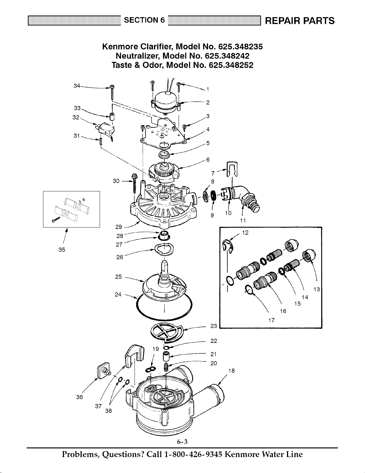
Kenmore Clarifier, Model No. 625.348235
Neutralizer, Model No. 625.348242
Taste & Odor, Model No. 625.348252
3O
2
4
5
8
10
18
11
12
16
17
14
15
36
37
38
6-3
Problems, Questions? Call 1-800-426-9345 Kenmore Water Line
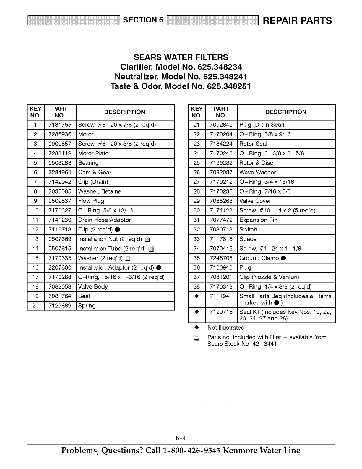
SEARS WATER FILTERS
Clarifier, Model No. 625.348234
Neutralizer, Model No. 625.348241
Taste & Odor, Model No. 625.348251
KEY PART
DESCRIPTION
NO. NO.
1 7131755 Screw, #6-20 x 7/8 (2 req'd)
2 7285936 Motor
3 0900857 Screw, #6-20 x 3/8 (2 req'd)
4 7288112 Motor Plate
5 0503288 Bearing
6 7284964 Cam & Gear
7 7142942 Clip (Drain)
8 7030585 Washer, Retainer
9 0509537 Flow Plug
10 7170327 O-Ring, 5/8 x 13/16
11 7141239 Drain Hose Adaptor
12 7116713 Clip (2req'd)•
13 0507369 Installation Nut (2 req'd)
14 0507615 Installation Tube (2 req'd)
15 7170335 Washer (2 req'd)
16 2207800 Installation Adaptor (2 req'd) •
17 7170288 O-Ring, 15/16 x 1-3/16 (2 req'd)
18 7082053 Valve Body
19 7081764 Seal
20 7129889 Spring
KEY PART
DESCRIPTION
NO. NO.
21 7092642 Plug (Drain Seal)
22 7170204 O-Ring, 3/8 x 9/16
23 7134224 Rotor Seal
24 7170246 O-Ring, 3-3/8 x 3-5/8
25 7199232 Rotor & Disc
26 7082087 Wave Washer
27 7170212 O-Ring, 3/4x 15/16
28 7170238 O-Ring, 7/16 x 5/8
29 7085263 Valve Cover
30 7174123 Screw, #10-14 x2 (5 req'd)
31 7077472 Expansion Pin
32 7030713 Switch
33 7117816 Spacer
34 7070412 Screw, #4-24x 1-1/8
35 7248706 Ground Clamp •
36 7100940 Plug
37 7081201 Clip (Nozzle & Venturi)
38 7170319 O-Ring, 1/4x3/8 (2 req'd)
_I, 7111941 Small Parts Bag (Includes all items
marked with • )
_I, 7129716 Seal Kit (Includes Key Nos. 19, 22,
23, 24, 27 and 28)
_I, Not Illustrated
Parts not included with filter - available from
Sears Stock No. 42-3441
6-4
Problems, Questions? Call 1-800-426-9345 Kenmore Water Line
Your Home
For repair-in your home-of all major brand appliances,
lawn and garden equipment, or heating and cooling systems,
no matter who made it, no ma_er who sold it!
For the replacement pa_s, accessories and
owner's manuals that you need to do-it-yourself.
For Sears professional installation of home appliances
and items like garage door openers and water heaters.
1-800-4-MY-HOME ®
Call anytime, day or night (U.S.A. and Canada)
www.sea_.co m _'_+sea rs+ca
Our Home
For repair of carry-in items like vacuums, lawn equipment,
and electronics, call or go on-line for the location of your nearest
Sears Pa_s & Repair Center.
1-800-488-1222
Call an_ime, day or night (U.SA only)
www.sea rs,com
To purchase a protection agreement (U.S.A.)
or maintenance agreement (Canada) on a product serviced by Sears:
1-800-827-6655 (U.S.A,) 1-800-361-6665 (Canada)
Para pedir servicio de reparaci6n
a domicilio, y para ordenar piezas:
1-888-SU-HOGAR SM
(I-888-784-6427)
Au Canada pour servi_ en fran£ais:
t -800-LE-FOYER Mc
(1-800-533-6937)
www, sears.
!iIiiii:!iiiiiiiii_i_iii_iii_iii_iii_iii_iii_iii_iii_iii_iii_iii_iii_iii_iii_iii_iii_iii_iii_iii_iii_iii_iii_iii_iii_iii_iii_iii_iii_iii_iii_iii_iii_iii_iii_iii_iii_iii_iii_iii_iii_ii_ii
IN
® Reg_tered TrademaA / Trademark / _,_Sewice Mark of Seam, Roebuck and Co.
® Marca Registrada l _ Marca de F_bdca/s_ Marc;ade Servicio de Sears, Roebuck and Co_
_c Maque de commerce I t_, Marque depos_e de Sea_, Roebuck and Co, @ Seam Roebuck and Co.