Loading ...
Loading ...
Loading ...
CULINARIAN SERIES
25
INSTALLATION INSTTRUCTIONS
WARNING! The third prong SHOULD
NOT, under
any circumstances, be cut
or removed!
GROUNDING METHOD
The rangetop is factory fitted with a power supply and
cord with a three
-
prong grounding plug. It must be
plugged into a matching grounding type receptacle
con -
nec t ed to a co r rect ly pol a rize d 1 20 Vol t
circuit. If
the circuit does not have a grounding type
receptacle, it is
the responsibility of the installer to
have the existing
receptacle changed to a properly
grounded and polarized
receptacle in accordance
with all applicable local codes
and ordinances. The
receptacle replacement shall be in
accordance with
the national Electrical Code.
CAUTION! Disconnect the electrical supply
cord
from the wall outlet before
servicing
the rangetop.
Follow all governing codes and
ordinances when
grounding. In the absence of
codes follow the
National Electrical
Codes
ANSI / NFPA No. 70
(current issue).
30" RangeTop
–
120V 15 Amps. Max.
36" RangeTop
–
120V 15Amps. Max.
48" RangeTop
–
120V 15 Amps. Max.
60" RangeTop
–
120V 15 Amps. Max
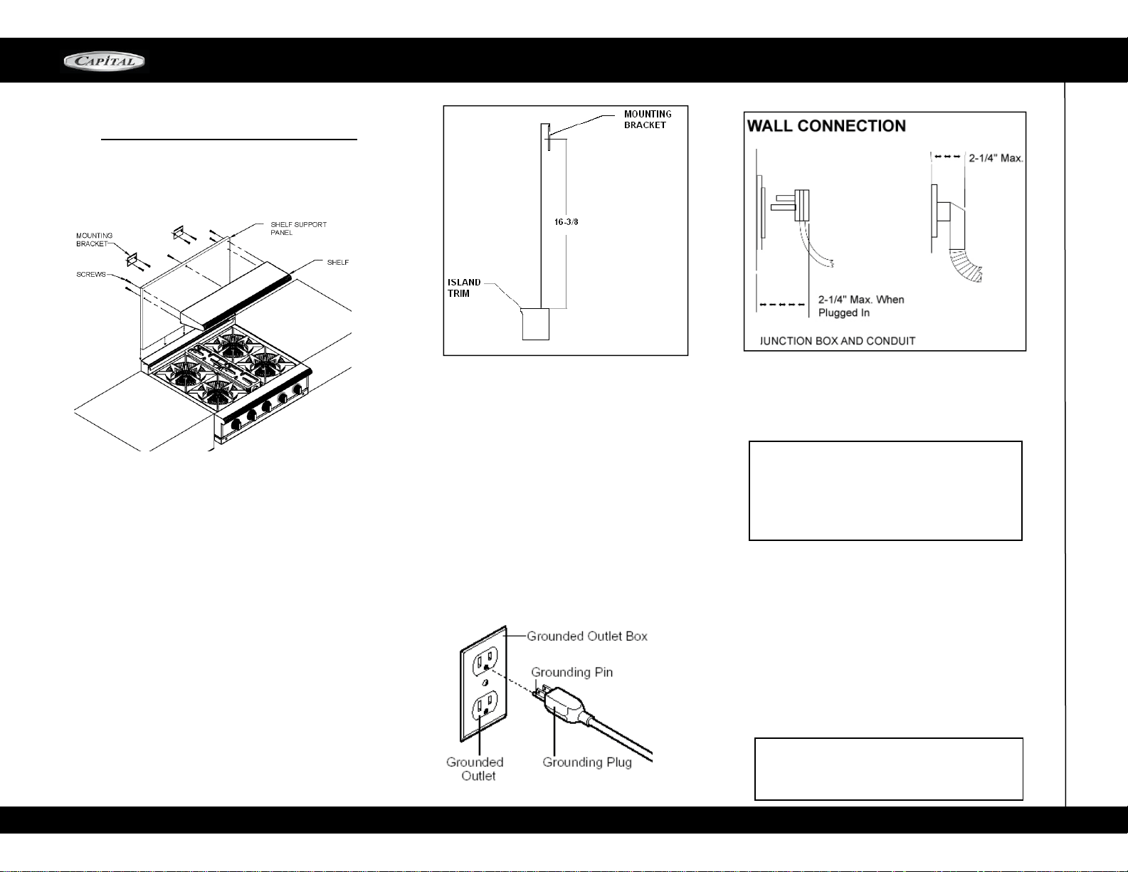
ELECTRICAL SUPPLY, ALL RANGES
In stallati on of All Cu linar ian rang eto ps mus t
be
planned so that the rough
-
in of the junction
box
for the receptacle or conduit connection allows for
maximum clearance to the rear of the unit.
This is especially critical if the junction box in the
wall is directly behind the junction box of the
unit when the unit is installed. To minimize binding
when the unit is connected to the receptacle or
junction box, orient the receptacle or conduit
connector, and slide back into position.
POWER REQUIREMENTS:
120VAC, 60 HZ single phase
3.
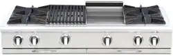
Attach the shelf to the shelf support panels
with supplied screws.
4.
Slide shelf into position and over brackets.
NOTE
WALL MOUNT BACKGUARD INSTALLATION
2.
Secure both brackets to the wall
using the
screws included
1.
First measure from top of back trim to 16 3/8"
to what will be the center of the mounting
brackets. (see Fig 1)
Loading ...
Loading ...
Loading ...