Loading ...
Loading ...
Loading ...
18 19
Cut Out Dimensions for Built-in H / HF Series
Cut Out Dimensions for Built-in HP / XLP Series
Overall Dimensions for P Series Freestanding
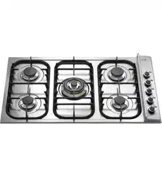
BUILT-IN INSTALLATION
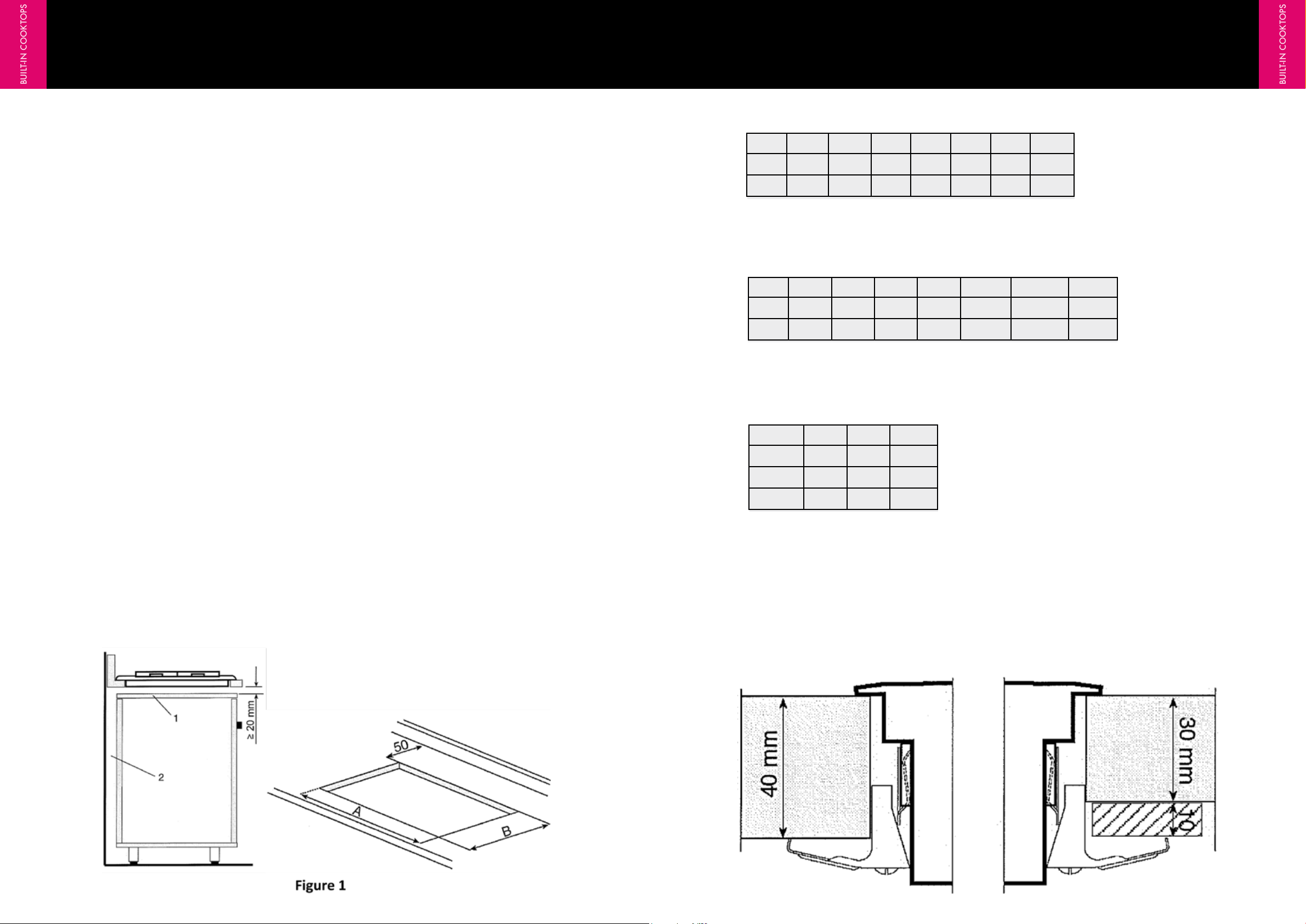
To avoid liquid infiltrations under the working tops, it is necessary to apply a gasket which is supplied with
the top. The fixing to the furniture is carried out with clamps assembled on the appliance as per Figure 2.
For Freestanding cooking hob models (P665, P965, P1265) must be installed with the top of the hob level
with the bench and must support a minimum weight of 100 kg.
Mod P665 P965 P1265
A
600 900 1200
B
650 650 650
Height
85 85 85
GENERAL
1. The requirements of local Gas and Electrical authorities must be adhered to, Consult AG 601 / ASNZS
5601 and SAA Wiring Rules as appropriate
2. Location of gas inlet- At rear of the cook top located on the right, left or centre depending on the
model (Refer to model specifications)
3. Electrical connection - 240mm C/L from RH side (as viewed from front) 40mm C/L from rear Connection
is by means of flexible cord and plug to 10 amp GPO
4. Overall dimensions of hotplate - Refer to dimensions chart in following pages
5. Eurolinx Pty Ltd and their appointed agents decline any responsibilities in the case of installation not
according to these instructions.
HOTPLATE CLEARANCES
The hotplate is to be installed as detailed below When the hotplate is installed abutting a side or rear wall,
the wall must be of non-combustible material, eg ceramic tiles.
The following minimum clearances to combustible materials must be observed: Minimum clearance from
hotplate edge to side wall must be 200mm.
Minimum clearance from hotplate edge to rear wall must be 200mm
Minimum clearance from hotplate to cupboard above hob burners must be 600mm
Range hoods and overhead exhaust fans must be installed according to the manufacturers’ instructions
but in no case shall clearance from hob burners be less than 600mm for the range hood and 750mm for
the overhead exhaust fan.
It is recommended that the adjacent kitchen surfaces should be capable of withstanding
temperatures of 100°C
FITTING THE COOKING HOB ONTO THE BASE UNIT WITH DOOR
The unit must be made in such a way that the flames are not blown out if the doors are opened
or closed rapidly. The bottom of the cooking hob must not be subject to depression or pressure
when the doors are opened or closed. We advise working as shown in figure A). The panel
under the hob must be easy to remove for maintenance purposes.
Mod H30 H360 H60 H70 H38 H39 HF40
A
270 555 555 555 755 835 360
B
475 475 475 475 475 475 490
Mod HP45 HP65 HP95 HP75 HP125 HP1230 XLP90
A
380 570 850 680 1130 1120 875
B
481 485 485 490 480 300 570
Figure 2
COOKTOP INSTALLATION INSTRUCTIONS
BUILT-IN COOKTOPS
BUILT-IN COOKTOPS
ILVE COOKTOPS OPERATING MANUAL ILVE COOKTOPS OPERATING MANUAL
Loading ...
Loading ...
Loading ...