Loading ...
Loading ...
Loading ...
OPERATING THE COUPLER
This model is equipped with a coupler
which enables optional attachments to
be installed. The optional attach-
ments are:
Edger ................. 358.792400
Cultivator .............. 358.792410
Blower ................ 358.792420
Brushcutter ............ 358.792430
_.WARNING: Always stop unit
and disconnect spark plug before re-
moving or installing attachments.
REMOVING TRIMMER ATTACH-
MENT (OR OTHER OPTIONAL AT-
TACHMENTS)
CAUTION: When removing or instal-
ling attachments, place tile unit on a
flat surface for stability.
1. Loosen the coupler by turning the
knob counterclockwise.
upper Tube
Coupler
Lower \
Attachment
TIGHTEN Knob
2. Press and hold the locking/release
button.
Locking/Release
Button
Upper Tube
Lower Attachment
3. While securely holding the engine
and upper tube, pull the attach-
ment straight out of the coupler.
INSTALLING OPTIONAL ATTACH-
MENTS
1. Remove the tube cap from the at-
tachment (if present).
2. Position locking/release button of
attachment into guide recess of
coupler.
3. Push the attachment into the cou-
pler until the locking/release button
snaps into the primary hole.
4. Before using the unit, tighten the
knob securely by turning clock-
wise.
_WARNING: Make sure the lock-
ing/release button is locked in the pri-
mary hole and the knob is securely
tightened before operating the unit.
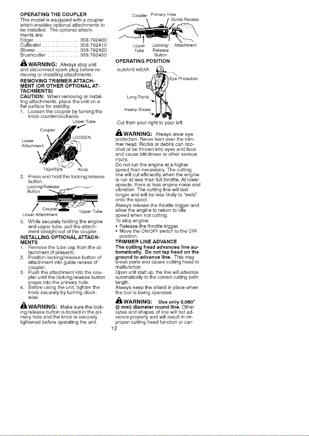
Coupler Primary Hole
Guide Recess
Upper Locking/
Tube Release
Button
OPERATING POSITION
Attachment
ALWAYS WEAR:
Protection
Long Pants
Heavy Shoes
Cut from your right to your left.
_tWARNING: Always wear eye
protection. Never lean over the trim-
mer head. Rocks or debris can rico-
chet or be thrown into eyes and face
and cause blindness or other serious
injury.
Do not run the engine at a higher
speed than necessary. The cutting
line will cut efficiently when the engine
is run at less than full throttle. At lower
speeds, there is less engine noise and
vibration. The cutting line will last
longer and will be less likely to "weld"
onto the spool.
Always release the throttle trigger and
allow the engine to return to idle
speed when not cutting.
To stop engine:
• Release the throttle trigger.
• Move the ON/OFF switch to the OFF
position.
TRIMMER LINE ADVANCE
The cutting head advances line au-
tomatically. Do not tap head on the
ground to advance line. This may
break parts and cause cutting head to
malfunction.
Upon unit start up, the line will advance
automatically to the correct cutting path
length.
Always keep the shield in place when
the tool is being operated.
WARNING: Use only 0.080"
(2 mm) diameter round line. Other
sizes and shapes of line will not ad-
vance properly and will result in im-
proper cutting head function or can
12
Loading ...
Loading ...
Loading ...