Loading ...
Loading ...
Loading ...
18
2
OPERATIONS TO BE PERFORMED WHEN SUBSTITUTING THE
INJECTORS
• Removethepansupports,theburnercapsandtheamespreaders.
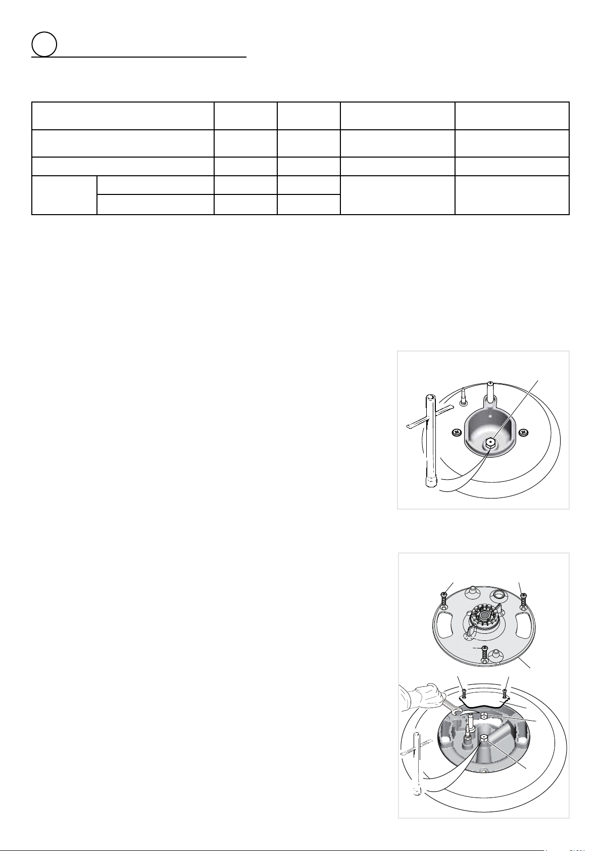
• Dualburneronly(g.2.12):Unscrewtheno.3xingscrews“A”andremovetheinner
crownamespreader“B”;thenunscrewtheno.2xingscrews“C”andremovethe
coverplate“D”.
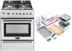
• Usingawrenchsubstitutethenozzleinjectors“J
1
”,“J
2
”and“J
3
”(gs.2.11,2.12)with
thosemostsuitableforthekindofgasforwhichitistobeused.
• Dualburneronly(g.2.12):
Ret
thecoverplate“D”andscrewtheno.2xingscrews
“C”;thenrettheinnercrownamespreader“B”andscrewtheno.3xingscrews
“A”
• Rettheamespreaders,theburnercapsandthepansupports.
The burner are conceived in such a way so as not to require the regulation of the
primary air.
SECOND ORIFICE
DEUXIEME ORIFICE
A
A
A
B
C
C
D
J
2
J
3
Fig. 2.12
J
1
Fig. 2.11
SEMI-RAPID BURNER
DUAL BURNER
INJECTORS TABLE
NOMINAL
POWER
REDUCED
POWER
LP/PROPANE
11”W.C.P.
NATURAL GAS
4”W.C.P.
BURNERS BTU/hr BTU/hr
Øinjector
[1/100mm]
Øinjector
[1/100mm]
Semirapid(SR) 8000 1500 85 139
Dual(D)
Innercrown 2100 1000
42(*)
115(#)
70(*)
200(#)
Inner&outercrown 17000 6500
(*) innercrown(“J
2
”ingure2.12)
(#) outercrown(“J
3
”ingure2.12)
Loading ...
Loading ...
Loading ...