Loading ...
Loading ...
Loading ...
page 7
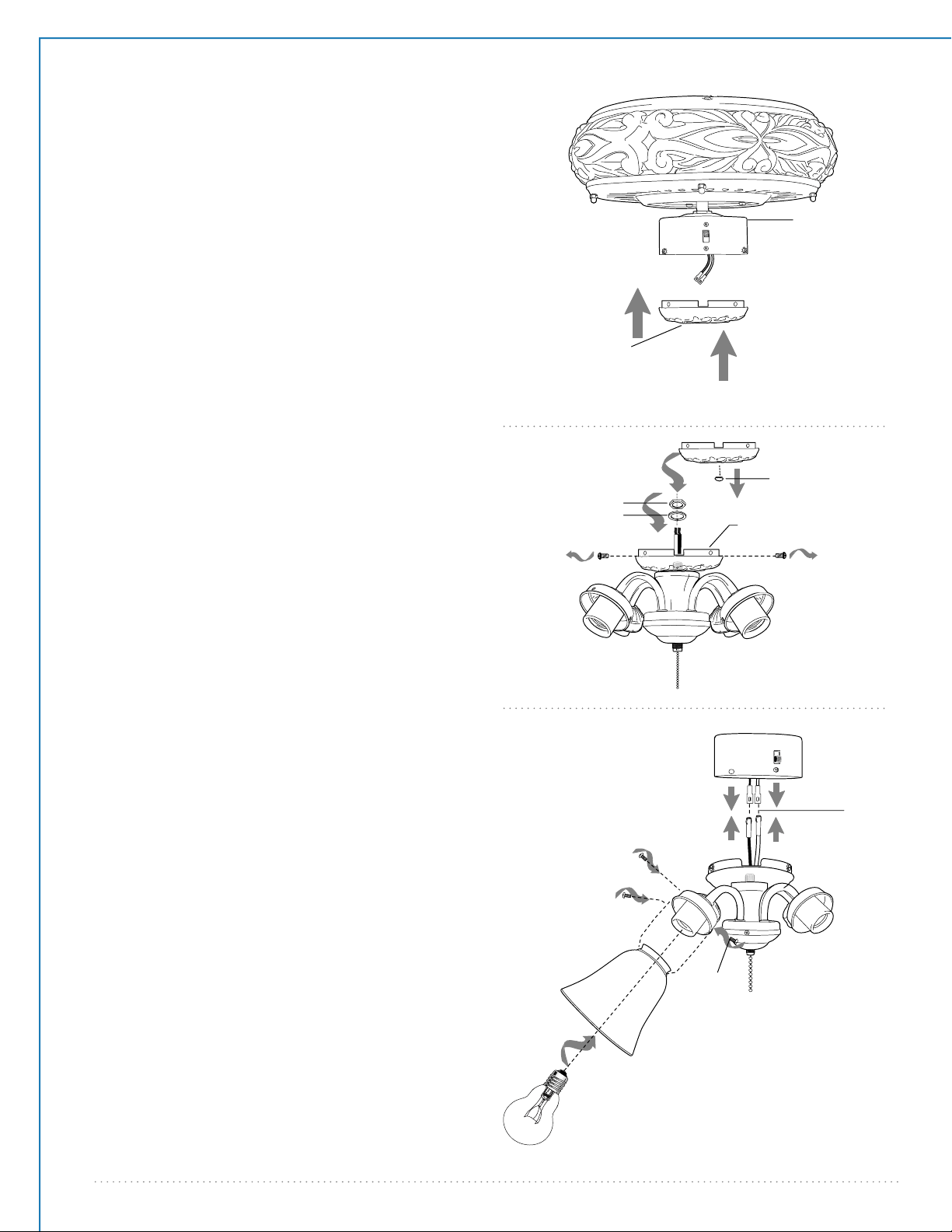
9. Light Kit Assembly (Optional).
Remove 3 screws from switch housing cap.
If you wish to use your fan WITHOUT the light
kit, align holes in switch housing cap with holes in
switch housing. (Note: Gap on edge of switch
housing cap must align with reverse switch in
switch housing for the proper fit.) Secure switch
housing cap with 3 screws that were previously
removed. Please proceed to Section 10 on the
following page to complete installation without
light kit. [Refer to diagram 1.]
If you wish to use your fan WITH the light kit,
locate BLACK (or BLUE) and WHITE wires in
switch housing labeled FOR LIGHT. Remove and
discard plastic that holds these 2 wires together.
Remove hex nut and lock washer from threaded
rod on light kit fitter. Punch center cap out of
switch housing cap with a screwdriver. Feed
wires from light kit fitter through center hole in
switch housing cap, and then screw switch
housing cap onto threaded rod followed by the
lock washer and hex nut. Tighten hex nut over
lock washer for a secure fit. [Refer to diagram 2.]
switch housing
cap
Connect WHITE wire from switch housing to
WHITE wire from light kit fitter. Connect BLACK
(or BLUE) wire from switch housing to BLACK
wire from light kit fitter. Be sure that molex
connections snap together securely.
Align holes in light kit fitter with holes in switch
housing. Attach light kit fitter to switch housing
with 3 screws that were removed. Secure all 3
screws with Phillips screwdriver.
Attach 4 glass shades using thumbscrews
provided in one of the hardware packs. Do NOT
overtighten thumbscrews as glass may crack or
break.
Install 4 candelabra base 40 watt max. bulbs
(included).
Important: When you need to replace bulbs,
please allow bulb(s) and glass shade to cool
down before touching them.
[Refer to diagram 3.]
white
white
black
black
(or blue)
glass shade
thumb-
screws
bulb
switch housing
light kit
fitter
thumb-
screw
molex
connections
switch
housing
motor housing
switch housing cap
hex nut
lock washer
light kit fitter
switch housing cap
center cap
diagram 1
diagram 2
diagram 3
Loading ...
Loading ...
Loading ...