Loading ...
Loading ...
3
ENGLISH
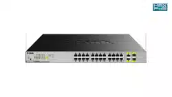
Rear Panel Connectors
1 2 43
Figure 3
# Item Description
1
Kensington
Lock Input
This is used to attach a physical Kensington
security lock.
2 Switch GND This is used to connect the switch to ground.
3
Power Cord
Retainer Slot
This is used for securing the power cord
retainer to the switch.
4
Power Adapter
Input
This is used to connect the power cable to the
switch.
Table 3
Hardware Installation
Before You Begin
Observe the following precautions to help prevent
shutdowns, equipment failures, and personal injury:
• Install the DGS-1026MP in a cool and dry
place. Refer to the technical specications in
the user manual for the acceptable operating
temperature and humidity ranges.
• Install the switch in a site free from strong
electromagnetic sources, vibration, dust, and
direct sunlight.
• Leave at least 10 cm of space at the left and right-
hand side of the switch for ventilation.
• Visually inspect the power connector and make
sure that it is fully secured to the power cord.
• Do not stack any devices on top of the switch.
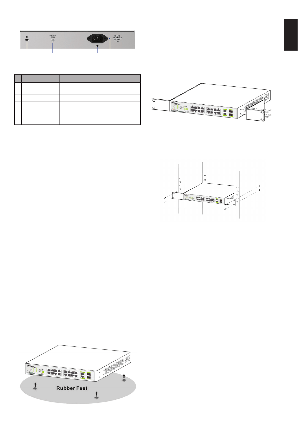
Using the Switch on a Flat Surface
The DGS-1026MP comes with a set of adhesive
rubber feet which allow the switch to be placed on
a at surface such as a desk or table, without risk of
damaging it. To attach the rubber feet, simply place
one in each corner of the bottom panel of the switch.
Figure 4
Mounting the Switch in a Rack
The DGS-1026MP can be mounted into a standard
19” server rack. The following instructions will explain
how to install the switch into a rack:
1. Attach the included mounting brackets to each
side of the switch’s chassis and secure them to
the device using the provided screws.
Figure 5
2. Use the screws that were provided with the rack
to install the switch in the rack.
Figure 6
Grounding the Switch
This section will provide step-by-step instructions
on how to connect the switch to ground. This step
must be completed before powering on the switch.
Required tools and equipment for grounding
• Grounding screw (included) and one M4x6
(metric) pan-head screw (not included).
• Grounding cable (not included). The grounding
cable should be sized according to local and
national installation requirements. Depending
on the power supply and system, a 12 to 6 AWG
copper conductor is required for installation.
Commercially available 6 AWG wire is
recommended. The length of the cable depends
on the proximity of the switch to proper
grounding facilities.
• A screwdriver (not included).
Loading ...
Loading ...
Loading ...