Loading ...
Loading ...
Loading ...

17
HOOD VERSION
INSTALLATION
For the installation of this product it is necessary
to create a plasterboard lowering, keeping at le-
ast 220mm distance between the same and the
solid ceiling.
The material supplied with the product allows it
to be installed on lowerings ranging from 220mm
(g. 2) to 300mm (g. 3) of distance between the
plasterboard and the solid ceiling.
It is necessary to make a circular opening in the
plasterboard, with a diameter equal to: 510mm
(g. 4)
Using a level and a pencil, bring the four ends of
the holes created in the plasterboard directly into
the solid ceiling, see g. 5, then draw perpendi-
cular lines as shown in g. 6, in order to nd the
center of the hole.
Position the drilling template supplied, aligning
the centre of the template with the centre of the
axes previously drawn (g. 7). Using a pencil, tra-
ce the three holes to be made in the solid ceiling.
Before tracing the holes you can rotate the
drilling template in order to orient the air out-
let of the fan in the desired direction. The po-
sition of the air outlet of the fan is indicated in the
drilling template.
Perform the three holes in the solid ceiling using
a helical tip with a diameter of 8mm.
Insert the metric inserts supplied into the holes
made.
Insert the threaded bars into the metric inserts
previously installed.
Screw the threaded bars using two nuts, as
shown in g. 8, act in the nut below to screw the
threaded bar.
Insert an additional nut, a metal washer and a
plastic locking washer as shown in gure 9. For
correct installation, position the metal washer
200mm high from the bottom surface of the
plasterboard, see gure 10.
Remove the product from its packaging and place
it on a suitable surface: we suggest using a soft
material, such as a sponge or a cloth.
Open the panel as shown in Fig. 1 and described
in the previous paragraph, remove the grease lter
using the handle.
Using a suitable tool, remove the eight screws
securing the outer frame and then remove it as
shown in Fig. 11.
Also disconnect the at cable and the electrical ca-
ble of the reset button.
Install the upper part of the product in the plaster-
board niche, the three slots must coincide with the
threaded rods previously installed, as shown in g.
12.
Bring the product to a stop with the washers pre-
viously positioned.
Secure the product with three washers and three
nuts supplied. (g. 13)
Connect the air outlet duct and the power supply.
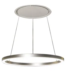
Remove the LED ceiling light from its packaging
and run the cables through the three holes in the
frame (g. 14).
Adjust the desired height of the LED ceiling light to
the oor using the cable clamp as shown in g. 15.
Move the frame closer to the plasterboard niche,
then restore the previously removed electrical con-
nections and make the electrical connection of the
LED ceiling light, taking care not to confuse the
positive, negative and ground polarities indicated
by the labels in the electrical cables.
Lock the niche to the product previously xed with
the eight screws previously removed, g. 16.
Restore the grease lter and the metal panel xed
with special magnets.
Loading ...
Loading ...
Loading ...