
LA CUCINA 36” - 30 “ models
Installation, use and care manual


Congratulations and welcome to the SUPERIORE’s world. We hope you will enjoy and
appreciate the care and attention we put into every detail of your new, state-of-the-art
range.
Your SUPERIORE range is designed to offer years of reliable service. This Use and Care
Manual will provide the information you need to become familiar with your product’s care
and operation.
Your complete satisfaction is our ultimate goal. If you have any questions or comments
about this product, please contact the dealer from whom you purchased it, contact our
Customer Care Service or visit our SUPERIORE channel on Youtube.
We appreciate your choice of a SUPERIORE range and hope that you will choose again
our products.
For more information about the complete and growing selection of SUPERIORE products,
contact your dealer or visit us online at SUPERIORE.US
Antonio Di Tommaso
CEO
Congratulations

WARNING:
If the information in this manual is not followed exactly, a fire or
explosion may result causing property damage, personal injury or death.
• Do not store or use gasoline or other ammable vapors and liquids in the vicinity
of this or any other appliance.
• WHAT TO DO IF YOU SMELL GAS:
– Do not try to light any appliance.
– Do not touch any electrical switch;
– Do not use any phone in your building.
– Immediately call your gas supplier from a neighbor’s phone. Follow the gas
supplier’s instructions.
– If you cannot reach your gas supplier, call the re department.
• Installation and service must be performed by a qualied installer, service agency
or the gas supplier.

CONTENTS
Warnings
Dimensions
Specications Technical data, 36” models
Specications Technical data, 30” models
Clearance Dimensions 36’’/30’’
Electrical & Gas Requirements
Gas Requirements
General Information
Leg Installation/Adjustments/Alignments
Anit-tip Device Installation
Installation/ Door Removal
Connecting Gas & Electrical
Performance Checklist
Before Using the Range
Range Features
Surface Operation
Burners Operation
Oven Functions and Setting
Oven Features
Using the Oven
Baking
Convection Bake
Defrost
Broiling
Care and cleaning
Cleaning and Maintenance
Replacing Oven Light
Door Remova
Thanksgiven dinner
Service Information
Troubleshooting
Warranty U.S.A. & CANADA
Electric diagrams
6
12
16
17
20
21
27
28
29
30
31
32
33
34
38
39
40
41
42
43
46
47
48
50
51
53
54
55
58
59
60
61
18
6
|
Warnings
Getting Started Warning and Important
Safety Instructions appearing in this
manual are not meant to cover all possible
conditions and situations that may occur.
Common sense, caution, and care must be
exercised when installing, maintaining or
operating the appliance.
ALWAYS contact the manufacturer about
problems or conditions you do not
understand.
Recognize Safety Symbols, Words, Labels
DANGER
Hazards or unsafe practices which WILL
result in severe personal injury or death
WARNING
Hazards or unsafe practices which COULD
result in death or severe personal injury
CAUTION
Hazards or unsafe practices which COULD
result in minor personal injury.
All safety messages will identify the hazard, tell
you how to reduce the chance of injury, and tell
you what can happen if the instructions are not
followed.
Read and follow all instructions before using
this appliance to prevent the potential risk of
re, electric shock, personal injury or damage to
the appliance as a result of improper usage of
the appliance. Use appliance only for its intended
purpose as described in this manual.
To ensure proper and safe operation:
Appliance must be properly installed and grounded
by a qualied technician. DO NOT attempt to
adjust, repair, service, or replace any part of your
appliance unless it is specically recommended in
this manual. All other servicing should be referred
to a qualied servicer. Have the installer show you
the location of the gas shutoff valve and how to
shut it off in an emergency.
A certied technician is required for any
adjustments or conversions to Natural or LP gas.
KEEP THESE INSTRUCTIONS FOR
FUTURE REFERENCE
DANGER
If the information in this manual is not
followed exactly, a fire or explosion may
result causing property damage, personal
injury or death.
WHAT TO DO IF YOU SMELL GAS:
• DO NOT try to light any appliance.
• DO NOT touch any electrical switch.
• DO NOT use any phone in your building.
• Immediately call your gas supplier from a
neighbor’s phone. Follow the gas supplier’s
instructions.
• If you cannot reach your gas supplier, call the re
department.
Installation and service must be performed
by a qualified installer, service agency or the
gas supplier.
WARNING
TIPPING HAZARD
To reduce the risk of the appliance
tipping, it must be secured by a
properly installed anti-tip bracket(s).
To make sure the bracket has been
installed properly, look behind the range with a
ashlight to verify proper installation engaged in
the rear top left corner of the range.
• THIS RANGE CAN TIP
• INJURIES TO PERSONS CAN RESULT
• INSTALL ANTI-TIP DEVICE PACKED
WITH RANGE
• SEE INSTALLATION INSTRUCTIONS
DANGER
DO NOT use commercial oven cleaners inside
the oven. Use of these cleaners can produce
hazardous fumes or can damage the porcelain
nishes.
DANGER
To avoid risk of property damage,
personal injury or death; follow
information in this manual exactly to
prevent a re or explosion. DO NOT
store or use gasoline or other ammable vapors
and liquids in the vicinity of this or any appliance.

|
7
Warnings
To Prevent Fire or Smoke Damage
• Be sure all packing materials are removed from
the appliance before operating it.
• Keep area around appliance clear and free
from combustible materials, gasoline, and other
ammable vapors and materials.
• If the appliance is installed near a window, proper
precautions should be taken to prevent curtains
from blowing over burners.
NEVER leave any items on the top. The hot air
from the vent may ignite ammable items and may
increase pressure in closed containers which may
cause them to burst.
• Many aerosol-type spray cans are EXPLOSIVE
when exposed to heat and may be highly
ammable. Avoid their use or storage near an
appliance.
• Many plastics are vulnerable to heat. Keep plastics
away from parts of the appliance that may become
warm or hot. DO NOT leave plastic items on
the rangetop as they may melt or soften if left too
close to the vent or alighted surface burner.
• Combustible items (paper, plastic, etc.) may ignite
and metallic items may become hot and cause
burns. DO NOT pour spirits over hot foods.
DO NOT leave oven unsupervised when drying
herbs, breads, mushrooms, etc; re hazard.
In Case of Fire
Turn off appliance and ventilating hood to avoid
spreading the ame. Extinguish ame then turn on
hood to remove smoke and odor.
• Worktop: Smother re or ame in a pan with a
lid or cookie sheet.
• NEVER pick up or move a aming pan.
• Oven: Smother re or ame by closing the
oven door. DO NOT use water on grease res.
Use baking soda, a dry chemical or foam-type
extinguisher to smother re or ame.
• Grease is ammable and should be handled
carefully. DO NOT use water on grease res.
Flaming grease can be extinguished with baking
soda or, if available, a multipurpose dry chemical
or foam type extinguisher. Let fat cool before
attempting to handle it. DO NOT allow grease
to collect around the oven or in vents. Wipe up
spillovers immediately.
Child Safety
• NEVER leave children alone or unsupervised
near the appliance when it is in use or is still hot.
• NEVER allow children to sit or stand on any
part of the appliance as they could be injured or
burned.
• DO NOT store items of interest to children over
the unit. Children climbing to reach items could
be seriously injured.
• Children must be taught that the appliance and
utensils in it can be hot. Let hot utensils cool in a
safe place, out of reach of small children. Children
should be taught that an appliance is not a toy.
Children should not be allowed to play with
controls or other parts of the appliance.
Cooking Safety
• To eliminate the hazard of reaching over hot
surface burners, cabinet storage should not
be provided directly above a unit. If storage is
provided,it should be limited to items which are
used in frequently and which are safely stored
in an area subjected to heat from an appliance.
Temperatures may be unsafe for some items, such
as volatile liquids, cleaners or aerosol sprays.
• ALWAYS place a pan on a surface burner
before turning it on. Be sure you know which
knob controls which surface burner. Make sure
the correct burner is turned on and that the
burner has ignited. When cooking is completed,
turn burner off before removing pan to prevent
exposure to burner ame.
• ALWAYS adjust surface burner ame so that
it does not extend beyond the bottom edge of
the pan. An excessive ame is hazardous, wastes
energy and may damage the appliance, pan or
cabinets above the appliance. This is based on
safety considerations.
• NEVER leave a surface cooking operation
unattended especially when using high heat
setting or when deep fat frying. Boilovers cause
smoking and greasy spillovers may ignite. Clean
up greasy spills as soon as possible.
DO NOT use high heat for extended cooking
operations.
• DO NOT heat unopened food containers,
build up of pressure may cause the container to
explode and result in injury.
• Use dry, sturdy pot-holders. Damp pot-holders
may cause burns from steam. Dishtowels or other
substitutes should NEVER be used as potholders
because they can trail across hot surface burners
and ignite or get caught on appliance parts.
• ALWAYS let quantities of hot fat used for deep
fat frying cool before attempting to move or
handle.
• DO NOT let cooking grease or other ammable
materials accumulate in or near the appliance,
hood or vent fan. Clean hood frequently to
prevent grease from accumulating on hood or

8
|
Warnings
lter. When aming foods under the hood, turn
the fan off.
• NEVER wear garments made of ammable
material or loose tting or long-sleeved apparel
while cooking. Clothing may ignite or catch utensil
handles. DO NOT drape towels or materials on
oven door handles.These items could ignite and
cause burns.
• ALWAY Splace oven racks in the desired
positions while oven is cool. Slide oven rack out
to add or remove food, using dry, sturdy pot-
holders. ALWAYS avoid reaching into the oven
to add or remove food. If a rack must be moved
while hot, use a dry pot-holder.
• ALWAYS turn the oven off at the end of cooking.
• Use care when opening the oven door. Let hot air
or steam escape before moving or replacing food.
• NEVER use aluminum foil to cover oven racks or
oven bottom. This could result in risk of electric
shock, re, or damage to the appliance. Use foil
only as directed in this guide.
• PREPARED FOOD WARNING: Follow food
manufacturer’s instructions.
If a plastic frozen food container and/or its cover
distorts, warps, or is other wise damaged during
cooking, immediately discard the food and its
container. The food could be contaminated.
• If you are “aming” liquor or other spirits under
an exhaust, TURN THE FAN OFF. The draft
could cause the ames to spread out of control.
• Once the unit has been installed as outlined in
the Installation Instructions, it is important that
the fresh air supply is not obstructed.The use of
a gas cooking appliance results in the production
of heat and moisture in the room in which
it is installed. Ensure that the kitchen is well-
ventilated. Keep natural venting holes open or
install a mechanical ventilation device. Prolonged
or intensive use of the appliance may call for
additional (such as opening a window) or more
effective ventilation (such as increasing the level
of a mechanical ventilation if present).
Utensil Safety
• Use pans with at bottoms and handles that are
easily grasped and stay cool. Avoid using unstable,
warped, easily tipped or loose-handled pans. Also
avoid using pans, especially small pans, with heavy
handles as they could be unstable and easily tip.
Pans that are heavy to move when lled with food
may also be hazardous.
• Be sure utensil is large enough to properly
contain food and avoid boilovers. Pan size is
particularly important in deep fat frying. Be sure
pan will accommodate the volume of food that is
to be added as well as the bubble action of fat.
• To minimize burns, ignition of ammable materials
and spillage due to unintentional contact with the
utensil, DO NOT extend handles over adjacent
surface burners. A LWAY Sturn pan handles
toward the side or back of the appliance, not
out into the room where they are easily hit or
reached by small children.
• NEVER let a pan boil dry as this could damage
the utensil and the appliance.
• Follow the manufacturer’s directions when using
oven cooking bags.
• Only certain types of glass, glass/ceramic, ceramic
or glazed utensils are suitable for rangetop
surface or oven usage without breaking due
to the sudden change in temperature. Follow
manufacturer’s instructions when using glass.
• This appliance has been tested for safe
performance using conventional cookware. DO
NOT use any devices or accessories that are not
specically recommended in this guide. DO NOT
use eyelid covers for the surface units, stovetop
grills, or add-on oven convection systems. The use
of devices or accessories that are not expressly
recommended in this manual can create serious
safety hazards, result in performance problems,
and reduce the life of the components of the
appliance.
• The ame of the burner should be adjusted to
just cover the bottom of the pan or pot. Excessive
burner setting may cause scorching of adjacent
counter-top surfaces, as well as the outside of the
utensil. This is based on safety considerations.
Heating Elements
• NEVER touch oven bake and broil burner areas
or interior surfaces of oven.
• Bake and broil burners may be hot even though
they are dark in color. Areas near burners and
interior surfaces of an oven may become hot
enough to cause burns.
• During and after use, DO NOT touch or let
clothing or other ammable materials contact
heating elements, areas near elements, or interior
surfaces of oven until they have had sufcient time
to cool. Other surfaces of the oven may become
hot enough to cause burns, such as the oven vent
opening, the surface near the vent opening, and
the oven door window.
Cleaning Safety
• Turn off all controls and wait for appliance parts
to cool before touching or cleaning them. DO
|
9
Warnings
NOT touch the burner grates or surrounding
areas until they have had sufcient time to cool.
• Clean appliance with caution. Use care to avoid
steam burns if a wet sponge or cloth is used to
wipe spills on a hot surface. Some cleaners can
produce noxious fumes if applied to a hot surface.
• No commercial oven cleaner or oven liner
protective coating such as aluminum foil should be
used in or around any part of the oven. Improper
oven liners may result in a risk of electric shock
or re. Keep oven free from grease buildup.
WARNING
NEVER use appliance as a space heater to heat or
warm a room to prevent potential hazard to the
user and damage to the appliance. Also, DO NOT
use the range top or oven as a storage area for food
or cooking utensils.
About Your Appliance
• For proper oven performance and
operation, DO NOT block or obstruct the
oven vent duct located in the backguard/
island trim.
• Avoid touching oven vent area while oven is on
and for several minutes after oven is turned off.
When the oven is in use, the vent and surrounding
area become hot enough to cause burns. After
oven is turned off, DO NOT touch the oven vent
or surrounding areas until they have had sufcient
time to cool.
• Other potentially hot surfaces include rangetop,
areas facing the rangetop, oven vent, surfaces near
the vent opening, oven door, areas around the
oven door and oven window.
• The misuse of oven doors (e.g. stepping, sitting, or
leaning on them) can result in potential hazards
and/or injuries.
Power Failure
If power failure occurs, the electric igniters will not
work. No attempt should be made to operate the
appliance during a power failure. Make sure the
ovencontrol is in the “OFF” position.
Momentary power failure can occur unnoticed. The
range is affected only when the power is interrupted.
When it comes back on, the range will function
properly without any adjustments. A “brown-out”
may or may not affect range operation, depending
on how severe the power loss is.
WARNING
ELECTRICAL SHOCK HAZARD
DO NOT touch a hot oven light
bulb with a damp cloth as the bulb
could break. Should the bulb break,
disconnect power to the appliance
before removing bulb to avoid electrical
shock.
WARNING
NEVER cover any slots, holes or passages in the
oven bottom or cover an entire rack with materials
such as aluminum foil. Doing so blocks air ow
through the oven and may cause carbon monoxide
poisoning. Aluminum foil linings may also trap heat,
causing a re hazard.
WARNING
ELECTRICAL SHOCK HAZARD
Disconnect the electric power at the
main fuse or circuit breaker before
replacing bulb.
WARNING
BURN OR ELECTRICAL SHOCK
HAZARD
Make sure all controls are OFF and oven
is COOL before cleaning. Failure to do
so can result in burns or electrical shock.
CAUTION
To avoid sickness and food waste, DO NOT allow
defrosted food to remain in the oven for more than
two hours.
NOTICE
DO NOT turn the Temperature Control on
during defrosting. Turning the convection fan on will
accelerate the natural defrosting of the food without
the heat.
10
|
CAUTION
BURN HAZARD
The oven door, especially the glass, can
get hot. Danger of burning: DO NOT
touch the glass!
CAUTION
You must carefully check the food during the
dehydration process to ensure that it does not catch
re.
CAUTION
DO NOT store items of interest to children over
the unit. Children climbing to reach items could be
seriously injured.
NOTICE
The range is provided with an automatic cooling
system, designed to start operating only when the
range becomes hot during use, whether using the
worktop or the oven or both simultaneously. The
cooling system can also switch on and off more
times during a single cooking cycle and continue
operating for few minutes after the end of the same
coocking cycle. In the event of air blowing out of
the backguard/island trim holes, this is a normal
operating function and does not require any action
from the user.
Warnings

|
11
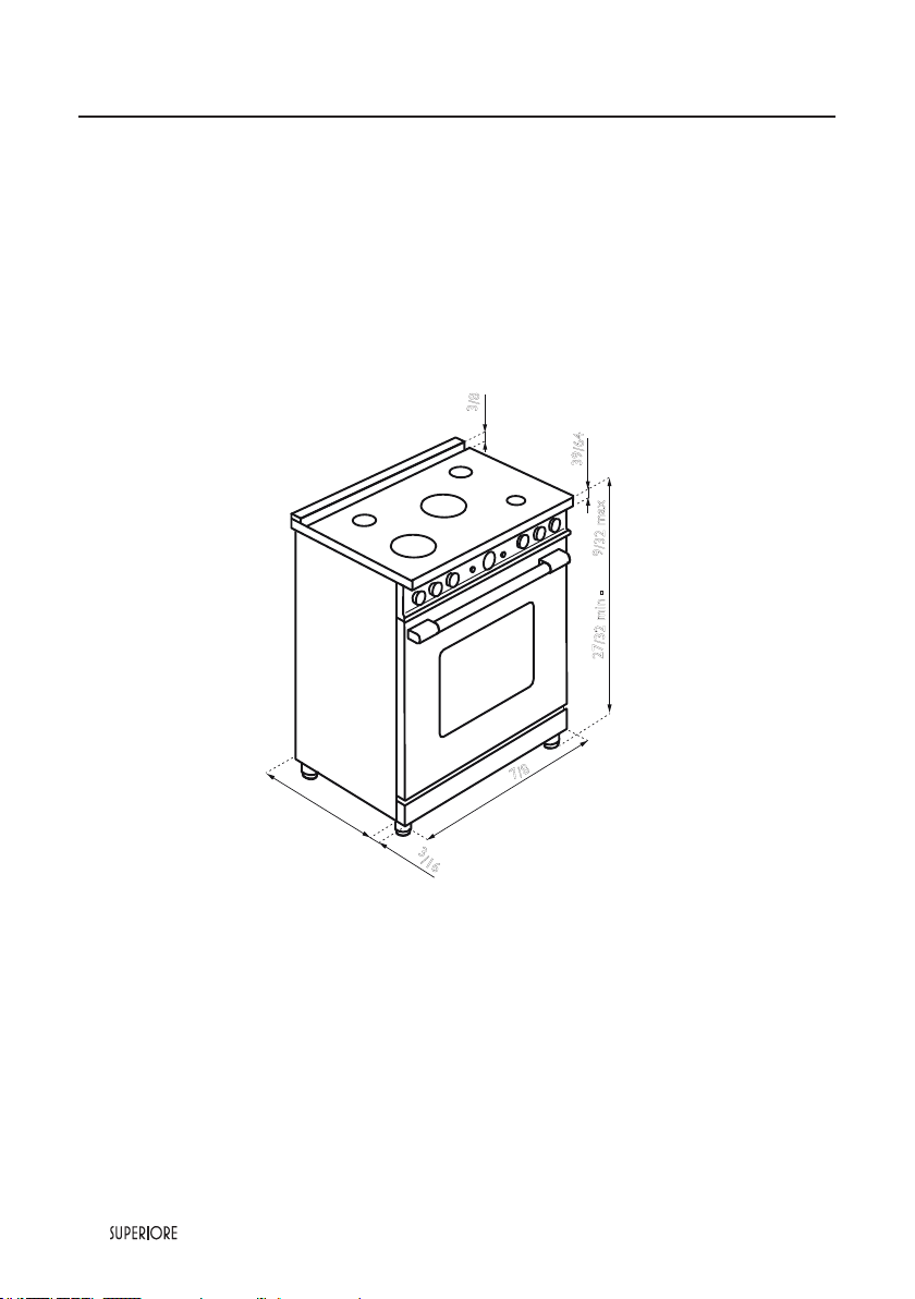
12
|
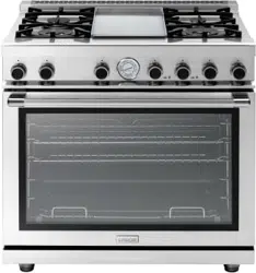
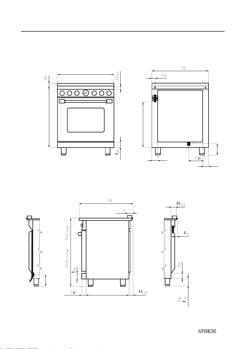
36” SUPERIORE, La Cucina Line ranges
Note: Unit shown with island trim.
Note: All gas ranges are equipped with spacer on the back (
25/64
) to prevent over
heating of the wall.
Dimensions
35"
7
/
8
23"
2"
3
/
16
1"
3
/8
1"
39
/64
35"
27
/32 min - 37"
9
/32 max
|
13
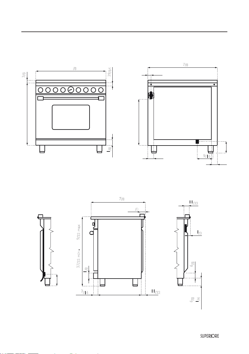
36” SUPERIORE, La Cucina Line ranges
Dimensions
1"
1
/2
5"
1"
11
/32
2"
6
/8
26"
7
/8
2"
3
/
8
23"2"
3
/16
2"
1
/8
1"
11
/32
2"
6
/8 min
4"
1
/4 max
35"
27
/32 min - 37"
9
/32 max
33"
35"
7
/
8
2"
1
/8
1"
39
/64
1"
3
/8
25"
2"
2"
Gas
1"
3
/8
35"
7
/8
Electricity
5"
5"
9
/16

14
|
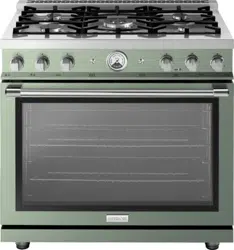
30” SUPERIORE, La Cucina Line ranges
Note: Unit shown with island trim.
Note: All gas ranges are equipped with spacer on the back (
25/64
) to prevent over
heating of the wall.
Dimensions
29"
7
/
8
23"
2"
3
/
16
1"
3
/8
1"
39
/64
35"
27
/32 min - 37"
9
/32 max
|
15
30” SUPERIORE, La Cucina Line ranges
Dimensions
25"
2"
2"
Gas
33"
1"
3
/8
29"
7
/8
29"
7
/8
Electricity
2"
1
/8
5"
5"
9
/16
1"
3
/8
1"
39
/64
1"
1
/2
5"
1"
11
/32
2"
6
/8
26"
7
/8
2"
3
/
8
23"2"
3
/16
2"
1
/8
1"
11
/32
2
"
6
/8 min
4
"
1
/4 max
35"
27
/32 min - 37"
9
/32 max
16
|
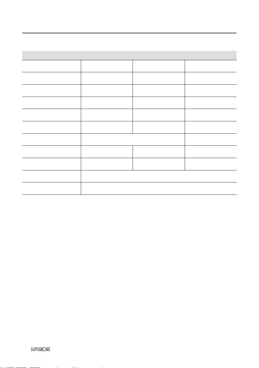
Specifications Technical data, 36” models
Burners - injectors and volume, ranges 36‘‘
Natural 4’’ LP/Propane 11’’ By-pass
Inj. W BTU/h Inj. W BTU/h
Ø
W BTU/h
Small burner 92 - 3600 56 - 3600 28 - 1100
Medium burner (*) 117 - 6500 70 - 6500 34 - 1300
Large burner 155 - 11000 93 - 11000 44 - 2700
Power burner
with simmer
Ext. ring
Int. ring
137 (2)
80
- 18000
82 (2)
50
- 18000
60
27
- 4700
Total gas power 61600 -
Oven ranges 200 - 16000 115 - 16000 65 - 4400
Broil ranges 155 - 11000 92 - 11000 - - -
Feeding-all gas ranges 120 V 60 Hz 170 W
Interior dimensions 28
3/4
x
19
57/64
x
20
31/64
(*) 2 burners
|
17
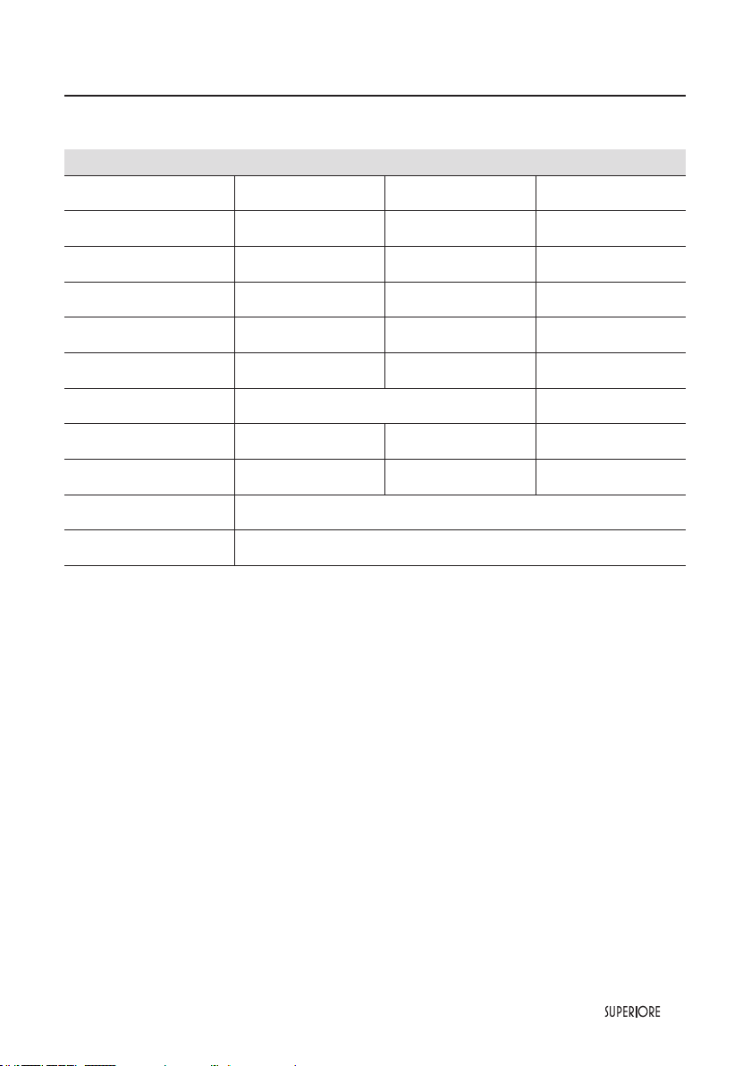
Burners - injectors and volume, ranges 30‘‘
Natural 4’’ LP/Propane 11’’ By-pass
Inj. W BTU/h Inj. W BTU/h
Ø
W BTU/h
Small burner 92 - 3600 56 - 3600 28 - 1100
Medium burner (*) 117 - 6500 70 - 6500 34 - 1300
Large burner 155 - 11000 93 - 11000 44 - 2700
Power burner
with simmer
Ext. ring
Int. ring
137 (2)
80
- 18000
82 (2)
50
- 18000
60
27
- 4700
Total gas power 61600 -
Oven ranges 180 - 14000 180 - 14000 52 - 3000
Broil ranges 135 - 8000 82 - 8000 - - -
Feeding-all gas ranges 120 V 60 Hz 170 W
Interior dimensions 24
13/64
x
19
57/64
x
20
31/64
Specifications Technical data, 30” models
(*) 2 burners
18
|
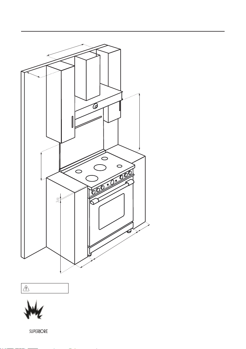
• This range may be installed directly
adjacent to existing 36” (91.4 cm)
high base cabinets.
IMPORTANT: The side trim MUST
be 3/8” (0.95 cm) above the adjacent
base cabinet countertop. This can
be accomplished by raising the unit
adjusting the legs.
• The range CANNOT be installed
directly adjacent to sidewalls,
tall cabinets, tall appliances, or
other side vertical surfaces above
36”(91.4 cm) high. There must be
a minimum of 6” (15.2 cm) side
clearance from the range to such
combustible surfaces above the 36”
(91.4 cm) counter height.
• Within the 6” (15.2 cm) side
clearance to combustible vertical
surfaces above 36” (91.4 cm),
the maximum wall cabinet depth
must be 13” (33.0 cm) and wall
cabinets within this 6” (15.2 cm)
side clearance must be 18” (45.7
cm) above the 36” (91.4 cm) high
countertop.
• Wall cabinets above the range must
be a minimum of 42” (106.7 cm)
above the range cooking surface
for the full width of the range. This
minimum height requirement does
not apply if a range hood is installed
over the cooking surface.
Note: If a range hood is installed,
wall cabinets above the range have a
different minimum clearance height.
CAUTION
Burn hazard
To avoid risk of personal injury; the use of cabinets for storage above the appliance may resultin
a potential burn hazard. Combustible items may ignite, metallic items may become hot and
cause burns. If a cabinet storage is to be provided the risk can be reduced by installing a range
hood that projects horizontally a minimum 5” (12.7 cm) beyond the bottom of cabinets.
Clearance Dimensions 36’’/30’’
36’’- 30’’
min 6"
min 6"
36"
13"
min 18"
3
/8"
36’’- 30’’
min 30"

|
19
The bottom of a standard hood should be 30” (76.2 cm) min. to 36” (91.4 cm) max to above the countertop.
This would typically result in the bottom of the hood being 66” (167.6 cm) to 72” (182.9 cm) above the oor.
Refer to the range hood installation instructions for additional information. These dimensions provide for
safe and efcient operation of the hood.
Important: There must be a minimum of 6” (15.2 cm) clearance from rear of range to a combustible wall.
Clearances from non-combustible materials are not part of the ANSI Z21. 1 scope and are not certied by
CSA. Clearances to non-combustible materials must be approved by the authority having jurisdiction.
Clearance Dimensions 36’’/30’’
20
|
Electrical Requirements
Check your national and local codes regarding this unit. This range requires120VAC/60 Hz; 4 ft. (121.9 cm),
3-wire cord with grounded 3-prong plug attached to unit. See “Electrical Connection” section for grounding
instructions. Must be fused seperately from any other circuit.
WARNING
ELECTRICAL SHOCK HAZARD
To avoid the risk of electrical shock, personal injury or death; verify electrical power is
turned off at the breaker box and gas supply is turned off until the range is installed and
ready to operate, installation by an authorized installer only.
Gas Connection
The appliance must be disconnected from the gas supply piping system during any pressure testing of that
system.
The gas supply (service) line must be the same size or greater than the inlet line of the appliance. This range
uses a 1/2” (1.3 cm) IDNPT (Sch40) inlet. Sealant on all pipe joints must be resistive to LP gas.
The range is designed specically for natural gas or liquid propane (LP) gas. Before beginning installation verify
that the model is compatible with the intended gas supply.
Manual shut-off valve:
This installer-supplied valve must be installed in the gas service line before the appliance in the gas stream
and in a location where it can be reached quickly in the event of an emergency. Any opeing behind the range
shall be sealed.
In Massachusetts: A “T” handle type manual valve must be installed in the gas supply line to the appliance.
IMPORTANT: Any conversion required must be performed by your dealer or a qualied licensed plumber or
gas service company. Please provide the service person with this manual before work begins.
Pressure Regulator
• All ranges have a pressure regulator on the incoming service line for safe and efcient operation, since
service pressure may uctuate with local demand.
External regulators are not required on this range since a regulator is supplied with each unit. Under no
condition by-pass this regulator.
• Manifold pressure should be checked with a manometer, natural gas requires 4.0”W.C.P. and LP gas
requires 11.0” W.C.P. Incoming line pressure upstream from the regulator must be 1” W.C.P. higher than
the manifold pressure in order to check the regulator. The regulator used on this range can withstand a
maximum input pressure of 1/2” PSI (14.0” W.C.P.). If the line pressure is in excess of that amount, a step
down regulator will be required.
Electrical & Gas Requirements
|
21
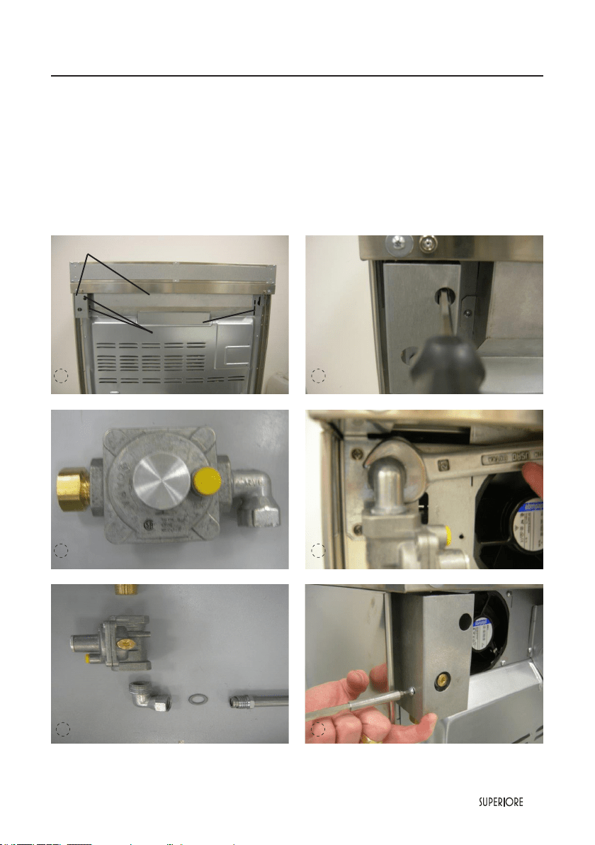
COVERS
SCREWS
1 2
3 4
Gas Requirements
TO INSTALL PRESSURE REGULATOR
1 - Remove the 2 covers on the back by unscrewing the 3 screws indicated at pag 21 step 1 an 2.
2 - Ttake from the top of packaging the parts shown in the picture at pag 21 step 5 to assemble the pressure
regulator as indicated at pag 21 step 3.
3 - Screw the assembled pressure regulator on the range like shown on picture at pag 21 step 4. Pay attention
to the vertical alignement of the same pressure regulator.
4 - Reassemble the cover on the back on the range like shown in picture at pag 21 step 6.
5 6
22
|
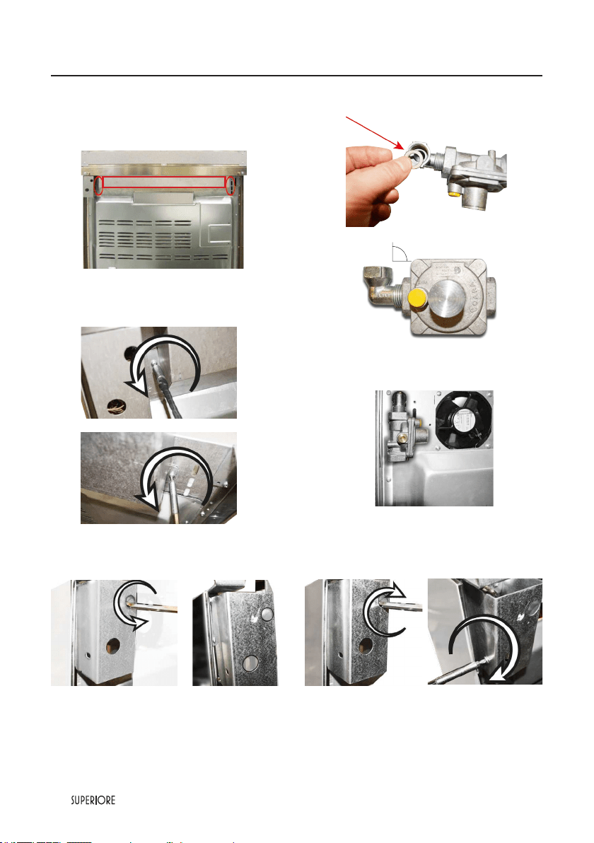
REMOVE
To perform the following operation is necessary
to have eavy access to the back the range. While
performing this plese note that the range must not
be connected to the power and or gas lines.
1 - Remove the main back cover unscrewing the
two screws.
2 - Remove the gas regulator back cover unscrewing
the single screw.
3 - Fit the elbow on the regulator. Put the gasket,
in it.
4 - Connect the regulator to the manifold and re-
install the main back cover.
5 - Re-install the gas regulator backcover and x it
with two screws.
Gas Requirements
|
23
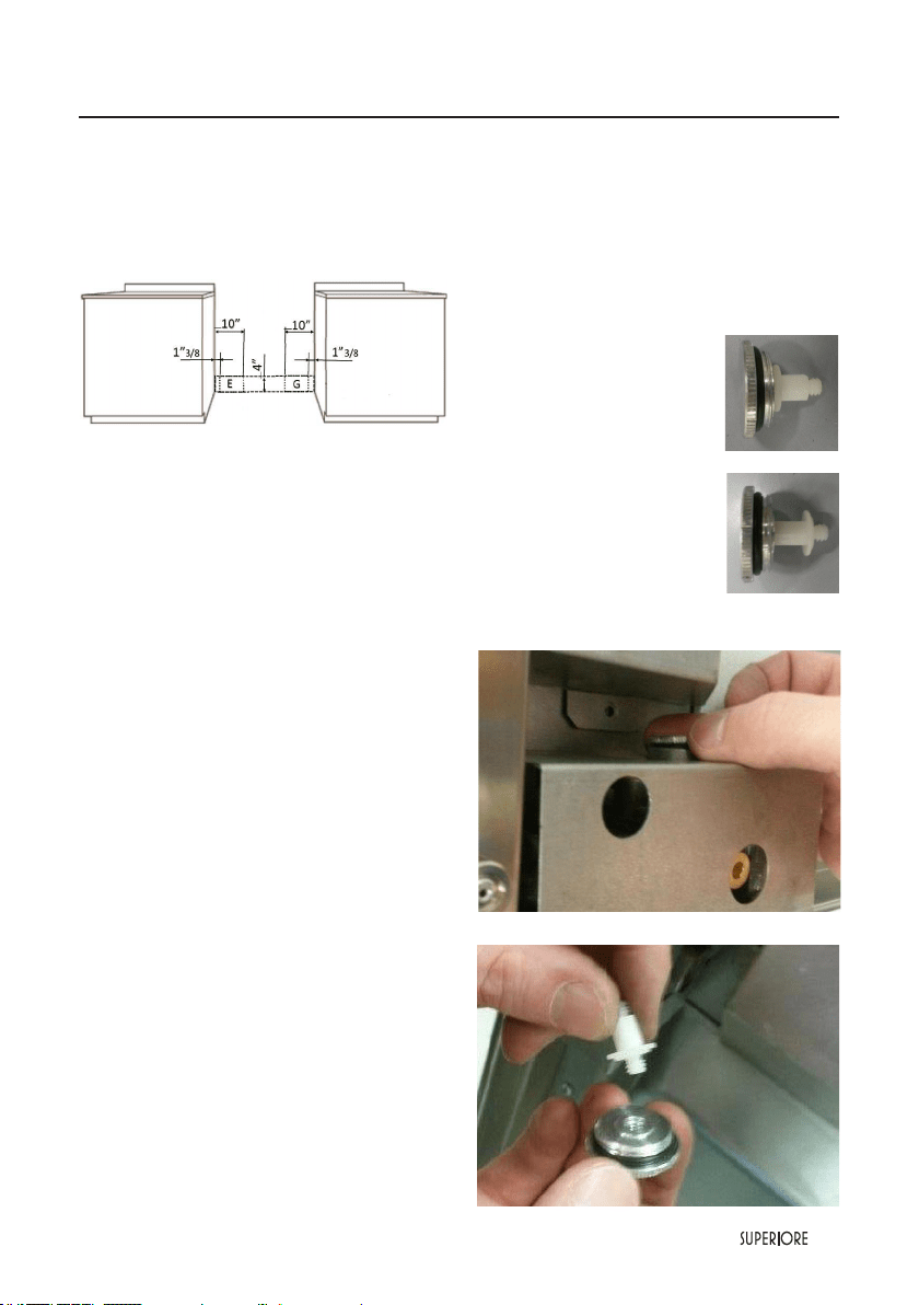
Flexible Connections: if the unit is to be installed
with exible couplings and/or quick-disconnect
ttings, the installer must use a heavy-duty AGA
design-certied exible connector or at least1/2”
(1.3 cm) ID NPT (with suitable strainreliefs) in
compliance with ANSI Z21.41and Z21.69.
G - area for gas connection
E - area for electric connection
In Canada: CAN 1-6, 10-88 metal connectors for
gas appliances and CAN 1-6.9 M79 quick disconnect
devices for use with gas fuel.
In Massachusetts:This appliance must be installed
with a 36” (3-foot) long exible gas connector.
GAS CONVERSION WARNING!
Before carrying out this operation, disconnect the
appliance from gas and electricity. Gas conversion
shall be conducted by a factory-trained professional.
Call the customer service hotline to identify a
factory-trained professional near your home. The gas
conversion procedure for this range includes 6 steps:
1. Pressure regulator
2. Surface burners
3. Main oven burner
4. Broiler burner
5. Visual checks prior to closure of oven bottom panel
6. Adjustment of minimum setting.
The conversion is not completed if all 6 steps have
not been concluded properly. Before performing
the gas conversion, locate the package containing
the replacement nozzle shipped with every range.
IMPORTANT: each nozzle has a number
indicating its ow diameter printed on the body.
Consult the table on “Specications Technical data
“paragraph for matching nozzles to burners. Save
the nozzles removed from the range for future use.
STEP1:PRESSURE REGULATOR
The pressure regulator supplied with the appliance
is a convertible type pressure regulator for use
with Natural Gas at a nominal outlet pressure of
4” w.c. or LP gas at a nominal outlet pressure of
11” w.c. and it is pre arranged from the factory to
operate with one of these gas/pressure as indicated
in the labels afxed on the appliance, package and
Instruction booklet.
To convert the regulator for use with other liquid
propane LP gas:
1. Unscrew by hand the upper
cap of the regulator, remove the
white plastic attachment from
the cap, reverse its direction
and screw it again rmly against
the cap. The white plastic
attachment must be turned as
follow for NATURAL GAS and
as reversed for LP/PROPANE
GAS
2. Screw by hand the metal cap
in the original position on the
regulator.
LP/PROPANE GAS
Gas Requirements
NATURAL GAS
24
|
Gas Requirements
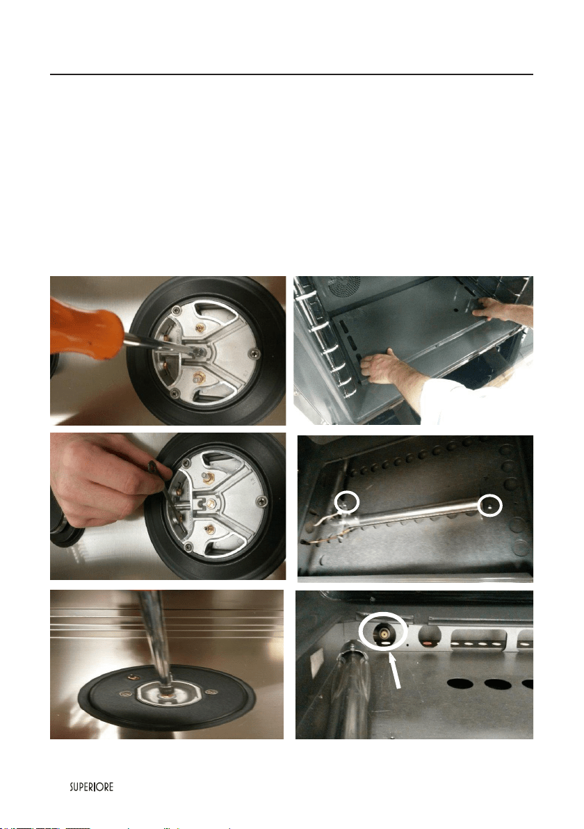
STEP 2: SURFACE BURNERS
To replace the nozzles of the surface burners, lift
up the burners and unscrew the nozzles shipped
with the range using a 7 mm (sochet wrench).
Replace nozzles using the conversion set supplied
with the range or by a Tecno authorized parts
warehouse. Each nozzle has a number indicating
its ow diameter printed on the body. Consult the
table on “Specications Technical data” paragraph
for matching nozzles to burners.
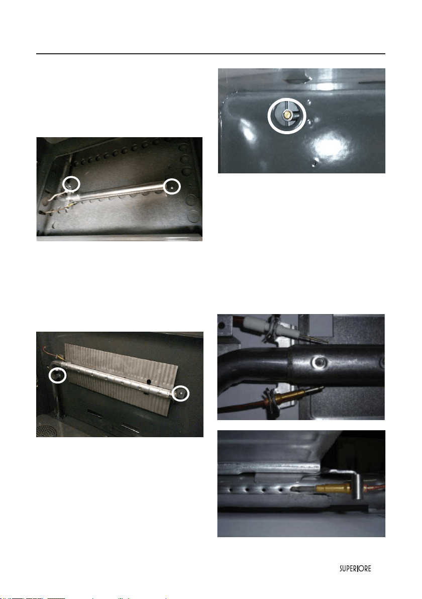
STEP 3 OVEN BURNER
To replace the nozzles of the main oven burner,
start by removing the bottom panel of the oven.
Loose the 2 screw located on the left and right sides of
the burner and the burner from its support.
ATTENTION: pay extra attention to avoid damage
to the igniter and thermocouple.
Unscrew the nozzle located inside the gas tting using
a 10 mm or 7 mm socket wrench. (It depends on type
of injector).
|
25
Gas Requirements
Replace the nozzle using the conversion set supplied
with the range or by a Superiore authorized parts
warehouse. Each nozzle has a number indicating its
ow diameter printed on the body. Consult the table
on “Specications Technical data “ paragraph for
matching nozzles to burners.
Air adjustment is not needed.
STEP 4 BROILER BURNER
Loosen the 2 screws on left and right sides and pull
out the burner from its support burner from its
support.
ATTENTION: pay extra attention to avoid
damage to the igniter and thermocouple.
Using a 7 mm or 10 mm sochet wrench to unscrew
the nozzle. Replace the nozzle using the conversion
set supplied with the range or by a Tecno authorized
parts warehouse. Each nozzle has a number
indicating its ow diameter printed on the body.
Consult the table on “Specications Technical data “
paragraph for matching nozzles to burners.
ATTENTION: Air adjustment is not needed.
STEP 5 VISUAL CHECKS
Before reinstalling the bottom panel, the following
visual check must be performed to ensure that
the conversion has been carried out properly and
without damage to other components of the range.
OVEN IGNITER AND THERMOCOUPLE
POSITION
The appropriate gap between the tip of the spark
plug or thermocouple and the burner shall be
approximately 1/8’’.
For 30” range’s
26
|
Gas Requirements
The tip of the spark plug or thermocouple must
fully overlap at
least the rst gas emission hole of the burner.
After performing all these visual checks, reinstall
the bottom panel of the oven compartment and
proceed to setting the minimum for each burner.
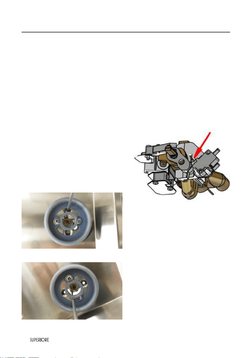
STEP 6: MINIMUM FLAME ADJUSTMENT
WARNING! These adjustments should be made
only for use of the appliance with natural gas. For
use with liquid propane gas, the By-pass screw must
be fully turned in a clockwise direction.
SURFACE BURNERS
1. Light one burner at a time and set the knob to the
MINIMUM position (small ame).
2. Remove the knob.
3. The range is equipped with a safety valve. Using a
small size slotted screwdriver, locate the By-pass
screw valve on the valve body and turn it to the
right or left until the burner ame is adjusted to
desired minimum.
4. Make sure that the ame does not go out when
switching quickly from the MAXIMUM to the
MINIMUM position.
For surface worktop burners
For simmer burners, on the tap in the right
OVEN BURNER
1. Set the oven temperature control knob to the
MAXIMUM setting.
2. Close the oven door and operate the oven for at
least 10 minutes.
3. Set the knob to the MINIMUM setting
4. Remove the knob.
5. With a slotted screwdriver turn the choking
screw (bypass screw at the left side of the
thermostat bar) and, while observing the ame
at the same time through the bottom oven
porthole, evaluate the consistency of the ame
so it remains on when switching quickly from
MINIMUM to MAXIMUM setting.
|
27
General Information
READ AND FOLLOW ALL WARNING AND CAUTION INFORMATION WHEN
INSTALLING THIS APPLIANCE.
• All openings in the wall behind the appliance and in the oor under the appliance must be sealed.
• Do not obstruct the ow of combustion and air ventilation.
CAUTION
Avoid any damage to oven vents.
The vents need to be un obstructed and open to provide proper airow for optimal oven performance.
CAUTION
The cooling fans should be working when the unit is in operation, until the appliance has reduced its external
temperatures. If you notice the cooling fans are not operating or you observe unusual or excessive noise
coming from the cooling fans, contact a SUPERIORE Service Center before continuing operation. Failure to
do so can result in damage to the oven or surrounding cabinets.
Moving, Handling and Unpacking
Remove and discard all packing materials, including cardboard and tape on the outside and inside of the range.
Remove the burner grates and styrofoam off the top cooking surface. Be sure to remove the burner caps
packaged in styrofoam below the burner grates.
Do not discard the anti-tip metal bracket supplied with the range.This is the anti-tip device and must be
installed with the unit. Refer to“Anti-tip Device Installation” section.
Some stainless steel parts may have a plastic protective wrap which must be peeled off. The interior should
be washed thoroughly with hot, soapy water to remove lm residues and any dust or debris before being
used, then rinsed and wiped dry.
Solutions stronger than soap and water are rarely needed.
28
|
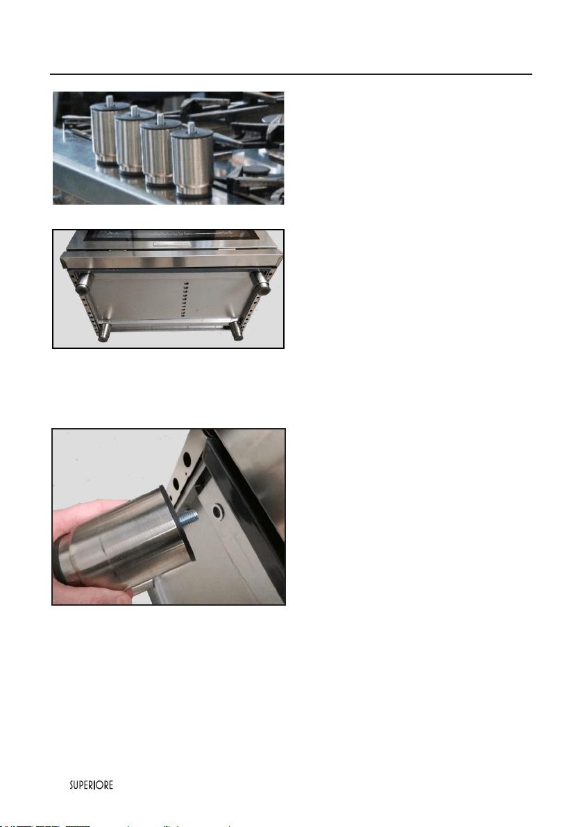
Leg Installation/Adjustments/Alignment
Superiore ranges must be used only with the legs
properly installed.
Four height adjustable staineless steel legs,
assembled under the bottom of the range
Four height adjustable staineless steel legs are
delivered with the range in the polysterene
container situated over the appliance.
Before installing the legs, position the appliance
near its nal location as the legs are not suitable
for moving the appliance over long distances.
After unpacking the range, raise it enough to
insert the legs in the appropriate receptacles
situated on the lower part of the appliance.
Lower the range gently to keep any undue strain
from legs and mounting hardware. If possible use
a pallet or lift jack instead of tilting the unit.
NOTE: please install the front legs rst, and
then the back legs, to avoid any damage to
the unit.
Adjust leg height to the desired level by twisting
the inside portion of the leg assembly until the
proper height is reached. Check with a level that
the worktop allignement is perfectly level.
Insert the legs in the appropriate
receptacles
Remember that is indicated to set the high
corner of range so that the top of side trim is
3/8” (0.95 cm) above countertop.
(see paragraph
“Dimension”)
|
29
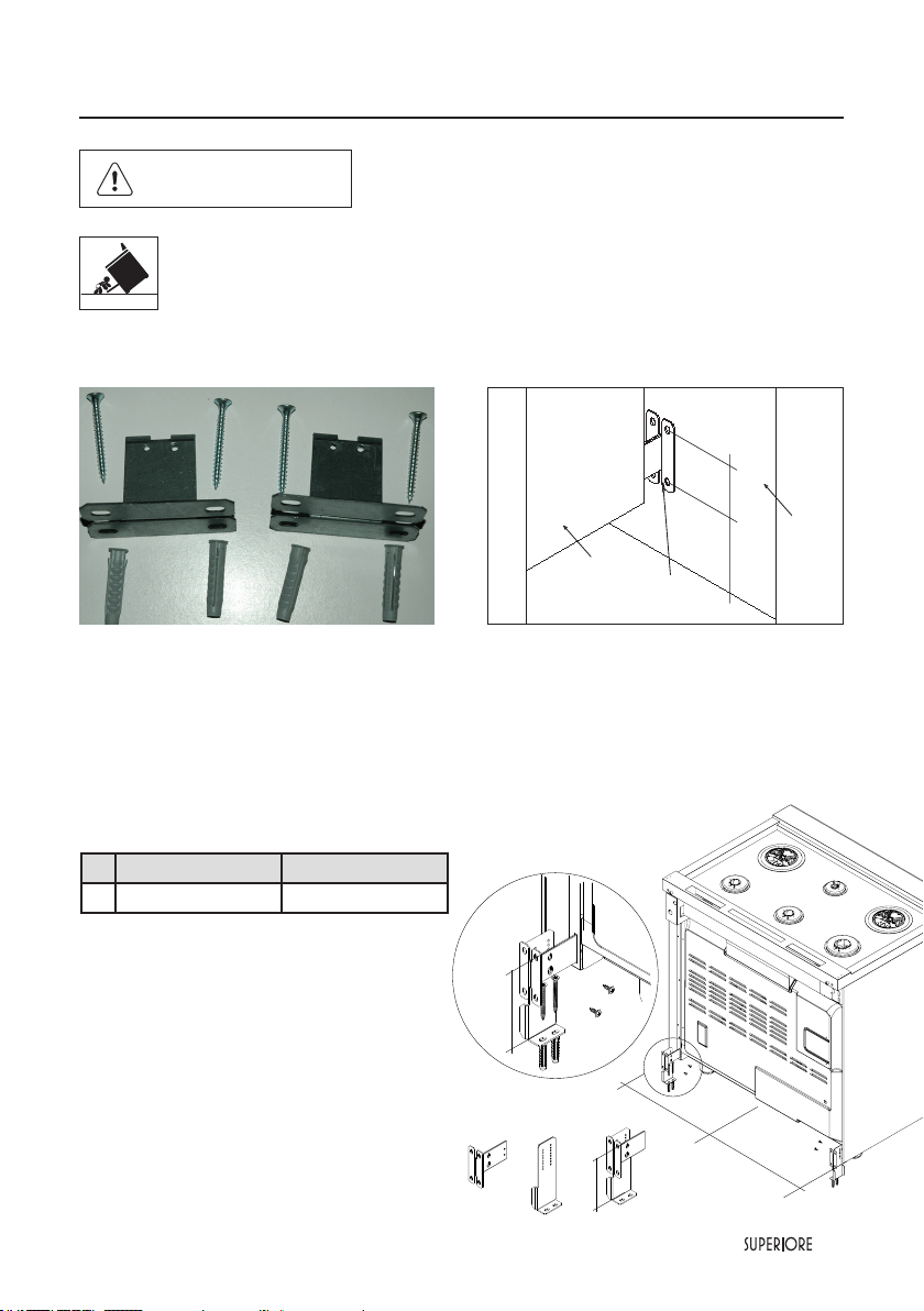
Anti-tip Device Installation
WARNING
TIPPING HAZARD:
To reduce the risk of property damage or personal injury; install anti-tipping device
provided in accordance with the installation instructions in this document.
Device must be engaged properly to prevent product from tipping over.
TIPPING
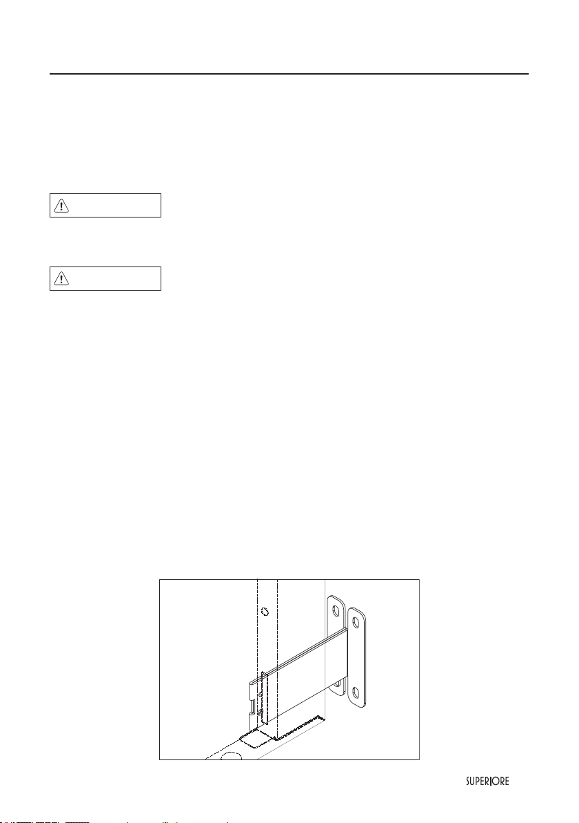
Kit enclosed with the range. Mark and drill holes
where the bracket will be located.
GROUND FIXING BRACKETS
Adjust the range height by regulating the feet , until you reach the desired cooktop height.
Fix the components B to the ground , according to width Y (see below chart).
30” 36”
Y 28”
35/64
34”
17/32
Insert the component A in the hole in
the back of the cooker and measure the
distance X (from the upper edge of the
hole to the ground).
Fix A to B with the screws , keeping the
distance X.
Repeat the same sequence on the other
side of the product.
Slide the range towards the wall until the
brackets A are well into the holes in the
back of the product.
Measure from oor to the anti-tip bar located in a
slit on the back of the range.
A
X
B
Y
=
=
X
30
|
Installation/Door removal
NOTICE
DO NOT use the handle or oven door to lift the oven. DO NOT lift or carry the door by the handle.
Removing the door must be done by your dealer, a qualied licensed plumber, or certied gas installer.
1
2
3
Door Removal
1)- Open the door completely. Place the pins, supplied
with unit, in pin hole. For personal safety, ONLY
use pins supplied with the unit.
2)- Grasp the door as indicated in the photos below
and turn up until you perceive the block.
3)- Lift the door up and extract.
|
31
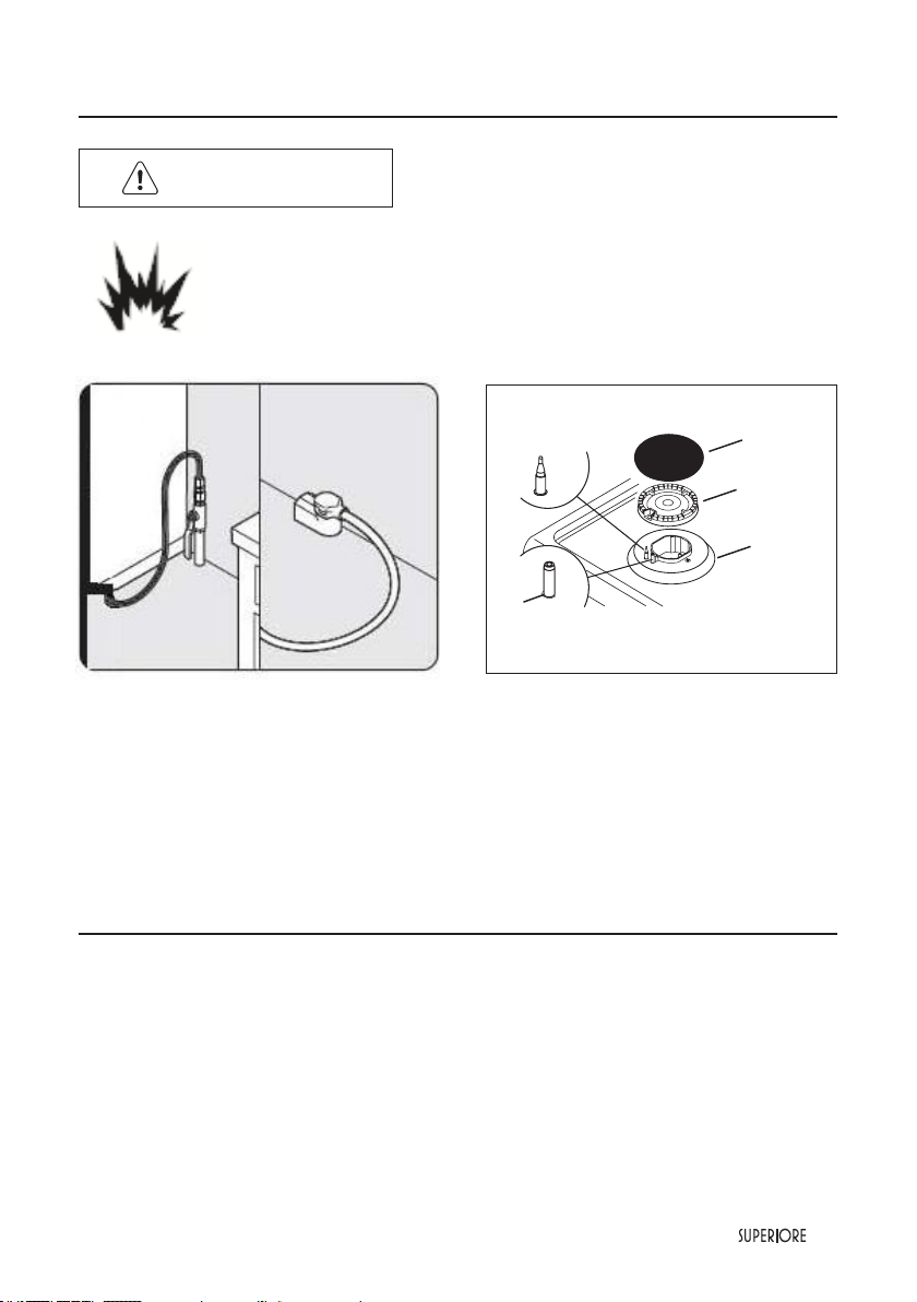
Connecting Gas & Electric
DANGER
GAS LEAK HAZARD
To avoid risk of personal injury or death; leak testing of the appliance must
be conducted according to the manufacturer’s instructions. Before placing
appliance in operation, always check for gas leaks with soapy water solution.
• DO NOT USE AN OPEN FLAME TO CHECK FOR GAS LEAKS.
Connect gas and electrical.
Before placing appliance in operation, always check
for gas leaks. This must be performed by your dealer,
a qualied licensed plumber, or gas service company.
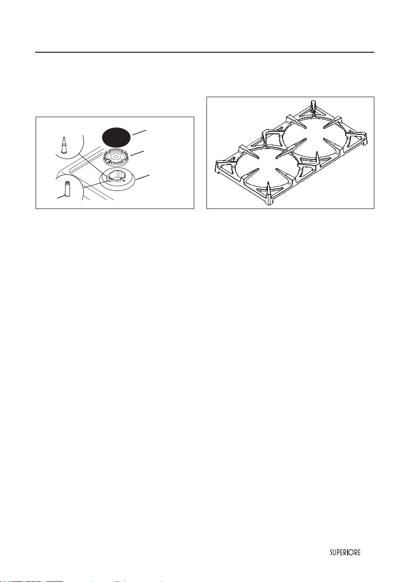
Burner caps are packed in styrofoam top pack
with the grates. Place burner on top of range.
Place burner grate on top of burner cap and grate
support.
•All stainless steel body parts should be wiped with hot, soapy water and with a liquid cleaner designed
for this material. If buildup occurs, DO NOT use steel wool, abrasive cloths, cleansers, or powders! If it is
necessary to scrape stainless steel to remove encrusted materials, soak with hot, wet cloths to loosen the
material, then use a wool or nylon scraper. DO NOT use a metal knife, spatula, or any other material tool
to scrape stainless steel! Scratches arealmost impossible to remove.
Final Preparation

32
|
Performance Checklist
Worktop burner knob
OFF
= Closed position
= “Full on” position (High ame)
= “Reduced rate” position (Low flame)
Worktop burner knob + simmer
OFF
= Closed position
=“Full on” position internal ring
= “Full on” position esternal ring
For 30” ranges only
OFF
= Closed position
from MIN
to MAX (300-
450 °F)
= Oven temperatures
Broil = Broil
For 36” ranges only
OFF
= Closed position
from MIN to MAX
(300 - 500 °F)
= Oven temperatures
Broil = Broil
A qualied installer should carry out the following checks:
• Check top burner ignition.
Push and turn the knob “Full on“ position. The low ame should light at every port.
• Check oven bake function bake burner on full power.
• Check convection broil function broil burner at full power.
• Check convection fans function convection fans comes on when switch is turned on.
• Convection fans do not operate when broils working.

|
33
Before Using the Range
All products are wiped clean with solvents at the factory to remove any visible signs of dirt, oil, and grease
which may have remained from the manufacturing process. Before starting to cook, clean the range thoroughly
with hot, soapy water. There may be some burn off and odors on rst use of the appliance this is normal.
Oven
Important! Before first use, wipe interior with soapy water and dry
thoroughly. Then set the oven selector to bake, the thermostat to 450°F or 500 °F, and operate
for an hour.
This appliance is certied by Star-K to meet strict regulations in conjunction with specic instructions found
on www.star-k.org
34
|
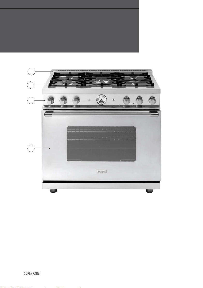
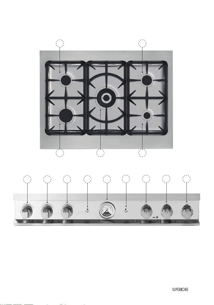
A. Worktop Profile
A1. If supplied with island trim
B. Worktop
1. Left front large burner 1100 Btu/h
2. Left rear medium burner 6500 Btu/h
3. Center power burner 18000 Btu/h
4. Right front small burner 3600 Btu/h
5. Right rear medium burner 6500 Btu/h
C. Control Panel
6. Left front large burner control knob
7. Left rear medium burner control knob
8. Center power burner zone control knob
9. Switch light
10. Thermometer
11. Switch convection
12. Oven temperature control knob
13. Right rear medium burner control knob
14. Right front small burner control knob
D
C
B
A1
Range Features:
RL361...
|
35
1
5
3 4
2
6
8
13
7
12
9
14
10
11
36
|
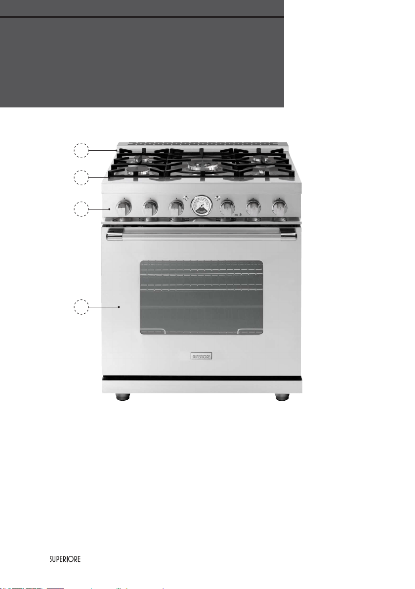
Range Features:
RL301...
A. Worktop Profile
A1. If supplied with island trim
B. Worktop
1. Left front large burner 1100 Btu/h
2. Left rear medium burner 6500 Btu/h
3. Center power burner 18000 Btu/h
4. Right front small burner 3600 Btu/h
5. Right rear medium burner 6500 Btu/h
C. Control Panel
6. Left front large burner control knob
7. Left rear medium burner control knob
8. Center power burner zone control knob
9. Switch light
10. Thermometer
11. Switch convection
12. Oven temperature control knob
13. Right rear medium burner control knob
14. Right front small burner control knob
D
C
B
A1

|
37
6 7 8 13 14
1
5
3 4
2
9
10
11
12
38
|
Surface Cooking Tips
Your range is equipped with a variety of different sized surface burners. Below is a guide for which burners
work best for certain cooking applications:
Note: models with induction zones are provided only with the burners on the right.
Use low or medium ame heights when cooking in vessels that are poor conductors of heat, such as glass,
ceramic, and cast-iron. Reduce the ame height until it covers approximately 1/3 of the cooking vessel
diameter. This will ensure more even heating within the cooking vessel and reduce the likelihood of burning
or scorching the food.
• Reduce the ame if it is extending beyond the bottom of the cooking vessel. A ame that extends along
the sides of the vessel is potentially dangerous, heats the utensil handle and kitchen instead of the food,
and wastes energy.
• Reduce the ame height to the minimum level necessary to perform the desired cooking process. Remember
that food cooks just as quickly at a gentle boil as it does at a rolling boil. Maintaining a higher boil than is
necessary wastes energy, cooks away moisture, and causes a loss in food avor and nutrient level.
• The minimum pot or pan (vessel) diameter recommended is 6” (15 cm) on the larger burners. Pots or pans
as small as 4” (10 cm) should be used on the smaller burners.
Cooking Vessels
Each cook has his or her own preference for the particular cooking vessels that are most appropriate for
the type of cooking being done.Any and all cooking vessels are suitable for use in the range and it is not
necessary to replace your present domestic vessels with commercial cookware. This is a matter of personal
choice. As with any cookware, yours should be in good condition and free from excessive dents on the
bottom to provide maximum performance and convenience.
Note: When using big pots and/or high ames, it is recommended to use the front burners. There is more
room in the front and potential cleanup at rear of appliance due to staining or discoloration will be minimized.
Burner Use
central 18.000 BTU Quick water boiling
Deep-fat frying in large utensil
central simmer 750 BTU Melting small quantities
Steaming rice
Simmering sauces
front right 3.600 BTU Melting large quantities
Low-temperature frying (eggs, etc.)
Simmering large quantities
Heating milk, cream sauces, gravies,and puddings
rear left and rear right 6.500 BTU Sauteing and browning, braising, and pan frying
Maintaining slow boil on large quantities
front left 11.000 BTU High-temperature frying
Pan broiling
Maintaining fast boil on large quantities
Surface Operation

|
39
Lighting Burners
All burners are ignited by electric ignition.
There are no open-ame, “standing” pilots.
Work-top Burners
To light the surface burners, push and turn
the appropriate control knob anticlockwise
to maximum ow position
. This control
is both a gas valve and an electric switch.
When gas is permitted to ow to the
burners, the electric igniters start sparking.
On all surface igniters you should hear a
“clicking” sound. If you do not, turn off the
control and check that the unit is plugged in
and that the fuse or circuit breaker is not
blown or tripped.
Within a few moments, enough gas will have
traveled to the burner to light. When the
burner lights, turn the burner control to any
position from maximum
to minimum
ow position to adjust the ame size. Setting the proper ame height for the desired cooking process
and selecting the correct cooking vessel will result in superior cooking performance, while also saving time
and energy.
Power burner with simmer
The range is provided with a powr burner with simmer, a special burner featuring a very high exible range
of cooking settings: from 750 Btu/h for simmering, melting or steaming rice, to 18000 Btu/h for the most
powerful performance.
To light the surface burners, push and turn the appropriate control knob anticlockwise to maximum power
of inner ring.
The inner ring lights at its maximum power. Then you can continue to use only the inner ring and adjust the
ame power by turning the control knob from
to position. If you need to light on also the external
ring, continue to turn anticlockwise the knob and make a little pressure on it in order to cross the lock
located after the minimum power position of internal ring. The external burner lights on; ame is adjustable
turning the knob from
to position.
Worktop burner knob + simmer
OFF
= Closed position
= “Full on” position
internal ring
= “Full on” position
esternal ring
Burners Operation

40
|
Oven Functions and Settings
BAKE (Natural Airflow Bake)
Use this setting for baking, roasting, and casseroles.
CONVECTION BAKE
Use this setting to bake and roast foods at the same time with minimal taste transfer.
BROIL
Use this setting for broiling dark meats at 1” thickness or less where rare or medium doneness is desired.
DEFROST
Use this function to defrost foods.
LIGHT
Use this function to see the interior of the cavity.
|
41
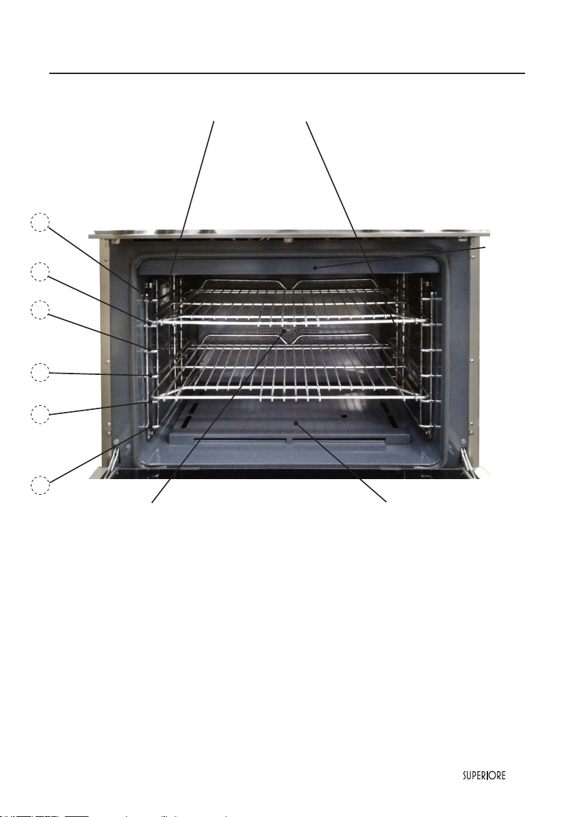
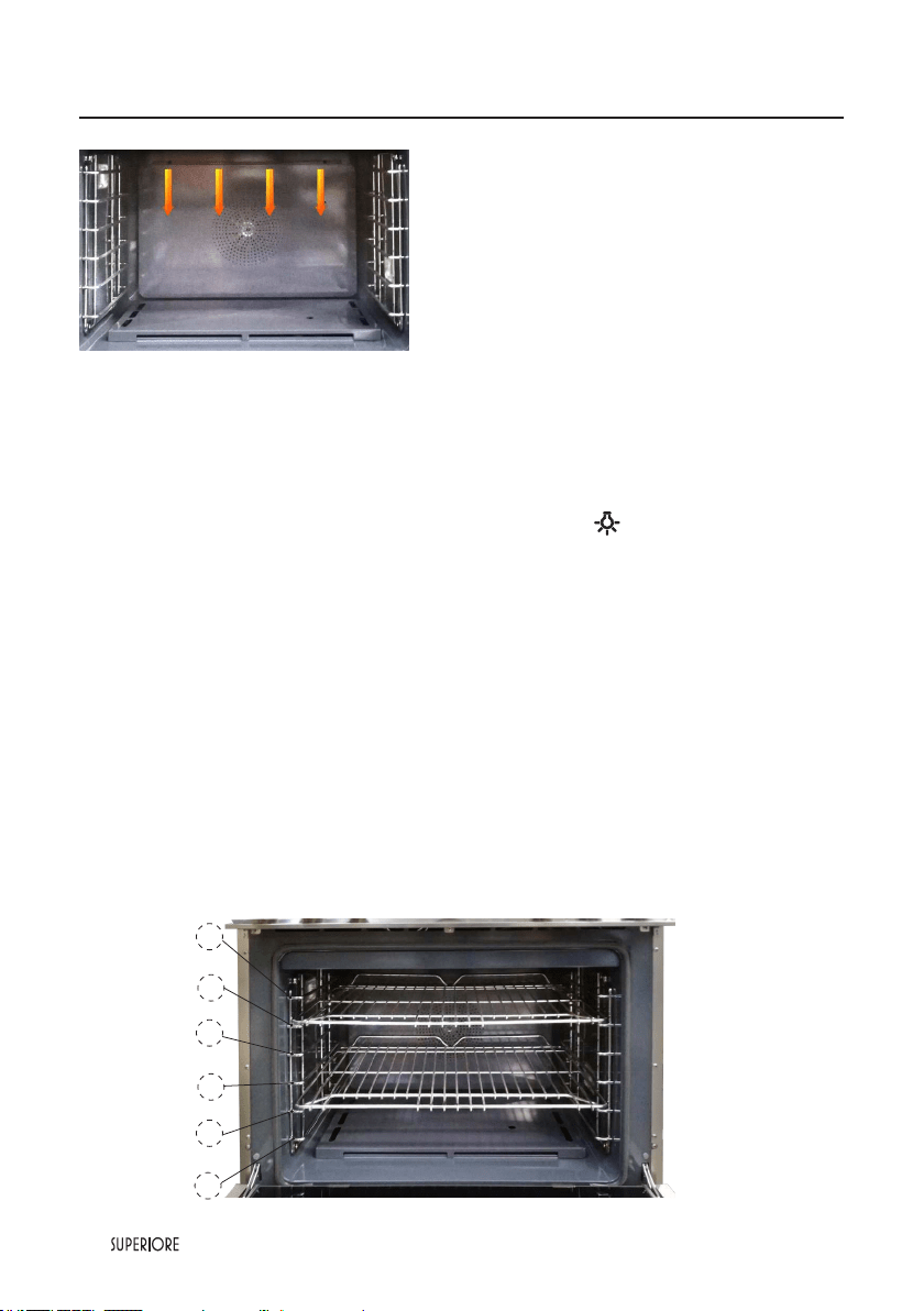
Oven Features
Rack Positions 30’’ and 36” ranges
The oven has six rack positions and is equipped whith two racks.
Position 1 is the farthest from the oven bottom. Position 6 is the closest to the oven bottom. The racks can
be easily removed and arranged at various levels. For better results with conventional baking, DO NOT
use more than one rack at a time. It is also recommended, when using two racks, to bake with the racks in
positions 2 and 4 or positions 3 and 5.
Bake burner
Oven Lights (x2)
Broiler
One fans
1
2
3
4
5
6
42
|
Oven Preheat
The oven temperature can reach a temperature of aprox 400°F in 14 minutes in static function. Please
consider this during the pre-heat process of the oven.
Conventional vs Convection Cooking
Because of variations in food density, surface texture and consistency, some foods may be prepared more
successfully using the conventional bake setting. For this reason, conventional baking is recommended
when preparing baked goods such as custard. The user may nd other foods that are also prepared more
consistently in conventional bake. It is recommended to use this function for single-rack baking.
Please note that to pre-heat our SUPERIORE all-gas ovens, convention fan(s) MUST NOT be
used; its/theirs use will slow down pre-heat times.
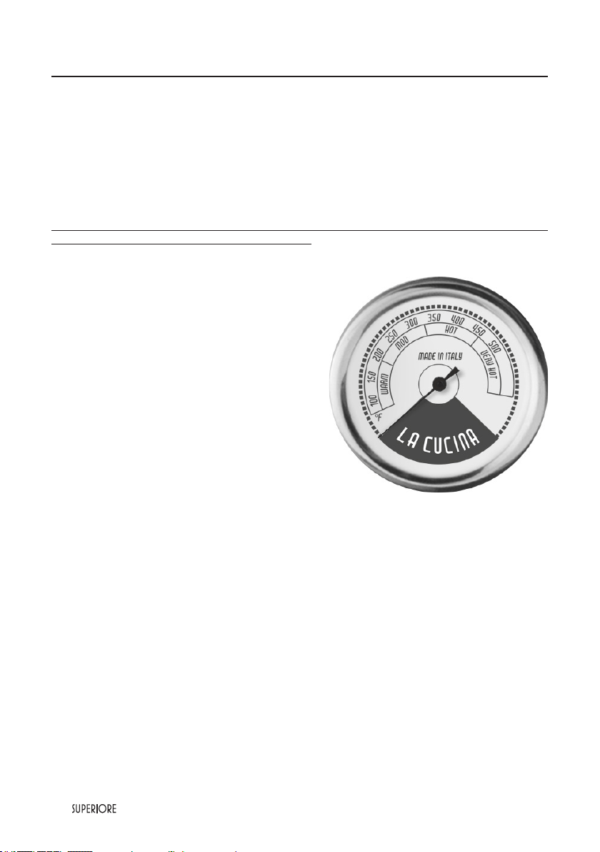
Analog Thermometer
(available on 36” and 30’’ ranges only)
This is not an electrical device, so it even works if
the range is not connected to the power outlet. This
thermometer roughly shows the inner temperature of
the main oven when this one is operated and it can have
a deviation according to the type of cooking and the type
of oven function. It isn’t a control of inner temperature.
The control of the temperature is always done
by thermostat, that is activated by the knob and that
has on it the oven target temperatures.
Using the Oven
|
43
Baking
BAKE (Natural Airflow Bake)
Full power heat is radiated from the bake burner in the bottom of the oven cavity and is circulated with
natural airow. This function is recommended for single rack baking. Many cook books contain recipes
to be cooked in the conventional manner. Conventional baking is suitable for dishes that require a high
temperature. Use this setting for baking and casseroles.
To Use BAKE Function
1. Arrange the oven rack in the desired position
before turning the oven on and close the
door.
2. Push and hold the oven control knob
for at least one second. Release and turn
it anticlockwise, setting the desidered
temperature. This sequence must be
performed within seven seconds. If you hear
a clicling sound while lighting up the oven,
this is appropriate.
Note: if the oven does not light up after ve attempts, open the oven door and let the gas out; for your safety,
open the window of the kitchen.
Baking Tips
• Make sure the oven racks are in the desired position before you turn on the oven.
• DO NOT open the door frequently during baking. Look through the door
window to check doneness whenever possible. If you must open the door, the best time is during the last
quarter of the baking time.
• Bake to the shortest time suggested and check for doneness before adding more time. For baked food, a
stainless steel knife placed in the center of the product should come out clean when done.
• Use the pan size and type recommended by the recipe to ensure best results. Cakes, quick breads, mufns, and
cookies should be baked in shiny, reective pans for light, golden crusts. Avoid the use of old, darkened pans.
Warped, dented, stainless steel and tin-coated pans heat unevenly and will not give uniform baking results.
Food Pan size Single rack position Temperature Time (min)
ENTREES
Eggs rolls Cookie sheet 3 or 4 400F°(204°C) 25-30
Fish sticks Cookie sheet 3 or 4 425°F(218°C) 10-15
Lasagna, frz Cookie sheet 3 or 4 375F°(191°C) 55-60
Pot pie Cookie sheet 3 or 4 400F°(204°C) 35-40
Gr. peppers stuffed 13”x 9” 3 or 4 375F°(191°C) 60-70
Quiche 9” round 3 or 4 400F°(204°C) 25-30
Pizza, 12” Cookie sheet 3 or 4 400F°(204°C) 15-20
Mac. & cheese, frz Cookie sheet 3 or 4 375F°(191°C) 35-40
VEGETABLES
Baked potatoes On rack 3 or 4 375F°(191°C) 60-65
Spinach soufe 1 qt. casserole 3 or 4 350F°(177°C) 45-50
Squash Cookie sheet 3 or 4 375F°(191°C) 50-55
French fries Cookie sheet 3 or 4 425°F(218°C) 20-25
*Note:
The above information is given as a guide only
44
|
Food Pan size Single rack position Temperature Time (min)
BREADS
Biscuits Cookie sheet 3 or 4 400F°(204°C) 10 -12
Yeast loaf Loaf pan 3 or 4 375F°(191°C) 30-35
Yeast rolls Cookie sheet 3 or 4 400F°(204°C) 12-15
Nut bread Loaf pan 3 or 4 375F°(191°C) 30-35
Combread 8”x 8” 3 or 4 400F°(204°C) 25-30
Gingerbread 8”x 8” 3 or 4 350F°(177°C) 35-40
Mufns Mufn tin 3 or 4 375F°(191°C) 15-20
Corn mufns Mufn tin 3 or 4 375F°(191°C) 15-20
CAKE
Angel food Tube pan 3 or 4 375F°(191°C) 35-45
Bundt Tube pan 3 or 4 350F°(177°C) 45-55
Cupcakes Mufn pan 3 or 4 350F°(177°C) 16-20
Layers, sheet 13”x 9” 3 or 4 350F°(177°C) 40-50
Layers, two 9” round 3 or 4 350F°(177°C) 30-35
Pound Loaf pan 3 or 4 350F°(177°C) 60-65
COOKIES
Brownies 13”x 9” 3 or 4 350F°(177°C) 25-30
Choc.chip Cookie sheet 3 or 4 375F°(191°C) 12-15
Sugar Cookie sheet 3 or 4 375F°(191°C) 10-12
PASTRY
Cream puffs Cookie sheet 3 or 4 400F°(204°C) 30-35
PIES
Crust, unlled 9” round 3 or 4 400F°(204°C) 10-12
Crust, lled 9” round 3 or 4 350F°(177°C) 55-60
Lemon meringue 9” round 3 or 4 350F°(177°C) 12-15
Pumpkin 9” round 3 or 4 350F°(177°C) 35-40
Custard 6-4 oz cups 3 or 4 350F°(177°C) 35-40
Baking
|
45
Baking
Solving Baking Problems
Baking problems can occur for many reasons. Check the chart below for the causes and remedies for the
most common problems. It is important to remember that the temperature setting and cooking times you
are accustomed to using with your previous oven may vary slightly from those required with this oven. If you
nd this to be true, it is necessary for you to adjust your recipes and cooking times accordingly.
Common Baking Problems/Remedies
Problems Cause Remedy
Cakes burned on the sides
or not done in center
1. Oven was too hot
2. Wrong pan size
3. Too many pans
1. Reduce temperature
2. Use recom. pan size
3. Reduce no. of pans
Cakes crack on top
1. Batter too thick
2. Oven too hot
3. Wrong pan size
1. Follow recipe
Add liquid
2. Reduce temperature
3. Use recom. pan size
Cakes are not level
1. Batter uneven
2. Oven or rack not level
3. Pan was warped
1. Distribute batter even
2. Level oven or rack
3. Use proper pan
Food too brown on botton
1. Oven door opened too often
2. Dark pans being used
3. Incorrect rack position
4. Wrong bake setting
5. Pan too large
1. Use door window to bottom
check food
2. Use shiny pans
3. Use recom. rack position
4. Adjust to conventional or
convection setting as needed
5. Use proper pan
Food too brown on top
1. Rack position too high
2. Oven not preheated
3. Sides of pan too high
1. Use recom. rack position
2. Allow oven to preheat
3. Use proper pans
Cookies too at 1. Hot cookie sheet
1. Allow sheet to coolbetween
batches
Pies burned around edges
1. Oven too hot
2. Too many pans used
3. Oven not preheated
1. Reduce temperature
2. Reduce no. of pans
3. Allow oven to preheat
Pies too light on top
1. Oven not hot enough
2. Too many pans used
3. Oven not preheated
1. Increase temperature
2. Reduce no. of pans
3. Allow oven to preheat
46
|
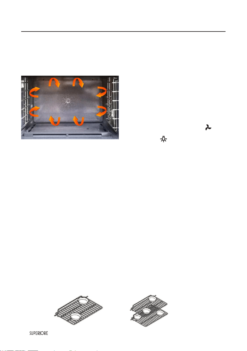
Single rack pan
placement
Multiple rack
pan placement
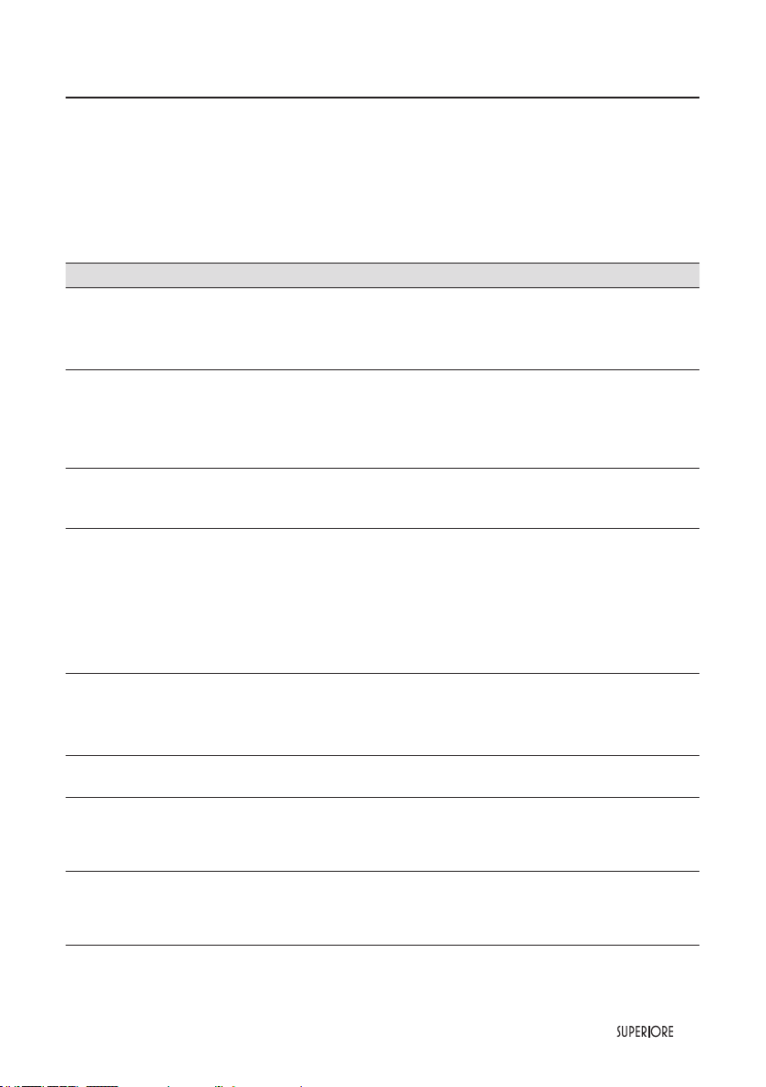
CONVECTION BAKE
Heat is radiated from the bake burner in the bottom of the oven cavity. The heated air is circulated by the fans
in the rear of the oven providing a more even heat distribution. Multiple rack use is possible for the largest
baking job. When roasting, cool air is quickly replaced searing meats on the outside and retaining more juices
and natural avor on the inside with less shrinkage. This even circulation of air equalizes the temperature
throughout the oven cavity and eliminates the hot and cold spots found in conventional ovens.
To Use CONVECTION BAKE Function
(only on main oven)
1. Arrange the oven rack in the desired position before
turning the oven on and close the door.
2. Push and hold the oven control knob for at least one
second. Release and turn it anticlockwise, setting
the desidered temperature. This sequence must be
performed within seven seconds. If you hear a clicling
sound while lighting up the oven, this is appropriate.
3. Activate the “Convection fan” pushing the
appropriate button on the control panel
4. To activate “Oven lights” psh the related button on
the control pane .
Note: if the oven does not light up after ve attempts,
open the oven door and let the gas out; for your safety, open the window of the kitchen.
Convection Cooking Tips
Convection cooking is a cooking technique which utilizes fan-forced air to circulate throughout the
entire oven cavity creating the optimum cooking environment. Cooking with convection is intended when
performing multi-rack baking and for heavier foods. Below are some tips which will allow you to get the best
results out of your oven when cooking with convection.
• As a general rule, to convert conventional recipes to convection recipes, reduce the temperature by 25°F
(10°C) when using a convection cooking function.
• Cooking times for standard baking and convection baking will be the same. However, if using convection to
cook a single item or smaller load, then it is possible to have 10-15% reduction in cooking time. (Remember
convection cooking is designed for multi-rack baking or cooking large loads.)
• If cooking items which require longer than 45 minutes, then it is possible to see a 10-15% reduction in cooking time.
• A major benet of convection cooking is the ability to prepare foods in quantity. The uniform air circulation
makes this possible. Foods that can be prepared on two or three racks at the same time include: pizza, cakes,
cookies, biscuits, mufns, rolls, and frozen convenience foods.
• For three-rack baking, use any combination of rack positions 2, 3, 4,and 5. For two-rack baking, use rack
positions 2 and 4 or positions 3 and 5. Remember that the racks are numbered from bottom to top.
Pan Placement Tips
• When using large (15”x 13”) at pans or trays that cover most of the rack, rack positions 2 or 3 produce
the best results.
• When baking on more than one rack, it is recommended to use the 3rd and 5th position for more
consistent even baking.
• Stagger pans in opposite directions when two racks and several pans are used in conventional bake. If
possible, no pan should be directly above another.
• Allow 1 to 2 inches of air space around all sides of each pan for even air circulation.
Convection Bake
|
47
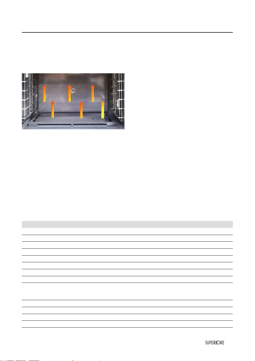
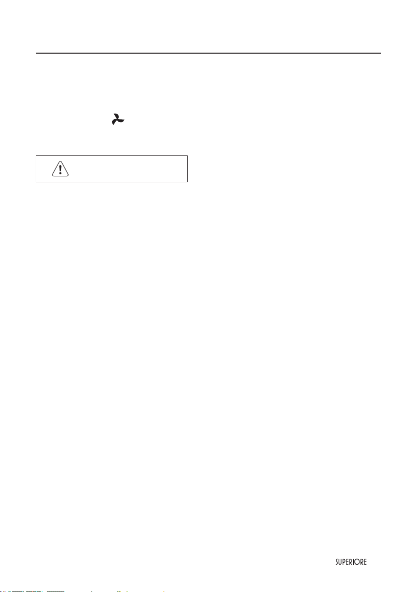
Defrost
Air is circulated by motorized fan in the rear of the oven. The fan accelerates natural defrosting of the food
without heat. To avoid sickness and food waste, DO NOT allow defrosted food to remain in the oven for
more than two hours.
1. Place the frozen food on a baking sheet.
2. Turn the selector to
and set the temperature to “OFF”.
WARNING
To avoid sickness and food waste, DO NOT allow defrosted food to remain in the oven for more than two
hours.
48
|
BROIL
Heat radiates from the broiler located at the top of the
oven cavity. The distance between the foods and the broil
elements determines broiling speed. For “fast” broiling,
foodmay be as close as 2 inches (5 cm) to the broil
element.“Fast” broiling is best for meatswhere rare to
medium donenessis desired. Use this setting for broiling
small and average cuts of meat.
Broiling Instructions
Broiling is a dry-heat cooking method using direct or
radiant heat. It is used for small, individualized cuts such
as steaks, chops, and patties. Broiling speed is determined by the distance between the food and the broil
element. Choose the rack position based on desired results.
To Use Broil
1. Arrange the oven rack in the desired position before turning the oven on and close the door.
2. Push and hold the oven control knob for at least one second. Release and turn it clockwise to the broil
position. This sequence must be performed within seven seconds. If you hear a clicling sound while lighting
up the broil, this is appropriate.
3. To activate “Oven lights” psh the related button on the control pane.
NOTE:
IF YOU SELECT THE CONVECTION FAN WILL NOT WORK! THIS MUST BE CONSIDERED
APPROPRIATE.
Broiling Tips
• A LWAYS use the enamelled tray and trivet for broiling. They are designed to provide drainage of excess
liquid and fat away from the cooking surface to help prevent splatter, smoke, and re.
• To keep meat from curling, slit fatty edge.
• Brush chicken and sh with butter several times as they broil to prevent drying out. To prevent sticking,
lightly grease broiler tray.
• Broil on rst side for slightly more than half the recommended time, season, and turn. Season second side
just before removing.
• A LWAYS pull rack out to stop position before turning or removing food.
• Use tongs or a spatula to turn meats. NEVER pierce meat with a fork, as this allows the juices to escape.
• Remove the enamelled tray from the oven when you remove the food. Drippings will bake onto the pan
if it is left in the heated oven after broiling.
Rack Positions for Broiling
Note: Position 1 is the closest to the broiler and position 6 is the closest to the oven bottom.
1=95%
2=80%
3=65%
4=50%
5=35%
6=25%
1
3
4
5
6
2
Broiling
|
49
Broiling
Broiling Chart
Type and Cut of Meat Weight Setting Rack Time (min)
BEEF
Siloin 1’’
Rare 12 oz Broil 3 4
Medium 12 oz Broil 3 5
Well done 12 oz Broil 3 6
T-Bone 3/4’’
Rare 10 oz Broil 3 4
Medium 10 oz Broil 3 6
Well done 10 oz Broil 3 8
Hamburger 1/2’’
Medium 1/4 lb. Broil 3 6
Well done 1/4 lb. Broil 3 8
CHICKEN
Bnls breast 1’’ 1/2 lb. Broil 3 15
Bone-in breast 2-3 lbs. total Broil 1 22
Chicken pieces 2-3 lbs. total Broil 3 22
HAM
Ham slice 1’’ 1 lb. Broil 3 10
PORK
Bacon Broil 2 3
FISH
Salmon steak 1 lb. Broil 2 8
Fillets 1 lb. Broil 2 8
Note: The above information is given as a guide only.

50
|
Important!
Before you start cleaning your range, please:
• Read these cleaning instructions and the ‘Safety and warnings’ section at the start of this user guide.
• Turn the range off.
• Make sure the range is a safe temperature to touch.
• Do not use a steam cleaner.
• Do not keep ammable substances in the oven.
General advice
• Wipe down the worktop and wipe out the oven after every use.
• Wipe up spills. Avoid leaving alkaline or acidic substances (such as lemon juice or vinegar) on the
surfaces.
• Do not use cleaning products with a chlorine or acidic base (ie citrus-based cleaners).
Cleaning the outside of the range
Important!
• Do not use abrasive cleaners, cloths or pads on the outside surfaces.
• Immediately wipe off any caustic cleaners if they are spilled onto the oven door handle.
Wipe the outside surfaces often, using warm water and a mild household detergent. The stainless steel may
also be cleaned with a suitable cleaner and polish.
Note: if you choose to use a commercial stainless steel cleaner, please read the label to make sure it does not
contain chlorine compounds as these are corrosive and may damage the appearance of your range.
Care and cleaning
|
51
Cleaning and Maintenance
Any piece of equipment works better and lasts longer when maintained properly and kept clean. Cooking
equipment is no exception. Your range must be kept clean and maintained properly. Before cleaning, make
sure all controls are in the “OFF” position. Disconnect power if you are going to clean thoroughly with water.
Surface Burner
Wipe up spill-overs as soon as possible after they occur and before they get a chance to burn in and cook
solid. In the event of a spill-over, follow these steps:
• Allow the burner and grate to cool to a safe temperature level.
• Lift off the burner grate. Wash in warm soapy water.
• Remove the burner cap and burner head and clean.
Burner Caps
The surface burner caps should be routinely removed and cleaned.
ALWAYS clean the burner caps after a spill-over. Keeping the burner caps clean will prevent improper
ignition and uneven ames. To clean, pull burner cap straight up from the burner base. Wipe off surface
burner caps with warm, soapy water and a soft cloth after each use. Use a non-abrasive cleanser and a soft
brush or soft Scotch Brite™ pad for cooked-on foods. Dry thoroughly after cleaning. For best cleaning and
to avoid possible rusting, DO NOT clean in dishwasher.
Burner Head
If ports on burner head are clogged, clean with a straight pin. DO NOT enlarge or distort the ports. DO
NOT use a toothpick to clean the ports.
Burner Base
The base should be wiped regularly with hot soapy water at the end of each cooling period. DO NOT use
steel wool, abrasive cloths, cleanser, or powders. To remove encrusted materials, soak the area with a hot
towel to loosen the material, then use a wooden nylon spatula. DO NOT use a metal knife, spatula, or any
other metal tool to scrape the aluminum base.
• Wipe up any spills which remain on the sealed top surface.
• Replace burner cap, burner head, and grates after drying thoroughly.
Control Panel
DO NOT use any cleaners containing ammonia or abrasives. They could remove the graphics from
the control panel. Use hot, soapy water and a soft clean cloth.
Oven Surfaces
Several different nishes have been used in your oven. NEVER USE AMMONIA, STEEL WOOL PADS
OR ABRASIVE CLOTHS,CLEANSERS, OVEN CLEANERS, OR ABRASIVE POWDERS. THEY CAN
PERMANENTLY DAMAGE YOUR OVEN.
52
|
Control Knobs
MAKE SURE ALL THE CONTROL KNOBS POINT TO THE OFF POSITION BEFORE REMOVING. Pull the
knobs straight off. Wash in detergent and warm water. Dry completely and replace by pushing rmly onto
stem. DO NOT use any cleaners containing ammonia or abrasives. They could remove the graphics from
the knob.
Stainless Steel Parts
All stainless steel body parts should be wiped regularly with hot soapy water at the end of each cooling
period and with a liquid cleaner designed for that material when soapy water will not do the job. DO NOT
use steel wool, abrasive cloths, cleansers, or powders. If necessary, scrape stainless steel to remove encrusted
materials, soak the area with hot towels to loosen the material, then use a wooden or nylon spatula or
scraper. DO NOT use a metal knife, spatula, or any other metal tool to scrape stainless steel. DO NOT
permit citrus or tomato juice to remain on stainless steel surface, as citric acid will permanently discolor
stainless steel. Wipe up any spills immediately.
Glass Surfaces
Clean with detergent and warm water. Glass cleaner can be used to remove ngerprints. If using glass cleaner
ammonia, make sure that it does not run down on exterior door surface.
Oven Racks
Clean with detergent and hot water. Stubborn spots can be scoured with a soap-lled steel wool pad.
WARNING
BURN OR ELECTRICAL SHOCK HAZARD
Make sure all controls are OFF and oven is COOL before cleaning. Failure to do so can result
in burns or electrical shock.
Cleaning and Maintenance
|
53
Replacing Oven Light
WARNING
ELECTRICAL SHOCK HAZARD
Disconnect the electric power at the main fuse or circuit
breaker before replacing bulb.
WARNING
DO NOT touch bulb with bare hands. Clean off any signs of oil from the bulb and handle with a soft cloth.
DO NOT touch bulb with bare hands. Clean off any signs of oil from the bulb and handle with
a soft cloth.
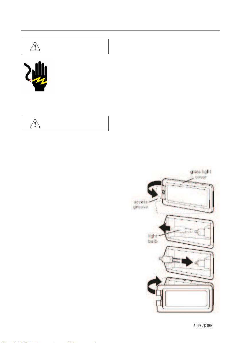
1. Unsnap glass light cover using a screwdriver in the
access groove.
2. Firmly grasp light bulb and pull out.
3. Replace with halogen bulb using volt and wattage
requirements listed on glass cover.
4. Replace the light cover by snapping glass cover onto
metal box.
5. Reconnect power at the mainfuse or circuit breaker.
54
|
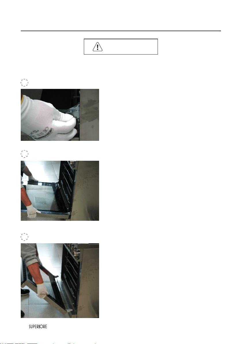
WARNING
TO PREVENT PERSONAL INJURY
Before removing the doors, make sure the pins are properly installed in the hinges. Failure to
do so can result in personal injury to hands and/or fingers.
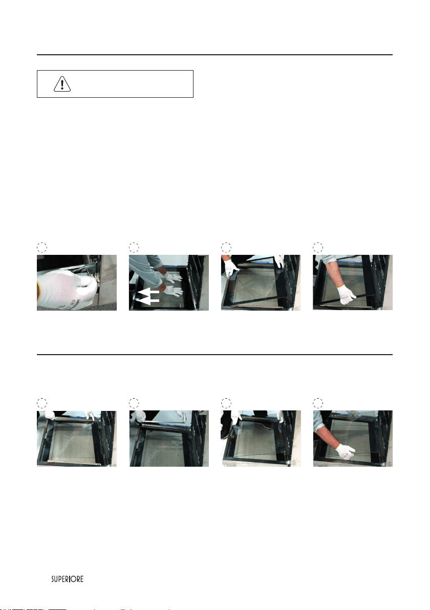
The door can be completely disassembled to guarantee the general cleaning, of the glasses and the other
parts. To disassembe the door you must observe the following procedure.
• Open the door and x the pin as indicated in picture 1.
• Put the hands on the internal glass surface, in the center, generate a small pressure and after slide back the
glass, as indicated in picture 2.
• Grasp the glass, rotate and remove as indicated in pictures 3 and 4.
• Grasp the bars and remove as indicated in pictures 5 and 6.
• Grasp the intermediate glass, rotate and remove as indicated in pictures 7 and 8.
Assamble again the door repeat all the operations but exactly one after the other in the
reverse sequence.
Before closing the door don’t forget to remove the pins.
1 32 4
5 76 8
Door Removal
Door Replacement and Adjustment
|
55
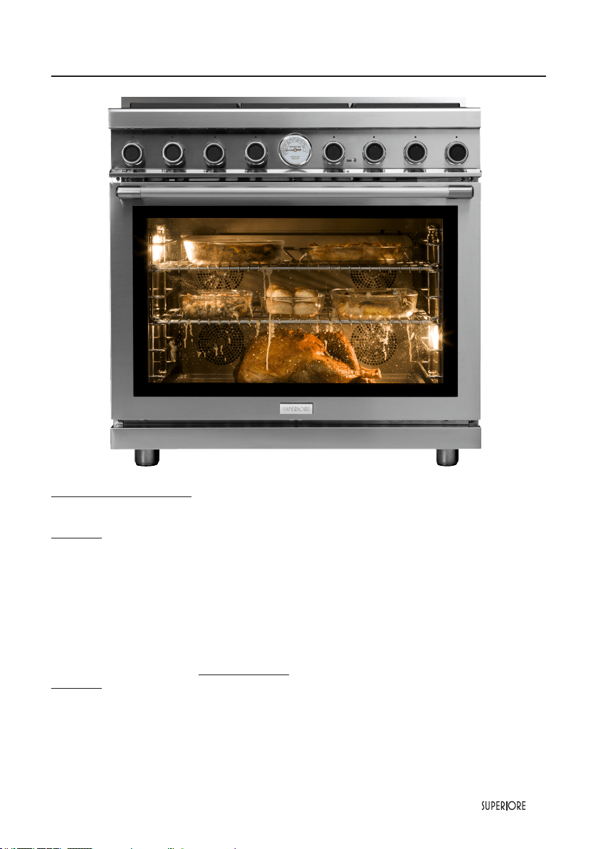
Thanksgiven dinner, SUPERIORE’s way
DAY BEFORE (if possible): PUMPKIN lling & STUFFING
PUMPKINPIE
Ingredients: 1 very large pumpkin or 2 small to medium-sized pumpkins (to make 2 pies) min. 5 - 7 lb.
Slice portion off top of pumpkin and save the “lid”. Remove the seeds and strings (all the pulp). Put entire
pumpkin in a pan, with the lid back on top, then pour a cup or two cups of water in pan.
Bake at 350° (180-190°) for about 1 to 1½ hours, depends on the size of the pumpkin. Using a fork to check,
cook until tender and falls apart. Remove from oven and either just pare -peel off skin- or cut pumpkin to
scrape out the insides. This should give you enough pumpkin for several pies. Then follow the recipe. You can
decide whether to make the pies the day before or not. Depends on time available and oven!
Follow instructions for Pumpkin Pie recipe.
BEGIN THE lst PART FOR THE GIBLET STUFFING for TURKEY
Ingredients: the innards from the turkey, 1 stalk celery, poultry seasoning or bouillon cube for poultry.
Simmer heart, liver, gizzard and neck in water
<
about 3 cups
>
with 1 stalk of celery and poultry seasoning
or bouillon cube for poultry. Simmer until tender, check with a fork. About 1 hour. Cool and chop (mince or
cube) into small pieces. Throw away celery. Keep liquid (broth) and meat in separate containers in refrigerator
until ready to prepare and add to Turkey the next day. Turkey is prepared on the morning or mid-morning
of Thanksgiving Day.
Follow instructions for Turkey preparation.

56
|
Thanksgiven dinner, SUPERIORE’s way
THANKSGIVING DAY:
2
nd
PART GIBLET STUFFING:
Ingredients: 1 box seasoned bread crumbs (12 cups croutons)
1 onion diced
2-3 celery stalks cut up
1 teaspoon of pepper
1 tablespoon of sage
1 tablespoon thyme
1 tablespoon poultry seasoning or bouillon cube for avor
broth from day before
innards/meat from day before
1 cup of butter
additional chicken broth and/or water (where necessary)
Remove the broth and meat that you prepared the day before from the refrigerator. In a pan, put enough butter
to lightly cook the onion almost sautéed, slight yellow color, stirring occasionally.
Then lower ame and stir in a portion of the bread crumbs, and a bit of broth, (note: stir to prevent excess
browning), then add more bread crumbs and broth, add in cut up celery stalks, sage, pepper, thyme and meat.
Remove from heat and mix lightly in a deep bowl. Mixture should just be damp/slightly wet, pliable. Set aside
unlil Turkey is ready to be stuffed.
ROASTING TURKEY
Ingredients: 10 - 12lb. Turkey (order in advance from favorite butcher)
a small amount of butter
salt and pepper
Giblet stufng
Preheat oven to 325-350° (170-180°). Clean the turkey. Then place a small amount of butter inside by trying
to coat the inside cavity. Then sprinkle cavity with a bit of salt and pepper. Stuff turkey in both cavities
........ main body and lower body area with the giblet stufng, close with either oven hooks, pins or cord.
Place turkey in already preheated oven. Cook at 325-350° (170-180°) for 4 to 5 hours. When turkey starts to
leave drippings, spoon or baste the liquid onto the turkey again, do this every 15-20 minutes until thoroughly
cooked.
MASHED POTATOES
Ingredients: 1-1½ potatoes per person (n. of guests X 1 or 1½)
milk
butter
salt (and pepper if desired)
Boil potatoes until tender. Drain and cool then peel. Smash potatoes, add in milk a pat of butter and salt.
Using blender, fork etc. until desired texture/consistency is obtained.
BROWN-SUGARED CARROTS
Ingredients: 1½ carrots per person
brown sugar
butter

|
57
Thanksgiven dinner, SUPERIORE’s way
Boil carrots until slightly tender. Drain, then remove and dice into circles. In a sauté pan melt butter and add
in diced carrots, sauté until more tender, add in brown sugar and if too dry add in a bit more butter and stir
and sauté until brown sugar is melted and coats the carrots.
PUMPKIN PIE (2 pies)
Ingredients: 1½ cups sugar
¼ tsp. salt
4 tsp. cinnamon
1 tsp. ginger
½ tsp. ground cloves
4 eggs (or 1 egg and 6 egg whites)
3½ cups pumpkin
3 cups evaporated milk
Combine sugar, salt, cinnamon, ginger and cloves in medium bowl. Beat eggs slightly in large bowl. Stir and
add in pumpkin and sugar and spice mixture from medium bowl. Mix well, then gradually add the evaporated
milk. Pour in to pie crust shells and Bake at 425° (220°) for 15 minutes, then lower oven temperature to
350° (180°). Bake for another 40 to 50 minutes or until point that when you insert a knife or toothpick in
the center of the pie, and pull it out it is clean. Cool on wire rack for 3 hours. Serve immediately or chill (do
not freeze). Serve with whipped cream.
APPLE PIE
Ingredients per pie: 7-8 apples (Granny Snith is best)
1 cup sugar
2 tbsp our
2 heaping tbsp. (3 cucc.) cinnamon
100 gr butter
Thinly slice apples. Mix sugar, our and cinnamon together in a large bowl. Add the apples to this and mix.
Place mixture in pie shell and then put small pieces of butter on top of mixture. Place top crust over this,
and join pieces, and cover edge with aluminum foil. Bake at 425° (220°) 25-30 minutes. Do not make slits
in top crust! As an extra: you can baste the top of the pies with a small amount of heated butter and then
sprinkle with sugar and cinnamon and place back in oven for the remaining time to nish baking. Serve hot
with vanilla ice-cream!
COUNTRY PAN GRAVY
Ingredients: drippings from turkey
¼ cup our
½ cup milk
salt and pepper
1 bouillon cube for poultry
Remove Turkey from pan. Place pan on stove with low heat. Mix our and milk with wire whip in deep
bowl. Slowly add this mixture to the drippings in the pan. Mixture should become thicker. If too thick, then
add more milk to pan gravy and crumble and add bouillon cube, salt and pepper to this. Serve over mashed
potatoes and stufng!

58
|
If service is required, call your dealer or authorized service agency.
The name of the authorized service agency can be obtained from the dealer or distributor in your area, or
calling 1-844-322-2111, for the USA, and 1-800-205-6450 for Canada.
Have the following information readily available.
• Model number
• Serial number
• Purchase date
• Name of dealership reference.
• Clearly describe the problem that you are having.
Record the information indicated below. You will need it if service is ever required.
The model and serial number can be found by looking in the last page of this booklet. A duplicate label is
located on the back side of the range.
Model no.
Serial no.
Date of purchase Date installed
Dealer’s name
Address
If service requires installation of parts, use only authorized parts to insure protection under warranty.
Keep this manual for future reference.
Service Information
|
59
Troubleshooting
Problem Possible Cause and /or Remedy
Range will not work.
Range is not connected to electrical power:
Have electrician check power circuit breaker,
wiring, and fuses.
Oven light will not work.
Light bulb is burned out.
Range is not connected to power.
Igniters will not work.
Circuit is tripped.
Fuse is blown.
Range is not connected to power.
Igniters sparking but no ame ignition. Gas supply is interrupted.
Igniters sparking continuously after ame ignition.
Power supply is not grounded.
Power supply polarity is reversed.
Igniters are wet or dirty.
Burner ignites but ame islarge, distorted, or yellow.
Burner ports are clogged.
Unit is being operated on wrong type of gas.
Air shutters not properly adjusted.
Strong odor and/or smoke is noticed
rst few times oven is used.
This is normal burn off of insulation and protecti-
ve oils in oven. This will go away after using oven
a few times.

60
|
Please record your model (MOD) and serial number (S/N) below for future reference. For your convenience,
a label containing this information is supplied with this booklet. When writing or calling about a service
problem, please include the following information:
- your name, address and telephone number
- appliance model and serial number
- name and address of your dealer
- a clear description of the problem you are having
- proof of purchase (sales receipt)
MOD:_______________________
S/N:________________________
SUPERIORE WARRANTY TWO YEARS PARTS AND LABOR
For two year from the date of the original purchase, SUPERIORE will repair or replace (at its option) any part
of the range which fails due to a defect in materials or workmanship. During this warranty, SUPERIORE will
provide, free of charge, all labor and in-home service to repair or replace the defective part. This warranty is
extended to the original purchaser and any succeeding owner with proper documentation of ownership for
products purchased for residential use within the United States of America.
EXCLUSIONS
This warranty does not cover any defect or damage, which is not direct fault of SUPERIORE; this includes,
but is not limited to:
1) Service trips to your home to instruct you how to use the product.
2) Service trips to your home, during which no fault is found.
3) Damages occurred during transit, handling and/or installation of the product.
4) Damages occurred in case the product has not been installed, duly following the manufacturer’s
installation instructions, as well as any local code or regulation.
5) Damages due to failure in following the manufacturer’s recommended care, cleaning and maintenance
instructions; in particular, damages to the oven and/or the worktop if they have not been cared and
cleaned according to these instructions.
6) Any repair, modication, alteration, or adjustment provided by any person not authorized by SUPERIORE.
7) Failure of the product if it is abused, misused or used for other than the intended purpose or if used
commercially/industrially.
8) Incorrect electric current, voltage or power supply.
9) Improper setting of any control.
10) Replacement of house fuses or resetting of circuit breakers.
11) Replacement of the light bulbs.
12) Wear and tear
13) Any substance, accumulating in any part or component of the product.
14) Damages to anything situated next to the product, including, but not limited to, ceiling, oor or cabinetry.
15) Damage to the product caused by accident, re, oods or acts of God.
16) Expenses for travel and transportation to locations more than 30 miles from an authorized SUPERIORE
retailer.
17) Products with original serial numbers that have been removed.
The remedies described above are the only ones which SUPERIORE will provide, either under this
warranty or under any warranty arising by operation of law. SUPERIORE will not be responsible for any
consequential or incidental damages arising from the breach of this warranty or any other warranty,
whether express, implied or statutory.
Some States do not allow the exclusion or limitation of incidental or consequential damages. This
warranty gives you specic legal rights, and you may also have other rights which vary from state to
state. To know what your legal rights are, consult your local state consumer affairs ofce or your state’s
Attorney General.
WARRANTY U.S.A & CANADA
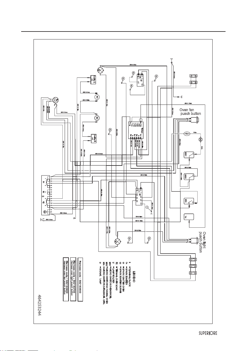
|
61
Electric diagram 30” and 36”ranges

62
|

TECNO, S.P. 63R n. 111, 42044 Gualtieri (RE), Italy
T. +39 0522 222 161
appliances are proudly designed and handcrafted in Gualtieri, Italy
Tecnogas, Tecnogas SUPERIORE and SUPERIORE are registered trademarks of TECNO

superiore.us
superiore.ca
461308640 - 02/2018