customer service
1.888.880.8368
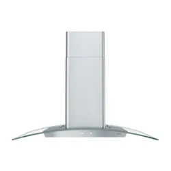
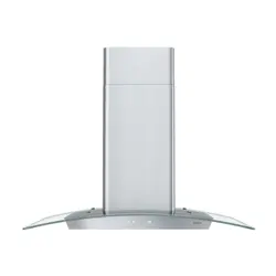
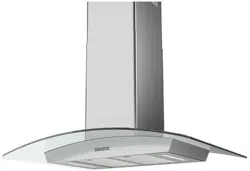
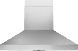
Duct Cover Extension
Z1C-00VL
For use with Vista Island range hood
ENGLISH..........................2
FRANÇAIS........................4
Mounting the duct cover
Fixation des cheminees

Installation - Mounting the Duct Cover
MOUNTING THE DUCT COVER
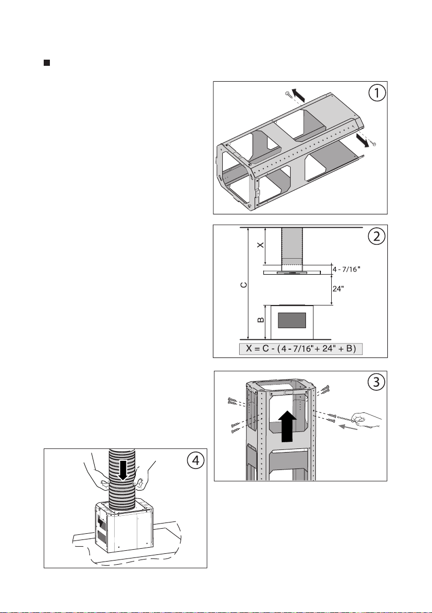
1. Remove the (2) screws to un-
lock the top support frame from
the bottom support frame. Fig.1.
Adjust the height by referring to
the diagram in Fig. 2. Secure the
support frames together with (2)
screws per extension arm (Tot. 8).
Fig.3
2. Place correct size ducting for your
installation (not supplied) on top
of hood and secure to the blower
collar with aluminum duct tape.
The ducting should be long enou-
gh so it protrudes out the top of
the support frame and extends
into the attic to connect after the
hood is installed. Fig.4
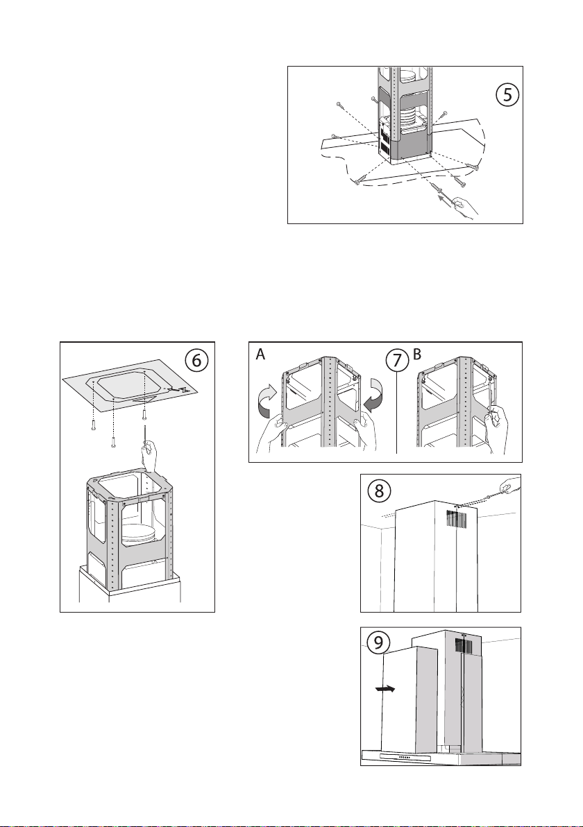
3. Place assembled support frames
on top of hood and secure it to the
hood body using 8 screws. Fig.5
4. Position hole template on the cei-
ling paying attention that the ar-
row is positioned on the same side
as the range hood controls. Fig.6
- 2 -
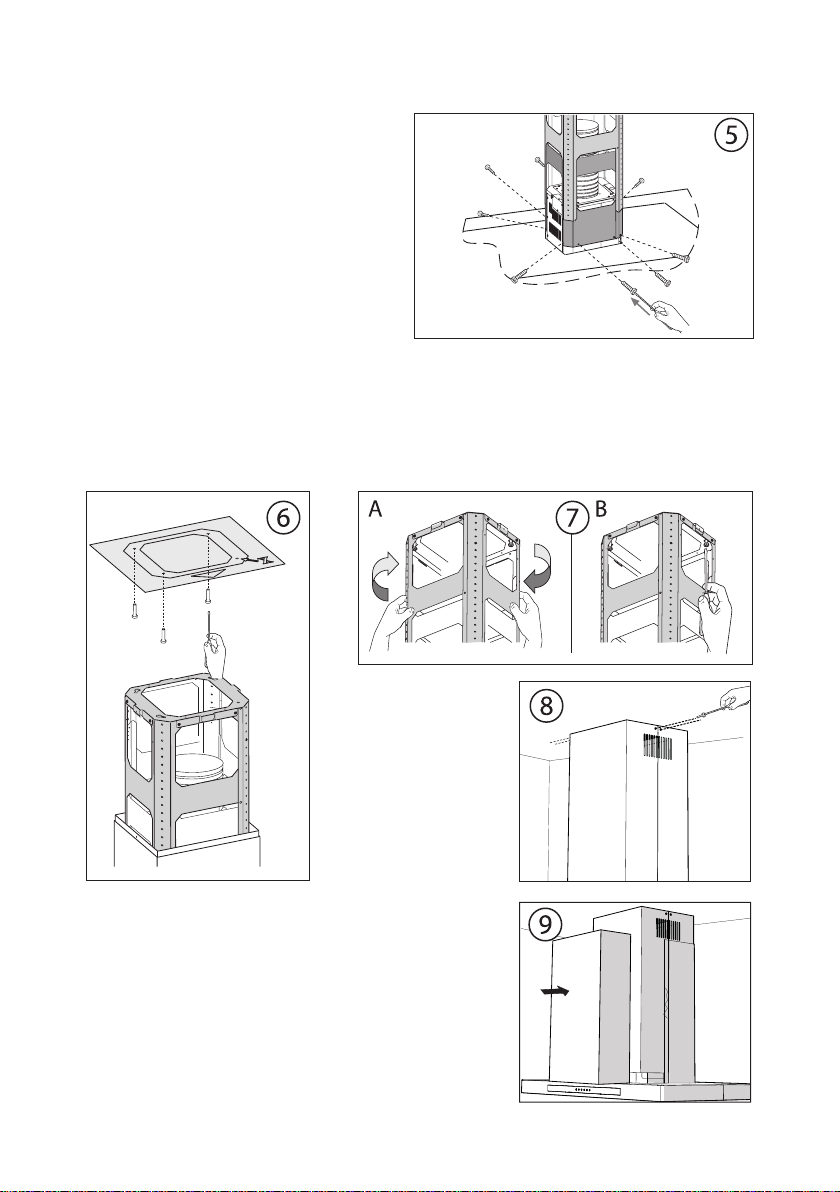
- Make 4, holes in the ceiling and drive in
(3) screws without completely tighte-
ning them. Pay attention not to insert
the screw into the hole marked with
an X on the hole template.
6. Lift the hood assembly to the cei-
ling and align the top support fra-
me with the (3) screws previously
installed in the ceiling.
- Rotate assembly slightly clockwise to lock in place. Fig.7A. Drive in the fourth
screw and tighten the remaining 3 screws to secure the structure in place.
Fig.7B
7. Secure the two
upper duct covers
to support frame
with (4) screws. Fig.8
8. Secure the two
lower duct covers
parts to the support frame by overlapping the
lateral magnets. Fig.9
9. Verify that ducting from hood is connected to
ducting in the attic that will exhaust air out of
the home.
- 3 -
Installation – Fixation De Cheminees
FIXATION DES CHEMINEES
1. Enlevez les (2) vis pour séparer
la partie supérieure de la partie
inférieure. Fig. 1. Régler la hauteur
désirée en se référant aux cotes
indiquées dans la (fig. 2) et la blo-
quer au moyen des (2 ) vis fournies
avec l’appareil. (Tot. 8 )Fig.3
2. Positionnez le conduit (non fourni)
proportionné à l’installation sur la
partie supérieure de la hotte et fi-
xez-le au collier du reniflard en uti-
lisant le ruban aluminium spécial.
Le conduit doit être assez long
pour sortir de la partie supérieure
du cadre de support et pour s’éten-
dre jusqu’à l’intérieur du grenier. Le
conduit sera relié une fois la hotte
installée. Fig. 4
3. Positionnez le cadre de support in-
stallé sur la partie supérieure de la
hotte et fixez-le au corps de la hot-
te à l’aide des 8 vis (fig. 5).
4. Positionner le gabarit de forure au
plafond en faisant attention à ce que la
flèche soit positionnée du même côté
que la commande de l’appareil. Fig.6
- 4 -
- Effectuer les 4 trous au plafond et
visser (3) vis sans les serrer com-
plètement et en prenant garde de
ne pas insérer la vis dans le trou
marqué par un X sur le gabarit de
forure.
6. Soulevez la hotte vers le haut et
procédez à l’alignement du cadre
de support supérieur avec les (3)
vis précédemment fixées au pla-
fond.
- Faire une petite rotation pour l’encastrement. Fig. 7A. Visser la quatrième vis X
et serrer les 3 autres qui restent pour permettre le blocage définitif de la partie
supérieure de la structure. Fig. 7B
7. Fixez les 2 con-
duits décoratifs à
la structure de sup-
port au moyen de
(4) vis d’assembla-
ge. Fig.8
8. Fixer les deux
conduit décoratif
inférieure sur la structur de support en faisant
se chevaucher les aimants latéraux. Fig.9
9. Vérifiez que le conduit sortant de la hotte est
bien relié au conduit du grenier pour l’évacua-
tion extérieure.
- 5 -
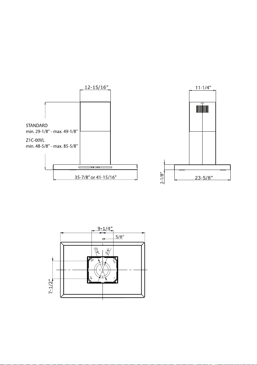
DUCT COVER EXTENSION SPECIFICATION
= =
- 6 -
- 7 -

3011000133700.00