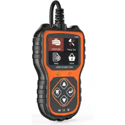
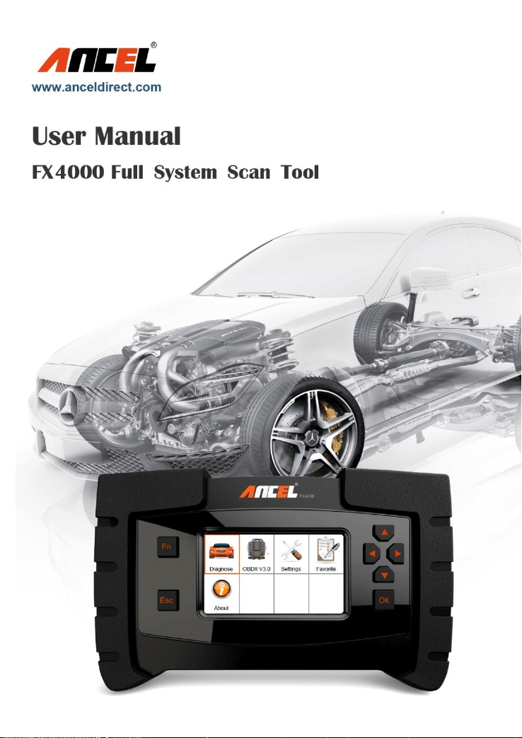

FX4000 Full System Scan Tool
Table of Contents
1. SAFETY PRECAUTIONS AND WARNINGS ............... 4
2. GENERAL INFORMATION ........................................... 5
2.1 ON-BOARD DIAGNOSTICS (OBD) II .............................. 5
2.2 DIAGNOSTIC TROUBLE CODES (DTCS) ........................ 5
2.3 LOCATION OF DATA LINK CONNECTOR (DLC) .............. 7
2.4 OBD II READINESS MONITORS ..................................... 8
2.5 OBD II MONITOR READINESS STATUS .......................... 9
2.6 OBD II DEFINITIONS .................................................... 10
3. USING THE SCAN TOOL ........................................... 13
3.1 TOOL DESCRIPTION ..................................................... 13
3.2 SPECIFICATIONS .......................................................... 13
3.3 ACCESSORIES INCLUDED ............................................ 14
3.4 KEYBOARD ................................................................... 14
Function Button ........................................................... 14
3.4.1 To set favorite car makes ..................................... 14
3.4.2 To select live data at the actual value testing .... 15
3.4.3 Used as Tab button at special function .............. 15
3.4.4 To load the keyboard for message input ............ 16
Esc Button .................................................................... 17
Up Button ...................................................................... 17
Down Button ................................................................. 17
Left Button .................................................................... 17
Right Button ................................................................. 18
OK Button ..................................................................... 18
3.5 POWER SUPPLY ........................................................... 18
3.6 DIAGNOSE .................................................................... 19
American coverage ..................................................... 19
European coverage ..................................................... 20
Asian coverage ............................................................ 21
3.7 FAVORITE ..................................................................... 22
3.8 OBDII .......................................................................... 22

FX4000 Full System Scan Tool
3.9 SETTINGS ..................................................................... 23
Language ...................................................................... 24
Unit ................................................................................. 25
Beep ............................................................................... 26
Key Test ......................................................................... 27
LCD Test ........................................................................ 28
3.10 ABOUT ........................................................................ 28
3.11 VEHICLE COVERAGE .................................................. 29
3.12 PRODUCT TROUBLESHOOTING .................................. 29
Vehicle Linking Error .................................................... 29
Operating Error ............................................................. 30
Scan tool doesn’t power up ........................................ 30
4. DIAGNOSTIC OPERATIONS ...................................... 31
4.1 START A NEW TEST ...................................................... 31
4.2 START A QUICK TEST .................................................... 34
4.3 READ IDENTIFICATION .................................................. 39
4.4 READ FAULT MEMORY / READ DTC .............................. 40
4.5 CLEAR FAULT MEMORY / CLEAR DTC .......................... 41
4.6 READ LIVE DATA / DATASTREAM ................................... 43
5. SOFTWARE UPDATE .................................................. 46
5.1 REGISTER THE SCAN TOOL ........................................... 46
5.2 SOFTWARE UPDATE FLOW CHART .............................. 47
6. WARRANTY AND SERVICE ....................................... 48
6.1 LIMITED ONE YEAR WARRANTY ................................... 48
6.2 SERVICE PROCEDURES ................................................ 50
FAQ (FREQUENCY ASK QUESTIONS) ........................ 50

FX4000 Full System Scan Tool
1. Safety Precautions and Warnings
To prevent personal injury or damage to vehicles
and/or the scan tool, read this instruction manual first
and observe the following safety precautions at a
minimum whenever working on a vehicle:
Always perform automotive testing in a safe
environment.
Wear safety eye protection that meets ANSI
standards.
Keep clothing, hair, hands, tools, test equipment, etc.
away from all moving or hot engine parts.
Operate the vehicle in a well-ventilated work area:
Exhaust gases are poisonous.
Put blocks in front of the drive wheels and never
leave the vehicle unattended while running tests.
Use extreme caution when working around the
ignition coil, distributor cap, ignition wires and spark
plugs. These components create hazardous voltages
when the engine is running.
Put the transmission in PARK (for automatic
transmission) or NEUTRAL (for manual transmission)
and make sure the parking brake is engaged.
Keep a fire extinguisher suitable for
gasoline/chemical/ electrical fires nearby.
Don’t connect or disconnect any test equipment
while the ignition is on or the engine is running.
Keep the scan tool dry, clean, free from oil/water or
grease. Use a mild detergent on a clean cloth to
clean the outside of the scan tool, when necessary.

FX4000 Full System Scan Tool
2. General Information
2.1 On-Board Diagnostics (OBD) II
The first generation of On-Board Diagnostics (OBD I) was
developed by the California Air Resources Board (ARB)
and implemented in 1988 to monitor some of the emission
control components on vehicles. As technology evolved
and the desire to improve the On-Board Diagnostic
system increased, a new generation of On-Board
Diagnostic system was developed. This second
generation of On-Board Diagnostic regulations is called
"OBD II".
The OBD II system is designed to monitor emission
control systems and key engine components by
performing either continuous or periodic tests of specific
components and vehicle conditions. When a problem is
detected, the OBD II system turns on a warning lamp (MIL)
on the vehicle instrument panel to alert the driver typically
by “Check Engine” or “Service Engine Soon”.
The system will also store important information about the
detected malfunction so that a technician can accurately
find and fix the problem.
Here below three pieces of such valuable information:
1) Malfunction Indicator Light (MIL) is commanded as 'ON'
or 'OFF';
2) Diagnostic Trouble Codes (DTCs) are stored;
3) Readiness Monitor status.
2.2 Diagnostic Trouble Codes (DTCs)
OBD II Diagnostic Trouble Codes are codes that are
stored by the on-board computer diagnostic system in
response to a problem found in the vehicle. These codes
identify a particular problem area and are intended to

FX4000 Full System Scan Tool
provide you with a guide as to where a fault might be
occurring within a vehicle. OBD II Diagnostic Trouble
Codes consists of a five-digit alphanumeric code. The first
character, a letter, identifies which control system sets the
code. The other four characters, all numbers, provide
additional information on where the DTC originated and
the operating conditions that caused it to set. Here below
is an example to illustrate the structure of the digits:
Explanation of OBD2 Diagnostic Trouble Codes
X X X X X
Fault Description
1- Fuel & Air Metering
2- Fuel & Air Metering (Injector circuit)
3- Ignition System of Misfire
4- Auxiliary Emission Controls
5- Vehicle Speed Control & Idle Control System
6 - Computer Output Circuit
7,8,9- Transmission (Gearbox)
A,B.C- For Hybrid Propulsion
0- Generic OBD Code
1- Vehicle Manufacturer Specific Code
B- Body (Includes A/C & Air Bag)
C- Chassis (Includes ABS)
P- Powertrain (Engine & Transmission/Gearbox)
U- User Network (Wiring Bus/UART)
FX4000 Full System Scan Tool
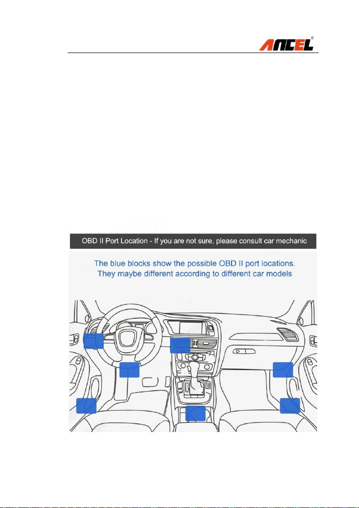
2.3 Location of Data Link Connector (DLC)
The DLC (Data Link Connector or Diagnostic Link
Connector) is the standardized 16-cavity connector where
diagnostic scan tools interface with the vehicle's on-board
computer. The DLC is usually located 12 inches from the
center of the instrument panel (dash), under or around the
driver’s side for most vehicles.
If Data Link Connector is not located under dashboard, a
label should be there telling location. For some Asian and
European vehicles, the DLC is located behind the ashtray
and the ashtray must be removed to access the connector.
If the DLC cannot be found, refer to the vehicle’s service
manual for the location.

FX4000 Full System Scan Tool
2.4 OBD II Readiness Monitors
An important part of a vehicle’s OBD II system is the
Readiness Monitors, which are indicators used to find out
if all of the emissions components have been evaluated
by the OBD II system. They are running periodic tests on
specific systems and components to ensure that they are
performing within allowable limits.
Currently, there are eleven OBD II Readiness Monitors
(or I/M Monitors) defined by the U.S. Environmental
Protection Agency (EPA). Not all monitors are supported
by all vehicles and the exact number of monitors in any
vehicle depends on the motor vehicle manufacturer’s
emissions control strategy.
Continuous Monitors -- Some of the vehicle
components or systems are continuously tested by the
vehicle’s OBD II system, while others are tested only
under specific vehicle operating conditions. The
continuously monitored components listed below are
always ready:
Misfire
Fuel System
Comprehensive Components (CCM)
Once the vehicle is running, the OBD II system is
continuously checking the above components, monitoring
key engine sensors, watching for engine misfire, and
monitoring fuel demands.
Non-Continuous Monitors -- Unlike the continuous
monitors, many emissions and engine system
components require the vehicle to be operated under
specific conditions before the monitor is ready.

FX4000 Full System Scan Tool
These monitors are termed non-continuous monitors.
For different ignition type engines, the available monitors
are different too.
The following monitors are to be used for spark ignition
engines only:
EGR System
O2 Sensors
Catalyst
Evaporative System
O2 Sensor Heater
Secondary air
Heated Catalyst
The following monitors are to be used for compression
ignition engines only:
EGR System
NMHC Catalyst
NOx after treatment
Boost pressure system
Exhaust gas sensor
PM filter
2.5 OBD II Monitor Readiness Status
OBD II systems must indicate whether or not the vehicle’s
PCM’s monitor system has completed testing on each
component. Components that have been tested will be
reported as “Ready”, or “Complete”, meaning they have
been tested by the OBD II system.
The purpose of recording readiness status is to allow
inspectors to determine if the vehicle’s OBD II system has
tested all the components and/or systems.

FX4000 Full System Scan Tool
The power-train control module (PCM) sets a monitor to
“Ready” or “Complete” after an appropriate drive cycle
has been performed. The drive cycle that enables a
monitor and sets readiness codes to “Ready” varies for
each individual monitor.
Once a monitor is set as “Ready” or “Complete”, it will
remain in this state. A number of factors, including erasing
of diagnostic trouble codes (DTCs) with a scan tool or a
disconnected battery, can result in Readiness Monitors
being set to “Not Ready”.
Since the three continuous monitors are constantly
evaluating, they will be reported as “Ready” all of the time.
If testing of a particular supported non-continuous monitor
has not been completed, the monitor status will be
reported as “Not Complete” or “Not Ready.”
In order for the OBD monitor system to become ready, the
vehicle should be driven under a variety of normal
operating conditions. These operating conditions may
include a mix of highway driving and stop and go, city type
driving, and at least one overnight-off period. For specific
information on getting your vehicle’s OBD monitor system
ready, please consult your vehicle owner’s manual.
2.6 OBD II Definitions
Power-train Control Module (PCM) -- OBD II
terminology for the on-board computer that controls
engine and drive train.
Malfunction Indicator Light (MIL) -- Malfunction
Indicator Light (Service Engine Soon, Check Engine) is a
term used for the light on the instrument panel. It is to
alert the driver and/or the repair technician that there is a

FX4000 Full System Scan Tool
problem with one or more of vehicle's systems and may
cause emissions to exceed federal standards. If the MIL
illuminates with a steady light, it indicates that a problem
has been detected and the vehicle should be serviced as
soon as possible. Under certain conditions, the
dashboard light will blink or flash. This indicates a severe
problem and flashing is intended to discourage vehicle
operation. The vehicle onboard diagnostic system cannot
turn the MIL off until necessary repairs are completed or
the condition no longer exists.
DTC -- Diagnostic Trouble Codes (DTC) that identifies
which section of the emission control system has
malfunctioned.
Enabling Criteria -- Also termed Enabling Conditions.
They are the vehicle-specific events or conditions that
must occur within the engine before the various monitors
will set, or run. Some monitors require the vehicle to
follow a prescribed “drive cycle” routine as part of the
enabling criteria. Drive cycles vary among vehicles and
for each monitor in any particular vehicle.
OBD II Drive Cycle -- A specific mode of vehicle
operation that provides conditions required to set all the
readiness monitors applicable to the vehicle to the “ready”
condition. The purpose of completing an OBD II drive
cycle is to force the vehicle to run its onboard diagnostics.
Some form of a drive cycle needs to be performed after
DTCs have been erased from the PCM’s memory or after
the battery has been disconnected. Running through a
vehicle’s complete drive cycle will “set” the readiness
monitors so that future faults can be detected. Drive
cycles vary depending on the vehicle and the monitor that

FX4000 Full System Scan Tool
needs to be reset. For vehicle specific drive cycle, consult
the vehicle’s Owner’s Manual.
Freeze Frame Data -- When an emissions related fault
occurs, the OBD II system not only sets a code but also
records a snapshot of the vehicle operating parameters to
help in identifying the problem. This set of values is
referred to as Freeze Frame Data and may include
important engine parameters such as engine RPM,
vehicle speed, air flow, engine load, fuel pressure, fuel
trim value, engine coolant temperature, ignition timing
advance, or closed loop status.
FX4000 Full System Scan Tool
3. Using the Scan Tool
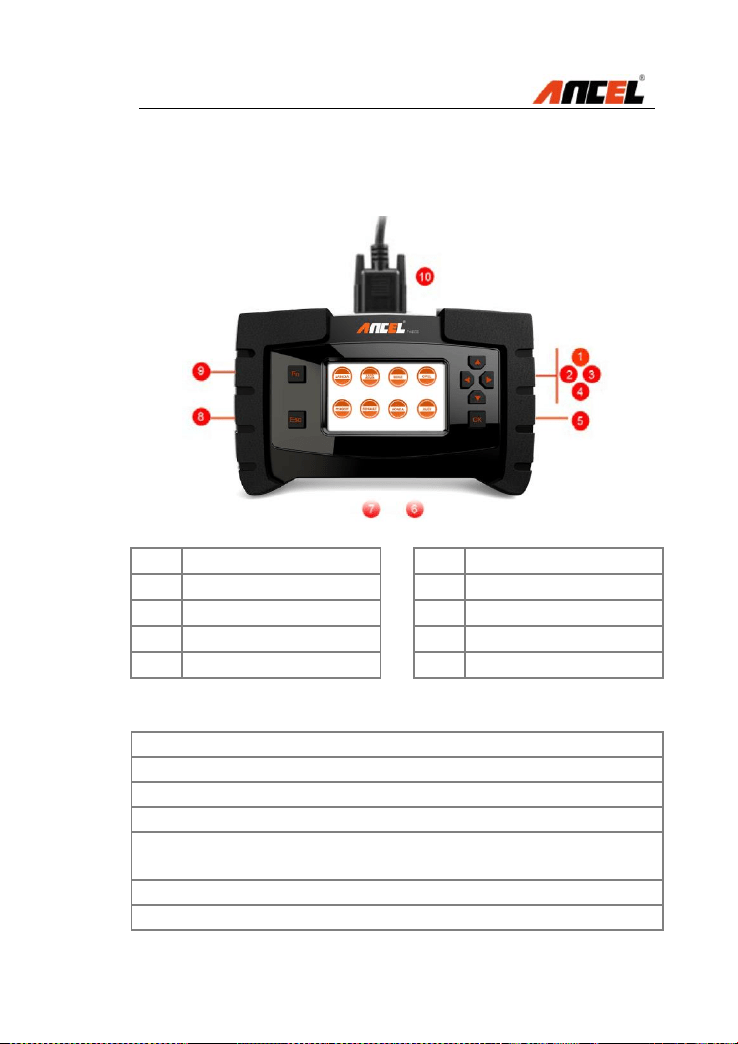
3.1 Tool Description
1
Up button
6
Power Supply Port
2
Left button
7
USB Port
3
Right button
8
Esc button
4
Down button
9
Function button
5
OK button
10
Main cable port
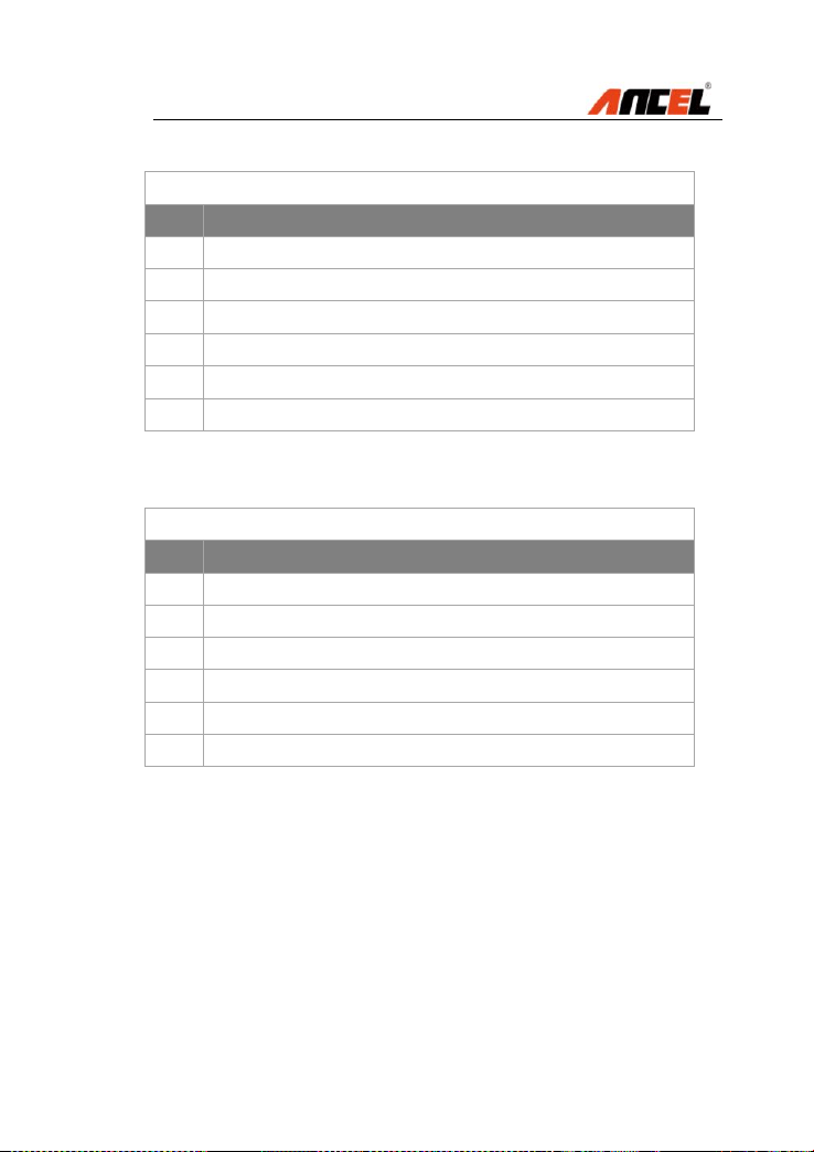
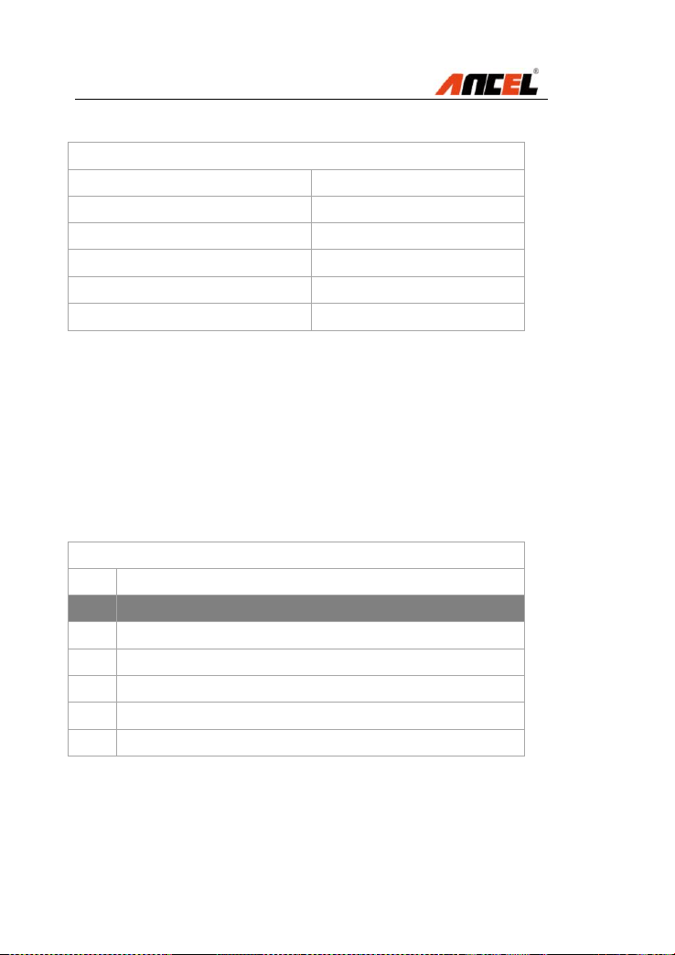
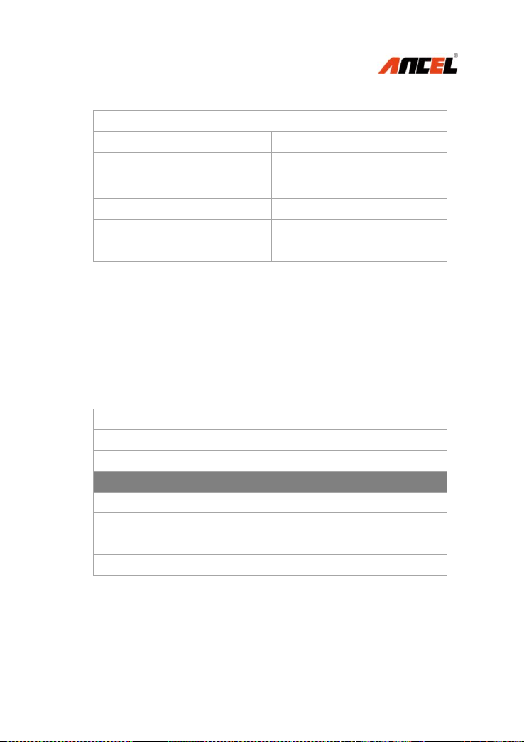
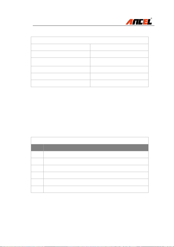
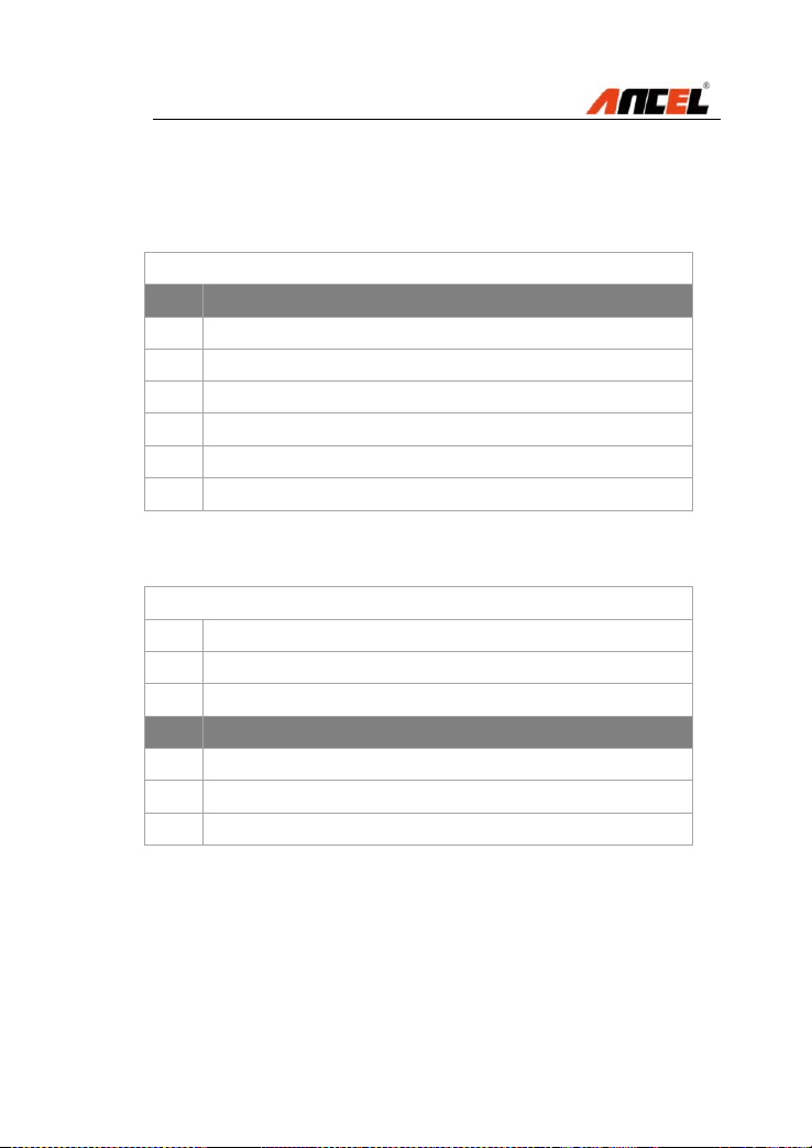
3.2 Specifications
No
Item
Description
1
Display
TFT color display(480 x 272 dpi)
2
Working Temp
-20 to 60°C (32 to 140 °F)
3
Storage Temp.
-20 to 70°C (-4 to 158 °F)
4
Power Supply:
12 - 18V power provided
via vehicle battery or adapter
5
Dimensions
L: 270 mm W: 250mm H:75mm
6
Gross Weight
1.5kg

FX4000 Full System Scan Tool
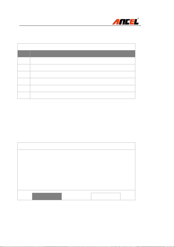
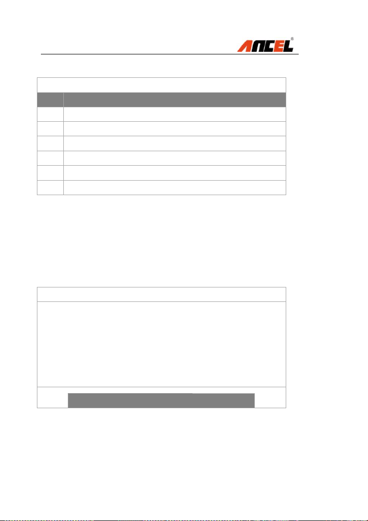
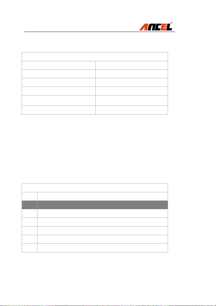
3.3 Accessories Included
No
Item
Description
1
User Manual
Instructions for tool operations
2
Main cable
Connect the tool and the OBDII
connector to the vehicle
3
OBDII
connector
Provide the power supply and
communicates between tool and
vehicle
4
USB cable
Used to upgrade the software for
the scan tool
5
Carry case:
A portable case to store the scan
tool when not in use
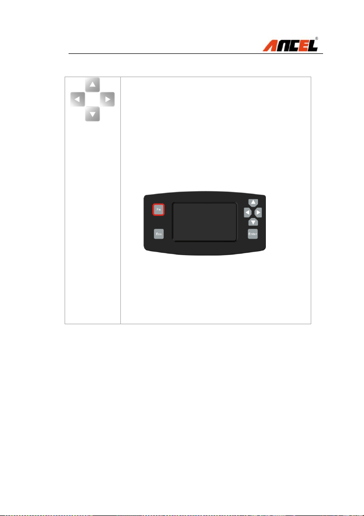
3.4 Keyboard
Function Button
Function Button - Corresponds with “Fn” on screen for
executing commands
There are several functions for Fn button as below:
3.4.1 To set favorite car makes
How to do:.
Diagnose --- OK --- American --- OK --- Fn --- GM
A green cross will be popup on the right corner of the
vehicle icon.
Note:
Move Left and Right button to set favorite car makes
Click Fn again to cancel favorite car makes settings

FX4000 Full System Scan Tool
3.4.2 To select live data at the actual value testing
How to do:
Diagnose --- OK --- EUROPEAN --- BENZ --- OK ---
Down Button --- [2] Transport or V-Class --- OK --- [1]
Sprinter --- OK --- [1] 906 --- OK --- [1] Gasoline engine
--- OK --- [1] Left-hand steering --- OK --- [1] Manual
transmission --- OK --- [2] Control units --- [1] Drive ---
OK --- [1] ETC --- Electronic transmission control ---
OK --- Down Button --- [5] Actual values --- [1] Speeds
--- OK --- Fn Button --- [1] 001 Y33/6n2 (speed sensor
A red cross will be popup on the left of the live data
Note:
Move Up and Down to select more items
Move Left and Right for page up and page down
Only live data can be selected for graphic display
3.4.3 Used as Tab button at special function
How to do:
Diagnose --- OK --- EUROPEAN --- BENZ --- OK
--- Down Button --- [2] Transport or V-Class ---
OK --- [1] Sprinter --- OK --- [1] 906 --- OK --- [1]
Gasoline engine --- OK --- [1] Left-hand steering
--- OK --- [1] Manual transmission --- OK --- [2]
Control units --- [1] Drive --- OK --- [1] ETC ---
Electronic transmission control --- OK --- Down
Button --- [6] Actuations --- OK --- [1] Test all
solenoid valves --- OK --- OK
FX4000 Full System Scan Tool
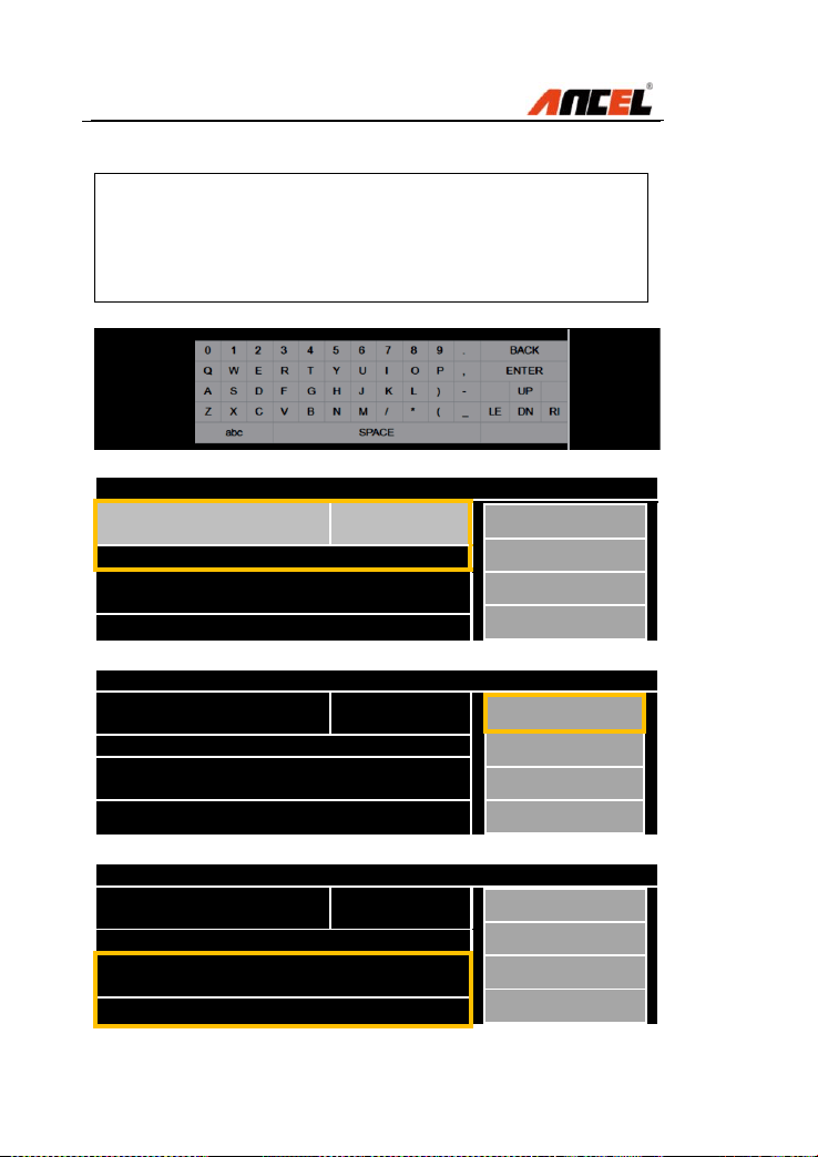
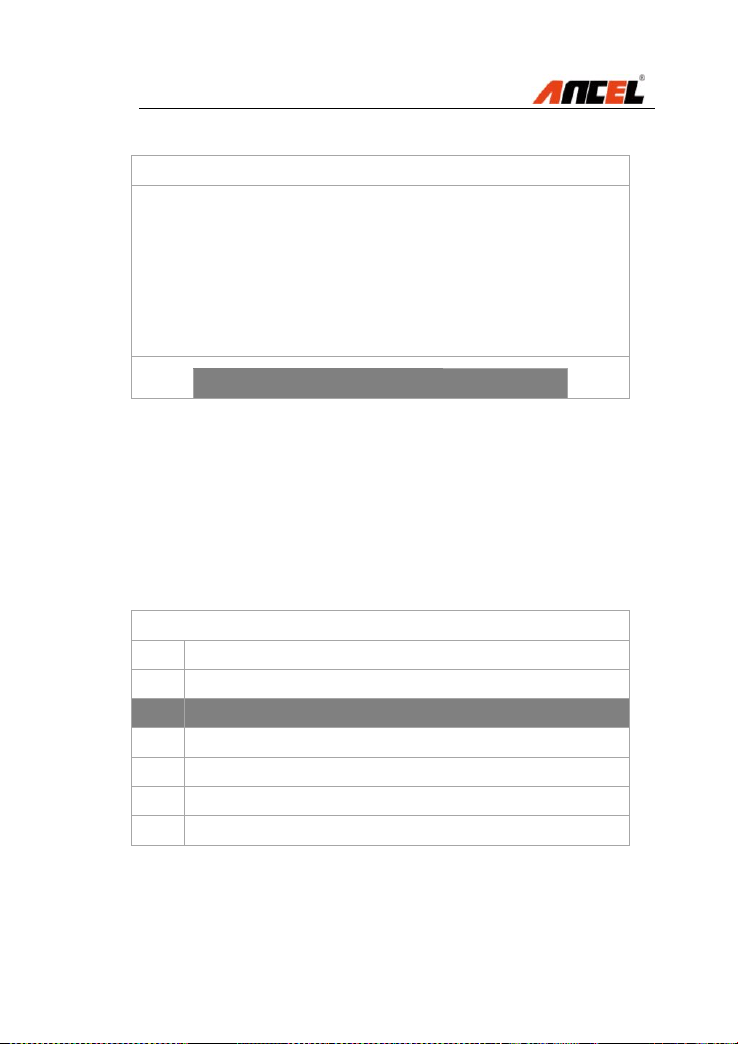
3.4.4 To load the keyboard for message input
How to do:
Diagnose --- OK --- EUROPEAN --- VW --- Live
Data --- Input Chanel Number
Test all solenoid valves
011 Selected gear by
means of selector lever
D
F1
Function Button Description
F1: START
Press “Fn” to operate other modules
Test all solenoid valves
011 Selected gear by
means of selector lever
D
F1
Function Button Description
F1: START
Press “Fn” to operate other modules
Test all solenoid valves
011 Selected gear by
means of selector lever
D
F1
Function Button Description
F1: START
Press “Fn” to operate other modules

FX4000 Full System Scan Tool
A red cross will be popup on the left of the live data
Three conditions are shown as below when click the Fn
button, in this case the Up, Down, Left, Right and OK
buttons will be activated accordingly:
Note:
Move Up and Down to select more items
Move Left and Right for page up and page down
Only live data can be selected for graphic display
Esc Button
Esc Button - Cancels a selection (or action) from a menu
or returns to the previous screen
Up Button
Up Button - Moves up through menu and submenu items
in menu mode. When more than one screen of data is
retrieved, moves up through the current screen to the
previous screens for additional data. When looking up
DTC, it is used to change value of selected character
Down Button
Down Button -Moves down through menu and submenu
items in menu mode. When more than one screen of data
is retrieved, moves down through the current screen to
next screens for additional data. When looking up DTC, it
is used to change value of selected character
Left Button
Left Button - When look up DTC definitions, moves to
previous character and views additional information on
previous screens if DTC definition covers more than one
screen; views previous screen /frames of recorded data.

FX4000 Full System Scan Tool
Right Button
Right Button -When look up DTC definitions, moves to
next character and view additional information on next
screens if DTC definition covers more than one screen;
views next screen or next frames of recorded data.. It is
also used to view next trouble code when viewing DTCs.
OK Button
OK Button - Confirms a selection /action from a menu.
3.5 Power Supply
Before using the scan tool, you must provide power to the
scan tool. There are two methods for providing power to
the scan tool.
DC external power adapter.
Cable connection to vehicle.
During vehicle testing, power for the scan tool is usually
provided through the vehicle cable connection. When the
scan tool is not connected to a vehicle, the scan tool can
be powered with an AC/DC external power adapter.
While the scan tool is powered via the vehicle Data Link
Connector (DLC), just follow the steps below to turn on
the scan tool:
1) Connect the Cable to scan tool.
2) Find DLC on vehicle.
NOTE: The DLC cover may be found for some vehicles
and you need to remove the plastic cover before plugging
the OBDII connector.
3) Plug the OBDII connector to the vehicle’s DLC.
4) Power up the tool, and wait for the Main Screen.
FX4000 Full System Scan Tool
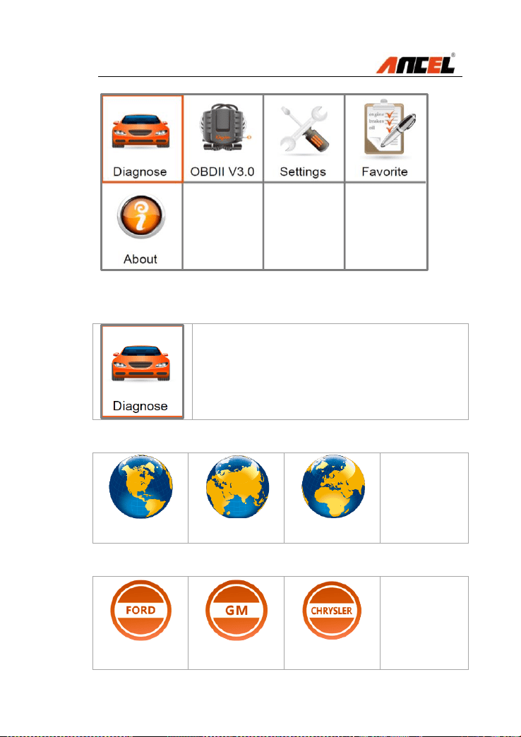
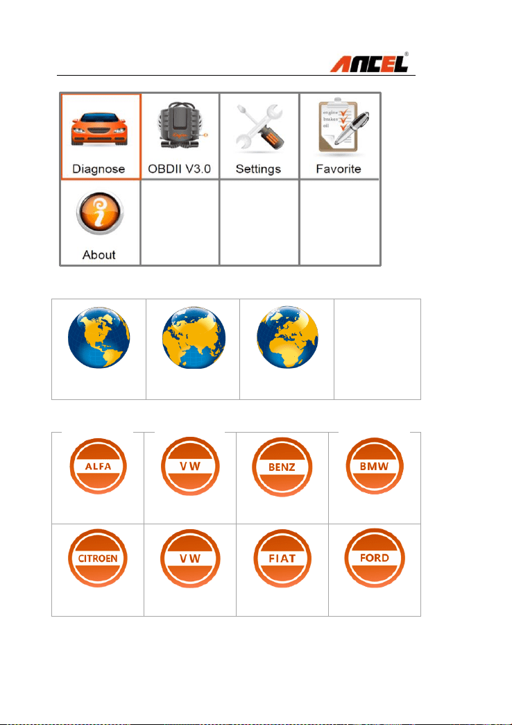
3.6 Diagnose
This section provides the car diagnosis
base on different areas and car makes.
Three options are available for area choices as below:
AMERICAN
ASIAN
EUROPEAN
American coverage
FORD
GM
CHRYSLER
FX4000 Full System Scan Tool
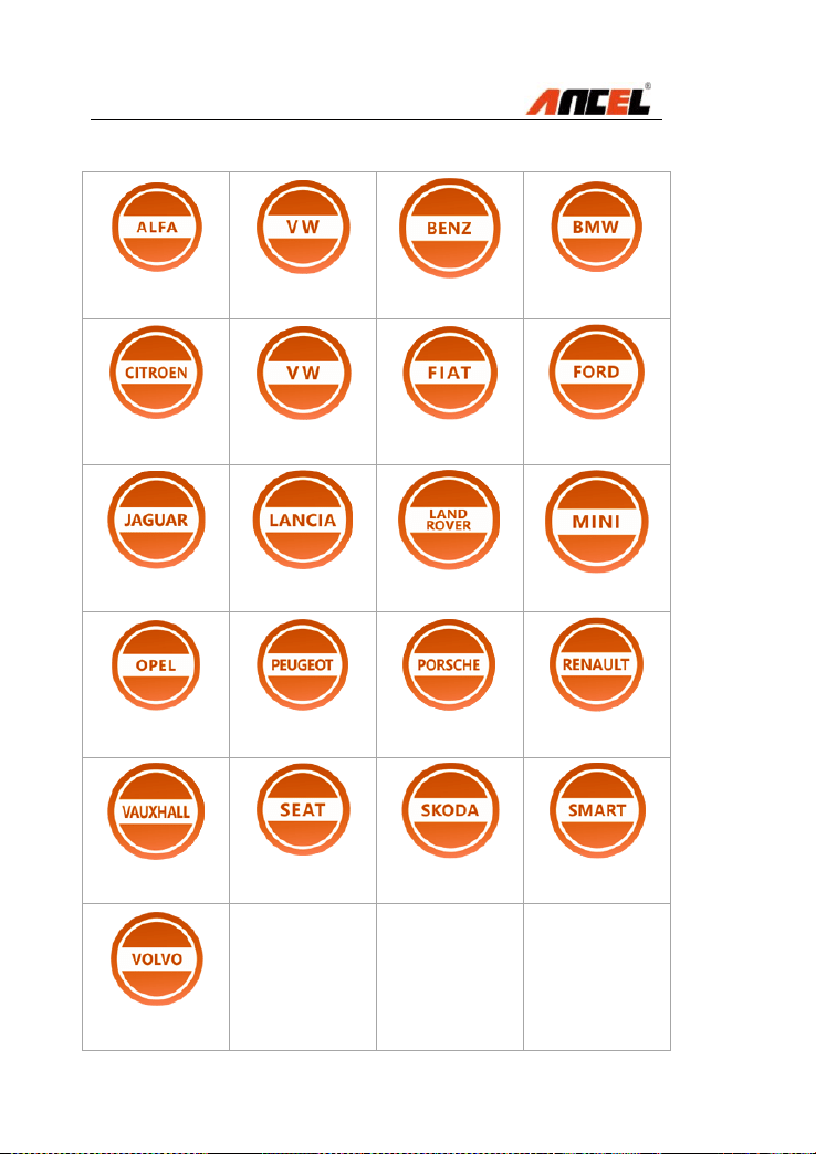
European coverage
ALFA-ROMEO
AUDI
BENZ
BMW
CITROEN
VOLKSWAGEN
FIAT
FORD
JAGUAR
LANCIA
LANDROVER
MINI
OPEL
PEUGEOT
PORSCHE
RENAULT
VAUXHALL
SEAT
SKODA
SMART
VOLVO

FX4000 Full System Scan Tool
Asian coverage
ACURA
DAEWOO
DAIHATSU
TOYOTA
HONDA
HYUNDAI
INFINITI
ISUZU
KIA
LEXUS
MAZDA
MITSUBISHI
NISSAN
SSANGYONG
SUBARU
SUZUKI
FX4000 Full System Scan Tool
3.7 Favorite
This section provides user customizing
car makes adding function.
How to do:
1) Move the Left/Right or Up/Down
button under the Main Menu to select
the button Diagnose.
2) Press OK, and then select some
area from American, Asian and
European. The screen will display
different car makes in list.
3) Press Fn, a green mark will be
displayed on the upper right corner
of the car make icon.
4) Press OK to save the setting. Any
car icons can be added and saved as
the Favorite by this way.
5) The user can access Favorite for car
testing which is common used.
3.8 OBDII
This section provides OBD protocols for vehicle
communication including:
SAE J1850-41.6 Kbps (PWM)
SAE J1850-10.4 Kbps (VPW)"
ISO 14230 (KWP2000)"
ISO 9141-2"
ISO 15765 (CAN)"
FX4000 Full System Scan Tool
3.9 Settings
This section provides system setting
functions for the scan tool.
Five options are available for area choices as below:
LANGUAGE
UNIT
BEEP
KEY TEST
LCD TEST
To enter the Settings menu
From the Main Screen, use Left/Right to select Settings,
and press OK.
Following the instructions to do adjustments and settings
could make your diagnosis more conveniently and easily.
NOTE: Settings of the unit will remain until change to the
existing settings is made.

FX4000 Full System Scan Tool
Language
This section provides multiple languages
for different areas.
Generally speaking two languages will be
fixed, and English language is set as
default before delivery.
How to do:
1) Move the Left/Right or Up/Down
button under the Main Screen to
select the button Settings.
2) Press OK and then press Language.
3) The screen will display two
languages in list. Move Left/Right
button to the desired language and
then press Fn, a green mark will be
displayed on the upper right corner of
the car make icon.
4) Press OK to save the current setting.
The system will remember the
language setting and display all
information with the set language.
NOTE:
English is the default language.
Press Esc to exit without saving.

FX4000 Full System Scan Tool
Unit
This section provides unit measuring
options between English and Metric.
How to do:
1) Move the Left/Right or Up/Down
button under the Main Screen to
select the button Settings.
2) Select Unit and press OK.
3) The below screen will be displayed
for unit measurement setting.
4) Move the button Left/Right to set the
unit required.
5) Press OK to save the selection.
NOTE:
Metric is the default setting.
Press Esc to exit without saving.
FX4000 Full System Scan Tool
Beep
This section provides button sound
testing with ON/OFF options.
How to do:
1) Move the Left/Right or Up/Down
button under the Main Screen to
select the button Settings.
2) Select Beep and press OK.
3) The below screen will be displayed
for button beep sound setting.
4) Move the button Left/Right to set the
unit required.
5) Press OK to save the selection.
NOTE:
ON is the default setting.
Press Esc to exit without saving.
FX4000 Full System Scan Tool
Key Test
This section provides the keys testing
options. The user can check whether the
keyboard is working properly.
How to do:
1) Move the Left/Right or Up/Down
button under the Main Screen to
select the button Settings.
2) Select Key Test and press OK.
3) The below screen will be displayed:
4) Press the button Fn, Esc, Up, Down,
Left, Right, OK one by one to test
keys.
NOTE:
Press Fn for 2s to quit the testing.
FX4000 Full System Scan Tool
LCD Test
This section provides LCD display
testing options. The user can check
How to do:
1) Move the Left/Right or Up/Down
button under the Main Screen to
select the button Settings.
2) Select LCD Test and press OK.
3) The LCD screen will display red,
green, blue, white and black with
sequence to test whether the LCD
display is working properly.
NOTE:
Press Esc to exit the screen testing.
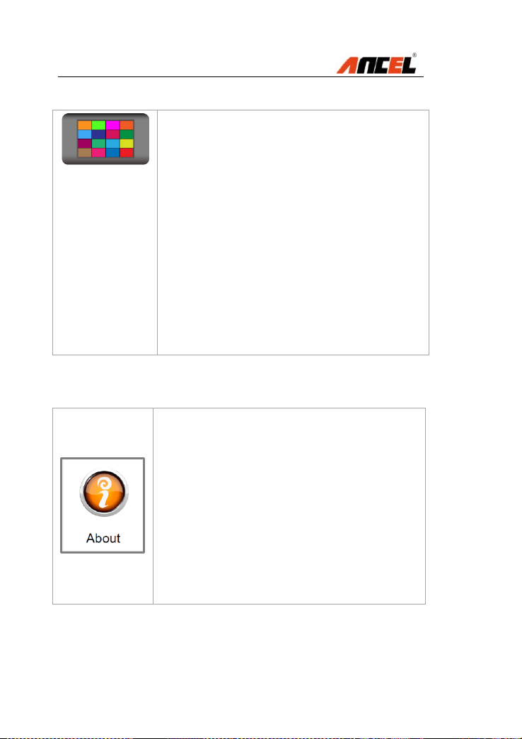
3.10 About
This section provides some important
information such as product serial
number, register password, firmware
version, system software version,
hardware version, manufacture date etc.
How to do:
1) Move the Left/Right or Up/Down
button under the Main Screen to
select the button About.
2) Press OK and the LCD screen will
display some important information.

FX4000 Full System Scan Tool
3.11 Vehicle Coverage
On the basis of all OBD II compliant vehicles, including
those equipped with universal protocol -- Control Area
Network (CAN), ANCEL FX4000 Auto Scanner expands
vehicle system coverage and offers more diagnostic
power to the vehicle technicians.
Featuring expanded global vehicle coverage, the scan
tool offers technicians a significant improvement on model
years covered by supported manufactures. We’ve worked
backwards to include non-OBDII vehicles, which can be
diagnosed by setting up with optional OBDI adaptors.
For a complete listing of all the added vehicle coverage,
download a copy of the official ANCEL FX4000 scan tool
Software Release Note.
3.12 Product Troubleshooting
Vehicle Linking Error
A communication error occurs if the scan tool fails to
communicate with vehicle’s ECU (Electronic Control Unit).
You need to do the following to check up:
Verify that the ignition is ON.
Check if the scan tool’s connector is securely
connected to the vehicle’s DLC.
Turn the ignition off and wait for about 10 seconds.
Turn the ignition back to on and continue the testing.
Verify the control module is not defective.

FX4000 Full System Scan Tool
Operating Error
If the scan tool freezes, then an exception occurs or the
vehicle’s ECU (Electronic Control Unit) is too slow to
respond to requests.
You need to do the following to reset the tool:
Reset the scan tool.
Turn the ignition off and wait for about 10 seconds.
Turn the ignition back to on and continue the testing.
Scan tool doesn’t power up
If the scan tool won’t power up or operates incorrectly in
any other way, you need to do the following to check up:
Check if the scan tool’s connector is securely
connected to the vehicle’s DLC;
Check if the DLC pins are bent or broken. Clean the
DLC pins if necessary.
Check vehicle battery to make sure it is still good with
at least 8.0 volts.
FX4000 Full System Scan Tool
4. Diagnostic operations
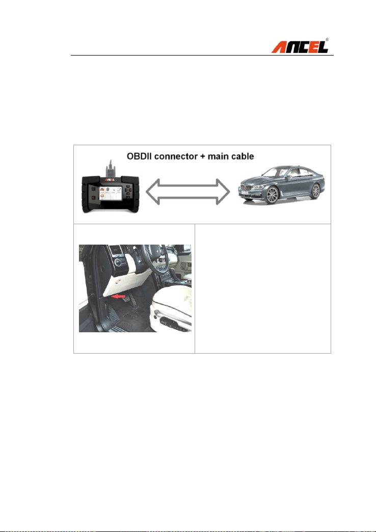
4.1 Start a New Test
Before using the scan tool to diagnose, you must connect
the scan tool to the vehicle with the OBDII connector and
the main cable.
Insert the OBDII connector
into the OBD II socket on
the car correctly.
The OBDII port locations
vary according to the
different car models.
Follow the steps to begin the diagnostics.
1) Turn on the scan tool and wait for the Main Screen.
2) Select Diagnose in the Main Screen.
FX4000 Full System Scan Tool
3) Select EUROPEAN as below:
AMERICAN
ASIAN
EUROPEAN
4) Select BMW for testing (Taking BMW as an example):
ALFA-ROMEO
AUDI
BENZ
BMW
CITROEN
VOLKSWAGEN
FIAT
FORD
FX4000 Full System Scan Tool
5) The page pops out, select item [1] 1 Series as below:
Diagnosis
[1]
1 Series
[2]
2 Series
[3]
3 Series
[4]
4 Series
[5]
5 Series
[6]
6 Series
[7]
7 Series
6) Press OK, the following page will be displayed:
1 Series
[1]
E87 / E88
[2]
F20 / F21
FX4000 Full System Scan Tool
4.2 Start a Quick Test
7) The page will be displayed as below:
E87 / E88
[1]
Quick test
[2]
Drive
[3]
Chassis
[4]
Body
[5]
Service functions
NOTE:
The Quick test on the first line supporting all system
listed in Drive, Chassis and Body.
8) Press OK to confirm the selection [1] Quick test, and
then the below page will be displayed:
Information
Do you want to start the quick test?
Yes
No
FX4000 Full System Scan Tool
9) Press OK to select Yes for starting the quick test.
It will take several seconds to actuate the short test.
Information
Short test have been finished!
Press OK key to continue!
NOTE:
Press Right to select NO and cancel the quick test.
Press Esc to stop the operation during the quick test.
10) Press OK, the below page will be displayed:
Short test
[1]
View Faults in control unit
[2]
View quick test result
[3]
Quick delete
NOTE:
Up/Down: To view items on current page one by one
Left/Right: To view items on next and previous page
FX4000 Full System Scan Tool
11) Press OK, the below page will be displayed:
Short test
DME/DDE (Motor/Diesel Electronics)
1F
29CC
DME: Misfire, several cylinders
EKPS Fuel-pump control
3F
50
Ignition, cylinder 3
67
Knock sensor 4
NOTE:
The scan tool will display all control units with this
item selection.
Up/Down: To view items on current page one by one
Left/Right: To view items on next and previous page
12) Press Down to select the item [2] View quick test
result from the list below:
Short test
[1]
View Faults in control unit
[2]
View quick test result
[3]
Quick delete
FX4000 Full System Scan Tool
13) Press OK, the below page will be displayed:
Short test
CAS Car Access System
No fault code!
EGS transmission control
No fault code!
DME/DDE (Motor/Diesel
Electronics)
1F
EKPS Fuel-pump control system
3F
AL active steering
No fault code!
ARS Dynamic Drive 2
No fault code!
NOTE:
The scan tool will display all quick test results with
this item selection.
Up/Down: To view items on current page one by one
Left/Right: To view items on next and previous page
14) Press Down to select [3] Quick delete from the list:
Short test
[1]
View Faults in control unit
[2]
View quick test result
[3]
Quick delete
FX4000 Full System Scan Tool
15) Press OK, the below page will be displayed:
Quick delete
[1]
Clear fault in control unit
[2]
Clear faults of all control unit
NOTE:
Up/Down: To view items on current page one by one
Left/Right: To view items on next and previous page
16) Press OK to confirm the first choice [1] Clear fault in
control unit. The following information will be displayed:
Information
Quick delete is successfully finished!
Press OK key to continue!
FX4000 Full System Scan Tool
17) After pressing OK, the page will be displayed:
Short test
CAS Car Access System
No fault code!
EGS transmission control
No fault code!
DME/DDE (Motor/Diesel
Electronics)
1F
EKPS Fuel-pump control system
3F
AL active steering
No fault code!
ARS Dynamic Drive 2
No fault code!
NOTE:
Up/Down: To view items on current page one by one
Left/Right: To view items on next and previous page
Esc: Back to previous menu
4.3 Read Identification
18) After pressing OK, the below page will be displayed
CAS Car Access System
[1]
Identification
[2]
Read fault memory
[3]
Clear fault memory
[4]
Diagnosis request
FX4000 Full System Scan Tool
19) Press OK to confirm the first choice [1] Identification.
The following information will be displayed:
Identification
CAS Car Access System
Physical hardware number
8353731
BMW Part number
8353731
Coding index
48
Date of manufacture
(DD.MM.YYYY)
30.07.2015
Diagnosis index
12611
NOTE:
Up/Down: To view items on current page one by one
Left/Right: To view items on next and previous page
Esc/Enter: Back to previous menu
4.4 Read fault memory / Read DTC
20) Press Down to select the item [2] Read fault
memory from the list below:
CAS Car Access System
[1]
Identification
[2]
Read fault memory
[3]
Clear fault memory
[4]
Diagnosis request
FX4000 Full System Scan Tool
21) After pressing OK, the below page will be displayed
Information
No fault code!
Press OK key to continue!
NOTE:
Enter: Back to previous menu
4.5 Clear fault memory / Clear DTC
22) After pressing OK, the scan tool will be back to
previous menu shown as below, and select the item [3]
Clear fault memory:
CAS Car Access System
[1]
Identification
[2]
Read fault memory
[3]
Clear fault memory
[4]
Diagnosis request

FX4000 Full System Scan Tool
23) The following page will be displayed as below
Information
Do you want to carry out this function?
Yes
No
NOTE:
Press Right to select NO and cancel the quick test.
24) Press OK to select Yes and delete fault memory.
Information
Erase fault code(s) successfully!
Press OK key to continue!
NOTE:
Enter: Back to previous menu
FX4000 Full System Scan Tool
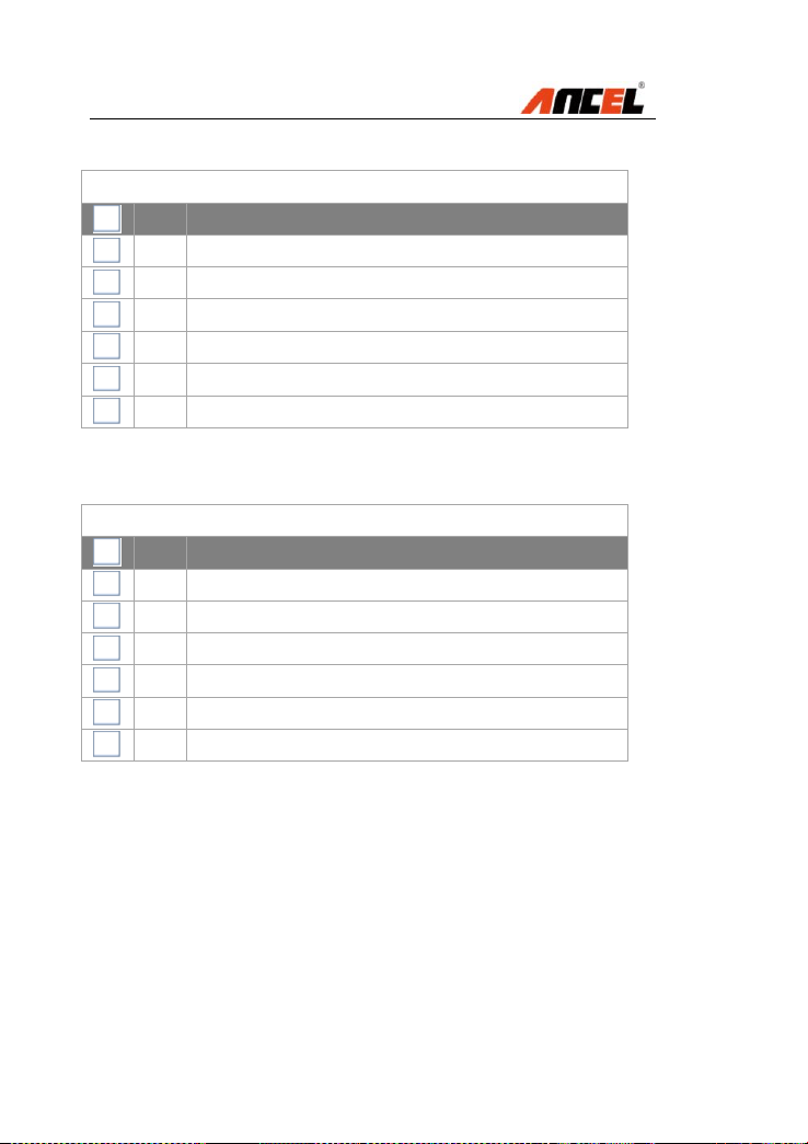
4.6 Read live data / DataStream
25) After pressing OK, the scan tool will be back to
previous menu shown as below, and select the item [4]
Diagnosis request:
Diagnosis request
[1]
Programming
[2]
Internal Hall sensors
[3]
Inputs
[4]
Terminals
[5]
Remote control
[6]
Key
[7]
Remote control battery status
28) Press Down to select [4] Terminals from the list:
Diagnosis request
[1]
Programming
[2]
Internal Hall sensors
[3]
Inputs
[4]
Terminals
[5]
Remote control
[6]
Key
[7]
Remote control battery status
FX4000 Full System Scan Tool
29) After pressing OK, the page will be displayed:
Diagnosis request
[1]
Terminal 30E
[2]
Terminal 30L
[3]
Terminal 15-1
[4]
Terminal 15-2
[5]
Terminal 15-3
[6]
Terminal 15-4
[7]
Terminal 15, Wake Up (PT CAN)
30) Press Left and Right to view next or previous pages.
Diagnosis request
[8]
Terminal 15, Wake Up (ACC)
[9]
Voltage, terminal 50E
[10]
Current, terminal 50L
FX4000 Full System Scan Tool
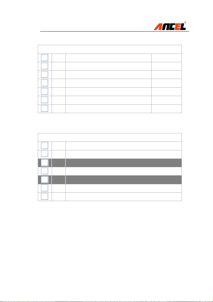
31) Press OK to select all items listed.
Diagnosis request
[1]
Terminal 30E
16.65 (V)
[2]
Terminal 30L
16.65 (V)
[3]
Terminal 15-1
16.65 (V)
[4]
Terminal 15-2
16.65 (V)
[5]
Terminal 15-3
16.65 (V)
[6]
Terminal 15-4
16.65 (V)
[7]
Terminal 15, Wake Up (PT CAN)
16.65 (V)
32) Press Fn to select items requested.
Diagnosis request
[1]
Terminal 30E
[2]
Terminal 30L
[3]
Terminal 15-1
[4]
Terminal 15-2
[5]
Terminal 15-3
[6]
Terminal 15-4
[7]
Terminal 15, Wake Up (PT CAN)
NOTE: The scan tool will display live data in graphic.

FX4000 Full System Scan Tool
33) Press Down to select [5] Service functions:
E87 / E88
[1]
Quick test
[2]
Drive
[3]
Chassis
[4]
Body
[5]
Service functions
NOTE:
ANCEL FX4000 scan tool provides other system
available, such as Drive, Chassis, Body, ABS etc.
5. Software Update
This function always you to update the scan tool software
through a computer
5.1 Register the scan tool
User would update the scan tool ONLY after you have
registered the tool on ANCEL website:
www.anceldiret.com Then you could download software,
update online retrieve information and get warranty
services.
NOTE: Prior to registration, please confirm your
network is working properly.
FX4000 Full System Scan Tool
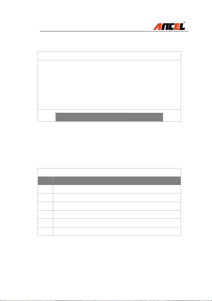
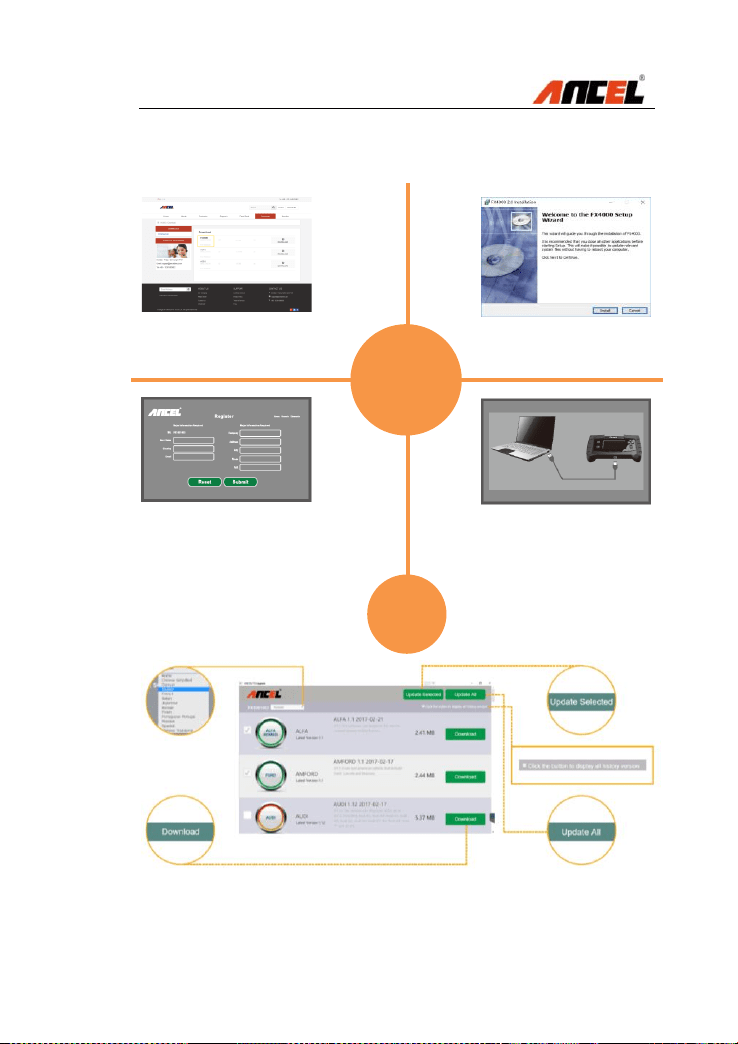
5.2 Software Update Flow Chart
Visit ANCEL website as below
www.anceldirect.com/download.html
Download FX4000 Update
Client and then following the
instructions
Input details for online registration
and submit the form. Keep in mind
the user information and download
latest software
Connect PC and the FX4000
scan tool with USB cable
before software updating
1
2
4
3
5

FX4000 Full System Scan Tool
6. Warranty and Service
6.1 Limited One Year Warranty
Subject to the conditions of this limited warranty, ANCEL
warrants its customer that this product is free of defects in
material and workmanship at the time of its original
purchase for a subsequent period of one year.
In the event this product fails to operate under normal use,
during the warranty period, due to defects in materials
and workmanship, ANCEL will, at its sole option, either
repair or replace the product in accordance with the terms
and conditions stipulated herein.
Terms and Conditions
1. If ANCEL repairs or replaces the product, the repaired
or replaced product shall be warranted for the
remaining time of the original warranty period. No
charge will be made to the customer for replacement
parts or labor charges incurred by ANCEL in repairing
or replacing the defective parts.
2. The customer shall have no coverage or benefits
under this limited warranty if any of the following
conditions are applicable:
a) The product has been subjected to abnormal use,
abnormal conditions, improper storage, exposure to
moisture or dampness, unauthorized modifications,
unauthorized repair, misuse, neglect, abuse,
accident, alteration, improper installation, or other
acts which are not the fault of ANCEL, including
damage caused by shipping.
3. The customer shall bear the cost of shipping the
product to ANCEL. And ANCEL shall bear the cost of
shipping the product back to the customer after the
completion of service under this limited warranty.

FX4000 Full System Scan Tool
4. ANCEL does not warrant uninterrupted or error-free
operation of the product. If a problem develops
during the limited warranty period, the consumer
shall take the following step-by-step procedure:
a) The customer shall return the product to the place of
purchase for repair or replacement processing,
contact your local ANCEL distributor or visit our
website www.anceldirect.com to get further info
b) The customer shall include a return address, daytime
phone number and/or fax number, complete
description of the problem and original invoice
specifying date of purchase and serial number.
c) The customer will be billed for any parts or labor
charges not covered by this limited warranty.
d) ANCEL will repair the Product under the limited
warranty within 30 days after receipt of the product. If
ANCEL cannot perform repairs covered under this
limited warranty within 30 days, or after a reasonable
number of attempts to repair the same defect,
ANCEL at its option, will provide a replacement
product or refund the purchase price of the product
less a reasonable amount for usage.
e) If the product is returned during the limited warranty
period, but the problem with the product is not
covered under the terms and conditions of this
limited warranty, the customer will be notified and
given an estimate of the charges the customer must
pay to have the product repaired, with all shipping
charges billed to the customer. If the estimate is
refused, the product will be returned freight collect. If
the product is returned after the expiration of the
limited warranty period, ANCEL normal service
policies shall apply and the customer will be
responsible for all shipping charges.

FX4000 Full System Scan Tool
5. Any implied warranty of merchantability, or fitness for
a particular purpose or use, shall be limited to the
duration of the foregoing limited written warranty.
Otherwise, the foregoing limited warranty is the
consumer’s sole and exclusive remedy and is in lieu
of all other warranties, express or implied. ANCEL
shall not be liable for special, incidental, punitive or
consequential damages, including but not limited
6.2 Service Procedures
If you have any questions, please contact your local store,
distributor or visit our website at www.anceldirect.com.
If it becomes necessary to return the scan tool for repair,
contact your local distributor for more information.
FAQ (Frequency Ask Questions)
Why the Vehicle Linking Error?
A communication error occurs if the scan tool fails to communicate
with the vehicle’s ECU (Electronic Control Unit)
Answer:
Verify that the ignition is ON.
Check if the scan tool’s connector is securely connected to the
vehicle’s DLC.
Turn the ignition off and wait for about 10 seconds and turn the
ignition back to ON and continue the testing.
Verify the control module is not defective

FX4000 Full System Scan Tool
Why the Operating Error?
If the scan tool freezes, then an exception occurs or the vehicle’s ECU
is too slow to respond the requests.
Answer:
Reset the scan tool first and turn the ignition off and wait for about 10
seconds and turn the ignition back to ON and continue the testing.
Why the Scan Tool Doesn’t Power Up?
If the scan tool won’t power up or operates incorrectly in any other
way.
Answer:
Check if the scan tool’s connector is securely connected to the
vehicle’s DLC
Check if the DLC pins are bent or broken. Clean the DLC pins if
necessary.
Check vehicle battery to make sure it is still good with at least 8.0 V
Why Cannot Install the FX4000 Update Client Correctly?
After installing the FX4000 Update Client, the system won’t accept the
serial number for the FX machines.
Answer:
You need to connect the PC and the FX machines with the USB cable
before software download

FX4000 Full System Scan Tool
OBDSPACE TECHNOLOGY CO ., LTD
Runfeng office longhua district Shenzhen
GuangDong 518000 P.R China
TEL: 0755-81751202
E-Mail: sales@anceldirect.com
Website: www.anceldirect.com