
BRAVOS ® STEAM FABRIC CARE
SYSTEM GAS DRYER
USE & CARE GUIDE
p 'K
SECHEUSE A GAZ BRAVOS ®AVEC
SYSTEME DE SOIN
'K
DES TISSUS A LA VAPEUR
GUIDE D'UTILISATION ET D'ENTRETIEN
FOR QUESTIONS ABOUT FE,a(IURES, OPERATION/PERFORMANCE, PARTS, ACCESSORIES OR SERVICE
CAll: 1.800.688.9900
IN CANADA, CAll: 1.800.807.6777
VISIT OUR WEBSITE AT WWW.MAYTAG.COM
IN CANADA, WWW.MAYTAG.CA
AU CANADA, POUR ASSISTANCE, INSTAllATION OU SERVICE, COMPOSEZ IE : 1.800.807.6777
OU VISITEZ NOTRE SITE INTERNET ,_
WWW. M AYTAG. CA
W10201177A

,i_!_ii!i!i!i!i!i!i!i!i!i!i!i!i!i!i!i!i!i!i!i!i!i!i!i_i_i_ii!i¸i!i!i!i!i!i!i!i_i_ii_ii_ii_ii_ii_ii_ii_ii_ii_ii_ii_ii_ii_ii_i_iiiiYiiiiii//li¸il¸iiii_ii,i_ii,i_ii,i_ii,i_ii,i_i_iii_i_ii_il'ii_i_iil'ii_i_iil_i_ii_i_ii_i_ii_ii_i_ii_:ii:_:i_:ii:_:i_:ii:_:i_:ii:_:i_:ii:_:i_:ii:_:i_:ii:_:i_:_i_::¸ _:iii!ii,l,ii_,,¸¸¸¸_!_iiiiiiiii_i_ ¸il¸ii_ii_ii¸I¸I¸il¸ii_ii¸ii_ii¸ii_ii¸ii_iil¸ii_i_iil¸I¸iiiii_iiiii_i_i_ii_i_iiiii_ii_iii_ii_iii_iiiiiiiiiiiiiiiiiiiiiiiiiiiiiiiiiiiiiiiiiiiiiiiiiiiiiiiiiiii_!_!!
TABLE OF CONTENTS
DRYER SAFETY .......................................................................................................................... 3
INSTALLATION INSTRUCTIONS ............................................................................................. 5
Tools and Parts ....................................................................................................................... 5
I.ocation Requirements .......................................................................................................... 5
Electrical Requirements .......................................................................................................... 7
Gas Supply Requirements ...................................................................................................... 7
Venting Requirements ............................................................................................................ 8
Plan Vent System .................................................................................................................. 10
Install Vent System ............................................................................................................... 11
Install I_eveling I.egs ............................................................................................................. 11
Make Gas Connection .......................................................................................................... 12
Connect Vent ....................................................................................................................... 12
Connect Inlet Hose ............................................................................................................... 13
I.eve[ Dryer .......................................................................................................................... 13
Reverse Door Swing ............................................................................................................. 14
Complete Installation ........................................................................................................... 16
DRYER USE.............................................................................................................................. 17
Starting Your Dryer ............................................................................................................... 1 7
Stopping, Pausing, or Restarting ........................................................................................... 18
Drying and Cycle Tips .......................................................................................................... 18
Status I_ights .......................................................................................................................... 19
Cycles .................................................................................................................................. 19
Modifiers .............................................................................................................................. 21
Options ................................................................................................................................ 21
End Signal ............................................................................................................................ 22
Changing Cycles, Modifiers, and Options ............................................................................ 22
Drying Rack Option ............................................................................................................. 22
DRYER CARE ........................................................................................................................... 23
Cleaning the Dryer I.ocation ................................................................................................ 23
Cleaning the I_int Screen ...................................................................................................... 23
Cleaning the Dryer Interior ................................................................................................... 24
Removing Accumulated I.int ................................................................................................ 24
Water Inlet Hoses ................................................................................................................. 24
Vacation, Storage and Moving Care ..................................................................................... 24
Changing the Drum Light ..................................................................................................... 24
TROUBLESHOOTING ............................................................................................................. 25
Dryer Operation ................................................................................................................... 25
Dryer Results ........................................................................................................................ 26
ASSISTANCE OR SERVICE ....................................................................................................... 28
In the U.S.A .......................................................................................................................... 28
In Canada ............................................................................................................................. 28
ACCESSORIES ......................................................................................................................... 28
WARRANTY ............................................................................................................................ 29
TABLE DES MATIERES
SI_CURITI_ DE LA SI_CHEUSE ................................................................................................... 30
INSTRUCTIONS D'INSTALLATION ....................................................................................... 33
Outi[[age et pi_ces ............................................................................................................... 33
Exigences d'emp[acement .................................................................................................... 33
Sp6cifications 6[ectriques ..................................................................................................... 35
A[imentation en gaz ............................................................................................................. 35
Exigences concernant ['6vacuation ...................................................................................... 37
Planification du syst_me d'6vacuation ................................................................................. 38
InstaINation du syst_me d'6vacuation .................................................................................... 40
Installation des pieds de nivellement .................................................................................... 40
Raccordement au gaz ........................................................................................................... 40
Raccordement du conduit d'6vacuation ............................................................................... 41
Raccordement des tuyaux d'a[imentation ............................................................................ 41
R6g[age de ['aplomb de [a s6cheuse ..................................................................................... 42
Inversion du sens d'ouverture de Haporte ............................................................................. 42
Achever ['installation ............................................................................................................ 44
UTILISATION DE LA SI_CHEUSE ............................................................................................. 46
Mise en marche de Has6cheuse ............................................................................................ 46
Arr_t, pause ou remise en marche ........................................................................................ 48
Conseils pour mes6chage et [es programmes ........................................................................ 48
T6moins [umineux ................................................................................................................ 48
Programmes ......................................................................................................................... 49
Modificateurs ....................................................................................................................... 50
Options ................................................................................................................................ 51
End Signal (signal de fin de programme) .............................................................................. 51
Changement des programmes, modificateurs, et options ..................................................... 52
Option de grille de s6chage ................................................................................................. 52
ENTRETIEN DE LA SI_CHEUSE ................................................................................................ 53
Nettoyage de ['emplacement de Has6cheuse ........................................................................ 53
Nettoyage du filtre _ charpie ................................................................................................ 53
Nettoyage de ['int6rieur de Has6cheuse ................................................................................ 54
Retrait de Hacharpie accumul6e ........................................................................................... 54
Tuyaux d'arriv6e d'eau ......................................................................................................... 54
Pr6cautions _ prendre avant [es vacances, un entreposage ou un d6m6nagement ............... 54
Changement de ['ampoule d'6clairage du tambour .............................................................. 55
DI_PANNAGE .......................................................................................................................... 55
Fonctionnement de [a s6cheuse ........................................................................................... 55
R6sultats de Has6cheuse ....................................................................................................... 56
ASSISTANCE OU SERVICE ...................................................................................................... 58
Au Canada ........................................................................................................................... 58
ACCESSOIRES .......................................................................................................................... 58
GARANTIE ............................................................................................................................... 59

DRYER SAFETY
Your safety and the safety of others are very important.
We have provided many important safety messages in this manual and on your appliance. Always read and obey all safety
messages.
This is the safety alert symbol.
This symbol alerts you to potential hazards that can kill or hurt you and others.
All safety messages will follow the safety alert symbol and either the word "DANGER" or "WARNING."
These words mean:
You can be killed or seriously injured if you don't immediately
follow instructions.
You can be killed or seriously injured if you don't follow
instructions.
All safety messages will tell you what the potential hazard is, tell you how to reduce the chance of injury, and tell you what can
happen if the instructions are not followed.
WARNING: For your safety, the information in this manual must be followed to minimize
the risk of fire or explosion, or to prevent property damage, personal injury, or death.
- Do not store or use gasoline or other flammable vapors and liquids in the vicinity of this
or any other appliance.
- WHAT TO DO IF YOU SMELL GAS:
• Do not try to light any appliance.
• Do not touch any electrical switch; do not use any phone in your building.
• Clear the room, building, or area of all occupants.
• Immediately call your gas supplier from a neighbor's phone. Follow the gas supplier's
instructions.
• If you cannot reach your gas supplier, call the fire department.
- Installation and service must be performed by a qualified installer, service agency, or
the gas supplier.
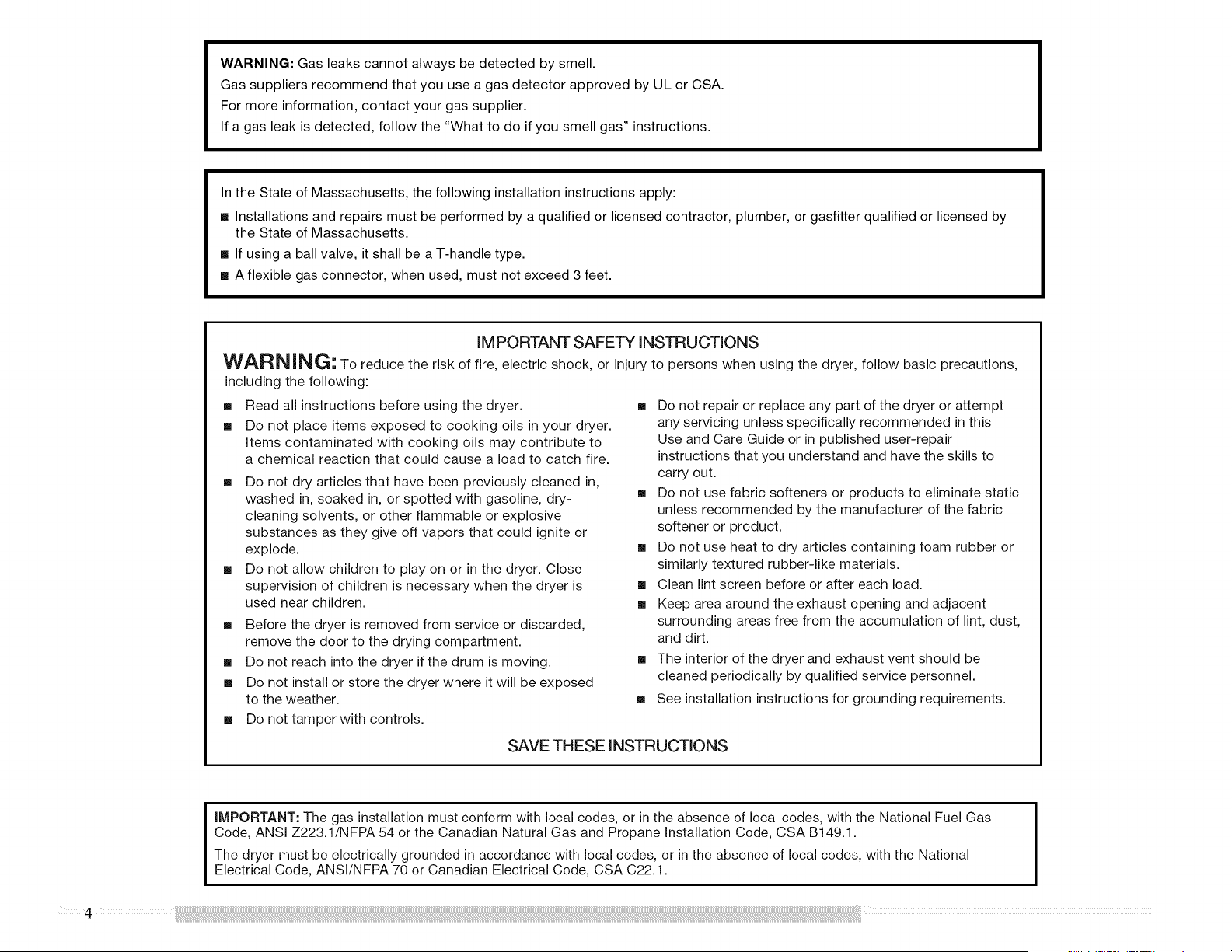
WARNING: Gas leaks cannot always be detected by smell.
Gas suppliers recommend that you use a gas detector approved by UL or CSA.
For more information, contact your gas supplier.
If a gas leak is detected, follow the "What to do if you smell gas" instructions.
In the State of Massachusetts, the following installation instructions apply:
[] Installations and repairs must be performed by a qualified or licensed contractor, plumber, or gasfitter qualified or licensed by
the State of Massachusetts.
[] If using a ball valve, it shall be a T-handle type.
[] A flexible gas connector, when used, must not exceed 3 feet.
IM PORTANT SAFETY INSTRUCTIONS
WAR N iNG" To reduce the risk of fire, electric shock, or injury to persons when using the dryer, follow basic precautions,
including the following:
[] Read all instructions before using the dryer.
[] Do not place items exposed to cooking oils in your dryer.
Items contaminated with cooking oils may contribute to
a chemical reaction that could cause a load to catch fire.
[] Do not dry articles that have been previously cleaned in,
washed in, soaked in, or spotted with gasoline, dry-
cleaning solvents, or other flammable or explosive
substances as they give off vapors that could ignite or
explode.
[] Do not allow children to play on or in the dryer. Close
supervision of children is necessary when the dryer is
used near children.
[] Before the dryer is removed from service or discarded,
remove the door to the drying compartment.
[] Do not reach into the dryer if the drum is moving.
[] Do not install or store the dryer where it will be exposed
to the weather.
[] Do not tamper with controls.
[] Do not repair or replace any part of the dryer or attempt
any servicing unless specifically recommended in this
Use and Care Guide or in published user-repair
instructions that you understand and have the skills to
carry out.
[] Do not use fabric softeners or products to eliminate static
unless recommended by the manufacturer of the fabric
softener or product.
[] Do not use heat to dry articles containing foam rubber or
similarly textured rubber-like materials.
[] Clean lint screen before or after each load.
[] Keep area around the exhaust opening and adjacent
surrounding areas free from the accumulation of lint, dust,
and dirt.
[] The interior of the dryer and exhaust vent should be
cleaned periodically by qualified service personnel.
[] See installation instructions for grounding requirements.
SAVE THESE INSTRUCTIONS
iMPORTANT: The gas installation must conform with local codes, or in the absence of local codes, with the National Fuel Gas
Code, ANSI Z223.1/NFPA 54 or the Canadian Natural Gas and Propane Installation Code, CSA B149.1.
The dryer must be electrically grounded in accordance with local codes, or in the absence of local codes, with the National
Electrical Code, ANSI/NFPA 70 or Canadian Electrical Code, CSA C22.1.
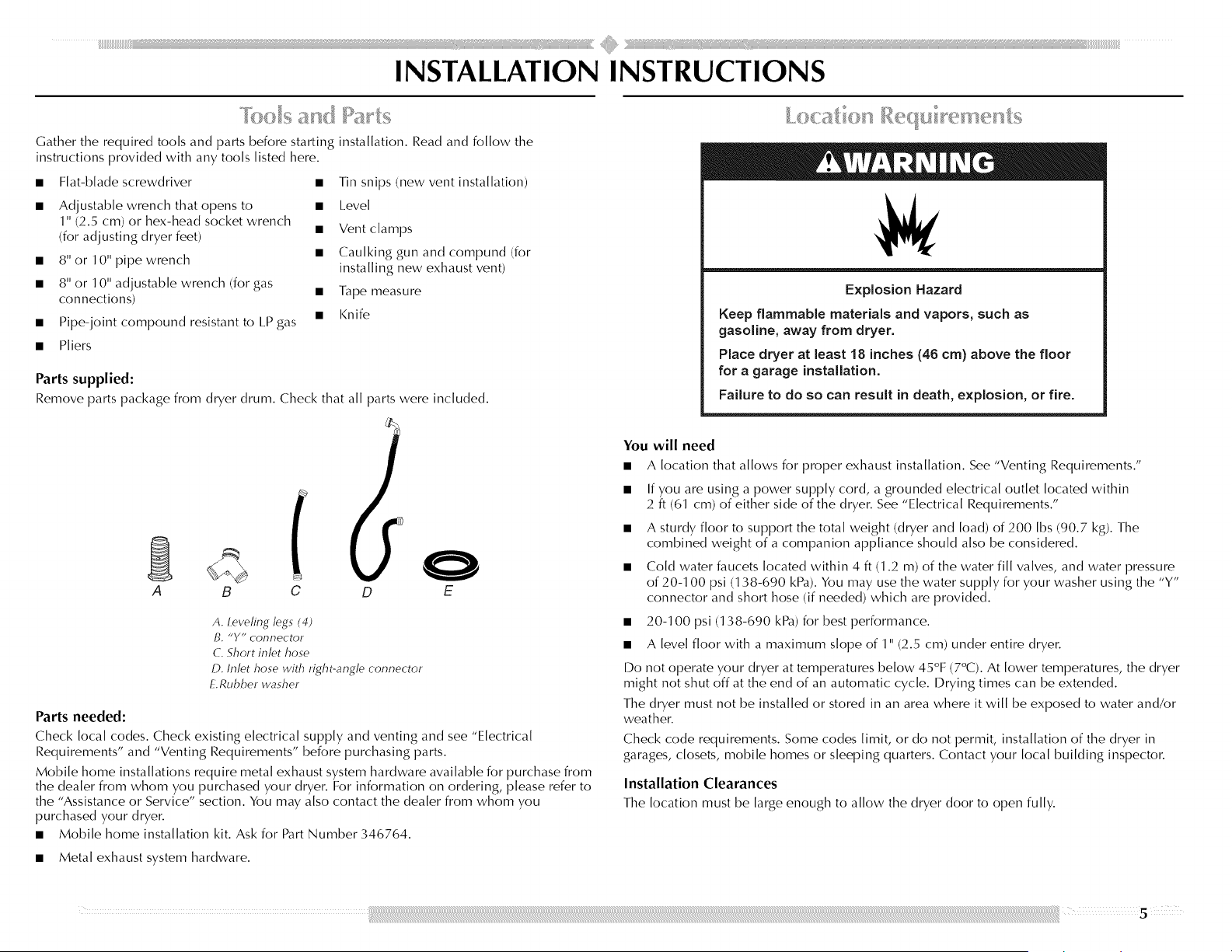
Gather the required tools and parts before starting installation. Read and follow the
instructions provided with any tools listed here.
• Flat-blade screwdriver •
• Adjustable wrench that opens to
1" (2.5 cm) or hex-head socket wrench
(for adjusting dryer feet)
• 8" or 10" pipe wrench
• 8" or 10" adjustable wrench (for gas
connections)
• Pipe-joint compound resistant to I.P gas
Tin snips (new vent installation)
• I.evel
• Vent clamps
• Caulking gun and compund (for
installing new exhaust vent)
• Tape measure
• Knife
• Pliers
Parts supplied:
Remove parts package from dryer drum. Check that all parts were included.
1
A
B C D E
A. Levering legs (4)
B. "Y" connector
C. Short inlet hose
D. Inlet hose with right-angle connector
E. Rubber washer
Parts needed:
Check local codes. Check existing electrical supply and venting and see "Electrical
Requirements" and "Venting Requirements" before purchasing parts.
Mobile home installations require metal exhaust system hardware available for purchase from
the dealer from whom you purchased your dryer. For information on ordering, please refer to
the "Assistance or Service" section. You may also contact the dealer from whom you
purchased your dryer.
• Mobile home installation kit. Ask for Part Number 346764.
Explosion Hazard
Keep flammable materials and vapors, such as
gasoline, away from dryer.
Place dryer at least 18 inches (46 cm) above the floor
for a garage installation.
Failure to do so can result in death, explosion, or fire.
You will need
• A location that allows for proper exhaust installation. See "Venting Requirements."
• If you are using a power supply cord, a grounded electrical outlet located within
2 ft (61 cm) of either side of the dryer. See "Electrical Requirements."
• A sturdy floor to support the total weight (dryer and load) of 200 Ibs (90.7 kg). The
combined weight of a companion appliance should also be considered.
• Cold water faucets located within 4 ft (1.2 m) of the water fill valves, and water pressure
of 20-100 psi (138-690 kPa). You may use the water supply for your washer using the "Y"
connector and short hose (if needed) which are provided.
• 20-100 psi (138-690 kPa) for best performance.
• A level floor with a maximum slope of 1" (2.5 cm) under entire dryer.
Do not operate your dryer at temperatures below 45°F (7°C). At lower temperatures, the dryer
might not shut off at the end of an automatic cycle. Drying times can be extended.
The dryer must not be installed or stored in an area where it will be exposed to water and/or
weather.
Check code requirements. Some codes limit, or do not permit, installation of the dryer in
garages, closets, mobile homes or sleeping quarters. Contact your local building inspector.
Installation Clearances
The location must be large enough to allow the dryer door to open fully.
• Metal exhaust system hardware.
Dryer Dimensions
*Most installations require a minimum 5" (12.7 cm) clearance behind the dryer for the
exhaust vent with elbow. See "Venting Requirements."
Installation spacing for recessed area or closet installation
The following spacing dimensions are recommended for this dryer. This dryer has been tested
for spacing of O" (O cm) clearance on the sides and rear. Recommended spacing should be
considered for the following reasons:
• Additional spacing should be considered for ease of installation and servicing.
• Additional clearances might be required for wall, door and floor moldings.
• Additional spacing should be considered on all sides of the dryer to reduce noise transfer.
• For closet installation, with a door, minimum ventilation openings in the top and bottom
of the door are required. I.ouvered doors with equivalent ventilation openings are
acceptable.
• Companion appliance spacing should also be considered.
• Additional spacing is required if you exhaust out the rear of the dryer to either the right or
left side.
18"*--_
(45.7crn)
I'
II °1°
b""""""-_
H 1-t-114"_.*
i" _ _ 29"-_ _1" -HI"*I" 29,/,"'4 5"÷
(2.5cm) (73.7crn) (2.5crn) (2.5cm)(74.3crn)(12.7crn)
A B
48in. 2._
(310cm2)
24in.2.
(155cmZ)-
._ 3"*
(7.5cm)
(7.5cm)
T
C
A. Recessed area
B. Side view -c/oset or confined area
C. Closet door with vents
*Required spacing
Mobile home - Additional installation requirements
This dryer is suitable for mobile home installations. The installation must conform to the
Manufactured Home Construction and Safety Standard, Title 24 CFR, Part 3280 (formerly the
Federal Standard for Mobile Home Construction and Safety, Title 24, HUD Part 280) or
Standard CAN/CSA-Z240 MH.
Mobile home installations require:
• Metal exhaust system hardware, which is available for purchase from your dealer.
• Mobile Home Installation Kit Part Number 346764. See "Tools and Parts" section for
information on ordering.
• Special provisions must be made in mobile homes to introduce outside air into the dryer.
The opening (such as a nearby window) should be at [east twice as large as the dryer
exhaust opening.
6
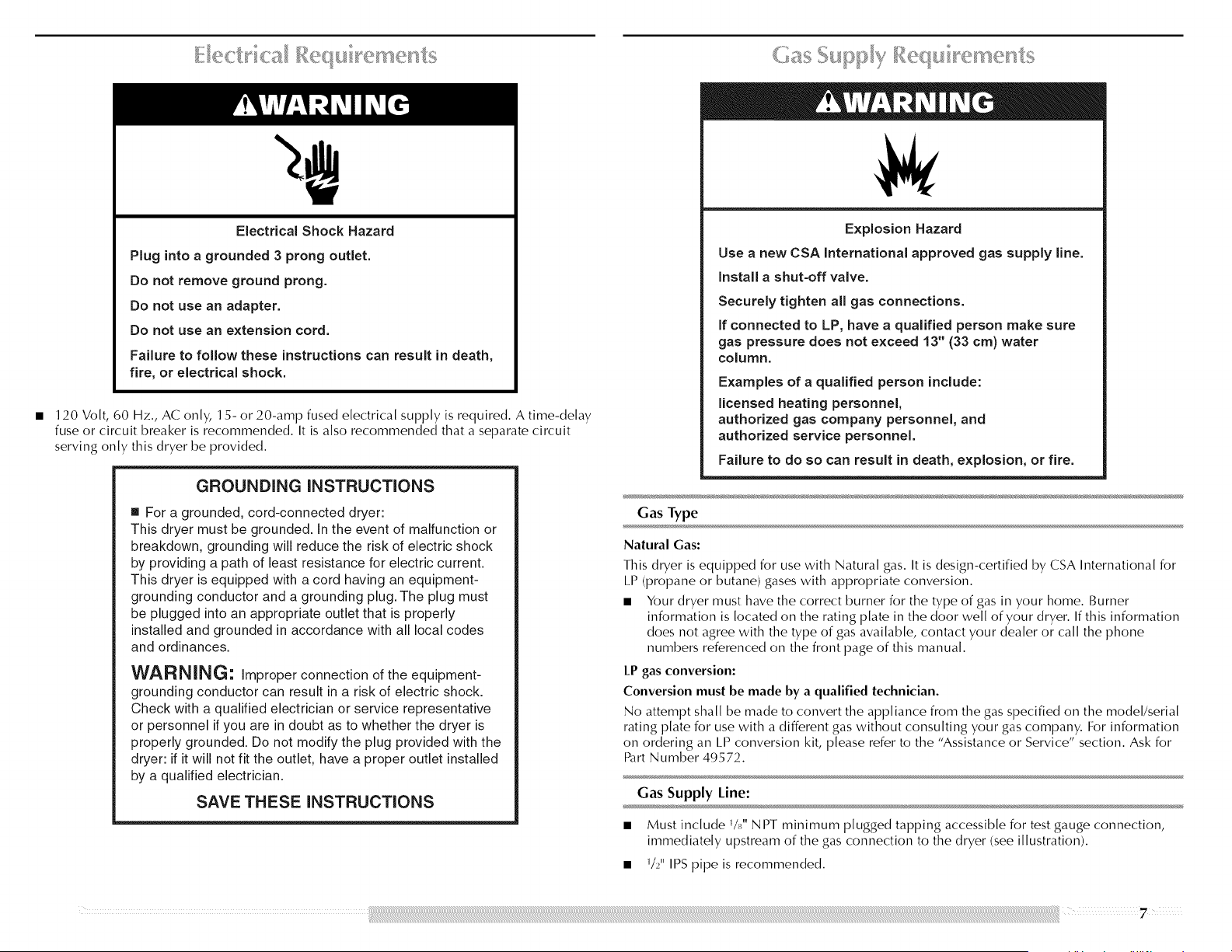
Electrical Shock Hazard
Plug into a grounded 3 prong outlet.
Do not remove ground prong.
Do not use an adapter.
Do not use an extension cord.
Failure to follow these instructions can result in death,
fire, or electrical shock.
120 Volt, 60 Hz., AC only, 15- or 20-amp fused electrical supply is required. A time-delay
fuse or circuit breaker is recommended. It is also recommended that a separate circuit
serving only this dryer be provided.
GROUNDING INSTRUCTIONS
• For a grounded, cord-connected dryer:
This dryer must be grounded. In the event of malfunction or
breakdown, grounding will reduce the risk of electric shock
by providing a path of least resistance for electric current.
This dryer is equipped with a cord having an equipment-
grounding conductor and a grounding plug. The plug must
be plugged into an appropriate outlet that is properly
installed and grounded in accordance with all local codes
and ordinances.
WARNING: Improper connection of the equipment-
grounding conductor can result in a risk of electric shock.
Check with a qualified electrician or service representative
or personnel if you are in doubt as to whether the dryer is
properly grounded. Do not modify the plug provided with the
dryer: if it will not fit the outlet, have a proper outlet installed
by a qualified electrician.
SAVE THESE INSTRUCTIONS
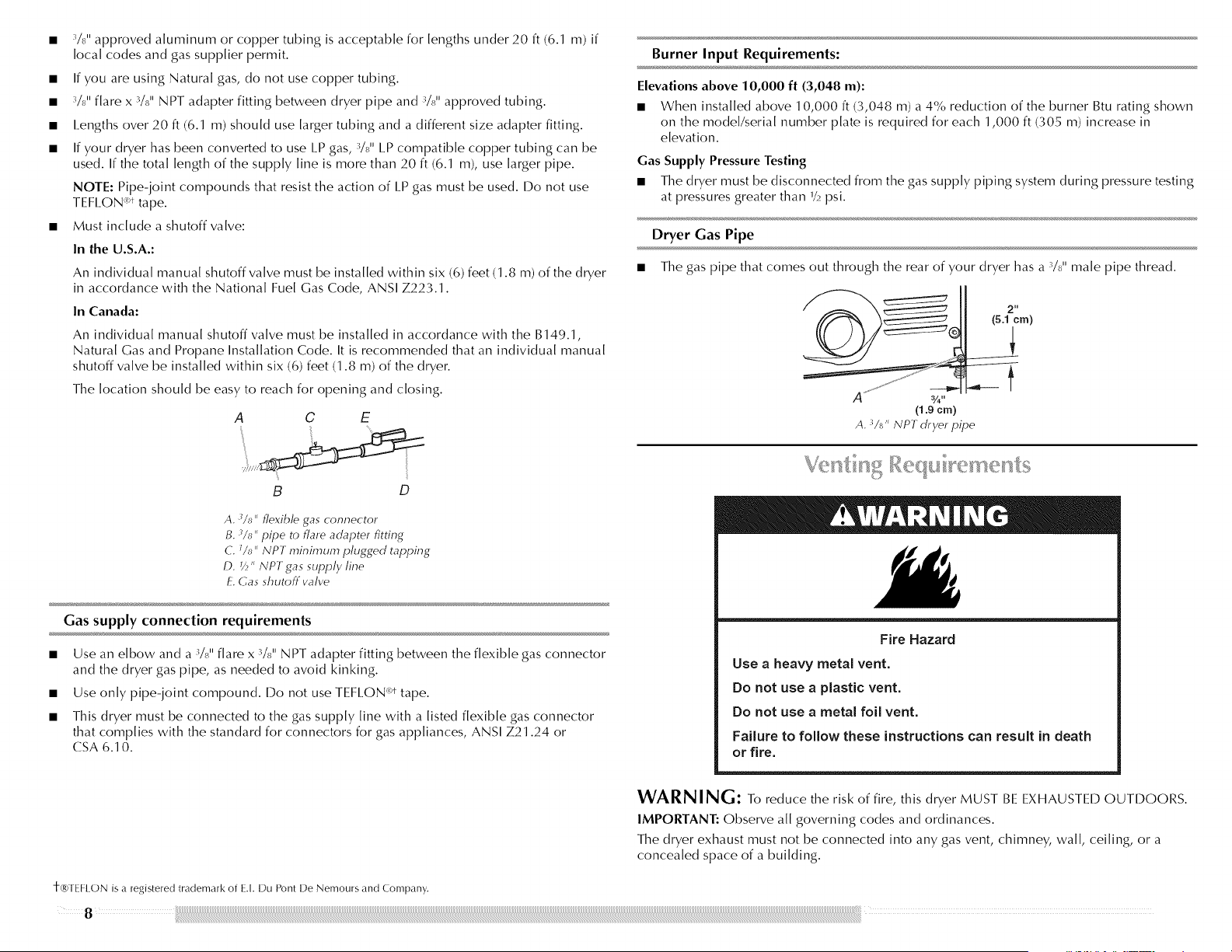
Explosion Hazard
Use a new CSA International approved gas supply line.
Install a shut-off valve.
Securely tighten all gas connections.
If connected to LP, have a qualified person make sure
gas pressure does not exceed 13" (33 cm) water
column.
Examples of a qualified person include:
licensed heating personnel,
authorized gas company personnel, and
authorized service personnel.
Failure to do so can result in death, explosion, or fire.
Gas Type
Natural Gas:
This dryer is equipped for use with Natural gas. It is design-certified by CSA International for
I.P (propane or butane) gases with appropriate conversion.
• Your dryer must have the correct burner for the type of gas in your home. Burner
information is located on the rating plate in the door well of your dryer. If this information
does not agree with the type of gas available, contact your dealer or call the phone
numbers referenced on the front page of this manual.
LP gas conversion:
Conversion must be made by a qualified technician.
No attempt shall be made to convert the appliance from the gas specified on the model/serial
rating plate for use with a different gas without consulting your gas company. For information
on ordering an [.P conversion kit, please refer to the "Assistance or Service" section. Ask for
Part Number 49572.
Gas Supply Line:
• Must include VJ' N PT minimum plugged tapping accessible for test gauge connection,
immediately upstream of the gas connection to the dryer (see illustration).
• W' IPS pipe is recommended.
-_$11 approved aluminum or copper tubing is acceptable for lengths under 20 ft (6.1 m) if
local codes and gas supplier permit.
If you are using Natural gas, do not use copper tubing.
4/8" flare x 3/8" NPT adapter fitting between dryer pipe and 3/8" approved tubing.
I.engths over 20 ft (6.1 m) should use larger tubing and a different size adapter fitting.
If your dryer has been converted to use I.P gas, 4/8" I.P compatible copper tubing can be
used. If the total length of the supply line is more than 20 ft (6.1 m), use larger pipe.
NOTE: Pipe-joint compounds that resist the action of I.P gas must be used. Do not use
TEFI.ON "t tape.
Must include a shutoff valve:
In the U.S.A.:
An individual manual shutoff valve must be installed within six (6) feet (1.8 m) of the dryer
in accordance with the National Fuel Gas Code, ANSI Z223.1.
In Canada:
An individual manual shutoff valve must be installed in accordance with the B149.1,
Natural Gas and Propane Installation Code. It is recommended that an individual manual
shutoff valve be installed within six (6) feet (1.8 m) of the dryer.
The location should be easy to reach for opening and closing.
A O E
B D
A. _/t_" flexible gas connector
B. _/s" pipe to flare adapter fitting
C. J/_" NPT minimum plugged tapping
D. _/_" NPT gas supply line
E. Gas shutoff valve
Gas supply connection requirements
Use an elbow and a _/s II flare x 3/811 NPT adapter fitting between the flexible gas connector
and the dryer gas pipe, as needed to avoid kinking.
Use only pipe-joint compound. Do not use TEFI.ON _t tape.
This dryer must be connected to the gas supply line with a listed flexible gas connector
that complies with the standard for connectors for gas appliances, ANSI Z21.24 or
CSA 6.10.
Burner Input Requirements:
Elevations above 10,000 ft (3,048 m):
• When installed above 10,000 ft (3,048 m) a 4% reduction of the burner Btu rating shown
on the model/serial number plate is required for each 1,000 ft (305 m) increase in
elevation.
Gas Supply Pressure Testing
• The dryer must be disconnected from the gas supply piping system during pressure testing
at pressures greater than _/_psi.
Dryer Gas Pipe
The gas pipe that comes out through the rear of your dryer has a s/sm'male pipe thread.
(5.12cm)
(1.9 cm)
A. _/s" NPT dryer pipe
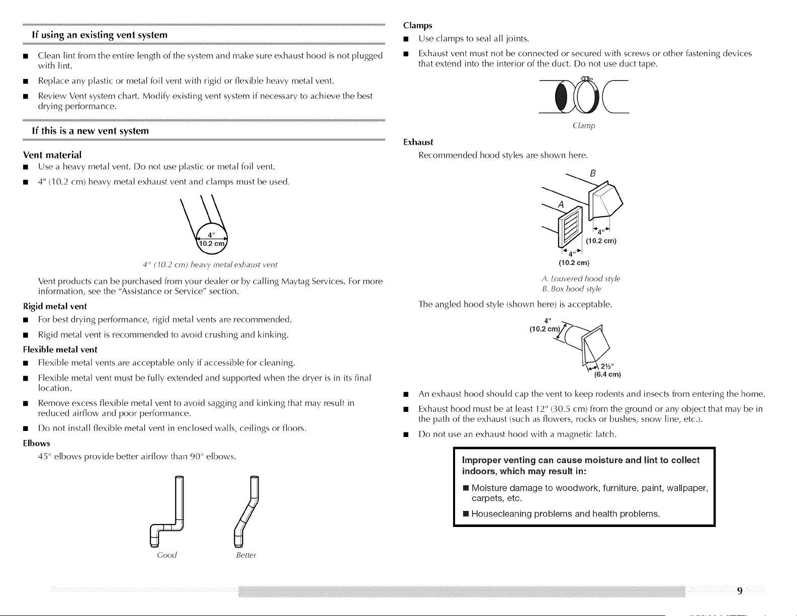
Fire Hazard
Use a heavy metal vent.
Do not use a plastic vent.
Do not use a metal foil vent.
Failure to follow these instructions can result in death
or fire.
WARNING: To reduce the risk of fire, this dryer MUST BE EXHAUSTED OUTDOORS.
IMPORTANT: Observe all governing codes and ordinances.
The dryer exhaust must not be connected into any gas vent, chimney, wall, ceiling, or a
concealed space of a building.
t®TEF[ ON is a registered trademark of E.[. Du Pont De Nemours and Company.
8
If using an existing vent system
Clean lint from the entire length of the system and make sure exhaust hood is not plugged
with [int.
Replace any plastic or metal foil vent with rigid or flexible heavy metal vent.
Review Vent system chart. Modify existing vent system if necessary to achieve the best
drying performance.
If this is a new vent system
Vent material
• Use a heavy metal vent. Do not use plastic or metal foil vent.
• 4" (1 0.2 cm) heavy metal exhaust vent and clamps must be used.
4" ( 10.2 cm) heavy metal exhaust vent
Vent products can be purchased from your dealer or by calling Maytag Services. For more
information, see the "Assistance or Service" section.
Rigid metal vent
• For best drying performance, rigid metal vents are recommended.
• Rigid metal vent is recommended to avoid crushing and kinking.
Flexible metal vent
• Flexible metal vents are acceptable only if accessible for cleaning.
• Flexible metal vent must be fully extended and supported when the dryer is in its final
location.
• Remove excess flexible metal vent to avoid sagging and kinking that may result in
reduced airflow and poor performance.
• Do not install flexible metal vent in enclosed walls, ceilings or floors.
Elbows
45 ° elbows provide better airflow than 90 ° elbows.
Good
Better
Clamps
• Use clamps to seal all joints.
• Exhaust vent must not be connected or secured with screws or other fastening devices
that extend into the interior of the duct. Do not use duct tape.
Clamp
Exhaust
Recommended hood styles are shown here.
(10.2 era)
A. Louvered hood style
B. Box hood style
The angled hood style (shown here) is acceptable.
(6.4 cm)
An exhaust hood should cap the vent to keep rodents and insects from entering the home.
Exhaust hood must be at least 12" (30.5 cm) from the ground or any object that may be in
the path of the exhaust (such as flowers, rocks or bushes, snow line, etc.).
Do not use an exhaust hood with a magnetic latch.
improper venting can cause moisture and lint to collect
indoors, which may result in:
[] Moisture damage to woodwork, furniture, paint, wallpaper,
carpets, etc.
[] Housecleaning problems and health problems.
Choose your exhaust installation type
F
Recommended exhaust installations
Typical installations vent the dryer from the rear of the dryer.
B
i
A. Dryer
B. Elbow
C. Wall
D. Exhaust hood
Optional exhaust installations
E. Clamps
£ Rigid metal or flexible metal vent
C. Vent length necessary to connect elbows
H. fxhaust out]et
Venting systems come in many varieties. Select the type best for your installation.
Fire Hazard
Cover unused exhaust hole with the following kit:
8212503
Contact your local dealer.
Failure to follow these instructions can result in death,
fire, electrical shock, or serious injury.
This dryer can be converted to exhaust out the bottom. If you prefer; you may contact your
local dealer to have the dryer converted.
This dryer can also be exhausted from the rear to either the right or left side. Optional kits for
these exhaust installations are needed. Refer to the manufacturer's instructions for kit
installation instructions.
A B
A. Standard rear offset exhaust instaflation
B. Rear exhaust insta//ation to the right or left side
C D
c. Bottom exhaust instafltion
D. Over-the-top insta//ation (also avai/ab/e with
one offset elbow)
NOTE: The following kits for close clearance alternate installations are available for purchase.
Please see the "Assistance or Service" section to order.
• Over-the-Top Installation:
Part Number 4396028
• Periscope Installation (For use with dryer vent to wall vent mismatch):
Part Number 4396037 - 0" (0 cm) to 18" (45.72 cm) mismatch
Part Number 4396011 - 18" (45.72 cm) to 29" (73.66 cm) mismatch
Part Number 4396014 - 29" (73.66 cm) to 50" (127 cm) mismatch
• Rear exhaust installation to left or right side:
Part Number 4396011
• Vent extension:
Part Number 8544761
• Bottom Exhaust:
Part Number 8212503
| 0
Special provisions for mobile home installations
The exhaust vent must be securely fastened to a noncombustible portion of the mobile home
structure and must not terminate beneath the mobile home. Terminate the exhaust vent
outside.
/I
m
Determine vent path
• Select the route that will provide the straightest and most direct path outdoors.
• Plan the installation to use the fewest number of elbows and turns.
• When using elbows or making turns, allow as much room as possible.
• Bend vent gradually to avoid kinking.
• Use the fewest 90 ° turns possible.
Determine vent length and elbows needed for best drying performance
• Use the following Vent system chart to determine type of vent material and hood
combinations acceptable to use.
NOTE: Do not use vent runs longer than those specified in the Vent system chart.
Exhaust systems longer than those specified will:
• Shorten the life of the dryer.
• Reduce performance, resulting in longer drying times and increased energy usage.
The Vent system chart provides venting requirements that will help to achieve the best drying
performance.
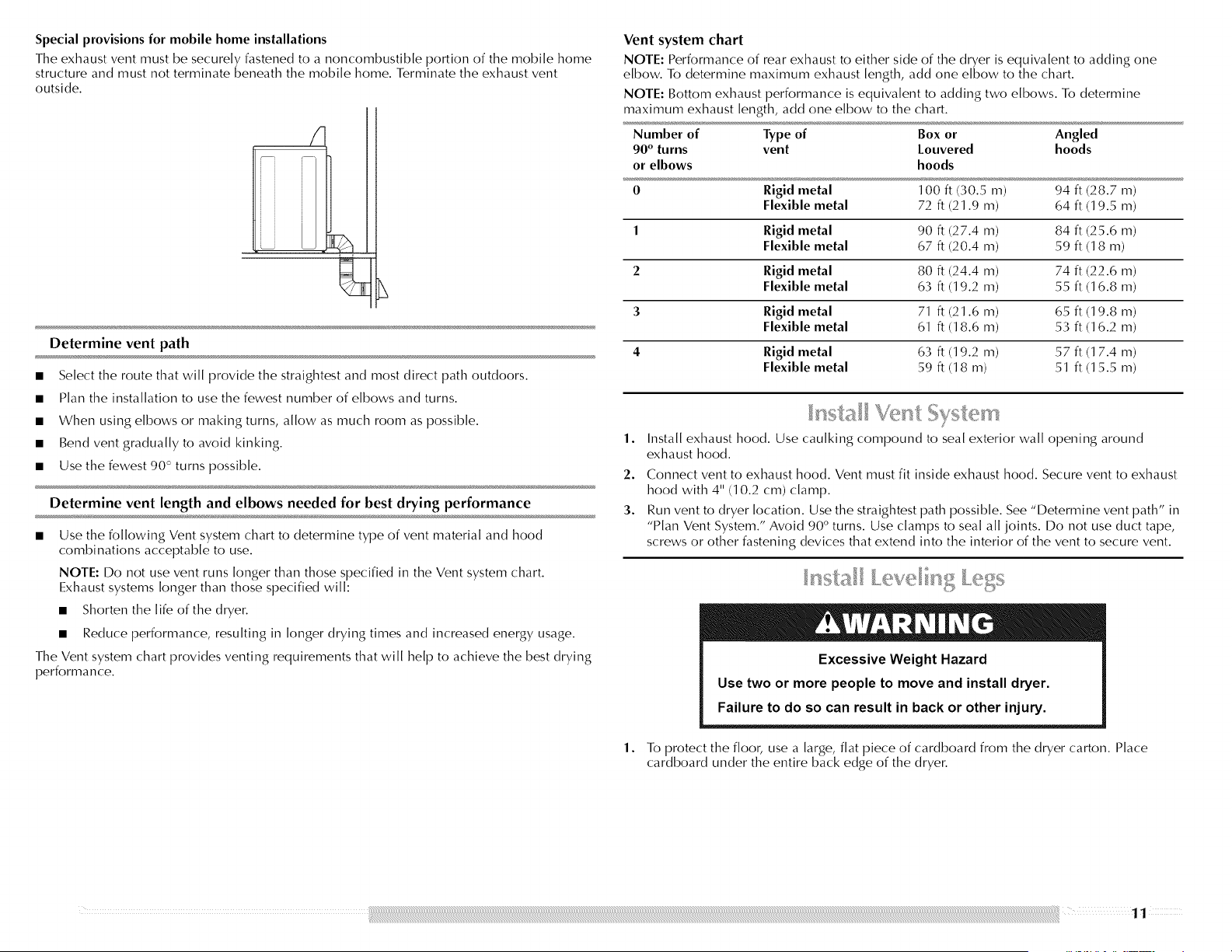
Vent system chart
NOTE: Performance of rear exhaust to either side of the dryer is equivalent to adding one
elbow. To determine maximum exhaust length, add one elbow to the chart.
NOTE: Bottom exhaust performance is equivalent to adding two elbows. To determine
maximum exhaust length, add one elbow to the chart.
Number of Type of Box or Angled
90 ° turns vent Louvered hoods
or elbows hoods
0 Rigid metal 100 ft (30.5 m) 94 ft (28.7 m)
Flexible metal 72 ft (21.9 m) 64 ft (19.5 m)
1 Rigid metal 90 ft (27.4 m) 84 ft (25.6 m)
Flexible metal 67 ft (20.4 m) 59 ft (18 m)
2 Rigid metal 80 ft (24.4 m) 74 ft (22.6 m)
Flexible metal 63 ft (19.2 m) 55 ft (16.8 m)
3 Rigid metal 71 ft (21.6 m) 65 ft (19.8 m)
Flexible metal 61 ft (18.6 m) 53 ft (16.2 m)
4 Rigid metal 63 ft (19.2 m) 57 ft (1 7.4 m)
Flexible metal 59 ft (18 m) 51 ft (15.5 m)
1.
2.
3.
1.
Install exhaust hood. Use caulking compound to seal exterior wall opening around
exhaust hood.
Connect vent to exhaust hood. Vent must fit inside exhaust hood. Secure vent to exhaust
hood with 4" (10.2 cm) clamp.
Run vent to dryer location. Use the straightest path possible. See "Determine vent path" in
"Plan Vent System." Avoid 90 ° turns. Use clamps to seal all joints. Do not use duct tape,
screws or other fastening devices that extend into the interior of the vent to secure vent.
Excessive Weight Hazard
Use two or more people to move and install dryer.
Failure to do so can result in back or other injury.
To protect the floor, use a large, flat piece of cardboard from the dryer carton. Place
cardboard under the entire back edge of the dryer.
2. Firmlygraspthebodyofthedryer(notthetoporconsolepanel).Gentlylaythedryeron
thecardboard.Seeillustration.
3.
Examine the leveling legs. Find the diamond marking.
4. Screw the legs into the leg holes by hand. Use a wrench to finish turning the legs until the
diamond marking is no longer visible.
5. Place a carton corner post from dryer packaging under each of the 2 dryer back corners.
Stand the dryer up. Slide the dryer on the corner posts until it is close to its final location.
I.eave enough room to connect the exhaust vent.
For mobile home use
Gas dryers must be securely fastened to the floor.
Mobile home installations require a Mobile Home Installation Kit. See "Tools and Parts"
section for information on ordering.
1.
2.
Remove the red cap from the gas pipe.
Using a wrench to tighten, connect the gas supply to the dryer. Use pipe-joint compound
on the threads of all non-flared male fittings. If flexible metal tubing is used, be sure there
are no kinks.
A......................................_ ..................................B
A. Flared male thread
B. Non-flared male thread
3.
4.
NOTE: For I.P gas connections, you must use pipe-joint compound resistant to the action
of I.P gas. Do not use TEEI.ON _)+tape.
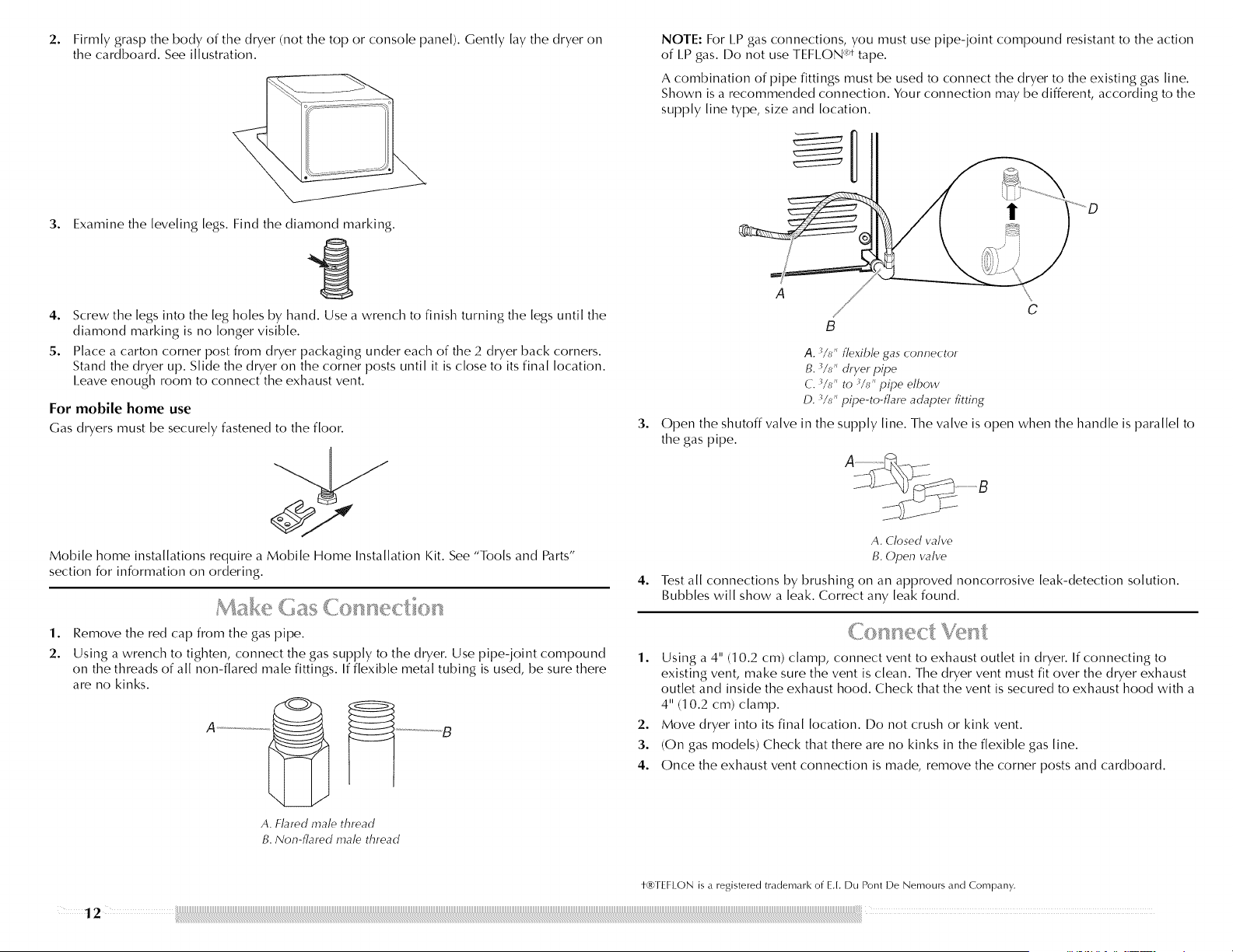
A combination of pipe fittings must be used to connect the dryer to the existing gas line.
Shown is a recommended connection. Your connection may be different, according to the
supply line type, size and location.
!
A
C
B
A. %/' flexible gas connector
B. 3/_,, dryer pipe
C. 3/_,, to _/u" pipe ell)ow
D. 3M/' pipe-to-flare adapter fitting
Open the shutoff valve in the supply line. The valve is open when the handle is parallel to
the gas pipe.
A. Closed valve
B. Open valve
Test all connections by brushing on an approved noncorrosive leak-detection solution.
Bubbles will show a leak. Correct any leak found.
1. Using a 4" (1 0.2 cm) clamp, connect vent to exhaust outlet in dryer. If connecting to
existing vent, make sure the vent is clean. The dryer vent must fit over the dryer exhaust
outlet and inside the exhaust hood. Check that the vent is secured to exhaust hood with a
4" (1 0.2 cm) clamp.
2. Move dryer into its final location. I)o not crush or kink vent.
3. (On gas models) Check that there are no kinks in the flexible gas line.
4. Once the exhaust vent connection is made, remove the corner posts and cardboard.
12
t-_)TEFI (_)N is a registered trademark of E.I. Du Pont De Nemours and Company.
10. Using pliers, tighten the coupling with an additional two-thirds turn.
The dryer must be connected to the cold water faucet using the new inlet hoses. Do not use
old hoses.
1. Turn cold water faucet off and remove washer inlet hose.
2.
3.
4.
Remove old rubber washer from inlet hose and replace with new rubber washer provided.
If space permits, attach the brass female end of the "Y" connector to the cold water faucet.
NOTE: If "Y" connector can be attached directly to cold water faucet, go to Step 6. If "Y"
connector cannot be attached directly to the cold water faucet, the short hose must be
used. Continue with Step 3.
Attach short hose to cold water faucet. Screw on coupling by hand until it is seated on
faucet.
Using pliers, tighten the couplings with an additional two-thirds turn.
NOTE: Do not overtighten. Damage to the coupling can result.
5. Attach "Y" connector to brass male end of small hose. Screw on coupling by hand until it
is seated on connector.
6. Attach straight end of long hose to "Y" connector.
7. Attach washer cold inlet hose to other end of "Y" connector. Screw on coupling by hand
until it is seated on connector.
8. Using pliers, tighten the couplings with an additional two-thirds turn.
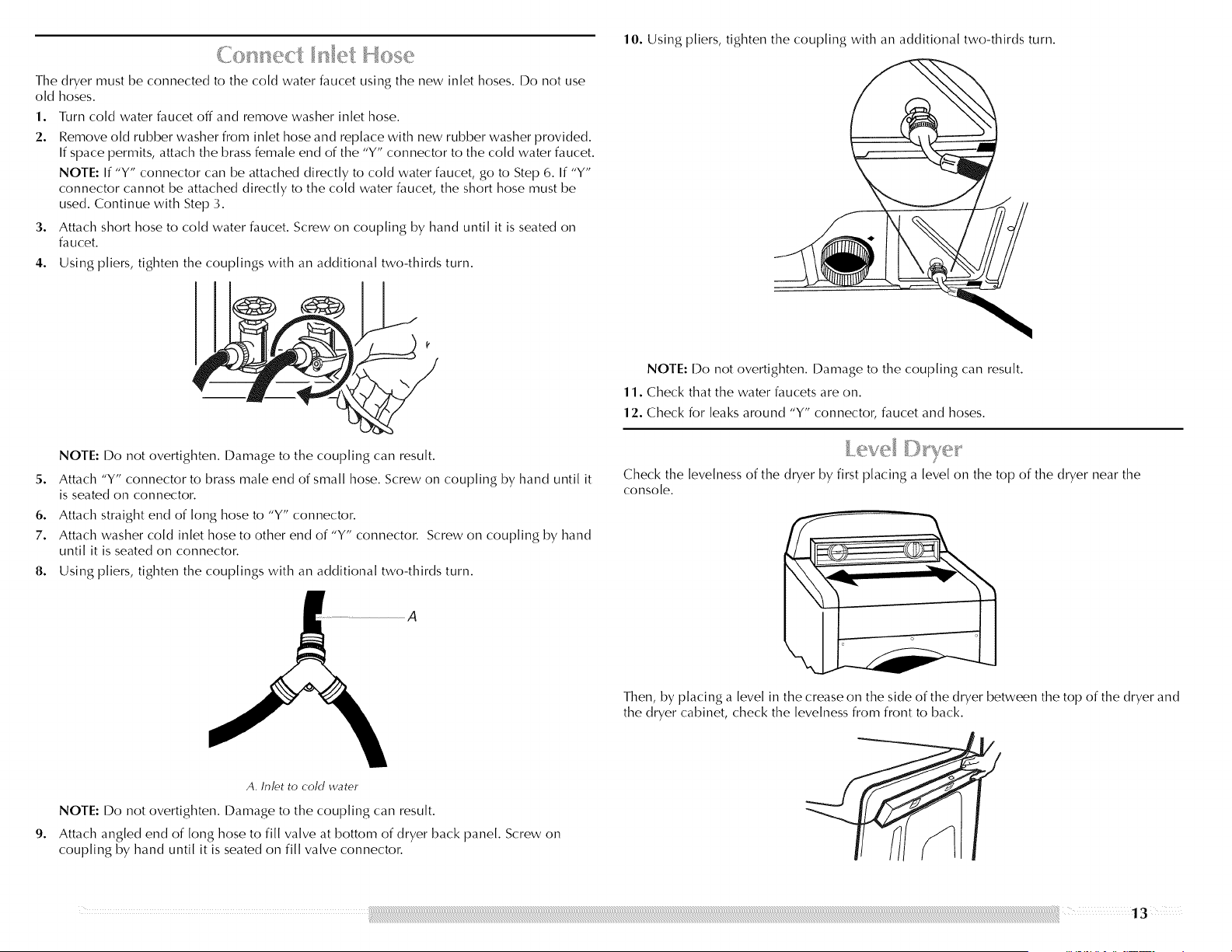
A
NOTE: I)o not overtighten. Damage to the coupling can result.
11. Check that the water faucets are on.
12. Check for leaks around "Y" connector, faucet and hoses.
Check the levelness of the dryer by first placing a level on the top of the dryer near the
console.
Then, by placing a level in the crease on the side of the dryer between the top of the dryer and
the dryer cabinet, check the levelness from front to back.
9.
A. Inlet to cold water
NOTE: Do not overtighten. Damage to the coupling can result.
Attach angled end of long hose to fill valve at bottom of dryer back panel. Screw on
coupling by hand until it is seated on fill valve connector.
Ifthedryerisnotlevel,propupthedryerusingawoodblock.Useawrenchtoadjustthelegs
upordownandcheckagainforlevelness.
5. Removethe4plasticplugslocatedoutsidethedryerdooropening.
Youcanchangeyourdoorswingfromaright-sideopeningtoa left-sideopening,ifdesired.
1. Placeatowelorsoftclothontopofthedryerorworkspacetoprotectthesurface.
Removethedoorassembly
1. Openthedryerdoor.
2. Removethebottomscrewfromeachofthe2 hingesthatattachthedryerdoortothefront
panelofthedryer.
3. I.oosenthetopscrewfromeachofthe2hingesinStep2.
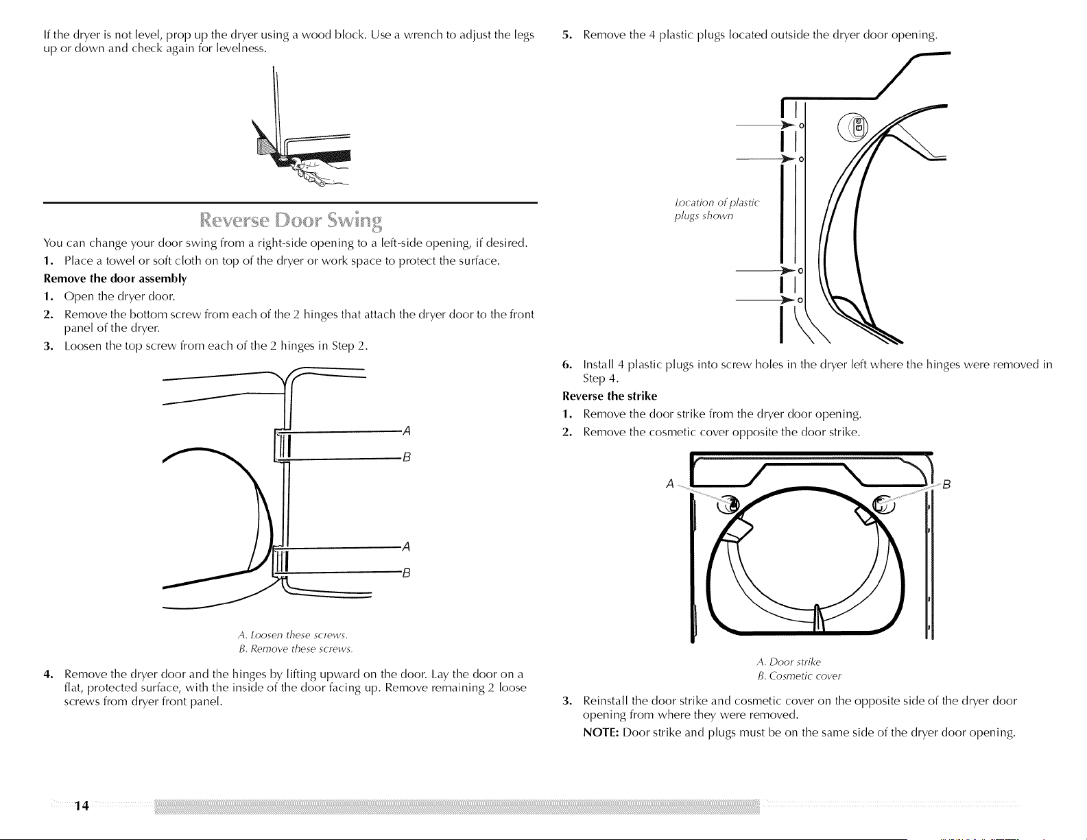
.A
,B
Location of plastic
plugs shown
I
I
6. Install 4 plastic plugs into screw holes in the dryer left where the hinges were removed in
Step 4.
Reverse the strike
1. Remove the door strike from the dryer door opening.
2. Remove the cosmetic cover opposite the door strike.
A
A
"B
4,
A. Loosen these screws.
B. Remove these screws.
Remove the dryer door and the hinges by lifting upward on the door. I.ay the door on a
flat, protected surface, with the inside of the door facing up. Remove remaining 2 loose
screws from dryer front panel.
3,
A. Door strike
B. Cosmetic cover
Reinstall the door strike and cosmetic cover on the opposite side of the dryer door
opening from where they were removed.
NOTE: Door strike and plugs must be on the same side of the dryer door opening.
14
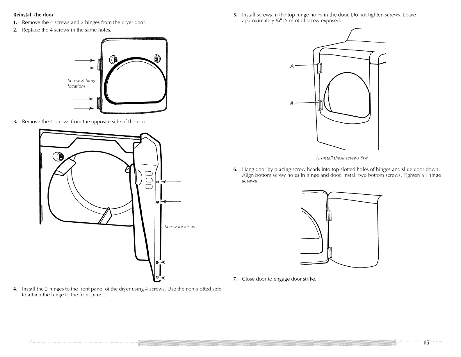
Reinstall the door
1. Remove the 4 screws and 2 hinges from the dryer door.
2. Replace the 4 screws in the same holes.
3o
Screw oR,hinge
locations
Remove the 4 screws from the opposite side of the door.
I
ScFew ]OC_-ItOl°lS
4o
Install the 2 hinges to the front panel of the dryer using 4 screws. Use the non-slotted side
to attach the hinge to the front panel.
5. Install screws in the top hinge holes in the door. Do not tighten screws. I.eave
approximately '/4" (5 mm) of screw exposed.
6o
I
I
f
A. Install these screws first.
Hang door by placing screw heads into top slotted holes of hinges and slide door down.
Align bottom screw holes in hinge and door. Install two bottom screws. Tighten all hinge
screws.
7. Close door to engage door strike.
1. Checkthatallpartsarenowinstalled.Ifthereisanextrapart,gobackthroughthestepsto
seewhichstepwasskipped.
2. Checkthatyouhaveallofyourtools.
3. Disposeof/recycleallpackagingmaterials.
4. Besurethewaterfaucetsareon.
5. Checkforleaksaround"Y"connector,faucetandhoses.
6. Checkthedryer'sfinallocation.Besuretheventisnotcrushedorkinked.
7. Checkthatthedryeris[eve[.See"1eve[Dryer."
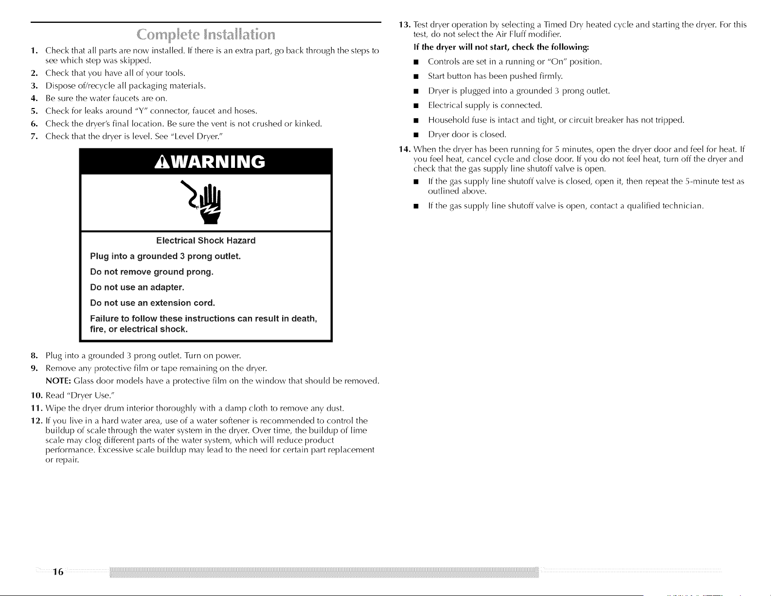
Electrical Shock Hazard
Plug into a grounded 3 prong outlet.
Do not remove ground prong.
Do not use an adapter.
Do not use an extension cord.
Failure to follow these instructions can result in death,
fire, or electrical shock.
13. Test dryer operation by selecting a Timed Dry heated cycle and starting the dryer. For this
test, do not select the Air Fluff modifier.
If the dryer will not start, check the following:
• Controls are set in a running or "On" position.
• Start button has been pushed firmly.
• Dryer is plugged into a grounded 3 prong outlet.
• Electrical supply is connected.
• Household fuse is intact and tight, or circuit breaker has not tripped.
• Dryer door is closed.
14. When the dryer has been running for 5 minutes, open the dryer door and feel for heat. If
you feel heat, cancel cycle and close door. If you do not feel heat, turn off the dryer and
check that the gas supply line shutoff valve is open.
• If the gas supply line shutoff valve is closed, open it, then repeat the 5-minute test as
outlined above.
• If the gas supply line shutoff valve is open, contact a qualified technician.
8. Plug into a grounded 3 prong outlet. Turn on power.
9. Remove any protective film or tape remaining on the dryer.
NOTE: Glass door models have a protective film on the window that should be removed.
10. Read "Dryer Use."
11. Wipe the dryer drum interior thoroughly with a damp cloth to remove any dust.
12. If you live in a hard water area, use of a water softener is recommended to control the
buildup of scale through the water system in the dryer. Over time, the buildup of lime
scale may clog different parts of the water system, which will reduce product
performance. Excessive scale buildup may lead to the need for certain part replacement
or repair.
16
DRYER USE
heavy duty wrinkle control
bltky delicate e d_p
eEess eno,ma_ emote eve_d_less
sensorWde_ a_iu_t_e_sol¸ Wdeo_ty
start
- _Z_ +
w_4 damp co_ d_y wrinkte steam ime ¢ ces s c c es
dow_ prewnt
MAYrAG %:_?_ _,o_]Wo_
_ R AVOS q uiet series/too with steam
Explosion Hazard
Keep flammable materials and vapors, such as
gasoline, away from dryer.
Do not dry anything that has ever had anything
flammable on it (even after washing).
Failure to follow these instructions can result in death,
explosion, or fire.
Fire Hazard
No washer can completely remove oil.
Do not dry anything that has ever had any type of oil on
it (including cooking oils).
Items containing foam, rubber, or plastic must be dried
on a clothesline or by using an Air Cycle.
Failure to follow these instructions can result in death
or fire.
WARNING: To reduce the risk of fire, electric shock, or injury to persons, read the 2.
IMPORTANT SAFETY INSTRUCTIONS before operating this appliance. 3.
This manual covers several different models. Your dryer may not have all of the cycles and 4.
features described.
Follow these basic steps to start your dryer. Please refer to specific sections of this manual for
more detailed information.
1.
Clean lint screen before each load. See "Cleaning the I.int Screen."
NOTE: Your Maytag _'_dryer is equipped with an "Auto Wake-Up" feature. You may also
press any button (except Drum I.ight), turn the knob to select cycle, or open the dryer
door and the display will illuminate. If the dryer is not started within 5 minutes, the dryer
will turn off the display.
Place laundry in dryer and shut door.
Press POWER/CANCEl ....
Turn the knob to the selected cycle. The preset settings for Sensob Timed, or Steam Cycles
will illuminate. The estimated (sensor cycle) or actual (timed) cycle time (in minutes) will
show in the display.
NOTE: A default time is displayed when an automatic cycle is selected. During the first
few minutes of the drying process, the cycle time may automatically vary from the default
time based on the size and fabric type of the load. Toward the end of the drying process,
the estimated time display will adjust again, showing the final drying time.

To use a Sensor Cycle
• Press POWER/CANCEl .....
Turn the knob to desired Sensor Cycle.
Select DRYNESS LEVEl. to adjust how dry you want the load. As the cycle runs, the
control senses the dryness of the load and adjusts the time automatically for the
selected dryness [eve[.
The initial preset temperature is the prefered setting for drying loads of different
garment types listed (see "Sensor Cycles"). If desired, one alternate temperature may
be selected to dry the load on a lower heat setting. The next time the same cycle is
selected, the alternate temperature is remembered and displayed. The original
(default) temperature may be rese[ected. The Delicate and Bulky cycles do not offer
an alternate temperature.
Select the desired Options.
To make changes during a Sensor Cycle:
• Press START/PAUSE.
• Adjust I)ryness I.evel.
B damp Ill (ess
m normal Im more m verydry dryness
ad ust sensor cycle only eve
NOTE: Dryness selections can be made only while using Sensor Cycles.
How the Sensi-Care TM Drying System Works
Moisture-sensing strips and temperature sensors inside the dryer drum monitor how fast
the load is drying, how hot the air should be, and when clothes are dry. The system
automatically stops the cycle to help save time and avoid overdrying.
To use a Timed Cycle
Turn knob to desired Timed Cycle.
Press the TIME ADJUST + (plus) or- (minus) until the desired drying time is displayed.
Press the + (plus) or - (minus) and the time will change by 1-minute intervals. Press
and hold the + (plus) or - (minus) and the time will change by 5-minute intervals.
NOTE: The Time Adjust feature can be used only with the Timed Cycles and the
Custom Refresh cycle.
time
E adjust
• Press TEMP I.EVEI. until the desired temperature illuminates.
ml air fluff 111 extra low @ low ml medium II regu(ar
NOTE: The Temp I.evel feature can be used only with Timed Cycles and the Custom
Refresh cycle.
NOTE: During a Timed Cycle, you can change the settings for Time, Temp, the Wrinkle
Prevent setting, and the End Signal.
5. (OPTIONAl_ STEP) If desired, select OPTIONS. For more details, see "Options."
6. (OPTIONAl. STEP) If desired, press END SIGNAl.. A signal will sound to alert you when a
cycle ends. For more details, see "End SignaL"
7. Press START/PAUSE. Be sure the door is closed.
• If you do not press Start within 5 minutes of selecting the cycle, the dryer
automatically shuts off.
• If you wish to end your drying cycle after pressing Start, press POWER/CANCEl .....
To use a Steam Cycle
• Press POWER/CANCEl .....
Turn the knob to the desired Steam Cycle.
For the Custom Refresh cycle, press the TIME ADJUST + (plus) or - (minus) until the
desired drying time is displayed. Press the + (plus) or - (minus) and the time will
change by 1 -minute intervals. Press and hold the + (plus) or - (minus) and the time
will change by 5-minute intervals.
NOTE: The Time Adjust features can be used only with Timed Cycles and the Custom
Refresh cycle.
time
adjust +
• Press TEMP I.EVEI. until the desired temperature illuminates.
malrfluff m extra low l low mmedium lregu[ar
NOTE: During the Custom Refresh cycle, you can change the settings for Time Adjust and
Temp Adjust. Open the door or press START/PAUSE to pause, or press POWER/CANCEl ....
to cancel a cycle.
To stop or pause your dryer at any time
Open the door or press START/PAUSE. Press POWER/CANCEl. to cancel a cycle.
To restart the dryer
Close the door. Press START/PAUSE until dryer starts.
NOTE: Drying will continue from where the cycle was interrupted if you dose the door and
press Start within 5 minutes. If the cycle is interrupted for more than 5 minutes, the dryer will
shut off. Select new cycle settings before restarting the dryer.
Select the correct cycle and dryness level or temperature for your load. If a Sensor Cycle is
running, the display shows the estimated cycle time when your dryer is automatically sensing
the dryness [eve[ of your load. If a Timed Cycle is running, the display shows the exact
number of minutes remaining in the cycle.
Coo[ Down tumbles the load without heat during the last few minutes of all cycles. Coo[
Down makes the loads easier to handle and reduces wrinkling. The length of the Coo[ Down
depends on the load size and dryness [eve[.
Drying tips
• Follow care [abe[ directions when they are available.
• If desired, add a fabric softener sheet. Follow package instructions.
• To reduce wrinkling, remove the load from the dryer as soon as tumbling stops. This is
especially important for permanent press, knits, and synthetic fabrics.
1 [
• Avoid drying heavy work clothes together with lighter fabrics. This could cause
overdrying of lighter fabrics and lead to increased shrinkage or wrinkling.
Cycle tips
• I])ry most loads using the preset cycle settings.
• Refer to the Sensor, Steam, or Timed Preset Cycle Settings chart (in the "Cycles" section)
for a guide to drying various loads.
I])rying temperature and dryness level are preset when you choose a Sensor I])ry
Cycle. You can select a different dryness [eve[, depending on your load, by pressing
Dryness and choosing More, Normal, I_ess, or Damp. The initial preset temperature is
the preferred setting; however, you may select an alternate drying temperature by
pressing TEMP I_EVEL. Once selected, the new heat setting will be retained until reset
to the initial preset temperature. The Delicate and Bulky cycles do not allow an
alternate temp to be selected.
• If you wish to adjust the cycle length of a Timed Cycle, press TIME ADJUST + (plus) or
- (minus). Adjust the temperature of a Timed Cycle by pressing TEMP I.EVEI. until the
desired temperature is selected.
NOTE: You cannot choose a dryness [eve[ with Timed Cycles.
Follow the progress of your dryer with the drying Status indicator lights.
wet damp coo[ dry wrinkle steam
down prevent
Wet
The Wet light illuminates at the beginning of a Sensor Cycle if a wet item is detected.
• In a Sensor Cycle, if a wet item is not detected after approximately 5 minutes, the dryer
goes directly into Coo[ Down. The Coo[ Down and the Wrinkle Prevent setting indicators
will illuminate, if selected.
• In a Timed Cycle, wet items are not detected. The dryer will continue to run for the length
of time selected, and the Wet light will illuminate. The Damp light will not illuminate.
Damp
The Damp light illuminates in a Sensor Cycle when the laundry is approximately 80% dry.
Damp Dry signal beeps, if selected. See "Options."
Cool Down
The Cool [])own light illuminates during the Cool [])own part of the cycle. I.aundry cools for
ease in handling.
Dry
The Dry light illuminates when the drying cycle is finished. This indicator stays on during the
Wrinkle Prevent Plus setting.
Wrinkle Prevent
The Wrinkle Prevent setting light illuminates when this option is selected. This indicator stays
on during the Wrinkle Prevent setting.
Steam
The steam light illuminates as water is being sprayed into the drum.
Indicator lights
Other indicator lights show Cycle, Modifiers, Options, and Cycle Signal settings selected. The
display shows the estimated or actual time remaining.
Select the drying cycle that matches the type of load you are drying. See Sensor, Steam or
Timed Cycle Settings charts.
normal
heavyd_inkle control
bulky/_'/_ - J,_ elicate
sensor cycles
timed cycles steam cycles
d refresh
"_V/ small load
rapid dry customrefresh
Sensor Cycles
Sensor Cycles allow you to match the cycle to the load you are drying. See the following
Sensor Preset Cycle Settings chart. Each cycle dries certain fabrics at the recommended
temperature. A sensor detects the moisture in the load and automatically adjusts the drying
time for optimal drying. An alternate temperature is se[ectab[e for all cycles with the
exception of the Delicate and Bulky by pressing the TEMP I.EVEI. button.
Bulky
Use this cycle to get medium heat for drying large items that require very long drying times
such as jackets, comforters, and cotton or polyester fiber filled pillows. Rearrange the load
when the Damp Dry signal sounds. This step will aid in the drying process.
Heavy Duty
Use this cycle to get regular heat for heavyweight mixed loads, cottons, and jeans.
Normal
Use this cycle to get medium heat for drying sturdy fabrics such as work clothes and sheets.
Wrinkle Control
Use this cycle to get low heat for drying no-iron fabrics, such as sport shirts, casual business
clothes, and permanent press blends.
Delicate
Use this cycle to get extra-low heat to gently dry items such as lingerie, blouses, or washable
knit fabrics.
Sensor Preset Cycle Settings
Sensor Cycles Load Type Temperature
BULKY Medium
Jackets, comforters, pillows
HEAVY DUTY Regular*
Heavyweight mixed loads, cottons, jeans Medium heat is se[ectab[e as an
alternate temperature.
NORMAL Medium*
Corduroys, work clothes, sheets I.ow heat is se[ectab[e as an
alternate temperature.
WRINKLE CONTROL Low*
Business casual clothes, permanent press, synthetics Extra-low heat is se[ectab[e as
an alternate temperature.
DELICATE Extra-Low
I.ingerie, blouses, washable knit fabrics
*Preferred setting
Steam Cycles
Use Steam Cycles to help smooth out wrinkles from dry items, such as clothes that have been
worn or clothes that have been [eft in the dryer too long. When a Steam Cycle is selected, the
estimated time remaining display shows the actual time remaining in the cycle.
NOTE: Results may vary depending on fabric. 100% cotton garments with wrinkle-free
finish may yield better results than those without.
Use of a fabric softener sheet is not recommended with steam cycles as it may cause
temporary staining on the clothes.
Rapid Refresh Small Load
This cycle is best for smoothing out wrinkles and reducing odors from loads consisting of one
to four dry items of wrinkle-free cotton, cotton-polyester blend, common knits, and synthetic
garments. In this cycle, a small amount of water is sprayed into the dryer drum after several
minutes of tumbling with heat. The dryer will continue to tumble with heat followed by a brief
coo[ down. The heat [eve[ and cycle time are not adjustable.
Custom Refresh
This cycle is best for touching up clothes that have been [eft in the dryer too long. In this
cycle, a small amount of water is sprayed into the dryer drum after several minutes of
tumbling with heat. The dryer will continue to tumble with heat followed by a brief coo[
down. The dry time and temperature can be adjusted for this cycle.
NOTE: Overloading the dryer may not yield the same results.
Steam Preset Cycle Settings
Timed Cycles Default Temperature* Default Time
Load Type (Minutes)*
RAPID REFRESH Small Load Medium 15
CUSTOM REFRESH Medium 20
*Temp I_eve[ and Time Adjust are se[ectab[e only for the Custom Refresh cycle.
NOTE:The Custom Refresh cycle has a minimum dry time of 15 minutes and a maximum
dry time of 40 minutes. Only the Medium and Regular temperature settings can be used
for the Custom Refresh cycle.
Timed Cycles
Use Timed Cycles to select a specific amount of drying time and a drying temperature. When
a Timed Cycle is selected, the Estimated Time Remaining display shows the actual time
remaining in your cycle. You can change the actual time in the cycle by pressing TIME
ADJUST + (plus) or - (minus). See "Changing Cycles, Modifiers, and Options."
NOTE: Timed Cycles may also be used with the drying rack. See "Drying Rack Option."
Timed Dry
Use this cycle to complete drying if items are still damp after a Sensor Cycle. Timed Dry is
also useful for drying heavyweight and bulky items, such as bedspreads, and work clothes.
Lightweight garments, such as exercise wear, can be dried using Timed Dry on a low
temperature setting. Timed Dry can also be used with the drying rack.
Rapid Dry
Use this cycle for dying small loads that need short drying time.
Timed Preset Cycle Settings
Timed Cycles Default
Load Type Temperature
TIMED DRY High
Heavyweight, bulky items, work
clothes
Default Time
(Minutes)
4O
RAPID DRY Regular 23
Small loads
20
Sensor Cycle Modifiers
Use the DRYNESS LEVEl.button to select dryness levels for the Sensor Cycles. Press DRYNESS
I.EVEI. until the desired Dryness setting illuminates.
The preset dryness setting is Normal when a Sensor Cycle is selected. You can select a
different Dryness I_evel, depending on your load, by pressing DRYNESS LEVEl_and choosing
More, Normal, I_ess,or Damp. Selecting More, Normal, I.ess,or Damp automatically adjusts
the Dryness I_evelat which the dryer will shut off. Once a Dryness I.evel is set, it cannot be
changed without stopping the cycle.
The initial preset temperature is the preferred setting for drying clothes; howeveB if desired,
one alternate temperature may be selected to dry the load on a lower heat setting. Once the
alternate temperature has been selected, the next time the same cycle is selected, the
alternate temperature is remembered and displayed. The original (default) temperature may
be reselected. The Delicate and Bulky cycles do not offer an alternate temperature.
III damp lless m normal Imare III very dry dryn,ess ]
adjust sensor cycle only
NOTE: I)ryness Level selections cannot be used with the Timed or Steam Cycles.
Timed Cycle Modifiers
Use the TEMP LEVEl_ button to select temperatures for the Timed Cycles. Press TEMP I.EVEI....
until the desired temperature setting illuminates.
air fluff a exlra low m low | medium I regular
Air Fluff
Use the Air Fluff Modifier for items that require drying without heat such as rubbeb plastic,
and heat-sensitive fabrics. This table shows examples of items that can be dried using Air
Huff.
Type of Load Time*
(Minutes)
Foam rubber - pillows, padded bras, stuffed toys 20 - 30
Plastic - Shower curtains, tablecloths 20 - 30
Rubber-backed rugs 40 - 50
O[efin, po[ypropy[ene, sheer nylon 10 - 20
*Reset cycle to complete drying, if needed.
When using Air Fluff
• Check that coverings are securely stitched.
• Shake and fluff pillows by hand periodically during the cycle.
• Dry item completely. Foam rubber pillows are slow to dry.
NOTE: Air Fluff is not available with Sensor Cycles.
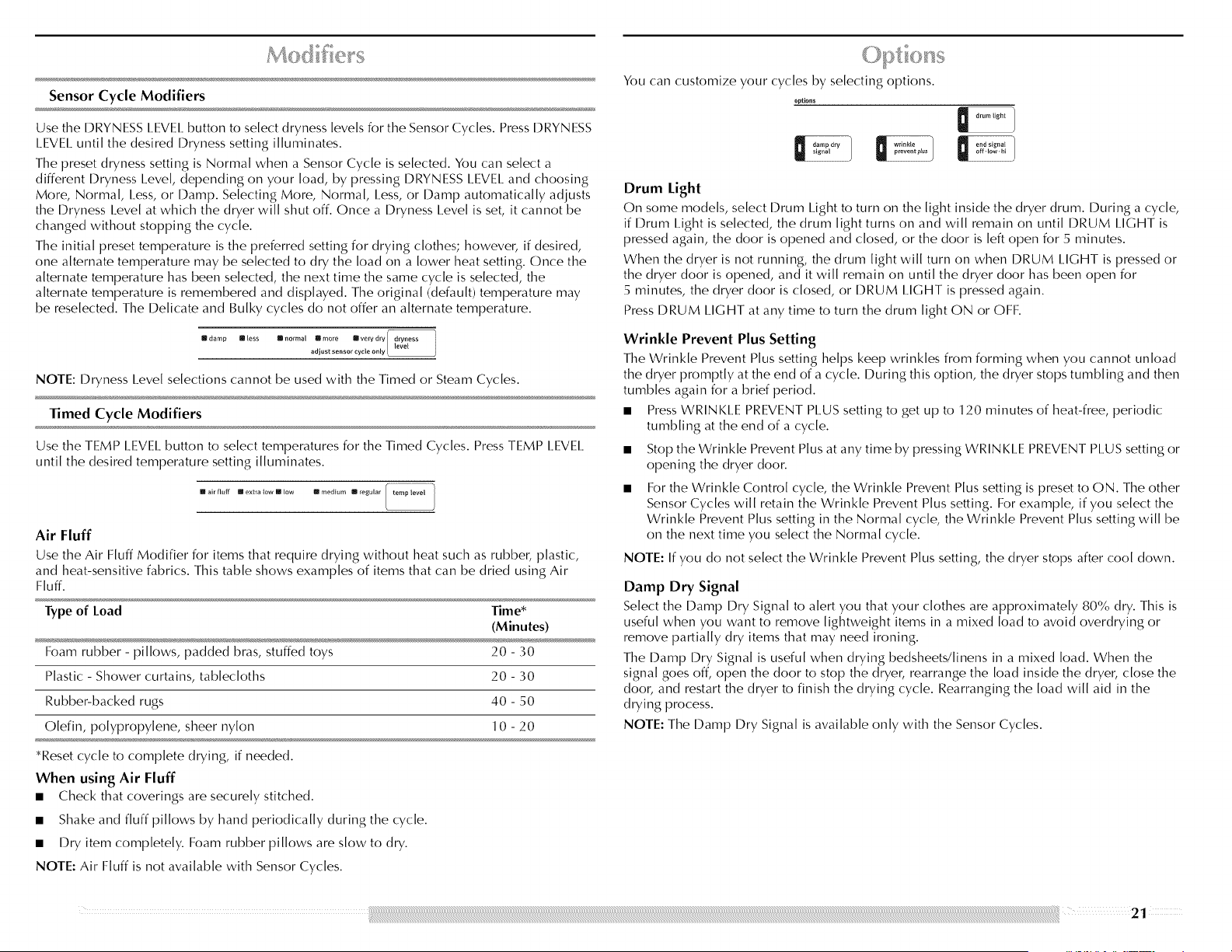
You can customize your cycles by selecting options.
options
Drum Light
On some models, select Drum I.ight to turn on the light inside the dryer drum. During a cycle,
if Drum Light is selected, the drum light turns on and will remain on until DRUM LIGHT is
pressed again, the door is opened and dosed, or the door is [eft open for 5 minutes.
When the dryer is not running, the drum light will turn on when DRUM LIGHT is pressed or
the dryer door is opened, and it will remain on until the dryer door has been open for
5 minutes, the dryer door is dosed, or DRUM I.IGHT is pressed again.
Press DRUM I.IGHT at any time to turn the drum light ON or OFF.
Wrinkle Prevent Plus Setting
The Wrinkle Prevent Plus setting helps keep wrinkles from forming when you cannot unload
the dryer promptly at the end of a cycle. During this option, the dryer stops tumbling and then
tumbles again for a brief period.
• Press WRINKI.E PREVENT PLUS setting to get up to 120 minutes of heat-free, periodic
tumbling at the end of a cycle.
Stop the Wrinkle Prevent Plus at any time by pressing WRINKI.E PREVENT PI.US setting or
opening the dryer door.
For the Wrinkle Control cycle, the Wrinkle Prevent Plus setting is preset to ON. The other
Sensor Cycles will retain the Wrinkle Prevent Plus setting. For example, if you select the
Wrinkle Prevent Plus setting in the Normal cycle, the Wrinkle Prevent Plus setting will be
on the next time you select the Normal cycle.
NOTE: If you do not select the Wrinkle Prevent Plus setting, the dryer stops after cool down.
Damp Dry Signal
Select the Damp Dry Signal to alert you that your clothes are approximately 80% dry. This is
useful when you want to remove lightweight items in a mixed load to avoid overdrying or
remove partially dry items that may need ironing.
The Damp Dry Signal is useful when drying bedsheets/[inens in a mixed load. When the
signal goes off, open the door to stop the dryer, rearrange the load inside the dryer, dose the
door, and restart the dryer to finish the drying cycle. Rearranging the load will aid in the
drying process.
NOTE: The Damp Dry Signal is available only with the Sensor Cycles.
l:; l.i A °* _,
End Signal
The End Signal produces an audible sound when the drying cycle is finished. Promptly
removing clothes at the end of the cycle reduces wrinkling.
Press ENID SIGNAl. until the desired volume (High, I.ow, or Off) is selected.
D nd sifnal 1
off.low.hi
NOTE: When the Wrinkle Prevent Plus setting is selected and the End Signal is on, the tone
will sound every 5 minutes until the clothes are removed, or the Wrinkle Prevent Plus setting
ends.
You can change Sensor and Timed Cycles, Modifiers, and Options anytime before pressing
Start.
• Three short tones sound if an unavailable combination is selected. The last selection will
not be accepted.
Changing Cycles after pressing Start
1. Press POWER/CANCEl .....
2. Select the desired cycle and options.
3. Press START/PAUSE. The dryer starts at the beginning of the new cycle.
NOTE: If you do not press Start/Pause within 5 minutes of selecting the cycle, the dryer
automatically shuts off.
Changing Modifiers and Options after pressing Start
You can change an Option or Modifier anytime before the selected Option or Modifier
begins.
1. Press START/PAUSE.
2. Select the new Option and/or Modifier.
3. Press START/PAUSE to continue the cycle.
Changing the Preset Dryness Level Settings
If all of your loads on all Sensor cycles are consistently not as dry as you would like, you may
change the preset Dryness I.eve[ settings to increase the dryness. This change will affect all of
your Sensor cycles.
Your Dryness I.eve[ settings can be adjusted to adapt to different installations, environmental
conditions, or personal preference. There are 3 drying settings: 1 (factory preset dryness
[eve[), 2 (slightly dryer clothes, approximately 15% more drying time), and 3 (much dryer
clothes, approximately 30% more drying time).
1. The Dryness I.eve[ settings cannot be changed while the dryer is running.
2. Press and hold the DRYNESS LEVEl_ button for 5 seconds. The dryer will beep, and "CF"
will be displayed for 1 second followed by the current Dryness I_eve[ setting.
3. To select a new Dryness I_eve[ setting, press the DRYNESS I.EVEI. button again until the
desired Dryness I.eve[ setting is shown.
4. NOTE: While cycling through the settings, the current setting will not flash, but the other
settings will flash.
" _ ' _ <.+ ¢=.P +J =I J I
II ° .....
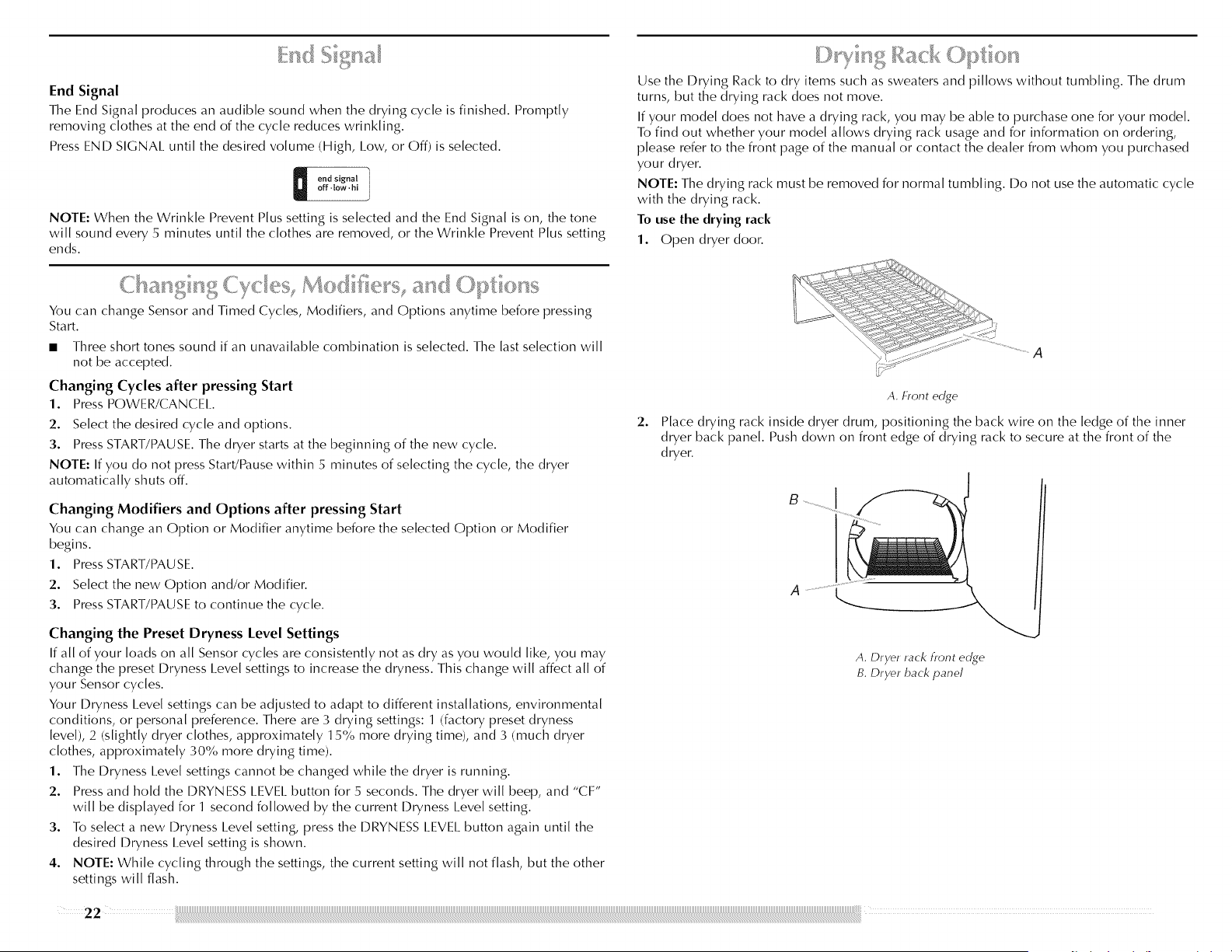
Use the I)rying Rack to dry items such as sweaters and pillows without tumbling. The drum
turns, but the drying rack does not move.
If your modem does not have a drying rack, you may be able to purchase one for your modem.
To find out whether your modem allows drying rack usage and for information on ordering,
please refer to the front page of the manual or contact the dealer from whom you purchased
your dryer.
NOTE: The drying rack must be removed for normal tumbling. 19o not use the automatic cycle
with the drying rack.
To use the drying rack
1. Open dryer door.
\ \_<IJR<<] %<_ :I_-- ]
2.
A. hont edge
Place drying rack inside dryer drum, positioning the back wire on the ledge of the inner
dryer back panel. Push down on front edge of drying rack to secure at the front of the
dryer.
I
A. Dryer rack hont edge
B. Dryer back panel
22 _iii _
3. Put the wet items on top of the drying rack. I.eave space between the items so air can
reach all the surfaces.
NOTE: Do not allow items to hang over the edge of the drying rack.
I
7. You must select a time by pressing TIME ADJUST + (plus) or- (minus). Reset time as
needed to complete drying. Refer to the following table.
8. Press START/PAUSE.
This chart shows examples of items that can be rack dried and the suggested cycle,
temperature setting, and drying time. Actual drying time will depend on the amount of
moisture items hold.
Rack Dry Setting Temp. Time*
(minutes)
4. Close the doon
5. Press the POWER/CANCEl. button.
6. Select a Timed Dry cycle and temperature (see following chart). Items containing foam,
rubber, or plastic must be dried on a clothesline or by using the Air Fluff temperature
setting.
Wool Sweaters Timed Dry I.ow 60
Block to shape and lay flat on the drying rack.
Stuffed toys or pillows Timed Dry I.ow 60
Cotton o r po [yester fiber fi lied
Stuffed toys or pillows Timed Dry Air Fluff 90
Foam rubber filled (no heat)
Sneakers or canvas shoes Timed Dry Air Fluff 90
(no heat)
*Reset time to complete drying, if needed.
DRYER CARE
......... <:_1
Keep dryer area clear and free from items that would obstruct the flow of combustion and
ventilation air.
Explosion Hazard
Keep flammable materials and vapors, such as
gasoline, away from dryer.
Place dryer at least 18 inches (46 cm) above the floor
for a garage installation.
Failure to do so can result in death, explosion, or fire.
<9 .........
Clean the lintscreen before each load.The controlpanel has an indicatorlightto remind you
to clean the lintscreen before each load. A screen blocked by lintcan increase drying time.
IMPORTANT:
• Do not run the dryer with the lint screen loose, damaged, blocked, or missing. Doing so
can cause overheating and damage to both the dryer and fabrics.
• If lint falls off the screen into the dryer during removal, check the exhaust hood and
remove the lint.
Every load cleaning
1.
The lint screen is located in the door opening of the dryer. Pull the lint screen straight up.
Roll lint off the screen with your fingers. Do not rinse or wash screen to remove lint. Wet
lint is hard to remove.
2. Push the lint screen firmly back into place.
As needed cleaning Non-Use or Vacation Care
I.aundry detergent and fabric softener residue can build up on the lint screen. This buildup
can cause longer drying times for your clothes, or cause the dryer to stop before your load is
completely dry. The screen is probably clogged if lint falls off while the screen is in the dryer.
Clean the lint screen with a nylon brush every 6 months, or more frequently, if it becomes
clogged due to a residue buildup.
To wash
1. Roll lint off screen with your fingers.
2. Wet both sides of lint screen with hot water.
3. Wet a nylon brush with hot water and liquid detergent Scrub lint screen with the brush to
remove residue buildup.
4. Rinse screen with hot water.
5. Thoroughly dry lint screen with a clean towel. Replace screen in dryer.
1. Apply a liquid, nonflammable household cleaner to the stained area of the drum and rub
with a soft cloth until stain is removed.
2. Wipe drum thoroughly with a damp cloth.
3. Tumble a load of clean cloths or towels to dry the drum.
NOTE: Garments that contain unstable dyes, such as denim blue jeans or brightly colored
cotton items, may discolor the dryer interior. These stains are not harmful to your dryer and
will not stain future loads of clothes. Dry unstable dye items inside out to avoid transfer of
dye.
From Inside the Dryer Cabinet
I.int should be removed every 2 years, or more often, depending on dryer usage. Cleaning
should be done by a qualified person.
From the Exhaust Vent
I.int should be removed every 2 years, or more often, depending on dryer usage.
Replace inlet hoses and hose screen after 5 years of use to reduce the risk of hose failure.
Periodically inspect and replace inlet hoses if bulges, kinks, cuts, wear, or leaks are found.
When replacing your inlet hoses, record the date of replacement
Install and store your dryer where it will not freeze. Because some water may stay in the
hoses, freezing can damage your dryer. If storing or moving your dryer during freezing
weather; winterize it.
Operate your dryer only when you are at home. If you will be on vacation or not using your
dryer for an extended period of time, you should:
1. Unplug dryer or disconnect power.
2. Close shutoff valve in gas supply line
3. Clean lint screen. See "Cleaning the I.int Screen."
4. Turn off the water supply to the dryer. This helps to avoid unintended flooding (due to a
water pressure surge) while you are away.
To winterize dryer
1. Unplug dryer or disconnect power.
2. Shut off water faucet.
3. I)isconnect water inlet hose from faucet and drain.
4. Close shutoff valve in gas supply line.
To use dryer again
1. Flush water pipes. Reconnect water inlet hose to faucet Turn on water faucet
2. Plug in dryer or reconnect power.
3. Open shutoff valve in gas supply line.
Moving care
For power supply cord-connected dryers:
1. Unplug the power supply cord.
2. Shut off water faucet.
3. Disconnect the water inlet hose from faucet, then drain the hose. Transport hose
separately.
4. Close shutoff valve in gas supply line.
5. Disconnect gas supply line pipe and remove fittings attached to dryer pipe.
6. Cap the open fuel supply line.
7. Make sure leveling legs are secure in dryer base.
8. Use masking tape to secure dryer door.
Reinstalling the dryer
Follow the "Installation Instructions" to locate, level, and connect the dryer.
The dryer light automatically turns on inside the dryer drum when you open the door.
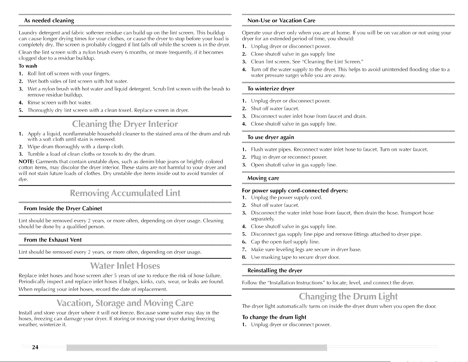
To change the drum light
1. Unplug dryer or disconnect power.
2 4
2. Open the dryer door. I_ocate the light bulb cover on the back wall of the dryer. Remove
the screw located in the lower right corner of the cover. Remove the cover.
3. Turn bulb counterclockwise. Replace the bulb with a 10-watt appliance bulb only.
Replace the cover and secure with the screw.
4. Plug in dryer or reconnect power.
First try the solutions suggested here or visit our website and reference FAQs (Frequently Asked Questions)
to possibly avoid the cost of a service call...
In U.S.A. www.maytag.com/help - In Canada www.maytag.ca
Dryer will not run •
• Has a household fuse blown, or has a circuit breaker tripped? •
Replace the fuse or reset the circuit breaker. If the problem continues, call an electrician.
• Was a regular fuse used? •
Use a time-delay fuse.
• Is the dryer door firmly closed?
• Was the Start/Pause button firmly pressed?
I_arge loads may require pressing and holding the Start/Pause button for 2-5 seconds.
No heat
• Has a household fuse blown, or has a circuit breaker tripped?
The drum may be turning, but you may not have heat. Replace the fuse or reset the circuit
breaker. If the problem continues, ca[[ an electrician.
Unusual sounds
Is a coin, button or paper clip caught between the drum and front or rear of the dryer?
Check the front and rear edges of the drum for small objects. Clean out pockets before
laundering.
Is it a gas dryer?
The gas valve clicking is a normal operating sound.
Are the four legs installed, and is the dryer level front to back and side to side?
The dryer may vibrate if not properly installed. See the Installation Instructions.
Is the clothing knotted or balled up?
When balled up, the load will bounce, causing the dryer to vibrate. Separate the load
items and restart the dryer.
Dryer displaying code message
"PF" (power failure), check the following:
Was the drying cycle interrupted by a power failure?
Depending on the length of the power outage, you may be able to resume the cycle by
simply pressing START/PAUSE; otherwise, press POWER/CANCEl. and then start a new
drying cycle.
• "F" Variable (F1, F2, F20, etc.) service codes:
Call for service.
• Has the dryer had a period of non-use?
If the dryer hasn't been used for a while, there may be a thumping sound during the first
few minutes of operation.

Clothes are not drying satisfactorily, drying times are too long, or load is too hot
Is the lint screen clogged with lint?
I.int screen should be cleaned before each load.
Fire Hazard
Use a heavy metal vent.
Do not use a plastic vent.
Do not use a metal foil vent.
Failure to follow these instructions can result in death
or fire.
Is the exhaust vent or outside exhaust hood clogged with lint, restricting air movement?
Run the dryer for 5-1 0 minutes. Hold your hand under the outside exhaust hood to check
air movement. If you do not fee[ air movement, clean exhaust system of lint or replace
exhaust vent with heavy metal or flexible metal vent. See the Installation Instructions.
Are fabric softener sheets blocking the grille?
Use only one fabric softener sheet, and use it only once.
Is the exhaust vent the correct length?
Check that the exhaust vent is not too long or has too many turns. I.ong venting will
increase drying times. See the Installation Instructions.
Is the exhaust vent diameter the correct size?
Use 4" (1 0.2 cm) diameter vent material.
Explosion Hazard
Keep flammable materials and vapors, such as
gasoline, away from dryer.
Place dryer at least 18 inches (46 cm) above the floor
for a garage installation.
Failure to do so can result in death, explosion, or fire.
Is the dryer located in a room with temperature below 45°F (7°C)?
Proper operation of dryer cycles requires temperatures above 45°F (7°C).
Is the dryer located in a closet?
Closet doors must have ventilation openings at the top and bottom of the door. The rear of
the dryer requires 5" (12.7 cm) of airspace, and the sides and front of the dryer require a
minimum of 1" (2.5 cm). See the Installation Instructions.
Has the Air Fluff modifier been selected?
Select the right temperature for the types of garments being dried. See "Modifiers."
Is the load too large and heavy to dry quickly?
Separate the load to tumble freely.
Are clothes coming out of the Rapid Refresh Small Load cycle with damp or wet spots?
Under certain environmental or installation conditions, you may experience underdrying.
Select the CUSTOM REFRESH cycle (20 min. default time), which can be customized by
selecting the temperature by pressing TEMP I.EVEI. and/or cycle time by pressing the TIME
ADJUST + (plus) or - (minus).
Cycle time too short
Excessive Weight Hazard
Use two or more people to move and install dryer.
Failure to do so can result in back or other injury.
Is the automatic cycle ending early?
The load may not be contacting the sensor strips. I.evel the dryer.
Change the dryness [eve[ setting on Sensor Cycles. Increasing or decreasing the dryness
[eve[ will change the amount of drying time in a cycle.
Lint on load
• Is the lint screen clogged?
Clean lint screen. Check for air movement.
Stains on load or drum
• Was dryer fabric softener properly used?
Add dryer fabric softener sheets at the beginning of the cycle. Fabric softener sheets added
to a partially dried load can stain your garments.
I)rum stains are caused by dyes in clothing (usually blue jeans). This will not transfer to
other clothing.
Loads are wrinkled
Was the load removed from dryer at the end of the cycle?
Select Custom Refresh cycle to tumble the load with water and heat to help smooth out
wrinkles from a load [eft in the dryer.
Was the dryer overloaded?
Dry smaller loads that can tumble freely. Smaller loads yield best results with the Rapid
Refresh Small I.oad cycle. Results may also vary depending on fabric type. This cycle is
best for reducing wrinkles and odors from loads consisting of wrinkle-free cotton, cotton
polyester blends, common knits, and synthetics.
Loads are still wrinkled following Steam cycles?
Make sure water is connected to the dryer. Check that water inlet hose is connected to
both the faucet and dryer's water inlet valve. Check that the water supply is turned on.
These cycles are best for smoothing out wrinkles and reducing odors from loads
consisting of wrinkle-free cotton, cotton polyester blends, common knits, and synthetic
garments.
NOTE: Refer to garment care label instructions. I)ry clean only garments are not
recommended.
Odors
Have you recently been painting, staining, or varnishing in the area where your dryer is
located?
If so, ventilate the area. When the odors or fumes are gone from the area, rewash and dry
the clothing.
Is water connected to the dryer?
Check that water inlet hose is connected to both the faucet and dryer's water inlet valve.
Check that the water supply is turned on.
To remove odors left in garments after wearing, select the Rapid Refresh Small I_oad cycle
for small loads of two to four garments. This cycle is best for reducing wrinkles and odors
from loads consisting of wrinkle-free cotton, cotton polyester blends, common knits, and
synthetics.
Beforecallingforassistanceorservice,pleasecheck"Troubleshooting."Itmaysaveyouthe
costofaserviceca[[.Ifyoustillneedhelp,followtheinstructionsbelow.
Whencalling,pleaseknowthepurchasedateandthecompletemode[andserialnumberof
yourappliance.Thisinformationwillhelpustobetterrespondtoyourrequest.
If you need replacement parts
If you need to order replacement parts, we recommend that you use only factory specified
parts. Factory specified parts will fit right and work right because they are made with the same
precision used to build every new MAYTAG <_appliance.
To locate factory specified parts in your area, ca[[ the following customer assistance telephone
number or your nearest designated service center.
iii I,.9÷>.I÷ £.
CaI[ the WhMpoo[ Canada I_PCustomer eXperience Centre toil free: 1-800-807-6777, or visit
our website www.maytag.ca..
Our consultants provide assistance with:
• Features and specifications on our full line of appliances.
• Use and maintenance procedures.
• Accessory and repair parts sales.
• Referrals to local dealers, repair parts distributors, and service companies. Whirlpool
Canada I_Pdesignated service technicians are trained to fulfill the product warranty and
provide after-warranty service, anywhere in Canada.
Ca[[ Maytag Services, I.I.C Customer Assistance to[[ free: 1-800-688-9900, or vist our website
at www.maytag.com
Our consultants provide assistance with:
• Features and specifications on our full line of appliances.
• Installation information.
• Use and maintenance procedures.
• Accessory and repair parts sales.
• Specialized customer assistance (Spanish speaking, hearing impaired, limited vision,
etc.).
• Referrals to local dealers, repair parts distributors and service companies. Maytag <'>
appliances designated service technicians are trained to fulfill the product warranty and
provide after-warranty service, anywhere in the United States.
To locate the Maytag <'>appliances designated service company in your area, you can also
look in your telephone directory Yellow Pages.
For further assistance
If you need further assistance, you can write to Maytag <_>appliances with any questions or
concerns at:
Maytag Services, I.I_C
ATTN: CAIR _k_Center
RO. Box 2370
Cleveland, TN 37320-2370
Please include a daytime phone number in your correspondence.
For further assistance
If you need further assistance, you can write to Whirlpool Canada I.P with any questions or
concerns at:
Customer eXperience Centre
Whirlpool Canada I_P
1901 Minnesota Court
Mississauga, Ontario 1.5N 3A7
Please include a daytime phone number in your correspondence.
[
ACCESSORIES
Enhance your dryer with these premium accessories.
For more high-quality items or to ordeD ca[[ 1-800-901-2042, or visit us at
www.maytag.com/accessories. In Canada, ca[[ 1-800-807-6777, or visit us at
www.maytag.ca.
Part Number
20-48KITRC
PT2201 ....
PT4001 ....
PT6001 ....
8212614
31682
1903WH
49572
8577312
W10044609A
4 ft (1.2 m) gas line dryer connector installation kit
4 ft (1.2 m) dryer cord, 3-wire, 30 amp
4 ft (1.2 m) dryer cord, 4-wire, 30 amp
6 ft (1.8 m) dryer cord, 4-wire, 30 amp
Dryer vent lint brush
All-purpose appliance cleaner
I.aundry supply storage cart
I.P Gas conversion kit
Drying rack
Steam hose kit
28

LIMITED WARRANTY
For one year from the date of purchase, when this major appliance is operated and maintained according to instructions attached to or furnished with the product, Maytag brand of Whirlpool
Corporation or Whirlpool Canada I P (hereafter "Maytag") will pay for factory specified parts and repair labor to correct defects in materials or workmanship. Service must be provided by a
Maytag designated service company. This limited warranty is valid only in the United States or Canada and applies only when the major appliance is used in the country in which it was
purchased. Outside the 50 United States and Canada, this limited warranty does not apply. Proof of original purchase date is required to obtain service under this limited warranty.
ITEMS EXCLUDED FROM WARRANTY
This limited warranty does not cover:
1. Service calls to correct the installation of your major appliance, to instruct you on how to use your major appliance, to replace or repair house fuses, or to correct house wiring or plumbing.
2. Service calls to repair or replace appliance light bulbs, air filters or water filters. Consumable parts are excluded from warranty coverage.
3. Repairs when your major appliance is used for other than normal, single-family household use or when it is used in a manner that is contrary to published user or operator instructions and/
or installation instructions.
4. Damage resulting from accident, alteration, misuse, abuse, fire, flood, acts of God, improper installation, installation not in accordance with electrical or plumbing codes, or use of
consumables or cleaning products not approved by Maytag.
5. Cosmetic damage, including scratches, dents, chips or other damage to the finish of your major appliance, unless such damage results from defects in materials or workmanship and is
reported to Maytag within 30 days from the date of purchase.
6. Any food loss due to refrigerator or freezer product failures.
7. Costs associated with the removal from your home of your major appliance for repairs. This major appliance is designed to be repaired in the home and only in-home service is covered by
this warranty.
8. Repairs to parts or systems resulting from unauthorized modifications made to the appliance.
9. Expenses for travel and transportation for product service if your major appliance is located in a remote area where service by an authorized Maytag servicer is not available.
10. The removal and reinsta[[ation of your major appliance if it is installed in an inaccessible location or is not installed in accordance with published installation instructions.
11. Major appliances with original model/serial numbers that have been removed, altered or cannot be easily determined. This warranty is void if the factory applied serial number has been
altered or removed from your major appliance.
The cost of repair or replacement under these excluded circumstances shall be borne by the customer.
DISCLAIMER OF IMPLIED WARRANTIES; LIMITATION OF REMEDIES
CUSTOMER'S SOLE AND EXCI.USIVE REMEDY UNDER THIS I_IMITED WARRANTY SHAH_ BE PRODUCT REPAIR AS PROVIDED HEREIN. IMPHEI) WARRANTIES, INCI.UDING
WARRANTIES OF MERCHANTABILITY OR FITNESS FOR A PARTICUI_AR PURPOSE, ARE I_IMITED TO ONE YEAR OR THE SHORTEST PERIOD AI_I_OWEI) BY I_AW. MAYTAG SHALL NOT BE
I.IAB LE FOR INCI DENTAl_ OR CONSEQU ENTIAI_ DAMAG ES. SOM E STATES AN I) PROVINCES I)O NOT ALLOW TH E EXCI.USION OR HMITATION OF INCI DENTAl_ OR CONSEQU ENTIAI_
DAMAGES, OR I.IMITATIONS ON THE DURATION OF IMPHEI) WARRANTIES OF MERCHANTABILITY OR FITNESS, SO THESE EXCI_USIONS OR I_IMITATIONS MAY NOT APPI.Y TO YOU.
THIS WARRANTY GIVES YOU SPECIFIC I.EGAI. RIGHTS, AND YOU MAY AI.SO HAVE OTHER RIGHTS WHICH VARY FROM STATE TO STATE OR PROVINCE TO PROVINCE.
If outside the 50 United States and Canada, contact your authorized Maytag dealer to determine if another warranty applies.
If you need service, first see the "Troubleshooting" section of the Use & Care Guide. After checking "Troubleshooting," you may find additional help by checking the "Assistance or Service"
section or by calling Maytag. In the U.S.A., call 1-800-688-9900. In Canada, call 1-800-807-6777.
9/07
Keep this book and your sales slip together for future reference. You must provide proof of
purchase or installation date for ,'n-warranty service.
Write down the following information about your major appliance to better help you obtain
assistance or service if you ever need it. You will need to know your complete model number
and serial number. You can find this information on the model and serial number label
located on the product.
Dealer name
Address
Phone number
Model number
Serial number
Purchase date
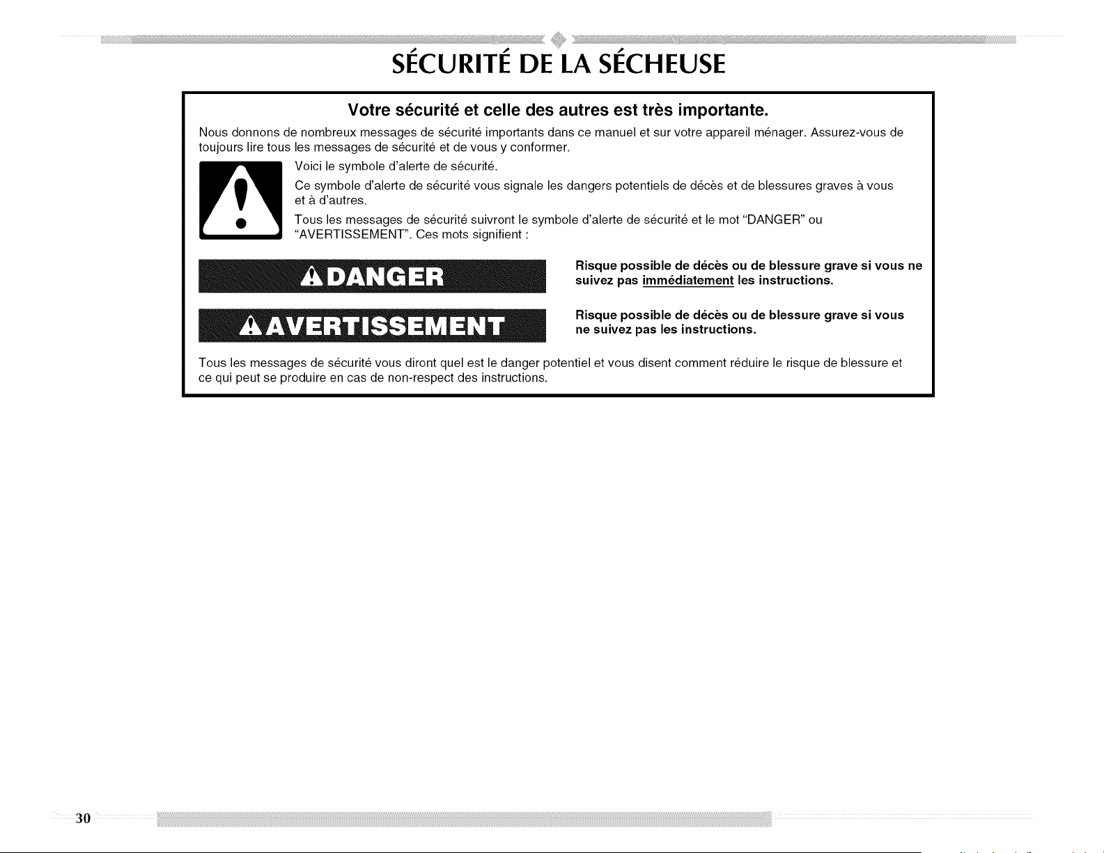
SECURITE DE LA SECHEUSE
Votre securite et celle des autres est tres importante.
Nous donnons de nombreux messages de s_curit_ importants dans ce manuel et sur votre appareil m_nager. Assurez-vous de
toujours lire tous les messages de s_curit_ et de vous y conformer.
Voici le symbole d'alerte de s_curit&
Ce symbole d'alerte de s_curit_ vous signale les dangers potentiels de d_c_s et de blessures graves & vous
et & d'autres.
Tous les messages de s_curit_ suivront le symbole d'alerte de s_curit_ et le mot "DANGER" ou
"AVERTISSEMENT". Ces mots signifient •
Risque possible de d_cbs ou de blessure grave si vous ne
suivez pas imm_diatement les instructions.
Risque possible de d_cbs ou de blessure grave si vous
ne suivez pas les instructions.
Tousles messages de s_curit_ vous diront quel est le danger potentiel et vous disent comment r_duire le risque de blessure et
ce qui peut se produire en cas de non-respect des instructions.
30
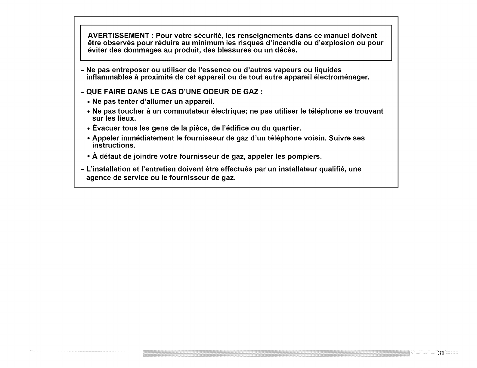
AVERTISSEMENT : Pour votre s_curit_, les renseignements dans ce manuel doivent
_tre observds pour rdduire au minimum les risques d'incendie ou d'explosion ou pour
dviter des dommages au produit, des blessures ou un ddc_s.
- Ne pas entreposer ou utiliser de I'essence ou d'autres vapeurs ou liquides
inflammables _ proximit_ de cet appareil ou de tout autre appareil dlectromdnager.
- QUE FAIRE DANS LE CAS D'UNE ODEUR DE GAZ :
• Ne pas tenter d'allumer un appareil.
• Ne pas toucher _ un commutateur dlectrique; ne pas utiliser le t_ldphone se trouvant
sur les lieux.
• I_vacuer tousles gens de la piece, de I'ddifice ou du quartier.
• Appeler immddiatement le fournisseur de gaz d'un t_ldphone voisin. Suivre ses
instructions.
• A ddfaut de joindre votre fournisseur de gaz, appeler les pompiers.
- L'installation et I'entretien doivent _tre effectuds par un installateur qualifid, une
agence de service ou le fournisseur de gaz.
AVERTISSEMENT : L'odorat ne permet pas toujours la detection d'une fuite de gaz.
Les distributeurs de gaz recommandent I'emploi d'un detecteur de gaz (homologation UL ou CSA).
Pour d'autre information, contacter le fournisseur de gaz local.
En cas de detection d'une fuite de gaz, executer les instructions "Que faire dans le cas d'une odeur de gaz".
JMPORTANTES INSTRUCTIONS DE SECURJT#
AVERTISSEMENT • Pour reduire le risque d'incendie, de choc electrique ou de blessure lots de I'utilisation de
la secheuse, il convient d'observer certaines precautions el6mentaires dont les suivantes :
[] Lire toutes les instructions avant d'utiliser la secheuse.
[] Ne pas placer des articles exposes aux huiles de cuisson
dans votre secheuse. Les articles contamines par des
huiles de cuisson peuvent contribuer & une reaction
chimique qui pourrait causer & la charge de s'enflammer.
[] Ne pas faire secher dans la machine des articles qui ont
deja 6te nettoyes, laves, imbibes, ou taches d'essence,
de solvants pour nettoyage & sec, d'autres substances
inflammables, ou de substances explosives puisqu'elles
degagent des vapeurs qui peuvent provoquer un
incendie ou une explosion.
[] Ne pas permettre & des enfants de jouer sur ou &
I'interieur de la secheuse. Une surveillance etroite est
necessaire Iorsque la secheuse est utilisee pres d'eux.
[] Avant d'enlever la secheuse du service ou la jeter, enlever
la porte du compartiment de sechage.
[] Ne pas mettre la main dans la secheuse si le tambour est
en mouvement.
[] Ne pas installer ni entreposer la secheuse ou elle sera
exposee aux intemperies.
[] Ne pas jouer avec les commandes.
[] Ne pas reparer ni remplacer une piece de la secheuse ou
essayer d'en faire I'entretien & moins d'une recommandation
specifique dans le guide d'utlilisation et d'entretien, ou
publiee dans les instructions de reparation par I'utilisateur
que vous comprenez et pouvez executer avec competence.
[] Ne pas utiliser un produit assouplissant de tissu ou des
produits pour eliminer la statique & moins qu'ils ne soient
recommandes par le fabricant du produit assouplissant de
tissu ou du produit.
[] Ne pas utiliser la chaleur pour faire secher des articles
fabriques avec du caoutchouc mousse ou des materiaux
semblables.
[] Nettoyer le filtre & charpie avant et apres chaque charge.
[] Ne pas laisser la charpie, la poussiere, ou la salete
s'accumuler autour du systeme d'evacuation ou autour de
I'appareil.
[] Un nettoyage periodique de I'interieur de la secheuse et du
conduit d'evacuation dolt _tre effectue par une personne
qualifiee.
[] Voir les instructions d'installation pour les exigences de
liaison de I'appareil & la terre.
CONSERVEZ CES INSTRUCTIONS
IMPORTANT : L'installation du gaz dolt se conformer aux codes Iocaux, ou en I'absence de codes Iocaux, au code canadien
d'installation B149.1 du gaz naturel ou du propane.
La secheuse dolt _tre electriquement reliee & la terre conformement aux codes Iocaux, ou en I'absence de codes Iocaux, au Code
canadien de I'electricit6, CSA C22.1.
32
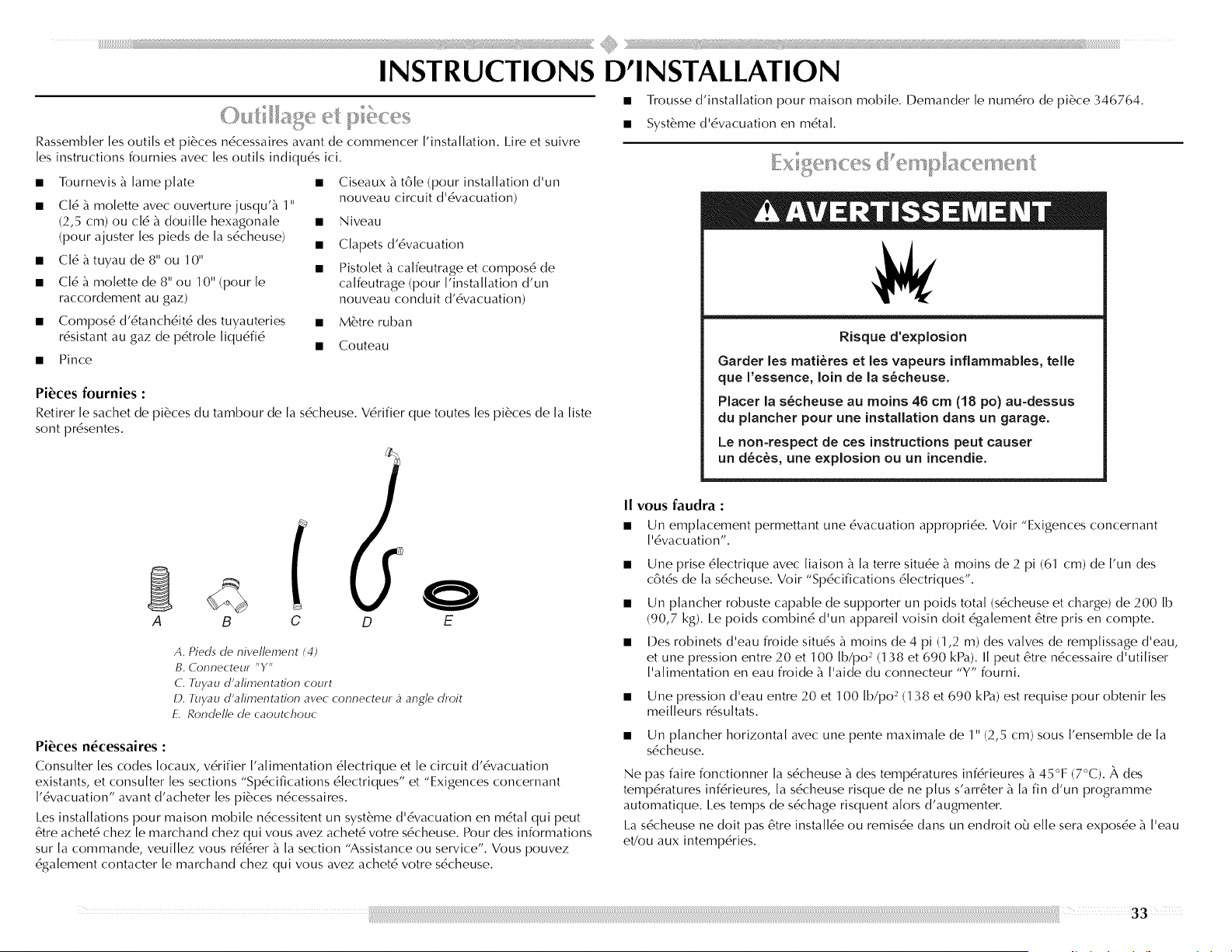
iiiiii_iiil¸ii:iil¸ii_ii¸ii_ii¸ii_ii¸I¸I¸)I_ii_ii)i))ll)il¸ii'ii¸ii'ii¸ii'ii¸ii'ii¸ii'ii¸ii'ii¸ii'ii¸ii'ii¸ii'_iiii)ii)iiii)¸ii¸ii¸))ii¸ii_iii¸iiiiiiiiiii¸ii!iiiiii¸ii!iiiiii¸ii!iiiiiiiiiiiiiiiiiiiiiiiiiiiiiiiiiiiiiiiiiiiiiiilll<iiiiiiiiii)))!'¸ s))l)_l_;_;_i_;i_)))_;_;_;_;_;_;_;_;_;ii_iiili_)I iii_ii_i)iii....... iii_iiiii_IIIIIIIIIIIIIIIIIIIIIIIIIII¸¸i
INSTRUCTIONS D'INSTALLATION
Rassembler [es outils et pi6ces n6cessaires avant de commencer ['installation. I.ire et suiwe
les instructions fournies avec les outils indiqu6s ici.
Tournevis £ lame plate
CI6 £ molette avec ouverture jusqu'£ 1"
(2,5 cm) ou cl6 £ douille hexagonale
(pour ajuster [es pieds de [a s6cheuse)
• CI6 £ tuyau de 8" ou 10"
• C[6 £ mo[ette de 8" ou 10" (pour [e
raccordement au gaz)
Ciseaux £ tB[e (pour installation d'un
nouveau circuit d'6vacuation)
• Niveau
• Clapets d'6vacuation
Pistolet £ calfeutrage et compos6 de
calfeutrage (pour I'installation d'un
nouveau conduit d'6vacuation)
• Compos6 d'6tanch6it6 des tuyauteries • M6tre ruban
r6sistant au gaz de p6tro[e [iqu6fi6
• Couteau
• Pince
Pi6ces fournies :
Retirer le sachet de pi6ces du tambour de la s6cheuse. V6rifier que toutes les pi6ces de la liste
sont pr6sentes.
A B C D E
A. Pieds de nivel/ement (4)
B. Connecteur "Y"
C. 7uyau d'afimentation court
D. 7uyau d'afimentation avec connecteur _ angle droit
E. Ronde//e de caoutchouc
Pi6ces n6cessaires :
Consulter les codes Iocaux, v6rifier I'alimentation 6lectrique et le circuit d'6vacuation
existants, et consulter [es sections "Sp6cifications 6[ectriques" et "Exigences concernant
['6vacuation" avant d'acheter [es pi6ces n6cessaires.
I_esinstallations pour maison mobile n6cessitent un syst6me d'6vacuation en m6ta[ qui peut
@re achet6 chez [e marchand chez qui vous avez achet6 votre s6cheuse. Pour des informations
sur [a commande, veui[[ez vous r6f6rer £ [a section "Assistance ou service". Vous pouvez
6ga[ement contacter [e marchand chez qui vous avez achet6 votre s6cheuse.
• Trousse d'installation pour maison mobile. I)emander le num6ro de pi6ce 346764.
• Syst6me d'6vacuation en m6tal.
Risque d'explosion
Garder les mati_res et les vapeurs inflammables, teiie
que ['essence, loin de [a s_cheuse.
Placer [a s_cheuse au moins 46 cm (18 po) au-dessus
du piancher pour une installation darts un garage.
Le non-respect de ces instructions peut causer
un d_c_s, une explosion ou un incendie.
II vous faudra :
• Un emplacement permettant une 6vacuation appropri6e. Voir "Exigences concernant
['6vacuation".
Une prise 6lectrique avec liaison £ la terre situ6e £ moins de 2 pi (61 cm) de I'un des
cBt6s de la s6cheuse. Voir "Sp6cifications 6lectriques".
Un plancher robuste capable de supporter un poids total (s6cheuse et charge) de 200 Ib
(90,7 kg). I.e poids combin6 d'un appareil voisin dolt 6galement 6tre pris en compte.
I)es robinets d'eau froide situ6s £ moins de 4 pi (1,2 m) des valves de remplissage d'eau,
et une pression entre 20 et 1O0 Ib/po _ (138 et 690 kPa). II peut 6tre n6cessaire d'utiliser
I'alimentation en eau froide £ I'aide du connecteur "Y" fourni.
• Une pression d'eau entre 20 et 1 O0 Ib/po j (138 et 690 kPa) est requise pour obtenir les
meilleurs r6sultats.
• Un plancher horizontal avec une pente maximale de 1" (2,5 cm) sous I'ensemble de la
s6cheuse.
Ne pas faire fonctionner la s6cheuse _ des temp6ratures inf6rieures _ 45°F (7°C). _, des
temp6ratures inf6rieures, [a s6cheuse risque de ne plus s'arr6ter _ [a fin d'un programme
automatique. I.es temps de s6chage risquent a[ors d'augmenter.
La s6cheuse ne doit pas @re insta[[6e ou remis6e dans un endroit o5 e[[e sera expos6e _ ['eau
et/ou aux intemp6ries.
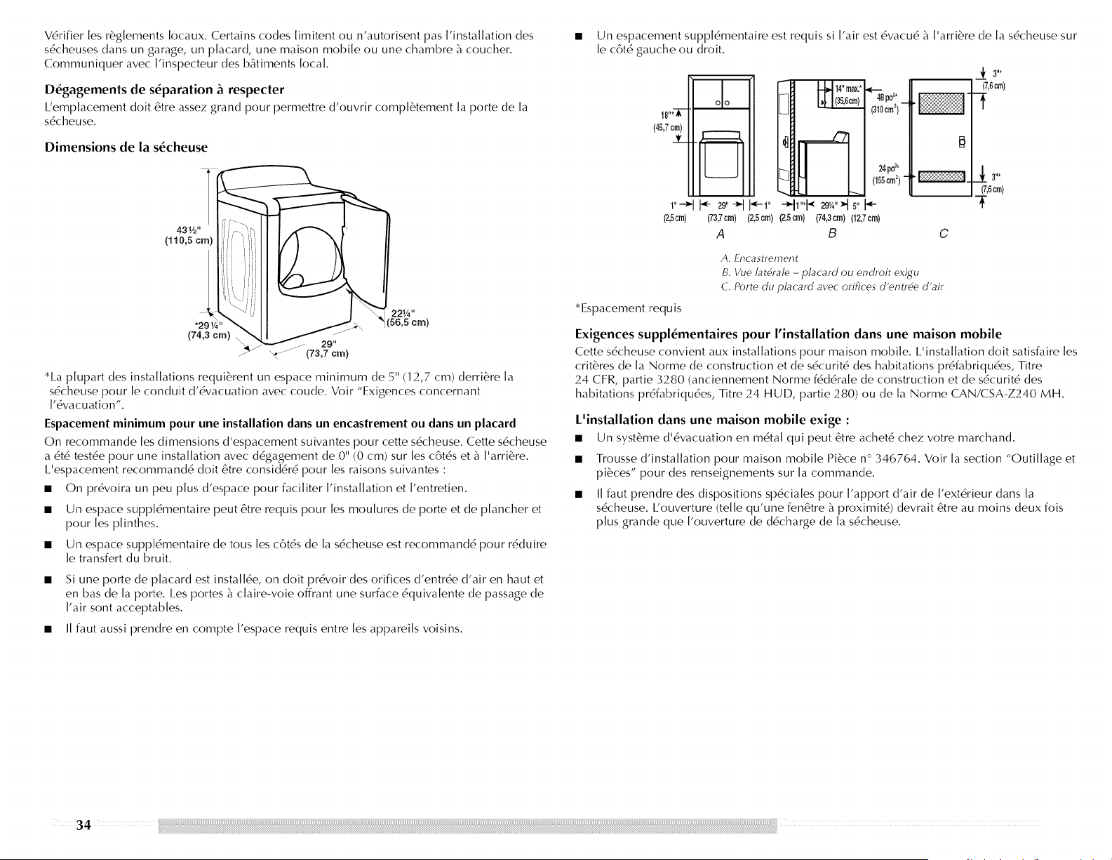
V6rifierlesr6glementsIocaux.Certainscodeslimitentoun'autorisentpasI'installationdes
s6cheusesdansungarage,unplacard,unemaisonmobileouunechambre_coucher.
CommuniqueravecI'inspecteurdesb&timentslocal.
D_gagements de s_paration _ respecter
I.'emplacement doit 6tre assez grand pour permettre d'ouvrir compl6tement la porte de la
s6cheuse.
Dimensions de la s_cheuse
*l_a plupart des installations requi6rent un espace minimum de 5" (12,7 cm) derri6re la
s6cheuse pour le conduit d'6vacuation avec coude. Voir "Exigences concernant
1'6vacuation'.
Espacement minimum pour une installation dans un encastrement ou dans un placard
On recommande les dimensions d'espacement suivantes pour cette s6cheuse. Cette s6cheuse
a 6t6 testde pour une installation avec d6gagement de 0" (0 cm) sur [es c6tds et _ ['arri_re. •
I.'espacement recommand6 doit 6tre consid6r6 pour [es raisons suivantes :
• On pr6voira un peu plus d'espace pour faci[iter ['installation et ['entretien.
• Un espace suppl6mentaire peut 6tre requis pour les moulures de porte et de plancher et
pour les plinthes.
• Un espace suppl6mentaire de tousles c6t6s de la s6cheuse est recommand6 pour r6duire
le transfert du bruit.
Si une porte de placard est install6e, on doit pr6voir des orifices d'entr6e d'air en haut et
en bas de la porte. I.es portes _ claire-voie offrant une surface 6quivalente de passage de
I'air sont acceptables.
• II faut aussi prendre en compte I'espace requis entre les appareils voisins.
Un espacement suppl6mentaire est requis si I'air est 6vacu6 _ I'arri6re de la s6cheuse sur
le c6t6 gauche ou droit.
[_] I_ 1(3b,_cm.,._,__}
___ ----
1"*__w'-t 5,,
(2,5cm)
*Espacement requis
• 48po2,
(310cm2)
24_*
(155cm2)"
(-
(73,7cm)(2,Scrn)(2,5crn) (74,3crn)(12,7crn)
A B C
_f 3"*
(7,6cm)
(7,6cm)
i-
A. Lncastrel_ent
t3. Vue lat6rale -placard ou endroit exigu
C. Porte du _lac-ard avec- orifices d'entr6e d'air
Exigences suppl_mentaires pour I'installation dans une maison mobile
Cette s6cheuse convient aux installations pour maison mobile. I_'installation doit satisfaire [es
crit_'res de la Norme de construction et de s6curit6 des habitations pr6fabriqu6es, Titre
24 CFR, partie 3280 (anciennement Norme f6d6rale de construction et de s6curit6 des
habitations pr6fabriqu6es, Titre 24 HUE), partie 280) ou de la Norme CAN/CSA-Z240 MH.
L'installation dans une maison mobile exige :
• Un syst_me d'6vacuation en m6tal qui peut 6tre achet6 chez votre marchand.
Trousse d'installation pour maison mobile Pi6ce n ° 346764. Voir la section "Outillage et
pi6ces" pour des renseignements sur la commande.
II faut prendre des dispositions sp6ciales pour I'apport d'air de I'ext6rieur dans la
s6cheuse. I:ouverture (telle qu'une fen6tre _ proximit6) devrait 6tre au moins deux fois
plus grande que I'ouverture de d6charge de la s6cheuse.
_ _£,, ...... ,.,,, ,. s...... s. s......
Risque de choc 61ectrique
Brancher sur une prise & 3 alv6oles reli6e & la terre.
Ne pas enlever la broche de liaison & la terre.
Ne pas utiliser un adaptateur.
Ne pas utJHser un c&ble de rallonge.
Le non-respect de ces instructions peut causer
un d6c_s, un incendie ou un choc 61ectrique.
I/appareil doit 6tre aliment6 par un circuit de 120 V, CA seulement, 60 Hz, 1,5 ou
20 amp6res, protdg6 par un fusible. On recommande I'emploi d'un fusible ou d'un
disjoncteur temporis6. II est recommand6 de raccorder I'appareil sur un circuit distinct
exclusif b_cet appareil.
iNSTRUCTiONS DE LiAiSON A LA TERRE
[] Pour une s6cheuse reli6e & la terre et connect6e par
un cordon :
Cette s6cheuse doit 6tre reli6e & la terre. En cas de mauvais
fonctionnement ou de panne, la liaison & la terre r6duira le
risque de choc 61ectrique en offrant au courant 61ectrique un
acheminement d'6vacuation de moindre r6sistance. Cette
s6cheuse est aliment6e par un cordon 61ectrique comportant
un conducteur reli6 & la terre et une fiche de branchement
munie d'une broche de liaison & la terre. La fiche doit 6tre
branch6e sur une prise appropri6e qui est bien install6e et
reli6e a la terre conform6ment a tous les codes et r6glements
Iocaux.
AVERTISSEIVlENT " Le raccordement incorrect de
cet appareil au conducteur de liaison & la terre peut susciter
un risque de choc 61ectrique. En cas de doute quant & la
qualit6 de liaison & la terre de la s6cheuse, consulter un
61ectricien ou un technicien ou un personnel qualifi6. Ne pas
modifier la fiche de branchement fournie avec la s6cheuse;
si la fiche ne correspond pas & la configuration de la prise de
courant, demander & un 61ectricien qualifi6 d'installer une
prise de courant appropri6e.
CONSERVEZ CES INSTRUCTIONS
Risque d'explosion
Utiliser une canalisation neuve d'arriv6e de gaz
approuv6e par CSA International.
Installer un robinet d'arr6t.
Bien serrer chaque organe de connexion de la
canalisatJon de gaz.
En cas de connexion au gaz propane, demander & une
personne qualifi6e de s'assurer que la pressJon de gaz
ne d6passe pas 33 cm (13 po) de la colonne d'eau.
Par personne qualifi6e, on comprend :
le personnel autorJs6 de chauffage,
le personnel autoris6 d'une compagnie de gaz, et
le personnel d'entretien autoris6.
Le non-respect de ces instructions peut causer
un d6c_s, un explosion ou un incendie.
Type de gaz
Gaz naturel :
Cette sdcheuse est 6quipde pour une alimentation au gaz naturel. Sa conception est
homologude par la CSA International pour I'alimentation au gaz de pdtrole liqudfi6 (propane
ou butane), avec conversion appropri6e.
• Cette sdcheuse doit 6tre 6quipde du brOleur convenable, correspondant au gaz spdcifique
qui alimente I'habitation. I/information sur le brOleur se trouve sur la plaque signal@ique
dans le Iogement de la porte de la sdcheuse. Si cette information ne correspond pas au
type de gaz disponible, contacter votre marchand ou composer les numdros de tdldphone
indiquds sur la page de couverture de ce manuel.
Conversion au gaz de p6trole liqu6fi6 :
Un technicien qualifi6 dolt effectuer la conversion.
Ne pas entreprendre de convertir I'appareil pour I'utilisation d'un gaz diff6rent de celui
indiqu6 sur la plaque signal@ique sans d'abord consulter le fournisseur de gaz. Pour des
renseignements sur la commande d'un ensemble de conversion au gaz propane, se rdfdrer b_
la section "Assistance ou service". Demander la pi6ce n ° 49572.
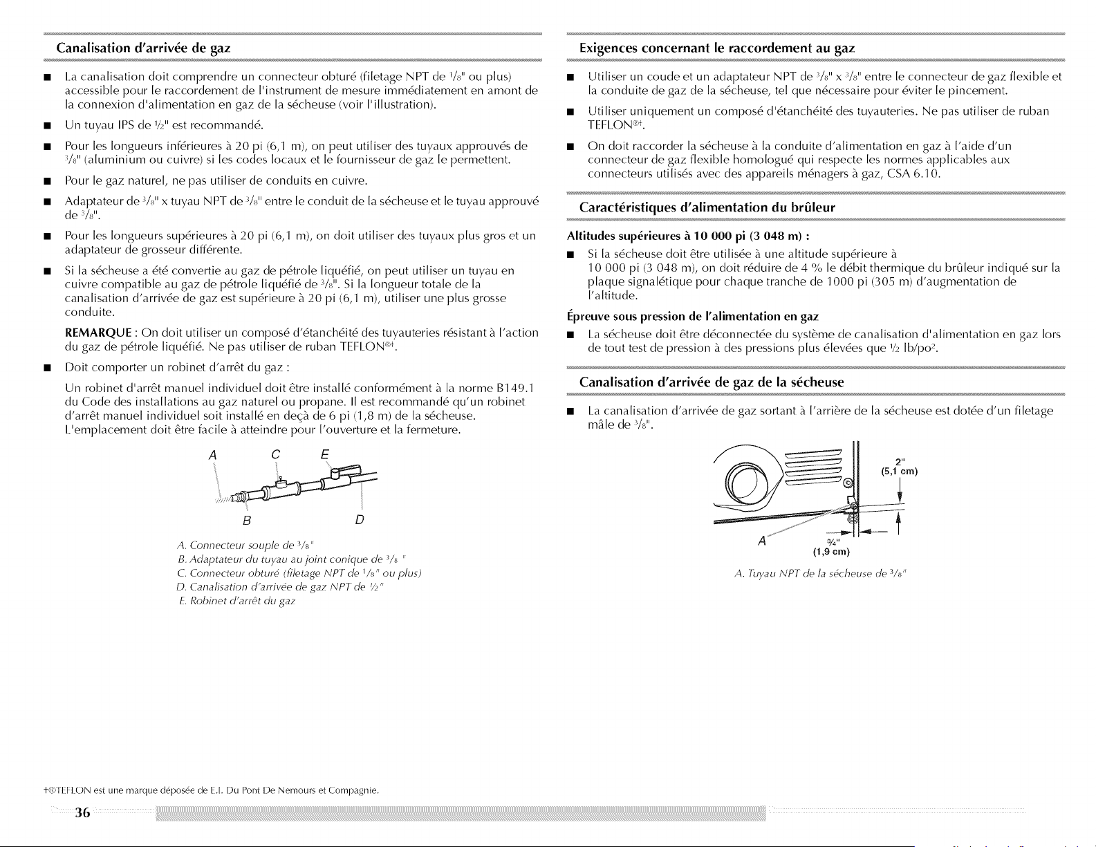
Canalisation d'arriv_e de gaz
I.a canalisation doit comprendre un connecteur obtur6 (filetage NPT de I/_ u OU plus)
accessible pour le raccordement de I'instrument de mesure imm6diatement en amont de
la connexion d'alimentation en gaz de la s6cheuse (voir I'illustration).
Un tuyau IPS de 1/2" est recommand6.
Pour les Iongueurs inf6rieures _ 20 pi (6,1 m), on peut utiliser des tuyaux approuv6s de
3/8" (aluminium ou cuivre) si les codes Iocaux et le fournisseur de gaz le permettent.
Pour le gaz naturel, ne pas utiliser de conduits en cuivre.
Adaptateur de 3/_,, x tuyau NPT de 3/_,,entre le conduit de la s6cheuse et le tuyau approuv6
de %".
Pour les Iongueurs sup6rieures _ 20 pi (6,1 m), on doit utiliser des tuyaux plus gros et un
adaptateur de grosseur diff6rente.
Si la s6cheuse a 6t6 convertie au gaz de pdtrole liqu6fi6, on peut utiliser un tuyau en
cuivre compatible au gaz de p6tro[e [iqu6fi6 de %". Si [a [ongueur tota[e de [a
cana[isation d'arriv6e de gaz est sup6rieure b_20 pi (6,1 m), uti[iser une plus grosse
conduite.
REMARQUE : On doit utiliser un compos6 d'6tanch6it6 des tuyauteries r6sistant b_['action
du gaz de p6tro[e [iqu6fi6. Ne pas uti[iser de ruban TEFI.ON k_*.
• Doit comporter un robinet d'arr6t du gaz :
Un robinet d'arr6t manuel individuel doit 6tre install6 conform6ment _ la norme B149.1
du Code des installations au gaz naturel ou propane. II est recommand6 qu'un robinet
d'arr6t manuel individuel soit install6 en deq_ de 6 pi (1,8 m) de la s6cheuse.
I.'emplacement doit 6tre facile _ atteindre pour I'ouverture et la fermeture.
A C E
B D
A. Connecteur soup/e de 3/_,,
B. Adaptateur du tuyau au joint conique de 3/_ ,,
C. Connecteur obturd (filetage NPT de 1/_,, ou plus)
D. Canafisation d'arrivde eye gaz NPT eye 7/_,,
E. Robinet d'arr6t du gaz
Exigences concemant le raccordement au gaz
Utiliser un coude et un adaptateur NPT de %" x %" entre le connecteur de gaz flexible et
la conduite de gaz de la s6cheuse tel que n6cessaire pour 6viter le pincement.
Utiliser uniquement un compos6 d'6tanch6it6 des tuyauteries. Ne pas utiliser de ruban
T EFI.ON:'L
On doit raccorder la s6cheuse _ la conduite d'alimentation en gaz _ I'aide d'un
connecteur de gaz flexible homologu6 qui respecte les normes applicables aux
connecteurs utilis6s avec des appareils m6nagers _ gaz, CSA 6.10.
Caract_ristiques d'alimentation du br_leur
Altitudes sup_rieures _ 10 000 pi (3 048 m) :
• Si la s6cheuse doit 6tre utilisde b_une altitude supdrieure b_
10 000 pi (3 048 m), on doit r6duire de 4 % [e d6bit thermique du brO[eur indiqu6 sur [a
plaque signa[6tique pour chaque tranche de 1000 pi (305 m) d'augmentation de
['altitude.
I_preuve sous pression de I'alimentation en gaz
• I.a s6cheuse doit 6tre d6connect6e du syst6me de canalisation d'alimentation en gaz Iors
de tout test de pression b_des pressions plus 6[ev6es que 1/2[b/po 2.
Canalisation d'arriv_e de gaz de la s_cheuse
I.a canalisation d'arriv6e de gaz sortant _ I'arri6re de la s6cheuse est dot6e d'un filetage
m&le de %".
(1,9 era)
A. 7uyau NPT de/a sdcheuse de 3/_,,
t-(t<)TEF[ ON est une marque d6pos&e de E.[. Du Pont IDe Nemours et Compagme.
36
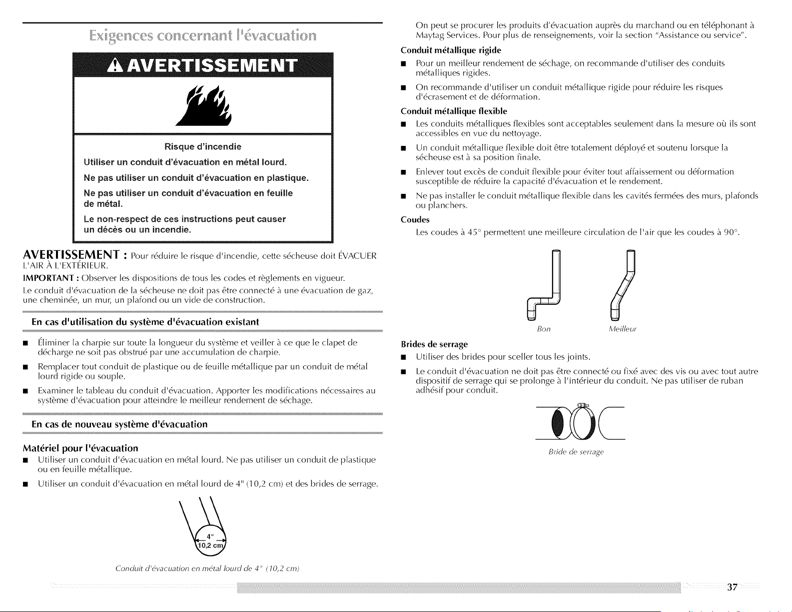
Risque d'incendie
Utiiiser un conduit d'_vacuation en m_tal Iourd.
Ne pas utiliser un conduit d'_vacuation en plastique.
Ne pas utiliser un conduit d'_vacuation en feuille
de m_tal.
Le non-respect de ces instructions peut causer
un d_c_s ou un incendie.
On peut se procurer les produits d'6vacuation aupr6s du marchand ou en t616phonant
Maytag Services. Pour plus de renseignements, voir [a section "Assistance ou service".
Conduit m_tallique rigide
• Pour un mei[[eur rendement de s6chage, on recommande d'uti[iser des conduits
m6ta[[iques rigides.
• On recommande d'uti[iser un conduit m6ta[[ique rigide pour r6duire [es risques
d'6crasement et de d6formation.
Conduit m_tallique flexible
• I.es conduits m6ta[[iques f[exib[es sont acceptab[es seu[ement dans [a mesure o_ i[s sont
accessib[es en vue du nettoyage.
• Un conduit m6ta[[ique flexible doit 6tre tota[ement d6p[oy6 et soutenu [orsque [a
s6cheuse est _ sa position finale.
• En[ever tout exc_s de conduit flexible pour 6viter tout affaissement ou d6formation
susceptible de r6duire [a capacit6 d'6vacuation et [e rendement.
• Ne pas installer [e conduit m6ta[[ique flexible dans [es cavit6s ferm6es des murs, p[afonds
ou p[anchers.
Coudes
I.es coudes _ 45 ° permettent une mei[[eure circulation de ['air que [es coudes _ 90 °.
AVERTISSEMENT : Pour r6duire [e risque d'incendie, cette s6cheuse doit EVACUER
I.'AIR _, I.'EXTERIEUR.
IMPORTANT : Observer [es dispositions de tous[es codes et r_g[ements en vigueur.
I.e conduit d'6vacuation de [a s6cheuse ne doit pas 6tre connect6 _ une 6vacuation de gaz,
une chemin6e, un mub un p[afond ou un vide de construction.
En cas d'utilisation du syst_me d'_vacuation existant
• E[iminer [a charpie sur toute [a [ongueur du syst_me et vei[[er _ ce que [e c[apet de
d6charge ne soit pas obstru6 par une accumulation de charpie.
• Remp[acer tout conduit de p[astique ou de feui[[e m6ta[[ique par un conduit de m6ta[
[ourd rigide ou soup[e.
• Examiner [e tableau du conduit d'6vacuation. Apporter [es modifications n6cessaires au
syst_me d'6vacuation pour atteindre [e mei[[eur rendement de s6chage.
En cas de nouveau syst_me d'_vacuation
Materiel pour I'_vacuation
• Uti[iser un conduit d'6vacuation en m6ta[ [ourd. Ne pas uti[iser un conduit de p[astique
ou en feui[[e m6ta[[ique.
• Uti[iser un conduit d'6vacuation en m6ta[ [ourd de 4" (1 0,2 cm) et des brides de serrage.
Conduit d'dvacuation en mdtal Iourd de 4" ( 10,2 cm)
Brides de serrage
Bon Meilleur
Utiliser des brides pour sceller tousles joints.
I.e conduit d'6vacuation ne doit pas 6tre connect6 ou fix6 avec des vis ou avec tout autre
dispositif de serrage qui se prolonge _ I'int6rieur du conduit. Ne pas utiliser de ruban
adh6sif pour conduit.
Bride de serrage
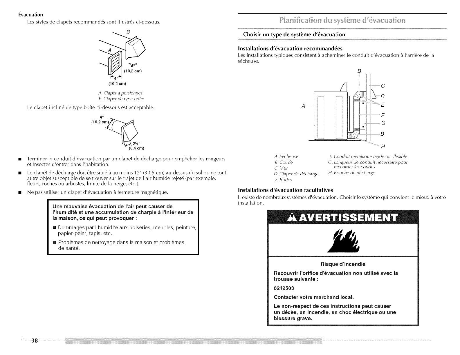
I_vacuation
I.es styles de clapets recommand6s sont illustr6s ci-dessous.
(10,2 em)
A. Clapet _ persiennes
B. Clapet de type boite
I.e c[apet inc[in6 de type bo?te ci-dessous est acceptable.
4"
(10,2 cm_(_
_.._ 21/2"
,4 cm)
• Terminer [e conduit d'6vacuation par un clapet de d6charge pour emp&her [es rongeurs
et insectes d'entrer dans ['habitation.
• I.e c[apet de d6charge dolt 6tre situ6 b_au moins 12" (30,5 cm) au-dessus du so[ ou de tout
autre objet susceptible de se trouver sur [e trajet de ['air humide rejet6 (par exemp[e,
f[eurs, roches ou arbustes, [imite de [a neige, etc.).
• Ne pas uti[iser un c[apet d'6vacuation b_fermeture magn6tique.
Une mauvaise _vacuation de N'air peut causer de
I'humidit_ et une accumulation de charpie _ rint_rieur de
la maison, ce qui peut provoquer :
[] Dommages par I'humidite aux boiseries, meubles, peinture,
papier-peint, tapis, etc.
[] Problemes de nettoyage dans la maison et problemes
de sante.
(_u sv> <!_ _ :t <:
Choisir un type de syst_me d'_vacuation
Installations d'_vacuation recommand_es
I.es installations typiques consistent b_acheminer le conduit d'6vacuation b_I'arri_re de la
s6cheuse.
A
/1
B
I .................. C
q B
H
A. 56cheuse
B. Coude
C. Mur
D. C/apet de d6chaJge
E. Brides
£ Conduit m6tallique rigide ou flexible
C. Ion.gueur..... de conduit n6cessaire pour
raccorder les coudes
H. Bouche de d6charge
Installations d'_vacuation facultatives
II existe de nombreux syst&mes d'6vacuation. Choisir le syst&me qui convient le mieux _ votre
installation.
Risque d'incendie
Recouvrir I'orifice d'_vacuation non utiiis_ avec la
trousse suivante :
8212503
Contacter votre marchand local.
Le non-respect de ces instructions peut causer
un d_c_s, un incendie, un choc _[ectrique ou une
biessure grave.
38
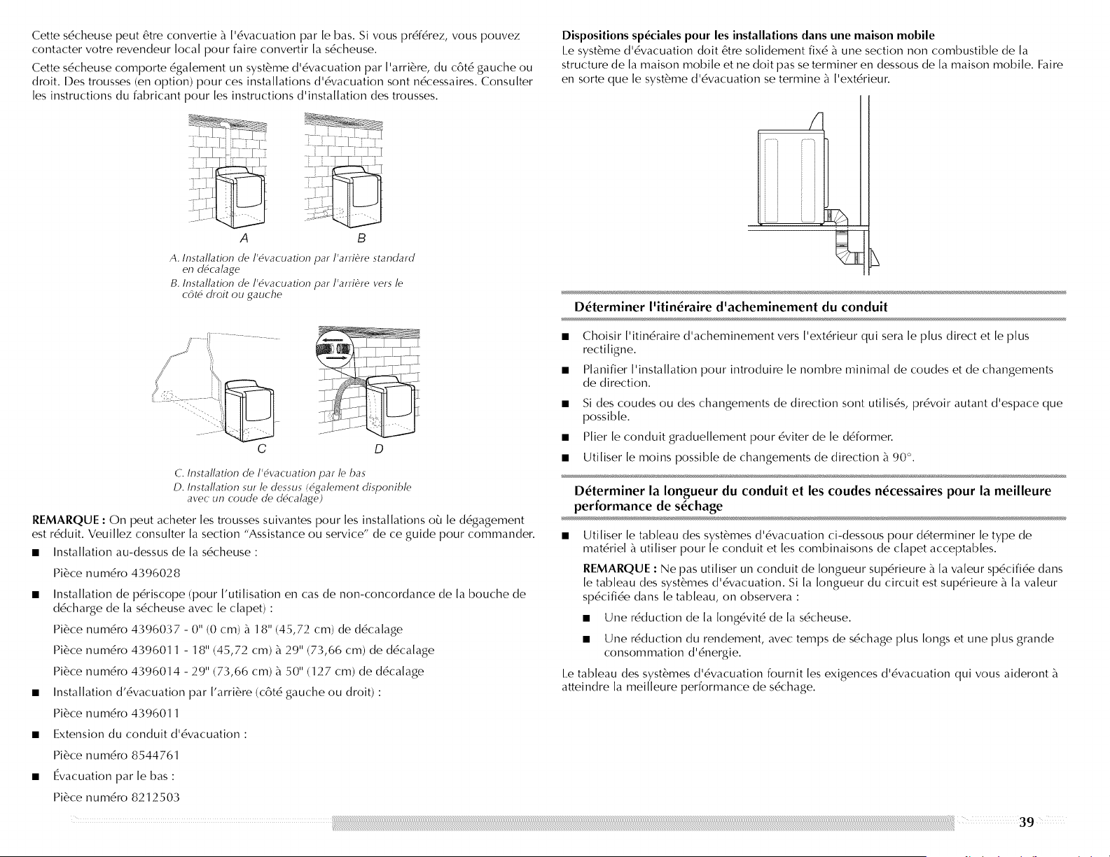
Cette sdcheuse peut 6tre convertie _ l'6vacuation par le bas. Si vous pr6f6rez, vous pouvez
contacter votre revendeur local pour faire convertir la s6cheuse.
Cette s6cheuse comporte 6galement un syst_'me d'6vacuation par I'arri6re, du c6t6 gauche ou
droit. Des trousses (en option) pour ces installations d'6vacuation sont n6cessaires. Consulter
les instructions du fabricant pour les instructions d'installation des trousses.
A B
A. Installation de/'6vacuation par/'arri_re standard
en d6cabge
B. Installation de 1'6vacuation par I'arri_re vers /e
c6t6 droit ou gauche
Dispositions sp_ciales pour les installations dans une maison mobile
I.e syst&me d'6vacuation doit &tre solidement fix6 _ une section non combustible de la
structure de [a maison mobile et ne doit passe terminer en dessous de [a maison mobile. Faire
en sorte que [e syst_'me d'6vacuation se termine _ ['ext6rieur.
/
D_terminer I'itin_raire d'acheminement du conduit
C D
C. Instaflation de 1'6vacuation par/e bas
D. Insta//ation sur /e dessus (6ga/ement disponib/e
avec un coude de d6ca/age)
REMARQUE : On peut acheter [es trousses suivantes pour [es installations o_J[e d6gagement
est r6duit. Veui[[ez consulter [a section "Assistance ou service" de ce guide pour commander.
• Installation au-dessus de [a s6cheuse :
Pi6ce num6ro 4396028
• Installation de p6riscope (pour ['uti[isation en cas de non-concordance de [a bouche de
d6charge de [a s6cheuse avec [e c[apet) :
Pi6ce num6ro 4396037 - 0" (0 cm) _ 18" (45,72 cm) de d6ca[age
Pi6ce num6ro 4396011 - 18" (45,72 cm) _ 29" (73,66 cm) de d6ca[age
Pi6ce num6ro 4396014 - 29" (73,66 cm) _ 50" (127 cm) de d6ca[age
• Installation d'6vacuation par ['arri6re (c6t6 gauche ou droit) :
Pi6ce num6ro 4396011
• Extension du conduit d'6vacuation :
Pi6ce num6ro 8544761
• Evacuation par [e bas :
Pi6ce num6ro 8212503
-[- ......1_ •
- :j
.
Choisir ['itin6raire d'acheminement vers ['ext6rieur qui sera [e plus direct et [e plus
recti[igne.
P[anifier ['installation pour introduire [e hombre minimal de coudes et de changements
de direction.
Si des coudes ou des changements de direction sont utilis6s, pr6voir autant d'espace que
possible.
Plier le conduit graduellement pour 6viter de le d6former.
Utiliser le moins possible de changements de direction _ 90 °.
D_terminer la Iongueur du conduit et les coudes n_cessaires pour la meilleure
performance de s_chage
• Utiliser le tableau des syst6mes d'6vacuation ci-dessous pour d6terminer le type de
mat6riel _ utiliser pour le conduit et les combinaisons de clapet acceptables.
REMARQUE : Ne pas utiliser un conduit de Iongueur sup6rieure _ la valeur sp6cifi6e dans
[e tableau des syst6mes d'6vacuation. Si [a [ongueur du circuit est sup6rieure _ [a va[eur
sp6cifi6e dans [e tableau, on observera :
• Une r6duction de la Iong6vit6 de la s6cheuse.
• Une r6duction du rendement, avec temps de s6chage plus longs et une plus grande
consommation d'6nergie.
I.e tableau des syst6mes d'6vacuation fournit les exigences d'6vacuation qui vous aideront
atteindre la meilleure performance de s6chage.
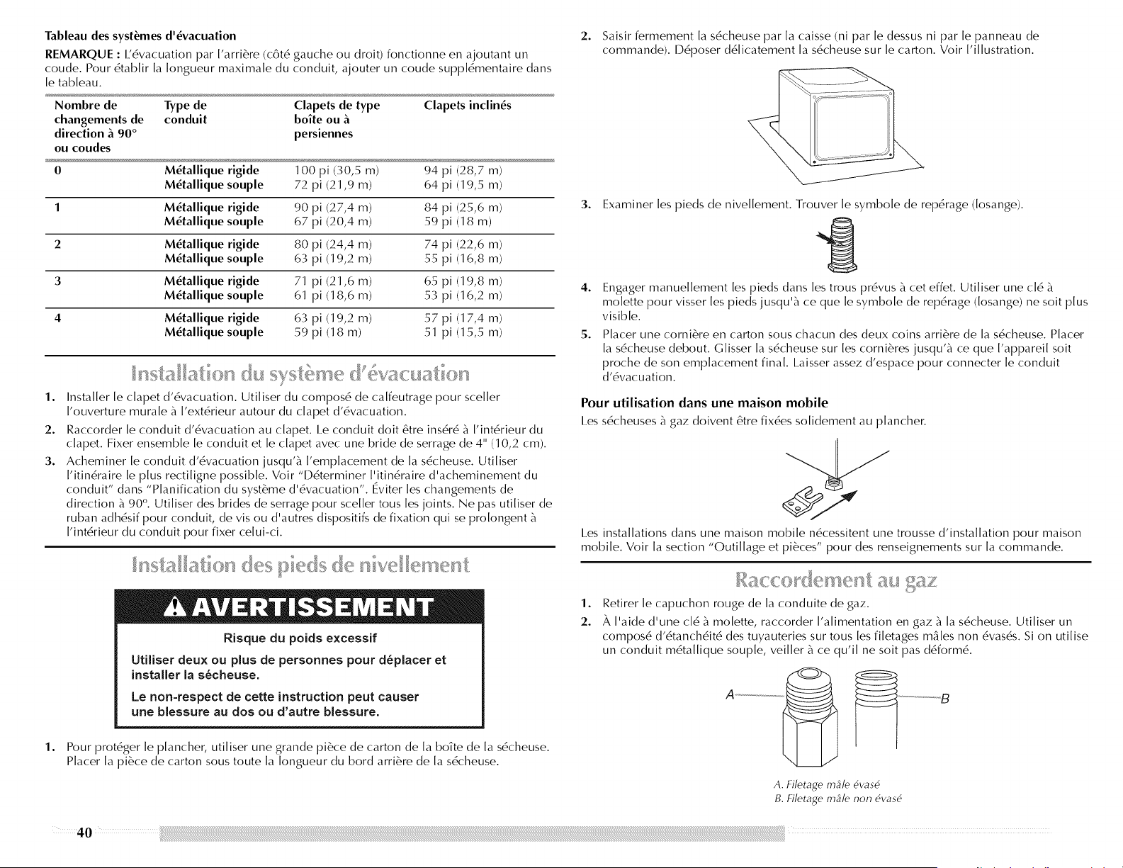
Tableaudes syst_mes d'_vacuation
REMARQUE : 1,6vacuation par I'arri6re (c6t6 gauche ou droit) fonctionne en ajoutant un
coude. Pour 6tab[it [a [ongueur maxima[e du conduit, ajouter un coude supp[6mentaire dans
[e tableau.
Nombre de Type de Clapets de type Clapets inclines
changements de conduit boite ou
direction _ 90 ° persiennes
ou coudes
0 M_tallique rigide 100 pi 130,5 m) 94 pi 128,7 m)
M_tallique souple 72 pi (21,9 m) 64 pi (19,5 m)
1 M_tallique rigide 90 pi (27,4 m) 84 pi (25,6 m)
M_tallique souple 67 pi (20,4 m) 59 pi (18 m)
2 M_tallique rigide 80 pi (24,4 m) 74 pi (22,6 m)
M_tallique souple 63 pi (19,2 m) 55 pi (16,8 m)
3 M_tallique rigide 71 pi (21,6 m) 65 pi (19,8 m)
M_tallique souple 61 pi (18,6 m) 53 pi (16,2 m)
4 M_tallique rigide 63 pi (19,2 m) 57 pi (17,4 m)
M_tallique souple 59 pi (18 m) 51 pi (15,5 m)
1.
2.
3.
Installer le clapet d'6vacuation. Utiliser du compos6 de calfeutrage pour sceller
['ouverture mura[e _ ['ext6rieur autour du c[apet d'6vacuation.
Raccorder [e conduit d'6vacuation au c[apet. I.e conduit doit 6tre ins6r6 _ ['int6rieur du
c[apet. Fixer ensemble [e conduit et [e c[apet avec une bride de serrage de 4" (10,2 cm).
Acheminer [e conduit d'6vacuation jusqu'_ ['emplacement de [a s6cheuse. Uti[iser
['itin6raire [e plus recti[igne possible. Voir "l)6terminer ['itin6raire d'acheminement du
conduit" dans "P[anification du syst6me d'6vacuation". Eviter [es changements de
direction _ 90 °. Uti[iser des brides de serrage pour sce[[er tous[es joints. Ne pas uti[iser de
ruban adh6sif pour conduit, de vis ou d'autres dispositifs de fixation qui se pro[ongent
['int6rieur du conduit pour fixer ce[ui-ci.
Risque du poids excessif
UtiHser deux ou plus de personnes pour d_piacer et
installer la s_cheuse.
Le non=respect de cette instruction peut causer
une blessure au dos ou d'autre blessure.
1. Pour prot6ger le plancher, utiliser une grande pi6ce de carton de la boTte de la s6cheuse.
Placer [a pi6ce de carton sous toute [a [ongueur du bord arri6re de [a s6cheuse.
2. Saisir fermement la s6cheuse par la caisse (ni par le dessus ni par le panneau de
commande). D6poser d6[icatement [a s6cheuse sur [e carton. Voir ['illustration.
3.
4.
5.
Examiner les pieds de nivellement. Trouver le symbole de repdrage (Iosange).
Engager manuellement les pieds dans les trous pr6vus _ cet effet. Utiliser une cl6
mo[ette pour visser [es pieds jusqu'_ ce que [e symbo[e de rep6rage ([osange) ne soit plus
visible.
Placer une corni6re en carton sous chacun des deux coins arri6re de la sdcheuse. Placer
la s6cheuse debout. Glisser la s6cheuse sur les corni6res jusqu'_ ce que I'appareil soit
proche de son emplacement final. I.aisser assez d'espace pour connecter le conduit
d'dvacuation.
Pour utilisation dans une maison mobile
I.es s6cheuses _ gaz doivent 6tre fix6es solidernent au plancher.
I.es installations dans une maison mobile n6cessitent une trousse d'installation pour maison
mobile. Voir la section "Outillage et pi6ces" pour des renseignements sur la commande.
1.
2.
Retirer le capuchon rouge de la conduite de gaz.
_, ['aide d'une c[6 _ mo[ette, raccorder ['a[imentation en gaz _ [a s6cheuse. Uti[iser un
compos6 d'6tanch6it6 des tuyauteries sur tous[es fi[etages m_[es non 6vas6s. Si on uti[ise
un conduit m6ta[[ique soup[e, vei[[er _ ce qu'i[ ne soit pas d6form6.
..................... g
A. Filetage ingle 6vas6
B. _71etage ingle non 6vas6
40
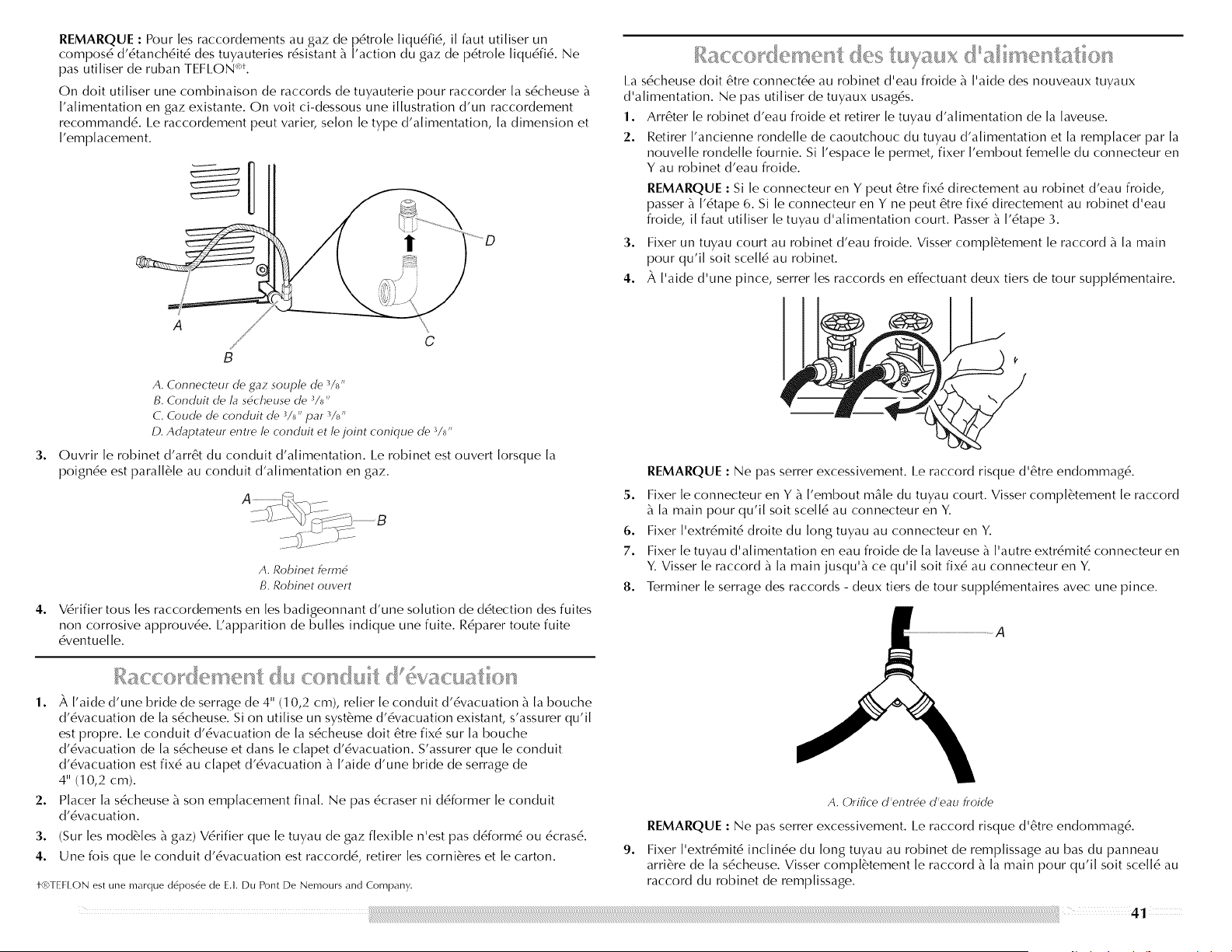
REMARQUE: Pour les raccordements au gaz de p6tro[e liqu6fi6, il faut utiliser un
compos6 d'6tanch6it6 des tuyauteries r6sistant b_['action du gaz de p6tro[e [iqu6fi6. Ne
pas uti[iser de ruban TEFI.ON <_*.
On doit uti[iser une combinaison de raccords de tuyauterie pour raccorder [a s6cheuse b_
['a[imentation en gaz existante. On voit ci-dessous une illustration d'un raccordement
recommand6. Le raccordement peut varier, se[on [e type d'a[imentation, [a dimension et
['emplacement.
!
I.a s6cheuse doit 6tre connect6e au robinet d'eau froide b_['aide des nouveaux tuyaux
d'a[imentation. Ne pas uti[iser de tuyaux usag6s.
1. Arr6ter [e robinet d'eau froide et retirer [e tuyau d'a[imentation de [a [aveuse.
2. Retirer ['ancienne ronde[[e de caoutchouc du tuyau d'a[imentation et [a remp[acer par [a
nouve[[e ronde[[e foumie. Si ['espace [e permet, fixer ['embout feme[[e du connecteur en
Y au robinet d'eau froide.
REMARQUE : Si le connecteur en Y peut 6tre fix6 directement au robinet d'eau froide,
passer _ 1'6tape 6. Si le connecteur en Y ne peut 6tre fix6 directement au robinet d'eau
froide, il faut utiliser le tuyau d'alimentation court. Passer _ 1'6tape 3.
3. Fixer un tuyau court au robinet d'eau froide. Visser compl6tement le raccord _ la main
pour qu'il soit scell6 au robinet.
4. _, I'aide d'une pince, serrer les raccords en effectuant deux tiers de tour suppl6mentaire.
3.
A
B
C
A. Connecteur de gaz souple de 3/_,,
B. Conduit de la sdcheuse de _/_"
C. Coude de conduit de _/_" par _/_"
D. Adaptateur entre le conduit et le joint conique de °_/_"
Ouvrir [e robinet d'arr6t du conduit d'a[imentation. I.e robinet est ouvert [orsque [a
poignde est para[[6[e au conduit d'a[imentation en gaz.
4°
A. Robinet fermd
B. Robinet ouvert
V6rifier tousles raccordements en les badigeonnant d'une solution de d6tection des fuites
non corrosive approuv6e. I.'apparition de bulles indique une fuite. R6parer toute fuite
6ventuelle.
1°
2°
3.
4.
_, I'aide d'une bride de serrage de 4" (1 0,2 cm), relier le conduit d'6vacuation _ la bouche
d'6vacuation de la s6cheuse. Si on utilise un syst_'me d'6vacuation existant, s'assurer qu'il
est propre. I_econduit d'6vacuation de la s6cheuse doit 6tre fix6 sur la bouche
d'6vacuation de la s6cheuse et dans le clapet d'6vacuation. S'assurer que le conduit
d'6vacuation est fix6 au clapet d'6vacuation _ I'aide d'une bride de serrage de
4" (1 0,2 cm).
Placer la s6cheuse _ son emplacement final. Ne pas 6craser ni d6former le conduit
d'6vacuation.
(Sur les mod61es b_gaz) V6rifier que le tuyau de gaz flexible n'est pas d6form6 ou 6cras6.
Une fois que [e conduit d'6vacuation est raccord6, retirer [es corni6res et [e carton.
t-(t0]EF[ ON est une marque d&pos6e de E.I. Du Pont De Nemours and Company.
REMARQUE : Ne pas serrer excessivement. I.e raccord risque d'6tre endommag6.
5. Fixer [e connecteur en Y b_['embout m&[e du tuyau court. Visser comp[6tement [e raccord
b_[a main pour qu'i[ soit sce[[6 au connecteur en Y.
6. Fixer ['extr6mit6 droite du long tuyau au connecteur en Y.
7. Fixer [e tuyau d'a[imentation en eau froide de [a [aveuse b_['autre extr6mit6 connecteur en
Y. Visser [e raccord b_[a main jusqu'b_ ce qu'i[ soit fix6 au connecteur en Y.
8. Terminer [e serrage des raccords - deux tiers de tour supp[6mentaires avec une pince.
9°
A
A. Orifice d'entrde d'eau froide
REMARQUE : Ne pas serrer excessivement. I.e raccord risque d'6tre endommag6.
Fixer I'extr6mit6 inclin6e du long tuyau au robinet de remplissage au bas du panneau
arri6re de la s6cheuse. Visser compl6tement le raccord _ la main pour qu'il soit scell6 au
raccord du robinet de remplissage.
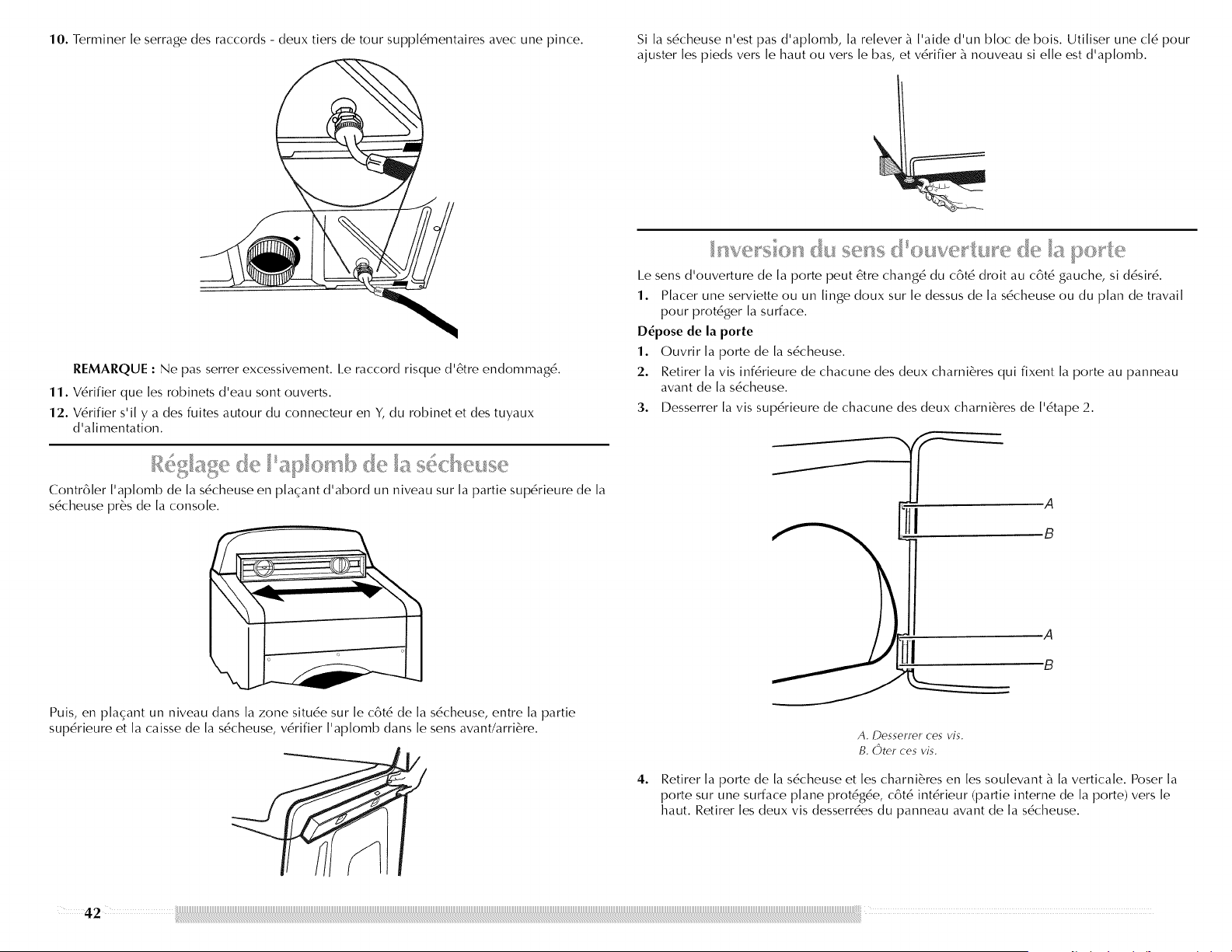
10.Terminerleserragedesraccords- deuxtiersdetoursuppl6mentairesavecunepince. Silas6cheusen'estpasd'aplomb,larelever_I'aided'unblocdebois.Utiliserunecl6pour
ajusterlespiedsverslehautouverslebas,etv6rifier_nouveausielleestd'aplomb.
REMARQUE : Ne pas serrer excessivement, l e raccord risque d'6tre endommag6.
11. V6rifier que [es robinets d'eau sont ouverts.
12. V6rifier s'i[ y a des fuites autour du connecteur en Y, du robinet et des tuyaux
d'a[imentation.
Contr61er I'aplomb de la s6cheuse en plaqant d'abord un niveau sur la partie sup6rieure de la
s6cheuse pr6s de la console.
Puis, en plaqant un niveau dans la zone situ6e sur le c6t6 de la s6cheuse, entre la partie
sup6rieure et la caisse de la s6cheuse, v6rifier I'aplomb dans le sens avant/arri6re.
I.e sens d'ouverture de la porte peut 6tre chang6 du c6t6 droit au c6t6 gauche, si d6sir6.
1. Placer une serviette ou un linge doux sur le dessus de la s6cheuse ou du plan de travail
pour prot6ger la surface.
D_pose de la porte
1. Ouvrir [a porte de [a s6cheuse.
2. Retirer [a vis inf6rieure de chacune des deux charni6res qui fixent [a porte au panneau
avant de [a s6cheuse.
3. Desserrer [avis sup6rieure de chacune des deux charni6res de ['6tape 2.
.A
B
A
"B
4.
A. DesselreF ces vJs.
B. (_)ter ces vis.
Retirer la porte de la s6cheuse et les charni6res en les soulevant _ la verticale. Poser la
porte sur une surface plane prot6g6e, c6t6 int6rieur (partie interne de la porte) vers le
haut. Retirer les deux vis desserr6es du panneau avant de la s6cheuse.
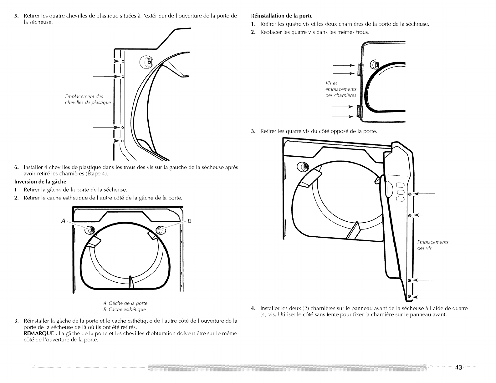
5°
Retirer les quatre chevilles de plastique situ6es _ I'ext6rieur de I'ouverture de la porte de
la s6cheuse.
!
Emplacement des
chevi//e._ de p/asdque
R6installation de la porte
1. Retirer les quatre vis et les deux charni6res de la porte de la s6cheuse.
2. Replacer [es quatre vis dans [es m6mes trous.
3. Retirer les quatre vis du c6t6 oppos6 de la porte.
6. Installer 4 chevi[[es de p[astique dans [es trous des vis sur [a gauche de [a s6cheuse apr6s
avoir retir6 [es charni6res (Etape 4).
Inversion de la g&che
1. Retirer [a g_che de [a porte de [a s6cheuse.
2. Retirer [e cache esth6tique de ['autre c6t6 de [a g_che de [a porte.
3°
A. Cgche de la porte
B. Cache esth6tique
R6insta[[er [a g&che de [a porte et [e cache esth6tique de ['autre c6t6 de ['ouverture de [a
porte de [a s6cheuse de [_ o_J i[s ont 6t6 retir6s.
REMARQUE : I_a g_che de [a porte et [es chevi[[es d'obturation doivent 6tre sur [e m6me
c6t6 de ['ouverture de [a porte.
Emplacement._
des vis
I
4. Installer les deux (2) charni6res sur le panneau avant de la s6cheuse _ I'aide de quatre
(4) vis. Utiliser le c6t6 sans fente pour fixer la charni6re sur le panneau avant.
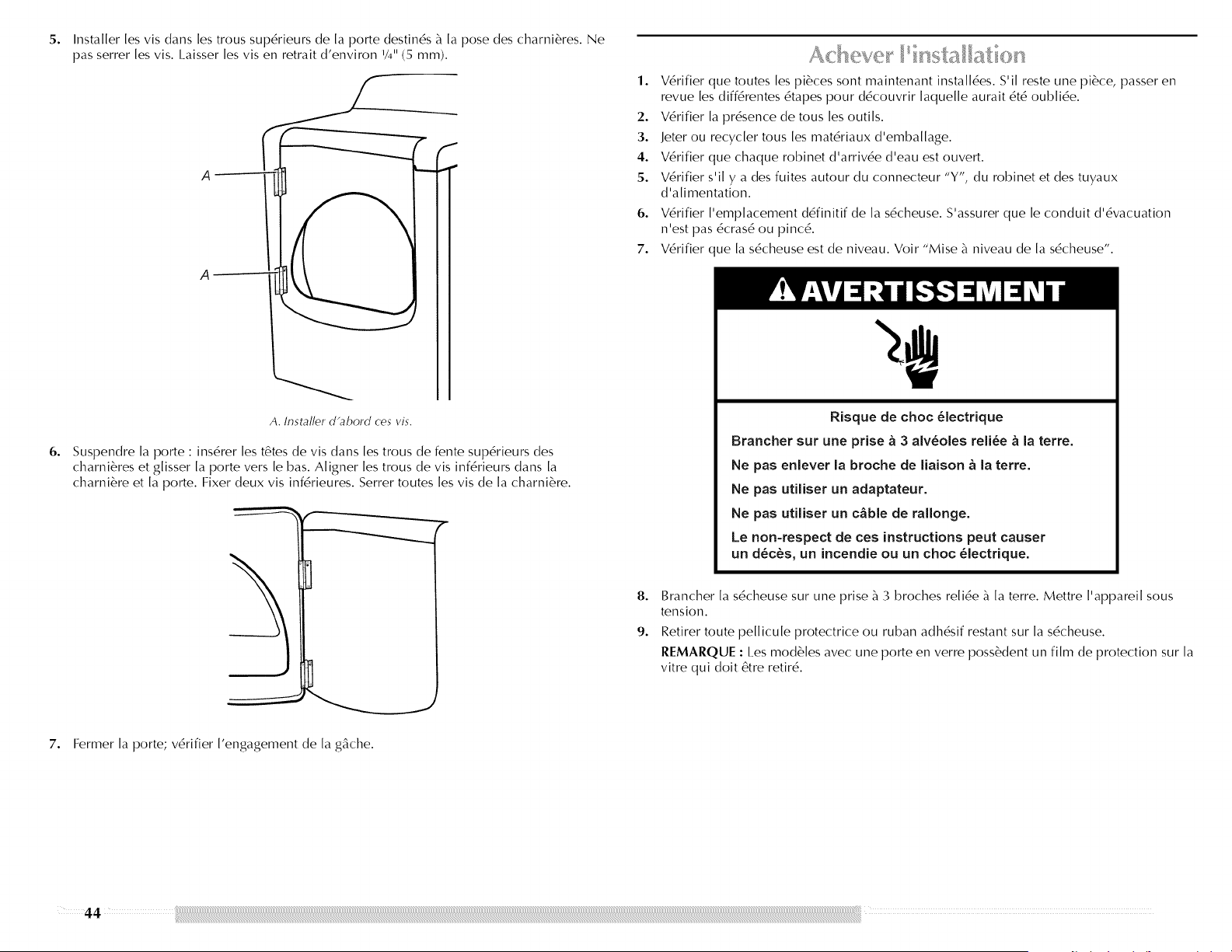
5o
6o
Installer les vis dans les trous sup6rieurs de la porte destin6s _ la pose des charni6res. Ne
pas serrer les vis. I.aisser les vis en retrait d'environ V4" (5 mm).
A
I
I
A. Installer d'abord ces vis.
f
Suspendre la porte : ins6rer les t6tes de vis dans les trous de fente sup6rieurs des
charni6res et glisser la porte vers le bas. Aligner les trous de vis inf6rieurs clans la
charni6re et la porte. Fixer deux vis inf6rieures. Serrer routes les vis de la charni6re.
7. Fermer la porte; v6rifier I'engagement de la g&che.
Ach : we nsf a at on
1. V6rifier que routes les pi6ces sont maintenant install6es. S'il reste une pi6ce, passer en
revue les diff6rentes 6tapes pour d6couvrir laquelle aurait 6t6 oubli6e.
2. V6rifier la pr6sence de tousles outils.
3. Jeter ou recycler tousles mat6riaux d'emballage.
4. V6rifier que chaque robinet d'arriv6e d'eau est ouvert.
5. V6rifier s'il y a des fuites autour du connecteur "Y', du robinet et des tuyaux
d'alimentation.
6. V6rifier I'emplacement d6finitif de la s6cheuse. S'assurer que le conduit d'6vacuation
n'est pas 6cras6 ou pinc6.
7. V6rifier que la s6cheuse est de niveau. Voir "Mise _ niveau de la s6cheuse'.
8°
9.
Risque de choc _lectrique
Brancher sur une prise & 3 aiv_oies reli_e & la terre.
Ne pas eniever la broche de liaison & la terre.
Ne pas utiiiser un adaptateur.
Ne pas utiiiser un c&bie de raiionge.
Le non-respect de ces instructions peut causer
un d_c_s, un incendie ou un choc _lectrique.
Brancher la s6cheuse sur une prise _ 3 broches reli6e _ la terre. Mettre I'appareil sous
tension.
Retirer toute pellicule protectrice ou ruban adh6sif restant sur la s6cheuse.
REMARQUE : Les mod61es avec une porte en verre poss&dent un film de protection sur la
vitre qui dolt 6tre retir6.
4 4
10.I.ire"Utilisationdelas6cheuse".
11.EssuyersoigneusementI'int6rieurdutambourdelas6cheuseavecunchiffonhumide
pour61iminer route trace de poussi6re.
12. Si vous habitez dans une r6gion o_J I'eau est dure, il est recommand6 d'utiliser un
adoucisseur d'eau afin de contr61er les accumulations de calcaire dans la s6cheuse. Apr6s
un certain temps, les accumulations de calcaire peuvent obstruer diff6rentes parties du
syst_'me d'eau, ce qui r6duira la performance du produit. Des accumulations excessives
de calcaire peuvent engendrer la n6cessit6 de remplacer des pi6ces ou de r6parer la
s6cheuse.
13. Tester le fonctionnement de la s6cheuse en s6lectionnant un programme minut6 avec
s6chage _ chaud et en mettant la s6cheuse en marche. Pour ce test, ne pas s61ectionner le
modificateur Air Fluff (air seulement).
14.
Si la s_cheuse ne d_marre pas, v_rifier ce qui suit :
• I.es commandes sont r6gl6es _ [a position de marche "On".
• I.e bouton de mise en marche a 6t6 fermement enfonc6
• I.a s6cheuse est branch6e sur une prise _ 3 broches re[i6e _ [a terre.
• I/a[imentation 6[ectrique est connect6e.
• I.es fusib[es sont intacts et serr6s, ou [e disjoncteur n'est pas d6c[ench6.
• I.a porte de [a s6cheuse est ferm6e.
Apr6s 5 minutes de fonctionnement, ouvrir [a porte de [a s6cheuse et voir s'i[ y a de [a
cha[eur. En cas de cha[eub annu[er [e programme et fermer [a porte. Si vous ne sentez pas
de cha[eub 6teindre [a s6cheuse et v6rifier si [e robinet d'arr6t de [a cana[isation d'arriv6e
de gaz est ouvert.
• Si [e robinet d'arr6t de [a cana[isation d'arriv6e de gaz est ferm6, ['ouvrib puis refaire
[e test des 5 minutes tel qu'indiqu6 ci-dessus.
• Si [e robinet d'arr6t de [a cana[isation d'arriv6e de gaz est ouvert, contacter un
technicien qua[ifi6.
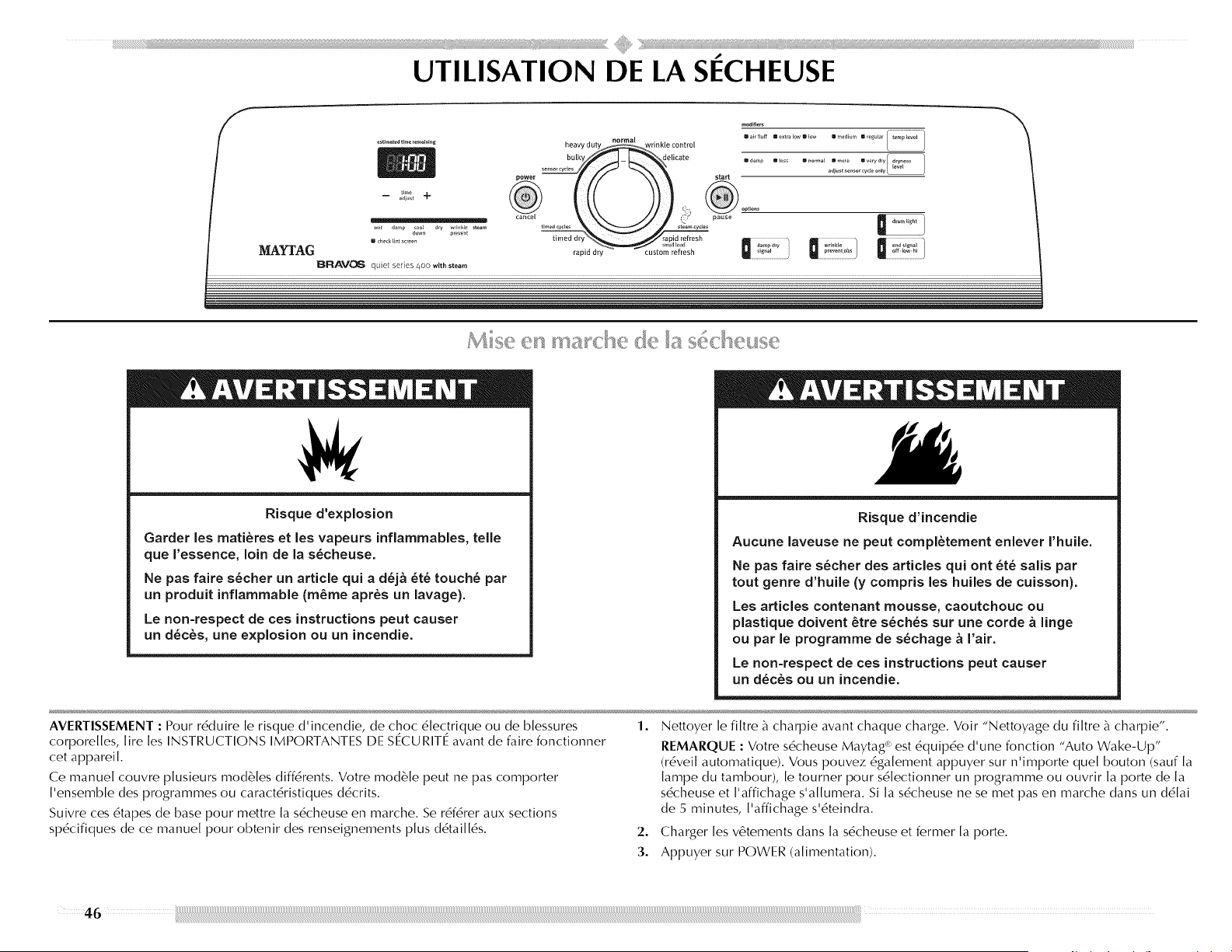
modifiers ..........................
heavy d_t_ _ri_kte _o_o_
bulky delicate = ..... / _%_# ]
p.... m(ess ano_mal mmo_e mverydry d_ness
se,lso_ cydes start adjust sensor cyde o_ly
- _;;';_ +
_revent
MAYFAG ..... ...............................................................
_ R AV_I6 q_ietseies4oowitbsteam
Risque d'explosion
Garder les mati_res et les vapeurs inflammables, telle
que I'essence, loin de la s_cheuse.
Ne pas faire s6cher un article quJ a d_j& 6t_ touch6 par
un produJt inflammable (m_me apr_s un lavage).
Le non=respect de ces instructions peut causer
un d_c_s, une explosion ou un incendie.
Risque d'incendie
Aucune laveuse ne peut compl_tement enlever I'huile.
Ne pas faire s_cher des articles quJ ont _t_ salis par
tout genre d'huile (y compris les huJles de cuisson).
Les articles contenant mousse, caoutchouc ou
plastJque doJvent _tre s_ch_s sur une corde & linge
ou par le programme de s_chage & Fair.
Le non-respect de ces instructions peut causer
un d_c_s ou un incendie.
AVERTISSEMENT : Pour r6duire le risque d'incendie, de choc 6lec_trique ou de blessures
corporelles, lire les INSTRUCTIONS IMPORTANTES I)E SECURITE avant de faire fonctionner
cet appareil.
Ce manuel couvre plusieurs modules diffdrents. Votre module peut ne pas comporter
I'ensemble des programmes ou caractdristiques d6crits.
Suivre ces drapes de base pour mettre la sdcheuse en marche. Se rdfdrer aux sections
spdcifiques de ce manuel pour obtenir des renseignements plus d6taill6s.
1.
Nettoyer le filtre b_charpie avant chaque charge. Voir "Nettoyage du filtre b_charpie".
REMARQUE : Votre s6cheuse Maytag _"est 6quipde d'une fonction "Auto Wake-Up"
(r6vei[ automatique). Vous pouvez 6ga[ement appuyer sur n'importe que[ bouton (sauf [a
[ampe du tambour), [e tourner pour s6[ectionner un programme ou ouvrir [a porte de [a
s6cheuse et ['affichage s'a[[umera. Si [a s6cheuse ne se met pas en marche dans un d6[ai
de 5 minutes, ['affichage s'6teindra.
2. Charger les v6tements dans la s6cheuse et fermer la porte.
3. Appuyer sur POWER (alimentation).
4
4,
Tourner le bouton au programme s61ectionn6. I_es pr6r6g[ages des programmes Sensor
(d6tection), Timed (minut6), ou Steam (vapeur) s'a[[umeront. I.a durde du programme
estimde en minutes (programme de d6tection) ou rde[[e (programme minut6) s'affichera.
REMARQUE : Une durde par d6faut est affichde [orsqu'un programme automatique est
s6[ectionn6. Au cours des premi6res minutes du processus de s6chage, [a durde du
programme peut varier automatiquement par rapport _ [a durde par d6faut en fonction du
volume et du type de tissu de [a charge. Vers [a fin du processus de s6chage, ['afficheur de
[a durde estimde s'ajustera de nouveau, indiquant [a durde de s6chage finale.
Utilisation d'un programme de d_tection
Appuyer sur POWER/CANCEl. (mise sous tension/annulation).
Tourner le bouton au programme de s6chage par d6tection d6sir6.
S61ectionner DRYNESS I.EVEI_ (degr6 de s6chage) pour ajuster le degr6 de s6chage
d6sir6 de [a charge. Au fur et _ mesure que [e programme s'ex6cute, [a commande
ddtecte [e degr6 de s6chage de [a charge et ajuste [a durde automatiquement se[on [e
degr6 d6sir6.
I.e prdr6g[age initial de tempdrature correspond au r6g[age recommand6 pour s6cher
des charges de diff6rents types de v6tements (voir "Programmes de d6tection"). Si
d6sir6, une autre temp6rature peut 6tre s6lectionnde pour s6cher [a charge _ un
r6glage de chaleur plus faible. #, la prochaine s61ection de ce programme, I'autre
temp6rature est m6morisde et affichde. I_a temp6rature d'origine (par d6faut) peut 6tre
res61ectionnde. I.es programmes Delicate (articles d61icats) et Bulky (articles
encombrants) n'offrent pas d'autre temp6rature.
S61ectionner les options d6sirdes.
Pour apporter des modifications Iors d'un programme de d_tection :
• Appuyer sur START/PAUSE (mise en marche/pause).
• Ajuster le degr6 de s6chage.
Idamp Iless II normal mmore m very dry I dryn,ess 1
adjust sensor cycle only
REMARQUE : I_ess6lections du degr6 de s6chage sont possibles uniquement Iors de
['uti[isation des programmes de ddtection.
Fonctionnement du syst_me de s_chage Sensi-Care TM
Des bandes de d6tection de I'humidit6 et des capteurs de tempdrature _ I'int6rieur du
tambour de la s6cheuse contrBlent la vitesse de s6chage de la charge, le degr6 de chaleur
de I'air et le degr6 de s6chage des v6tements. I.e syst_'me arr6te automatiquement le
programme pour gagner du temps et 6viter un s6chage excessif.
Utilisation d'un programme minut_
• Tourner le bouton au programme minut6 d6sir6.
Appuyer sur les fl6ches TIME ADJUST (r6g[age de [a durde) + (plus) ou - (moins)
jusqu'_ ce que [a durde de s6chage d6sirde s'affiche. Appuyer sur + (plus) ou - (moins)
et [a durde changera par tranche de 1 minute. Appuyer sans tel&chef sur + (plus)
ou - (moins) et [a durde changera par tranche de 5 minutes.
REMARQUE : I_a fonction Time Adjust (r6glage de la durde) peut 6tre utilisde
uniquement avec [es programmes Timed (minut6s) et Custom Refresh
(rafra?chissement personna[is6).
time
adjust 4"
Appuyer sur TEMP I.EVEI. (niveau de tempdrature) jusqu'_ ce que la tempdrature
d6sirde s'allume.
i air fluff II extra low Ill tow a medium II regular
REMARQUE : I_a fonction Temp Level (niveau de temp6rature) peut &tre utilisde
uniquement avec [es programmes Timed (minut6s) et Custom Refresh (rafra?chissement
personna[is6).
REMARQUE : I_ors d'un programme minut6, vous pouvez modifier [es r6g[ages de durde,
de temp6rature, de [a fonction Wrinkle Prevent (anti-froissement) et End Signal (signal de
fin de programme).
5. (ETAPE FACUI.TATIVE) Si d6sir6, s6[ectionner des OPTIONS. Pour plus de d6tai[s, voir
"Options".
6. (ETAPE FACUI_TATIVE) Si d6sir6, appuyer sur END SIGNAl_ (signal de fin de programme).
Un signal sera 6mis pour vous annoncer [a fin du programme. Pour plus de ddtai[s, voir
"Signal de fin de programme".
7. Appuyer sur START/PAUSE (mise en marche/pause). V6rifier que [a porte est fermde.
• Si on n'appuie pas sur Start dans [es 5 minutes qui suivent [e choix de programme, [a
s6cheuse s'arr6te automatiquement.
• Si I'on souhaite mettre fin _ votre programme de s6chage apr6s avoir appuy6 sur Start
(mise en marche), appuyer sur POWER/CANCEl. (mise sous tension/annulation).
Utilisation d'un programme vapeur
Appuyer sur POWER/CANCEl. (mise sous tension/annulation).
Tourner le bouton au programme Steam (vapeur) d6sir6.
Pour le programme Custom Refresh (rafra?chissement personnalis6), appuyer sur TIME
ADJUST + (plus) ou - (moins) jusqu'_ ce que [a durde de s6chage d6sirde s'affiche.
Appuyer sur + (plus) ou - (moins) et [a durde changera par tranche de 1 minute.
Appuyer sans tel&chef sur + (plus) ou - (moins) et [a durde changera par tranche de 5
minutes.
REMARQUE : l.es caractdristiques d'ajustement du programme minut6 ne peuvent
6tre utilisdes qu'avec les programmes minut6s et le programme de rafra_chissement
personnalis6.
time
m adjust 4"
• AppuyersurTEMPI.EVEI.(niveaudetemp6rature)jusqu'_cequelatemp6rature
d6sir6es'allume.
mairftuff mextraiow_low mmedium 8regular
REMARQUE : I)urant le programme Custom Refresh (rafra?chissement personnalis6), vous
pouvez modifier [es r6g[ages de dur6e et de temp6rature. Ouvrir [a porte ou appuyer sur
START/PAUSE (mise en marche/pause) pour faire une pause, ou appuyer sur POWER/
CANCEl. (mise sous tension/annu[ation) pour annu[er un programme.
Pour mettre la s6cheuse en pause ou I'arr_ter/! tout moment
Ouwir la porte ou appuyer sur START/PAUSE(raise en marche/pause). Appuyer sur POWER/
CANCEl_ (mise sous tension/annulation) pour annuler un programme.
Pour remettre la s_cheuse en marche
Fermer la porte. Appuyer sur START/PAUSE (rnise en marche/pause) jusqu'_ la rnise en
marche de la s6cheuse.
REMARQUE : I_e s6chage reprendra I_ o_ le programme a 6t6 interrompu si on referme la
porte et appuie sur Start dans [es 5 minutes qui suivent. Si [e programme est interrompu
pendant plus de 5 minutes, [a s6cheuse s'arr6te. S6[ectionner de nouveaux r6g[ages de
programme avant de remettre [a s6cheuse en marche.
Choisir le programme, le degr6 de s6chage et la temp6rature corrects pour la charge. Si un
programme de d6tection est en cours, I'affichage indique la dur6e estim6e du programme
alors que votre s6cheuse d6tecte automatiquement le degr6 de s6chage de votre charge. Si un
programme minut6 est en cours, I'afficheur indique la dur6e exacte en minutes restantes
jusqu'_ la fin du programme.
I.a p6riode de refroidissement fair culbuter la charge sans chaleur au cours des quelques
derni6res minutes de tousles programmes. I_a p6riode de refroidissement permet de
manipuler les charges plus facilement et r6duit le froissement. I.a dur6e de refroidissement
varie en fonction de la charge et du degr6 de s6chage.
Conseils de s_chage
• Suiwe les directives figurant sur l'6tiquette Iorsqu'elles sont disponibles.
Si d6sir6, ajouter une feuille d'assouplissant de tissu. Suiwe les instructions figurant sur
I'emballage.
Pour r6duire le froissement, enlever la charge de la s6cheuse aussitBt que le culbutage
cesse. Cette action est particuli6rement importante pour les tissus _ pressage permanent,
les tricots et les tissus synth6tiques.
Eviter de faire s6cher des v6tements de travail 6pais avec des tissus plus 16gers. II pourrait
en r6sulter un s6chage excessif des tissus plus 16gers et un r6tr6cissement ou froissement
accru.
Conseils pour les programmes
• On recommande de s6cher la plupart des charges en utilisant les pr6r6glages de
programme.
Consulter le tableau des pr6r6glages des programmes de d6tection, vapeur, ou minut6s (_
la section "Programmes") pour obtenir des informations sur les diverses charges de
s6chage.
I.a temp6rature de s6chage et le degr6 de s6chage sont pr6r6gl6s Iorsqu'on choisit un
programme automatique. On peut s6[ectionner un degr6 de s6chage diff6rent, en
fonction de [a charge, en appuyant sur Dryness et en choisissant More (plus), Normal
(normal), I.ess (moins), ou Damp (humide). I_a temp6rature pr6r6g[6e d'origine
correspond au r6g[age recommand6; cependant, vous pouvez s6[ectionner une autre
temp6rature de s6chage en appuyant sur TEMP I.EVEI. (niveau de temp6rature). Une
fois s6[ectionn6, [e nouveau r6g[age de cha[eur sera m6moris6 jusqu'_ [a
r6initia[isation _ [a temp6rature pr6r6g[6e d'origine. I_esprogrammes Delicate (articles
d6[icats) et Bulky (articles encombrants) ne permettent pas [a s6[ection d'une autre
temp6ratu re.
Si vous souhaitez ajuster la dur6e d'un programme minut6, appuyer sur TIME ADJUST
+ (plus) ou - (moins). Ajuster [a temp6rature d'un programme minut6 en appuyant sur
TEMP LEVEl_ (niveau de temp6rature) jusqu'_ ce que [a temp6rature d6sir6e soit
s6[ectionn6e.
REMARQUE : II est impossible de choisir un degr6 de s6chage avec les programmes
minut6s.
On peut suiwe l'6tat d'avancement de la s6cheuse grace aux t6moins lumineux du degr6 de
s6chage.
down prevent
Wet (mouill_)
l.e t6moin lumineux Wet (mouill6) s'allume au d6but d'un programme de d6tection si un
article mouill6 est d6tect6.
I.ors d'un programme de d6tection, si aucun article mouill6 n'est d6tect6 au bout
d'environ 5 minutes, [a s6cheuse passe directement au refroidissement. I_es indicateurs de
r6g[age Coo[ Down (refroidissement) et Wrinkle Prevent (anti-froissement) s'a[[umeront
s'i[s ont 6t6 s6[ectionn6s.
• I.ors d'un programme minut6, les articles mouill6s ne sont pas d6tect6s. I_a s6cheuse
continuera _ fonctionner pendant [a dur6e s6[ectionn6e et [e t6moin Wet (moui[[6)
s'a[[umera. I.e t6moin Damp (humide) ne s'a[[umera pas.
Damp (humide)
l.e t6moin lumineux [)amp (humide) s'allume lors d'un programme de d6tection lorsque le
linge est sec _ environ 80 %. Un signal de s6chage humide retentit s'il a 6t6 s61ectionn6. Voir
"Options".
Cool Down (refroidissement)
l.e t6moin lumineux Cool [)own (refroidissement) s'allume lors de la phase de refroidissement
du programme, l.e linge refroidit pour faciliter sa manipulation.
Dry (sec)
I.e t6moin Dry s'allume Iorsque le programme de s6chage est terrain6. Ce t6moin reste allure6
durant [e r6g[age Wrinkle Prevent (antifroissement).
48
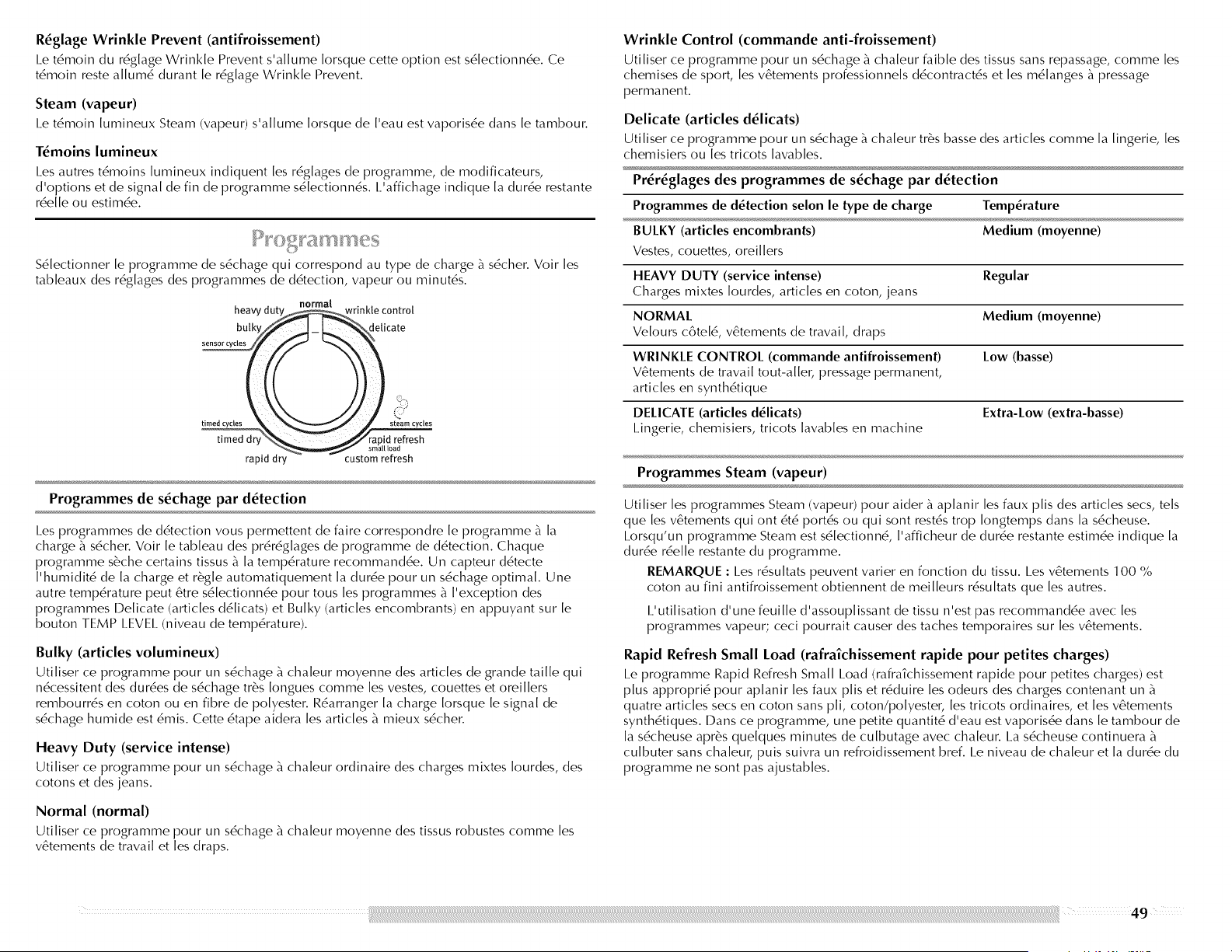
R_glage Wrinkle Prevent (antifroissement)
I_e t6moin du r6glage Wrinkle Prevent s'allume Iorsque cette option est s6lectionnde. Ce
t6moin reste allum6 durant le r6glage Wrinkle Prevent.
Steam (vapeur)
I.e t6moin lumineux Steam (vapeur) s'allume Iorsque de I'eau est vaporisde dans le tambour.
T_moins lumineux
I.es autres t6moins lumineux indiquent les r6glages de programme, de modificateurs,
d'options et de signal de fin de programme s61ectionn6s. I.'affichage indique la durde restante
rdelle ou estimde.
S6lectionner le programme de s6chage qui correspond au type de charge _ s6cher. Voir les
tableaux des r6g[ages des programmes de ddtection, vapeur ou minut6s.
normal
heavyd_inkle control
sensor cycles
timed cycles steam cycles
d refresh
rapid dry custom refresh
Programmes de s_chage par d_tection
I.es programmes de ddtection vous permettent de faire correspondre le programme _ la
charge _ s6cher. Voir [e tableau des pr6r6g[ages de programme de d6tection. Chaque
programme s6che certains tissus _ [a temp6rature recommandde. Un capteur d6tecte
['humidit6 de [a charge et r6g[e automatiquement [a durde pour un s6chage optimal. Une
autre temp6rature peut 6tre s6[ectionnde pour tous[es programmes _ I'exception des
programmes I::)e[icate (articles d6[icats) et Bulky (articles encombrants) en appuyant sur [e
bouton TEMP I.EVEI. (niveau de temp6rature).
Bulky (articles volumineux)
Utiliser ce programme pour un s6chage _ chaleur moyenne des articles de grande taille qui
ndcessitent des durdes de sdchage tr@s Iongues comme les vestes, couettes et oreillers
rembourr6s en coton ou en fibre de polyester. Rdarranger la charge Iorsque le signal de
s6chage humide est 6mis. Cette 6tape aidera les articles _ mieux s6cher.
Heavy Duty (service intense)
Uti[iser ce programme pour un s6chage _ cha[eur ordinaire des charges mixtes [ourdes, des
cotons et des jeans.
Normal (normal)
Utiliser ce programme pour un s6chage _ chaleur moyenne des tissus robustes comme les
v6tements de travail et [es draps.
Wrinkle Control (commande anti-froissement)
Utiliser ce programme pour un s6chage _ chaleur faible des tissus sans repassage, comme les
chemises de sport, [es v6tements professionne[s d6contract6s et [es m6[anges _ pressage
permanent.
Delicate (articles d_licats)
Utiliser ce programme pour un s6chage _ chaleur tr_s basse des articles comme la lingerie, les
chemisiers ou [es tricots [avab[es.
Pr_r_glages des programmes de s_chage par d_tection
Programmes de d_tection selon le type de charge Temperature
BULKY (articles encombrants) Medium (moyenne)
Vestes, couettes, oreillers
HEAVY DUTY (service intense) Regular
Charges mixtes Iourdes, articles en coton, jeans
NORMAL Medium (moyenne)
Velours c6te[6, v6tements de travail, draps
WRINKLE CONTROL (commande antifroissement) Low (basse)
V6tements de travail tout-a[[e_, pressage permanent,
articles en synthdtique
DELICATE (articles d_licats) Extra-Low (extra-basse)
I.ingerie, chemisiers, tricots [avab[es en machine
Programmes Steam (vapeur)
Utiliser les programmes Steam (vapeur) pour aider _ aplanir les faux plis des articles secs, tels
que [es v6tements qui ont 6t6 port6s ou qui sont rest6s trop [ongtemps dans [a s6cheuse.
I.orsqu'un programme Steam est s6[ectionn6, ['afficheur de durde restante estimde indique [a
durde rde[[e restante du programme.
REMARQUE : I_esr6su[tats peuvent varier en fonction du tissu. I.es v6tements 100 %
coton au fini antifroissement obtiennent de mei[[eurs r6su[tats que [es autres.
I.'utilisation d'une feuille d'assouplissant de tissu n'est pas recommandde avec les
programmes vapeur; ceci pourrait causer des taches temporaires sur les v6tements.
Rapid Refresh Small Load (rafralchissement rapide pour petites charges)
I.e programme Rapid Refresh Small I.oad (rafrakhissement rapide pour petites charges) est
plus appropri6 pour aplanir les faux plis et r6duire les odeurs des charges contenant un
quatre articles secs en coton sans pli, coton/polyestec les tricots ordinaires, et les v6tements
synth6tiques. Dans ce programme, une petite quantit6 d'eau est vaporisde dans le tambour de
la s6cheuse apr6s quelques minutes de culbutage avec chaleur. I_a s6cheuse continuera
culbuter sans chaleuc puis suivra un refroidissement bref. I.e niveau de chaleur et la durde du
programme ne sont pas ajustables.
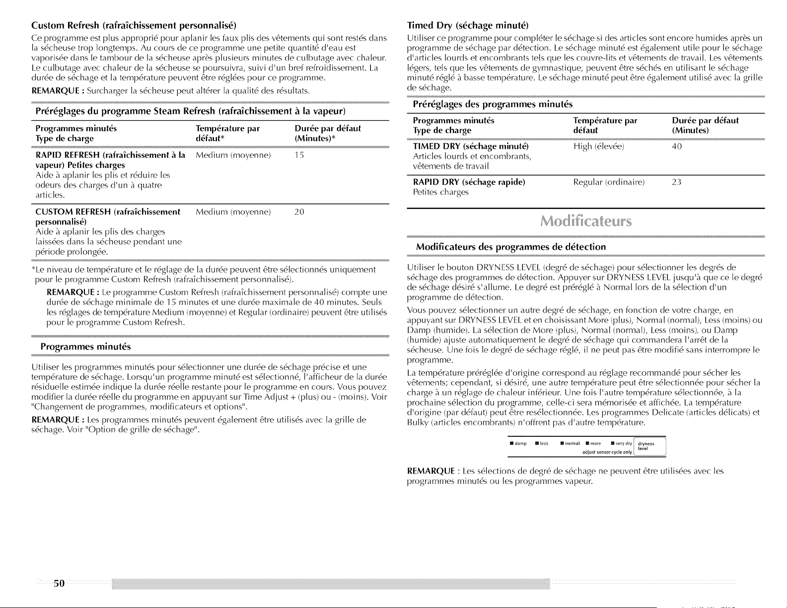
Custom Refresh (rafralchlssement personnalis_)
Ce programme est plus approprid pour aplanir les faux plis des v6tements qui sont rest6s dans
la sdcheuse trop Iongtemps. Au cours de ce programme une petite quantit6 d'eau est
vaporisde dans le tambour de la sdcheuse apr6s plusieurs minutes de culbutage avec chaleur.
I.e culbutage avec chaleur de la sdcheuse se poursuivra, suivi d'un bref refroidissement. I.a
durde de sdchage et la tempdrature peuvent 6tre rdgldes pour ce programme.
REMARQUE : Surcharger la sdcheuse peut alt6rer la qualit6 des rdsultats.
Pr_r_glages du programme Steam Refresh (rafralchissement _ la vapeur)
Programmes minutes Temperature par Dur_e par d_faut
Type de charge d_faut* (Minutes)*
RAPID REFRESH (rafraichissement _ la Medium (moyenne) 15
vapeur) Petites charges
Aide _ aplanir les plis et r6duire les
odeurs des charges d'un _ quatre
articles.
CUSTOM REFRESH (rafraichissement
personnalis_)
Aide _ aplanir les plis des charges
laissdes dans la s6cheuse pendant une
p6riode prolongde.
Medium (moyenne) 20
*l.e niveau de temp6rature et le r6glage de la durde peuvent 6tre s6lectionn6s uniquement
pour [e programme Custom Refresh (rafra?chissement personna[is6).
REMARQUE : I_e programme Custom Refresh (rafra?chissement personna[is6) compte une
durde de s6chage minima[e de 15 minutes et une durde maxima[e de 40 minutes. Seu[s
[es r6g[ages de temp6rature Medium (moyenne) et Regular (ordinaire) peuvent 6tre uti[is6s
pour [e programme Custom Refresh.
Programmes minutes
Utiliser les programmes minut6s pour s6lectionner une durde de s6chage pr6cise et une
temp6rature de s6chage. I.orsqu'un programme minut6 est s6[ectionn6, ['afficheur de [a durde
r6sidue[[e estimde indique [a durde rde[[e restante pour [e programme en cours. Vous pouvez
modifier [a durde rde[[e du programme en appuyant sur Time Adjust + (plus) ou - (moins). Voir
"Changement de programmes, modificateurs et options".
REMARQUE : I.es programmes minut6s peuvent 6ga[ement 6tre uti[is6s avec [a grille de
s6chage. Voir "Option de grille de s6chage".
Timed Dry (s_chage minute)
Utiliser ce programme pour compl6ter le s6chage si des articles sont encore humides apr6s un
programme de s6chage par d6tection. I.e s6chage minut6 est 6ga[ement utile pour [e s6chage
d'artic[es [ourds et encombrants te[s que [es couvre-[its et v6tements de travail I.es v6tements
[6gers, te[s que [es v6tements de gymnastique, peuvent 6tre s6ch6s en uti[isant [e s6chage
minut6 r6g[6 _ basse temp6rature. I.e s6chage minut6 peut 6tre 6ga[ement uti[is6 avec [a grille
de s6chage.
Pr_r_glages des programmes minutes
Programmes minutes Temperature par Dur_e par d_faut
Type de charge d_faut (Minutes)
TIMED DRY (s_chage minute) High (6[evde) 40
Articles [ourds et encombrants,
v6tements de travail
RAPID DRY (s_chage rapide) Regular (ordinaire) 23
Petites charges
Modificateurs des programmes de d_tection
Utiliser le bouton DRYNESS I_EVEI_(degr6 de s6chage) pour s6lectionner les degr6s de
s6chage des programmes de d6tection. Appuyer sur DRYNESS I_EVEI_jusqu'_ que ce [e degr6
de s6chage d6sir6 s'a[[ume. I.e degr6 est pr6r6g[6 _ Normal [ors de [a s6[ection d'un
programme de d6tection.
Vous pouvez s6[ectionner un autre degr6 de s6chage, en fonction de votre charge, en
appuyant sur I)RYN ESS I_EVEI. et en choisissant More (plus), Normal (normal), I_ess (moins) ou
I)amp (humide). I_a s6[ection de More (plus), Normal (normal), I_ess (moins), ou I)amp
(humide) ajuste automatiquement [e degr6 de s6chage qui commandera ['arr6t de [a
s6cheuse. Une fois [e degr6 de s6chage r6g[6, i[ ne peut pas 6tre modifi6 sans interrompre [e
programme.
I.a temp6rature prdr6g[de d'origine correspond au r6g[age recommand6 pour s6cher [es
v6tements; cependant, si d6sir6, une autre tempdrature peut 6tre s6[ectionnde pour s6cher [a
charge _ un r6g[age de cha[eur inf6rieur. Une fois ['autre temp6rature s6[ectionnde, _ [a
prochaine s6[ection du programme, ce[[e-ci sera m6morisde et affichde. I_atemp6rature
d'origine (par d6faut) peut 6tre res6[ectionnde. I_esprogrammes I)e[icate (articles d6[icats) et
Bulky (articles encombrants) n'offrent pas d'autre tempdrature.
U damp Im less m normal Ill more m very dry dryness
adjust sensor cycle only
REMARQUE : I_ess6lections de degr6 de s6chage ne peuvent 6tre utilisdes avec les
programmes minut6s ou [es programmes vapeur.
50
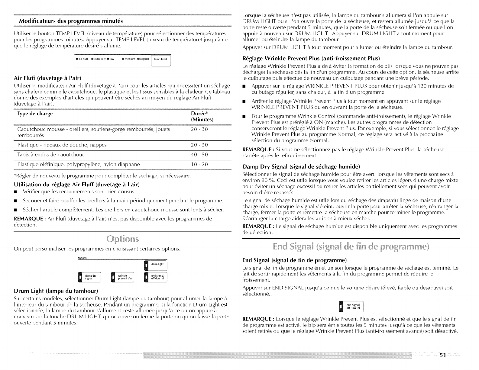
Modificateurs des programmes minutes
Utiliser le bouton TEMP I.EVEI_ (niveau de tempdrature) pour s6lectionner des tempdratures
pour [es programmes minutds. Appuyer sur TEMP I.EVEI. (niveau de tempdrature) jusqu'b_ ce
que [e r6g[age de tempdrature d6sir6 s'a[[ume.
Imairfluff mextra(owm(ow mmedium Imregu(ar
Air Fluff (duvetage & I'air)
Uti[iser [e modificateur Air Fluff (duvetage _ ['air) pour [es articles qui n6cessitent un s6chage
sans cha[eur comme [e caoutchouc, [e p[astique et [es tissus sensib[es b_[a cha[eur. Ce tableau
donne des exemp[es d'artic[es qui peuvent 6tre s6ch6s au moyen du r6g[age Air Fluff
(duvetage _ ['air).
Type de charge Dur_e*
(Minutes)
Caoutchouc mousse - oreillers, soutiens-gorge rembourr6s, jouets 20 - 30
rembourr6s
P[astique - rideaux de douche, nappes 20 - 30
Tapis b_endos de caoutchouc 40 - 50
P[astique o[dfinique, po[ypropy[_ne, nylon diaphane 10 - 20
*R6g[er de nouveau [e programme pour comp[6ter [e s6chage, si n6cessaire.
Utillsation du r_glage Air Fluff (duvetage _. I'air)
• V6rifier que [es recouvrements sont bien cousus.
• Secouer et faire bouffer [es orei[[ers b_[a main pdriodiquement pendant [e programme.
• S6cher ['article comp[_tement. I.es orei[[ers en caoutchouc mousse sont [ents b_s6cher.
REMARQUE : Air Fluff (duvetage b_['air) n'est pas disponib[e avec [es programmes de
detection.
On peut personnaliser les programmes en choisissant certaines options.
options
Drum Light (lampe du tambour)
Sur certains modules, s6lectionner Drum I.ight (lampe du tambour) pour allumer la lampe b_
['int6rieur du tambour de [a s6cheuse. Pendant un programme, si [a fonction Drum I.ight est
s6[ectionnde, [a [ampe du tambour s'a[[ume et reste a[[umde jusqu'_ ce qu'on appuie b_
nouveau sur [a touche DRUM LIGHT, qu'on ouvre ou ferme [a porte ou qu'on [aisse [a porte
ouverte pendant 5 minutes.
I.orsque [a s6cheuse n'est pas uti[isde, [a [ampe du tambour s'a[[umera si ['on appuie sur
DRUM LIGHT ou si ['on ouvre [a porte de [a s6cheuse, et restera a[[umde jusqu'b_ ce que [a
porte reste ouverte pendant 5 minutes, que [a porte de [a s6cheuse soit fermde ou que ['on
appuie b_nouveau sur DRUM LIGHT. Appuyer sur DRUM I.IGHT b_tout moment pour
a[[umer ou 6teindre [a [ampe du tambour.
Appuyer sur DRUM I.IGHT b_tout moment pour a[[umer ou dteindre [a [ampe du tambour.
R_glage Wrinkle Prevent Plus (anti-froissement Plus)
I.e r6glage Wrinkle Prevent Plus aide _ 6viter la formation de plis Iorsque vous ne pouvez pas
d6charger la s6cheuse d6s la fin d'un programme. Au cours de cette option, la s6cheuse arr6te
le culbutage puis effectue de nouveau un culbutage pendant une br_ve p6riode.
• Appuyer sur le r6glage WRINKI.E PREVENT PI.US pour obtenir jusqu'_ 120 minutes de
culbutage r6gulie_, sans chaleur, _ la fin d'un programme.
Arr6ter le r6glage Wrinkle Prevent Plus b_tout moment en appuyant sur le r6glage
WRINKI.E PREVENT PI.US ou en ouvrant [a porte de [a s6cheuse.
Pour le programme Wrinkle Control (commande anti-froissement), le r6glage Wrinkle
Prevent Plus est pr6r6g[6 _ ON (marche). Les autres programmes de d6tection
conserveront [e r6g[age Wrinkle Prevent Plus. Par exemp[e, si vous s6[ectionnez [e r6g[age
Wrinkle Prevent Plus au programme Normal, ce r6g[age sera activ6 b_[a prochaine
s6[ection du programme Normal
REMARQUE : Si vous ne s6lectionnez pas le r6glage Wrinkle Prevent Plus, la s6cheuse
s'arr6te apr@s [e refroidissement.
Damp Dry Signal (signal de s_chage humide)
S6lectionner le signal de s6chage humide pour 6tre averti Iorsque les v6tements sont secs b_
environ 80 %. Ceci est utile [orsque vous vou[ez retirer [es articles [6gers d'une charge mixte
pour 6viter un s6chage excessif ou retirer [es articles partie[[ement secs qui peuvent avoir
besoin d'etre repass6s.
I.e signal de s6chage humide est utile [ors du s6chage des draps/du [inge de maison d'une
charge mixte. I.orsque [e signal s'6teint, ouvrir [a porte pour arr6ter [a s6cheuse, rdarranger [a
charge, fermer [a porte et remettre [a s6cheuse en marche pour terminer [e programme.
Rdarranger [a charge aidera [es articles b_mieux s6cher.
REMARQUE : I.e signal de s6chage humide est disponib[e uniquement avec [es programmes
de ddtection.
End Signal (signal de fin de programme)
I.e signal de fin de programme 6met un son Iorsque le programme de s6chage est terrain6. I.e
fait de sortir rapidement [es v6tements b_[a fin du programme permet de r6duire [e
froissement.
Appuyer sur END SIGNAl. jusqu'b_ ce que le volume d6sir6 (6[ev6, faib[e ou d6sactiv6) soit
s6[ectionn6..
II 1
REMARQUE : I_orsque le r6glage Wrinkle Prevent Plus est s6lectionn6 et que le signal de fin
de programme est activ6, [e bip sera 6mis routes [es 5 minutes jusqu'b_ ce que [es v6tements
soient retir6s ou que [e r6g[age Wrinkle Prevent Plus (anti-froissement avanc6) soit d6sactiv6.
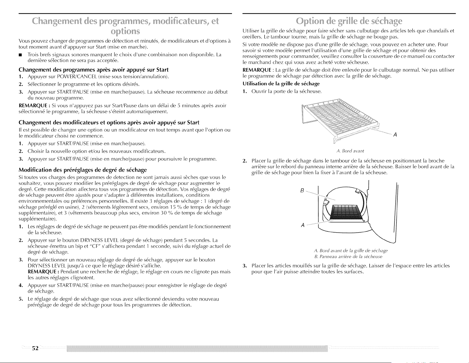
Vouspouvezchangerdeprogrammesded6tectionetminut6s,demodificateursetd'optionsb_
tout moment avant d'appuyer sur Start (mise en marche).
• Trois brefs signaux sonores marquent [e choix d'une combinaison non disponib[e. I.a
derni6re s6[ection ne sera pas accept6e.
Changement des programmes apr_s avoir appuy_ sur Start
1. Appuyer sur POWER/CANCEl. (mise sous tension/annu[ation).
2. S6[ectionner [e programme et[es options d6sir6s.
3. Appuyer sur START/PAUSE (mise en marche/pause). I.a s6cheuse recommence au d6but
du nouveau programme.
REMARQUE : Si vous n'appuyez pas sur Start/Pause dans un d6[ai de 5 minutes apr6s avoir
s6[ectionn6 [e programme, [a s6cheuse s'@eint automatiquement.
Changement des modificateurs et options apr_s avoir appuy_ sur Start
I[ est possible de changer une option ou un modificateur en tout temps avant que ['option ou
[e modificateur choisi ne commence.
1. Appuyer sur START/PAUSE (mise en marche/pause).
2. Choisir [a nouve[[e option et/ou [es nouveaux modificateurs.
3. Appuyer sur START/PAUSE (mise en marche/pause) pour poursuivre [e programme.
Modification des pr_r_glages de degr_ de s_chage
Si routes vos charges des programmes de detection ne sont jamais aussi s6ches que vous [e
souhaitez, vous pouvez modifier [es pr6r6g[ages de degr6 de s6chage pour augmenter [e
degr6. Cette modification affectera tous vos programmes de d6tection. Vos r6g[ages de degr6
de s6chage peuvent @re ajust6s pour s'adapter b_diff6rentes installations, conditions
environnementa[es ou pr6f6rences personne[[es. I[ existe 3 r6g[ages de s6chage : 1 (degr6 de
s6chage pr6r6g[6 en usine), 2 (v6tements [6g6rement secs, environ 15 % de temps de s6chage
supp[6mentaire), et 3 (v@ements beaucoup plus secs, environ 30 % de temps de s6chage
supp[6mentaire).
1. I.es r6g[ages de degr6 de s6chage ne peuvent pas @re modifi6s pendant [e fonctionnement
de [a s6cheuse.
2. Appuyer sur [e bouton DRYNESS I.EVEI. (degr6 de s6chage) pendant 5 secondes. La
s6cheuse 6mettra un bip et "CF" s'affichera pendant 1 seconde, suivi du r6g[age actue[ de
degr6 de s6chage.
3. Pour s6[ectionner un nouveau r6g[age de degr6 de s6chage, appuyer sur [e bouton
DRYNESS I_EVEI_jusqu'b_ ce que [e r6g[age d6sir6 s'affiche.
REMARQUE : Pendant une recherche de r6g[age, [e r6g[age en cours ne c[ignote pas mais
[es autres r6g[ages c[ignotent.
4. Appuyer sur START/PAUSE (mise en marche/pause) pour enregistrer [e r6g[age de degr6
de s6chage.
5. I.e r6g[age de degr6 de s6chage que vous avez s6[ectionn6 deviendra votre nouveau
pr6r6g[age de degr6 de s6chage pour tous[es programmes de d@ection.
+,,,s, )/_
Utiliser [a grille de s6chage pour faire s6cher sans culbutage des articles tels que chandails et
orei[[ers. I.e tambour toume, mais [a gri[[e de s6chage ne bouge pas.
Si votre mod6le ne dispose pas d'une grille de s6chage, vous pouve£ en acheter une. Pour
savoir si votre mod6[e permet ['uti[isation d'une gri[[e de s6chage et pour obtenir des
renseignements pour commander, veui[[e£ consu[ter [a couverture de ce manue[ ou contacter
[e marchand che£ qui vous ave£ achet6 votre s6cheuse.
REMARQUE : La gri[[e de s6chage doit 6tre en[ev6e pour [e cu[butage normal Ne pas uti[iser
[e programme de s6chage par d6tection avec [a grille de s6chage.
Utilisation de la grille de s_chage
1. Ouwir [a porte de [a s6cheuse.
A. Bord avant
2. Placer la grille de s6chage dans le tambour de [a s6cheuse en positionnant [a broche
arri6re sur [e rebord du panneau interne arri6re de [a s6cheuse. Baisser [e bord avant de [a
grille de s6chage pour bien [a fixer b_['avant de [a s6cheuse.
I
3.
A. Bord avant de la grille de sdchage
B. Panneau arri6re de la sdcheuse
Placer [es articles moui[[6s sur [a grille de s6chage. I.aisser de ['espace entre [es articles
pour que ['air puisse atteindre routes [es surfaces.
52
REMARQUE : Ne pas laisser un article pendre par-dessus le bord de la grille de s6chage. 8. Appuyer sur START/PAUSE (mise en marche/pause).
Ce tableau montre des exemp[es d'artic[es qui peuvent 6tre s6ch6s sur une grille et indique [e
programme, [e r6g[age de temp6rature et [a dur6e de s6chage sugg6r6s. I.a dur6e de s6chage
r6e[[e d6pendra du degr6 d'humidit6 retenue dans [es articles.
S_chage sur grille R_glage Temp. Dur_e*
(minutes)
Chandails en laine S6chage minut6 Basse 60
@irer _ [a tai[[e norma[e et 6taler
plat sur [a grille de s6chage.
Jouets rembourr_s ou oreillers S6chage minut6 Basse 60
Rembourrage de coton ou de
po[yester
Jouets rembourr_s ou oreillers S6chage minut6 Air seu[ement 90
Rembourrage en caoutchouc mousse (sans cha[eur)
Chaussures de tennis ou de toile S6chage minut6 Air seu[ement 90
(sans cha[eur)
*(R6g[er de nouveau [a dur6e pour comp[6ter [e s6chage, si n6cessaire.
4. Fermer la porte.
5. Appuyer sur le bouton POWER/CANCEl. (mise sous tension/annulation).
6. S61ectionner un programme de s6chage minut6 et une temp6rature (voir le tableau
suivant). I.es articles contenant de la mousse, du caoutchouc ou du plastique doivent 6tre
s6ch6s sur une corde _ linge ou en utilisant le r6glage de temp6rature Air Fluff (duvetage
Pair).
7. Vous devez s61ectionner une dur6e en appuyant sur TIME ADJUST + (plus) ou - (moins).
R6gler de nouveau la dur6e pour compl6ter le s6chage, si n6cessaire. Consulter le tableau
suivant.
P
ENTRETIEN DE LA SECHEUSE
/
Eviter de laisser des 616ments qui pourraient obstruer le d6bit de combustion et emp6cher une
bonne ventilation autour de la s6cheuse.
Risque d'explosion
Garder les mati_res et les vapeurs inflammables, telle
que I'essence, loin de la s_cheuse.
Placer la s_cheuse au moJns 46 cm (18 po) au-dessus
du piancher pour une installation darts un garage.
Le non-respect de ces instructions peut causer
un d_c_s, une explosion ou un incendie.
..... ....... ,,,__ _
.............. , ,,_£__, _.
Nettoyer le filtre b_charpie avant chaque charge. I.e tableau de commande comporte un
tdmoin lumineux pour vous rappeler de nettoyer le filtre b_charpie avant chaque charge. Un
filtre obstru6 de charpie peut augmenter la durde de s6chage.
IMPORTANT :
• Ne pas faire fonctionner la s6cheuse avec un filtre _ charpie d6plac6, endommag6,
bloqu6, ou manquant. Une telle action peut causer une surchauffe ou des dommages _ la
s6cheuse et aux tissus.
• Si de la charpie tombe dans la s6cheuse au moment du retrait du filtre, v6rifier le conduit
d'6vacuation et retirer la charpie.
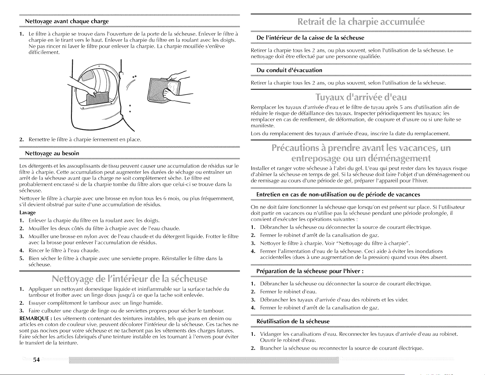
Nettoyage avant chaque charge
1.
I.e filtre _ charpie se trouve dans I'ouverture de la porte de la s6cheuse. Enlever le filtre
charpie en [e tirant vers [e haut. En[ever [a charpie du fi[tre en [a rou[ant avec [es doigts.
Ne pas rincer ni [aver [e fi[tre pour en[ever [a charpie. I.a charpie moui[[6e s'en[6ve
diffici [ement.
De l'int6rieurde lacaissede las6cheuse
Retirer [a charpie tous [es 2 ans, ou plus souvent, se[on ['uti[isation de [a s6cheuse. Le
nettoyage dolt 6tre effectu6 par une personne qua[ifi6e.
Du conduit d'6vacuation
Retirer [a charpie tous[es 2 ans, ou plus souvent, se[on ['uti[isation de [a s6cheuse.
2. Remettre le filtre _ charpie fermement en place.
Nettoyage au besoin
I.es d6tergents et les assouplissants de tissu peuvent causer une accumulation de r6sidus sur le
filtre _ charpie. Cette accumulation peut augmenter les dur6es de s6chage ou entraTner un
arr6t de la s6cheuse avant que la charge ne soit compl6tement s6che. I.e filtre est
probablement encrass6 si de la charpie tombe du filtre alors que celui-ci se trouve clans la
s6cheuse.
Nettoyer le filtre _ charpie avec une brosse en nylon tousles 6 mois, ou plus fr6quemment,
s'il devient obstru6 par suite d'une accumulation de r6sidus.
Lavage
1. Enlever la charpie du filtre en la roulant avec les doigts.
2. Mouiller les deux c6t6s du filtre _ charpie avec de I'eau chaude.
3. Mouiller une brosse en nylon avec de I'eau chaude et du d6tergent liquide. Frotter le filtre
avec la brosse pour enlever I'accumulation de r6sidus.
Rincer le filtre _ I'eau chaude.4.
5.
Bien s6cher le filtre _ charpie avec une serviette propre. R6installer le filtre dans la
s6cheuse.
1. Appliquer un nettoyant domestique Iiquide et ininflammable sur la surface tach6e du
tambour et frotter avec un linge doux jusqu'_ ce que la tache soit enlev6e.
2. Essuyer compl6tement le tambour avec un linge humide.
3. Faire culbuter une charge de linge ou de serviettes propres pour s6cher le tambour.
REMARQUE : I_es v6tements contenant des teintures instables, tels que jeans en denim ou
articles en coton de couleur vive, peuvent d6colorer I'int6rieur de la s6cheuse. Ces taches ne
sont pas nocives pour votre s6cheuse et ne tacheront pas les v6tements des charges futures.
Faire s6cher les articles fabriqu6s d'une teinture instable en les tournant _ I'envers pour 6viter
le transfert de la teinture.
£
Rernplacer les tuyaux d'arriv/e d'eau et le filtre de tuyau apr6s 5 ans d'utilisation afin de
r6duire le risque de d6faillance des tuyaux. Inspecter p6riodiquement les tuyaux; les
remplacer en cas de renflement, de d6formation, de coupure et d'usure ou si une fuite se
manifeste.
I.ors du remplacement des tuyaux d'arriv6e d'eau, inscrire la date du remplacement
_;Ni¢_'TON_{)qTI?@()I_ RI% {7_ _I_: I_' {;-t%'1_c{
.......... I'y " "* ""['ii ................ [7 .......
Installer et ranger votre s6cheuse i I'abri du gel. I_'eau qui peut rester dans les tuyaux risque
d'abTmer la s6cheuse en temps de gel. Si la s6cheuse dolt faire I'objet d'un d6m6nagement ou
de remisage au cours d'une p6riode de gel, pr6parer I'appareil pour I'hiver.
Entretien en cas de non-utilisation ou de p6riode de vacances
On ne dolt faire fonctionner la s6cheuse que Iorsqu'on est pr6sent sur place. Si I'utilisateur
dolt partir en vacances ou n'utilise pas la s6cheuse pendant une p6riode prolong6e, il
convient d'ex6cuter les op6rations suivantes :
1. D6brancher la s6cheuse ou d6connecter la source de courant 61ectrique.
2. Fermer le robinet d'arr6t de la canalisation de gaz.
3. Nettoyer le filtre _ charpie. Voir "Nettoyage du filtre _ charpie'.
4. Fermer I'alimentation d'eau de la s6cheuse. Ceci aide _ 6viter les inondations
accidentelles (dues _ une augmentation de la pression) quand vous 6tes absent.
Pr6paration de la s6cheuse pour I'hiver :
1. I)6brancher la s6cheuse ou d6connecter la source de courant 6lectrique.
2. Fermer [e robinet d'eau.
3. D6brancher [es tuyaux d'arriv6e d'eau des robinets et [es vider.
4. Fermer [e robinet d'arr6t de [a cana[isation de gaz.
R6utilisation de la s6cheuse
1. Vidanger les canalisations d'eau. Reconnecter les tuyaux d'arriv6e d'eau au robinet
Ouvrir le robinet d'eau.
2. Brancher la s6cheuse ou reconnecter la source de courant 61ectrique.
5 4
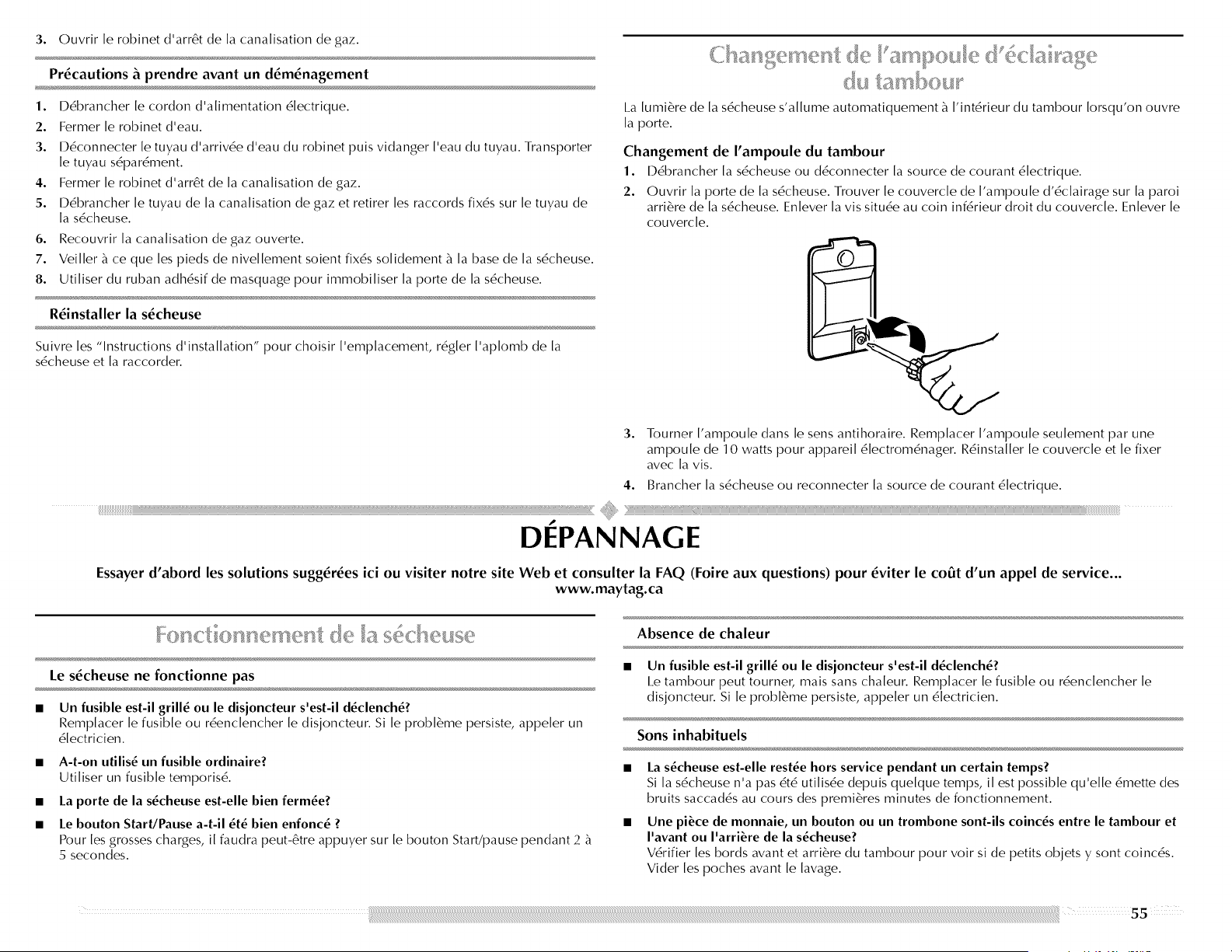
3. Ouvrir le robinet d'arr6t de la canalisation de gaz.
Precautions _ prendre avant un d_m_nagement
1. D6brancher le cordon d'alirnentation 6lectrique.
2. Fermer le robinet d'eau.
3. D6connecter le tuyau d'arriv6e d'eau du robinet puis vidanger I'eau du tuyau. Transporter
le tuyau s6par6ment.
4. Fermer le robinet d'arr6t de la canalisation de gaz.
5. D6brancher le tuyau de la canalisation de gazet retirer les raccords fix6s sur le tuyau de
la s6cheuse.
6. Recouvrir la canalisation de gaz ouverte.
7. Veiller _ ce que les pieds de nivellement soient fix6s solidement _ la base de la s6cheuse.
8. Utiliser du ruban adh6sif de masquage pour immobiliser la porte de la s6cheuse.
R_installer la s_cheuse
Suivre les "Instructions d'installation" pour choisir I'emplacement, r6gler I'apIomb de la
s6cheuse et la raccorder.
I.a lumi6re de la s6cheuse s'allume automatiquement _ I'int6rieur du tambour Iorsqu'on ouvre
la porte.
Changement de I'ampoule du tambour
1. D6brancher la s6cheuse ou d6connecter la source de courant 6lectrique.
2. Ouvrir [a porte de [a s6cheuse. Trouver [e couverc[e de ['ampoule d'6c[airage sur [a paroi
arri6re de [a s6cheuse. En[ever [avis situ6e au coin inf6rieur droit du couverc[e. En[ever [e
couvercle.
3. Tourner I'ampoule dans le sens antihoraire. Remplacer I'ampoule seulement par une
ampoule de 10 watts pour appareil 61ectrom6nager. R6installer le couvercle et le fixer
avec la vis.
4. Brancher la s6cheuse ou reconnecter la source de courant 6lectrique.
,p
DEPANNAGE
Essayer d'abord les solutions sugg_r_es ici ou visiter notre site Web et consulter la FAQ (Foire aux questions) pour _viter le co0t d'un appel de service...
www.maytag.ca
Le s_cheuse ne fonctionne pas
Un fusible est-il grill_ ou le disjoncteur s'est-il d_clench_?
Rernplacer le fusible ou r6enclencher le disjoncteur. Si le probl_rne persiste, appeler un
61ectricien.
• A-t-on utilis_ un fusible ordinaire?
Utiliser un fusible temporis6.
• La porte de la s_cheuse est-elle bien ferrule?
• Le bouton Start/Pause a-t-il _t_ bien enfonc_ ?
Pour [es grosses charges, i[ faudra peut-6tre appuyer sur [e bouton Start/pause pendant 2
5 secondes.
Absence de chaleur
• Un fusible est-il grill_ ou le disjoncteur s'est-il d_clench_?
I.e tambour peut tournec rnais sans chaleur. Rernplacer le fusible ou r6enclencher le
disjoncteur. Si le probl6me persiste, appeler un 61ectricien.
Sons inhabituels
La s_cheuse est-elle rest_e hors service pendant un certain temps?
Si la s6cheuse n'a pas 6t6 utilis6e depuis quelque temps, il est possible qu'elle 6rnette des
bruits saccad6s au cours des premi6res minutes de fonctionnement.
Une piece de monnaie, un bouton ou un trombone sont-ils coinc_s entre le tambour et
I'avant ou I'arri_re de la s_cheuse?
V6rifier les bords avant et arri6re du tambour pour voir si de petits objets y sont coinc6s.
Vider les poches avant le lavage.
S'agit-il d'une s6cheuse & gaz?
I.e d6clic du robinet de gaz est un bruit de fonctionnement normal.
Les quatre pieds sont-ils install6s et la s6cheuse est-elle d_aplomb de I_avant vers I_arri_re
et transversalement?
I.a s6cheuse peut vibrer si elle n'est pas correctement installde. Voir les Instructions
d'insta[[ation.
Les v_tements sont-ils emm_16s ou en boule?
Une charge en boule rebondit, ce qui fait vibrer [a s6cheuse. S6parer [es articles de [a
charge et remettre [a s6cheuse en marche.
La s6cheuse affiche un message cod6
"PF" (panne de courant), v6rifier ce qui suit :
Le programme de s6chage a-t-i[ 6t6 interrornpu par une panne de courant ?
Se[on [a durde de [a panne de courant, vous pourrez peut-6tre reprendre [e programme en
appuyant simp[ement sur START/PAUSE (mise en marche/pause); ou bien appuyer sur
POWER/CANCEl. (mise sous tension/annu[ation) puis lancer un nouveau programme de
s6chage
Code de service "F" et variantes (F1, F2, F20, etc.) :
Faire un appel de service.
Le sdchage des v_tements n_est pas satisfaisant, les durdes de sdchage sont trop
Iongues ou la charge est trop chaude
• Le filtre _ charpie est-il obstru6 de charpie?
I.e filtre _ charpie dolt 6tre nettoy6 avant chaque charge.
Risque d'incendie
Utiliser un conduit d'6vacuation en m6tal Iourd.
Ne pas utiiiser un conduit d'6vacuation en piastique.
Ne pas utiiiser un conduit d'6vacuation en feuiiie
de m6taL
Le non-respect de ces instructions peut causer
un d6c_s ou un incendie.
Le conduit d'6vacuation ou le clapet d'6vacuation & I'ext6rieur est-il obstru6 de charpie,
restreignant le mouvement de I_air?
Faire fonctionner la s6cheuse pendant 5 _ 10 minutes. Tenir la main sous le clapet
d'6vacuation _ ['extdrieur pour v6rifier [e mouvement de ['air. Si vous ne ressentez pas de
['air en mouvement, nettoyer [e syst6me d'6vacuation ou remp[acer [e conduit
d'6vacuation par un conduit en m6ta[ [ourd ou flexible. Voir [es Instructions d'insta[[ation.
Des feuilles d_assouplissant de tissu bloquent-elles la grille de sortie?
Utiliser une seule feuille d'assouplissant par charge et I'utiliser une seule fois.
Le conduit d_6vacuation a-t-il la Iongueur appropri6e?
V6rifier que le conduit d'6vacuation n'est pas trop long ou ne cornporte pas trop de
changements de direction. Un long conduit augmentera [es durdes de s6chage. Voir [es
Instructions d'insta[[ation.
Le diam_tre du conduit d_6vacuation a-t-il la taille correcte?
Utiliser un cornposant de 4" (10,2 crn) de diarn_tre.
Risque d'expiosion
Garder les mati_res et les vapeurs inflammables, teiie
que ['essence, loin de [a s6cheuse.
Placer [a s6cheuse au moins 46 cm (18 po) au-dessus
du piancher pour une installation darts un garage.
Le non-respect de ces instructions peut causer
un d6c_s, une explosion ou un incendie.
La s6cheuse se trouve-t-elle dans une piece o6 la temp6rature ambiante est inf6rieure &
45°F (7°C)?
I.e bon fonctionnernent des prograrnrnes de la sdcheuse ndcessite une tempdrature
ambiante supdrieure _ 45°F (7°C).
La s6cheuse est-elle install6e dans un placard?
I.es portes du placard doivent cornporter des ouvertures d'adration au sornrnet et en bas
de [a porte. Un espace de 5" (12,7 cm) est ndcessaire _ ['arri6re de [a sdcheuse et un
espace de 1" (2,5 cm) minimum est ndcessaire sur [es cBtds et _ ['avant de [a sdcheuse.
Voir [es Instructions d'insta[[ation.
Le modificateur Air Fluff (duvetage & I'air) a-t-il 6t6 s61ectionn6?
Choisir la tempdrature appropride aux types de v6ternents _ sdcher. Voir "Modificateurs".
La charge est-elle trop grosse et trop Iourde pour s6cher rapidement?
Sdparer la charge pour qu'elle culbute librernent.
56
Les v_tements sortant du programme Rapid Refresh (rafraichissement rapide) pour les
petites charges sont-ils encore humides ou mouill_s _ certains endroits ?
Dans certaines conditions environnementales ou d'installation, le s6chage peut _tre
insuffisant. S61ectionner le programme CUSTOM REFRESH (rafrakhissement
personnalis6) (durde par d6faut de 20 min.), qui peut 6tre personnalis6 en s61ectionnant la
temp6rature en appuyant sur TEMP LEVEl_ (niveau de temp6rature) et/ou la durde du
programme en appuyant sur TIME ADJUST + (plus) ou - (moins).
Temps de programme trop court
Risque du poids excessif
UtilJser deux ou plus de personnes pour d_placer et
installer la s_cheuse.
Le non=respect de cette instruction peut causer
une blessure au dos ou d'autre blessure.
• Le programme automatique se termine-t-il trop t6t?
I.a charge n'est peut-6tre pas en contact avec les bandes de ddtection. R6gler I'aplomb de
la s6cheuse.
Modification du r6glage de degr6 de s6chage pour les programmes de d6tection.
I 'augmentation ou la diminution du degr6 de s6chage modifiera la durde de s6chage d'un
programme.
Charpie sur la charge
• Le filtre _ charpie est-il obstru_?
Nettoyer le filtre _ charpie. V6rifier le mouvement de I'air.
Taches sur la charge ou sur le tambour
L'assouplissant de tissu pour s_cheuse a-t-il _t_ utilis_ correctement?
Ajouter les feuilles d'assouplissant de tissu au d6but du programme. I_es feuilles
d'assouplissant de tissu ajoutdes _ une charge partiellement s_che peuvent tacher les
v6tements.
I.es taches sur le tambour sont dues aux teintures contenues dans les v6tements des jeans
en g6n6ral). II n'y aura pas de transfert sur les autres v6tements.
Charges avec faux plis
La charge a-t-elle _t_ retiree de la s_cheuse _ la fin du programme?
S6lectionner le programme Custom Refresh (rafrakhissement personnalis6) pour faire
culbuter la charge avec de I'eau et de la chaleur pour ddfaire les plis d'une charge laissde
dans la s6cheuse.
La s_cheuse a-t-elle _t_ surcharg_e?
Faire s6cher de plus petites charges qui peuvent culbuter librement. I.es charges plus
petites donnent de mei[[eurs r6su[tats avec [e programme Rapid Refresh (rafra?chissement
rapide) pour [es petites charges. I.es r6su[tats peuvent varier en fonction du tissu. Ce
programme est [e mei[[eur pour r6duire [es p[is et 6viter [es odeurs dans [es charges
composdes de tissus en coton, de m6[anges en coton et po[yesteb de tricots courants et de
synth6tiques non froiss6s.
Charge toujours froiss_e apr_s un programme Steam (vapeur)?
S'assurer que I'alimentation en eau est connect6e _ la s6cheuse. V6rifier que le conduit
d'a[imentation en eau est branch6 au robinet et _ [a vanne d'a[imentation en eau de [a
s6cheuse. V6rifier que ['a[imentation en eau est ouverte. Ces programmes sont [es
mei[[eurs pour r6duire [es p[is et 6viter [es odeurs dans [es charges composdes de
v6tements en coton, de m6[anges en coton et polyester, de tricots courants et de
v6tements synth6tiques.
REMARQUE : Se r6fdrer aux instructions figurant sur ['6tiquette des v6tements. I[ n'est pas
recommand6 de s6cher [es v6tements n6cessitant un nettoyage _ sec uniquement.
Odeurs
Avez-vous r_cemment utilis_ de la peinture, de la teinture ou du vernis I_ oO se trouve
votre s_cheuse ?
Si c'est le cas, a6rer la piece. Une fois les odeurs ou 6manations disparues, laver et s6cher
nouveau [es v6tements.
La s_cheuse est-elle connect_e _ I'alimentation en eau ?
V6rifier que le tuyau d'arrivde d'eau est connect6 au robinet d'eau et au tuyau
d'alimentation en eau de la s6cheuse. V6rifier que I'alimentation en eau est ouverte.
Pour enlever les odeurs pr6sentes sur les v6tements apr6s les avoir port6s, s6lectionner
Rapid Refresh Small I_oad (rafra?chissement rapide pour petites charges) pour les petites
charges de 2 _ 4 v6tements. Ce programme est le meilleur pour r6duire les plis et 6viter
les odeurs dans les charges composdes de tissus en coton, de m61anges en coton et
polyester, de tricots courants et de synth6tiques non froiss6s.
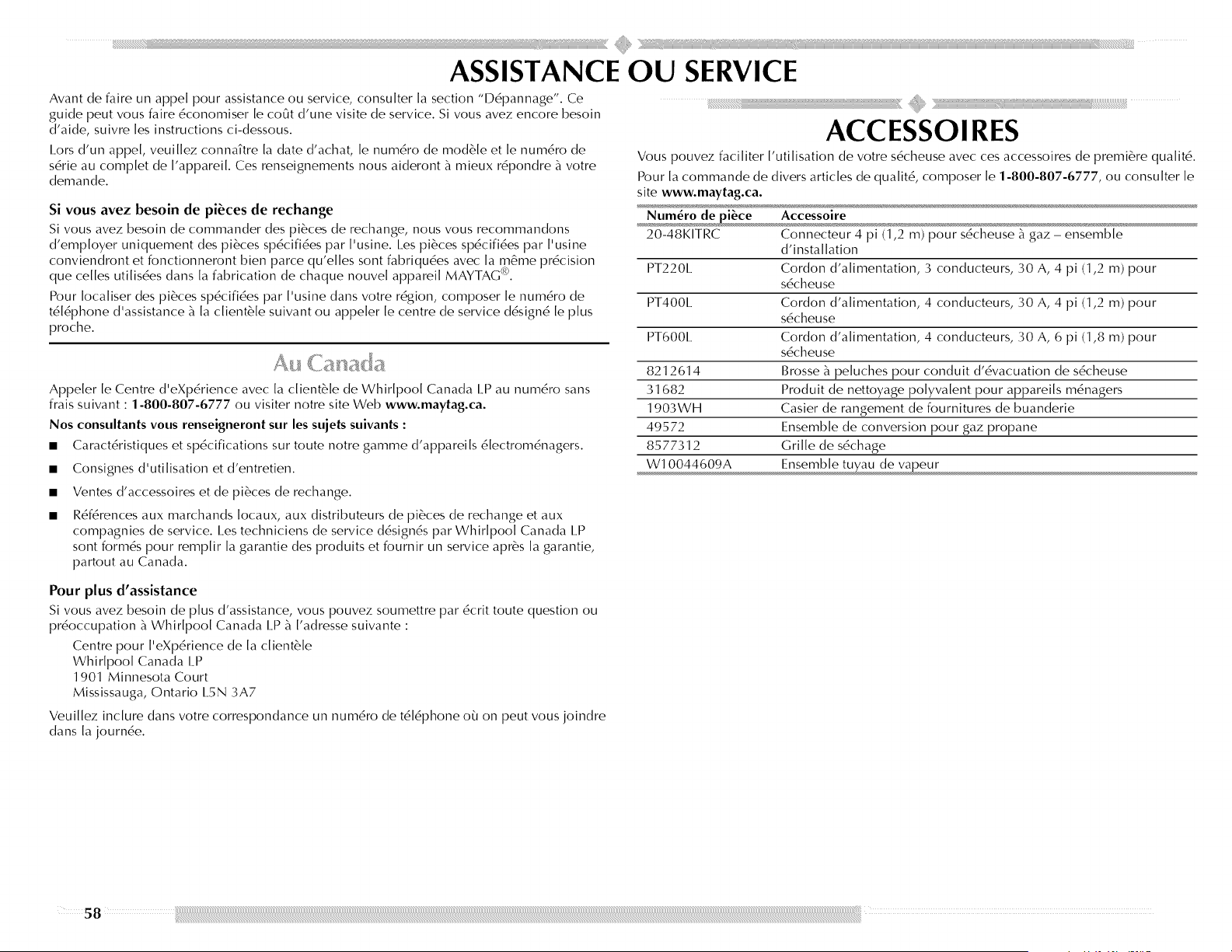
Avantdefaireunappelpourassistanceouservice,consulterlasection"l)6pannage".Ce
guidepeutvousfaire6conomiser [e co_t d'une visite de service. Si vous avez encore besoin
d'aide, suivre [es instructions ci-dessous.
I.ors d'un appe[, veui[[ez conna?tre [a date d'achat, [e num6ro de module et [e num6ro de
s6rie au comp[et de ['apparei[. Ces renseignements nous aideront _ mieux r6pondre _ votre
demande.
Si vous avez besoin de pi_ces de rechange
Si vous avez besoin de commander des pi_ces de rechange, nous vous recommandons
d'emp[oyer uniquement des pi_ces sp6cifi6es par ['usine. Les pi_ces sp6cifi6es par ['usine
conviendront et fonctionneront bien parce qu'e[[es sont fabriqu6es avec [a m_me pr6cision
que ce[[es uti[is6es dans [a fabrication de chaque nouve[ apparei[ MAYTAG <_.
Pour [oca[iser des pi_ces sp6cifi6es par ['usine dans votre r6gion, composer [e num6ro de
t6[6phone d'assistance _ [a c[ient_'[e suivant ou appe[er [e centre de service d6sign6 [e plus
proche.
Appeler le Centre d'eXpdrience avec la client_'le de Whirlpool Canada LP au numdro sans
frais suivant : 1-800-807-6777 ou visiter notre site Web www.maytag.ca.
Nos consultants vous renseigneront sur les sujets suivants :
• Caract6ristiques et sp6cifications sur route notre garnrne d'appareils 6lectrorn6nagers.
Consignes d'utilisation et d'entretien.
Ventes d'accessoires et de pi6ces de rechange.
R6f6rences aux marchands Iocaux, aux distributeurs de pi6ces de rechange et aux
compagnies de service. I.es techniciens de service d6sign6s par Whirlpool Canada I.P
sont form6s pour remplir la garantie des produits et fournir un service apr6s la garantie,
partout au Canada.
ACCESSOIRES
Vous pouvez faciliter I'utilisation de votre s6cheuse avec ces accessoires de premi6re qualit6.
Pour la commande de divers articles de qualit6, composer le 1-800-807-6777, ou consulter le
site www.maytag.ca.
Num_ro de _i_ce
20-48KITRC
PT2201 ....
PT4001 ....
PT6001 ....
8212614
31682
1903WH
49572
8577312
W10044609A
Accessoi re
Connecteur 4 pi (1,2 rn) pour s6cheuse _ gaz - ensernble
d'insta[[ation
Cordon d'a[imentation, 3 conducteurs, 30 A, 4 pi (1,2 m) pour
s6cheuse
Cordon d'a[imentation, 4 conducteurs, 30 A, 4 pi (1,2 m) pour
s6cheuse
Cordon d'a[imentation, 4 conducteurs, 30 A, 6 pi (1,8 m) pour
s6cheuse
Brosse _ pe[uches pour conduit d'6vacuation de s6cheuse
Produit de nettoyage polyvalent pour appareils m6nagers
Casier de rangement de fournitures de buanderie
Ensemble de conversion pour gaz propane
Grille de s6chage
Ensemble tuyau de va_eur
Pour plus d'assistance
Si vous avez besoin de plus d'assistance, vous pouvez sournettre par 6crit route question ou
pr6occupation _ Whirlpool Canada I.P _ ['adresse suivante :
Centre pour ['eXp6rience de [a c[ient_'[e
Whirlpool Canada I_P
1901 Minnesota Court
Mississauga, Ontario 1.5N 3A7
Veuillez inclure dans votre correspondance un num6ro de t616phone o_ on peut vous joindre
dans la journ6e.
58

GARANTIE DES GROS APPAREILS MENAGERS MAYTAG
GARANTIE LIMITI_E
Pendant un an _ cornpter de la date d'achat, Iorsque ce gros appareil rn6nager est utilis6 et entretenu conforrn6rnent aux instructions jointes _ ou fournies avec le produit, la marque Maytag de
Whir[pool Corporation ou Whir[pool Canada I_P (ci-apr6s d6sign6es "Maytag") paiera pour [es pi6ces sp6cifi6es par ['usine et [a main-d'oeuwe pour corriger [es vices de mat6riaux ou de
fabrication. I.e service doit 6tre fourni par une compasnie de service d6sign6e par Maytag. Cette garantie [imit6e est va[ide uniquement aux Etats-Unis ou au Canada et s'app[ique exc[usivement
[orsque ['apparei[ est uti[is6 dans [e pays o_ i[ a 6t6 achet6. A ['ext6rieur du Canada et des 50 Etats des Etats-Unis, cette garantie [imit6e ne s'app[ique pas. Une preuve de [a date d'achat original
est exig6e pour obtenir un service dans [e cadre de [a pr6sente garantie [imit6e.
ARTICLES EXCLUS DE LA GARANTIE
La pr_sente garantie limit_e ne couvre pas :
1. I.es visites de service pour rectifier ['installation du gros apparei[ rn6nageb rnontrer _ ['uti[isateur comment uti[iser ['apparei[, rernp[acer ou r6parer des fusib[es ou rectifier [e cib[age ou [a
p[omberie du domicile.
2. I.es visites de service pour r6parer ou remp[acer [es ampou[es 6[ectriques de ['apparei[, [es fi[tres _ air ou [es fi[tres _ eau. I.es pi6ces consomptib[es ne sont pas couvertes par [a garantie.
3. I.es r6parations [orsque [e gros apparei[ m6nager est uti[is6 _ des fins autres que ['usage unifami[ia[ normal ou [orsque [es instructions d'insta[[ation et/ou [es instructions de ['op6rateur ou de
['uti[isateur fournies ne sont pas respect6es.
4. I.es dommages imputab[es _ : accident, modification, usage impropre ou abusif, incendie, inondation, actes de Dieu, installation fautive ou installation non conforme aux codes
d'6[ectricit6 ou de p[omberie, ou ['uti[isation de pi6ces consomptib[es ou de produits nettoyants non approuv6s par Maytag.
5. I_es d6fauts apparents, notamment [es 6raf[ures, [es bosses, fissures ou tout autre dommage au fini du gros apparei[ m6nager, _ moins que ces dommages soient dus _ des vices de mat6riaux
ou de fabrication et soient signa[6s _ Maytag dans [es 30 jours suivant [a date d'achat.
6. Toute perte d'a[iments due _ une d6fai[[ance du r6frig6rateur ou du cong6[ateur.
7. I_es coots associ6s au transport du gros apparei[ m6nager du domicile pour r6paration. Ce gros apparei[ m6nager est congu pour 6tre r6par6 _ domicile et seu[ [e service _ domicile est
couvert par [a pr6sente garantie.
8. I.es r6parations aux pi6ces ou syst6mes r6su[tant d'une modification non autoris6e faite _ ['apparei[.
9. I_es frais de transport pour [e service d'un produit si votre gros apparei[ est situ6 dans une r6gion 6[oign6e o_ un service d'entretien Maytag autoris6 n'est pas disponib[e.
10. I.a d6pose et [a r6insta[[ation de votre gros apparei[ si ce[ui-ci est install6 dans un endroit inaccessible ou n'est pas install6 conform6ment aux instructions d'insta[[ation fournies.
11. I.es gros apparei[s m6nagers dont [es num6ros de s6rie et de mod6[e originaux ont 6t6 en[ev6s, modifi6s ou qui ne peuvent pas 6tre faci[ement identifi6s. I.a pr6sente garantie est nu[[e si [e
num6ro de s6rie d'usine a 6t6 modifi6 ou en[ev6 du gros apparei[ m6nager.
I.e coot d'une r6paration ou des pi6ces de rechange dans [e cadre de ces circonstances exc[ues est _ [a charge du c[ient.
CLAUSE D_EXONI_RATION DE RESPONSABILITI_ AU TITRE DES GARANTIES IMPLICITES; LIMITATION DES RECOURS
I_ESEUI_ ET EXCI.USIF RECOURS DU CLIENT DANS I.E CADRE DE I.A PRESENTE GARANTIE I.IMITEE CONSISTE EN I_A REPARATION PREVUE CI-DESSUS. I_ES GARANTIES IMPI_ICITES, Y
COMPRIS LES GARANTIES APPI_ICABI_ES DE QUALITE MARCHANDE ET D'APTITUDE A UN USAGE PARTICUI_IER, SONT LIMITEES A UN AN OU A I_A PLUS COURTE PERIODE
AUTORISEE PAR LA I_OI. MAYTAG N'ASSUME AUCUNE RESPONSABII_ITE POUR I_ES DOMMAGES FORTUITS OU INDIRECTS. CERTAINES JURIDICTIONS NE PERMETTENT PAS
I_'EXCI.USION,OU LA LIMITATION DES DOMMAGES FORTUITS OU INDIRECTS, OU I_ESI_IMITATIONS DE LA DUREE DES GARANTIES IMPI_ICITES DE QUALITE MARCHANDE OU.
D'APTITUDE A UN USAGE PARTICUI_IER, DE SORTE QUE CES EXCLUSIONS OU I_IMITATIONS PEUVENT NE PAS S'APPLIQUER DANS VOTRE CAS. CETTE GARANTIE VOUS CONFERE
DES DROITS JURIDIQUES SPECIFIQUES ET VOUS POUVEZ EGAI.EMENT JOUIR D'AUTRES DROITS QUI PEUVENT VARIER D'UNE JURIDICTION A UNE AUTRE.
Si vous r6sidez _ ['ext6rieur du Canada et des 50 @ats des @ats-Unis, contactez votre marchand Maytag autoris6 pour d6terminer si une autre garantie s'app[ique.
Si vous avez besoin de service, voir d'abord [a section "D6pannage" du Guide d'uti[isation et d'entretien. Apr6s avoir v6rifi6 [a section "D6pannage", de ['aide supp[6mentaire peut 6tre trouv6e
en v6rifiant [a section "Assistance ou service" ou en appe[ant Maytag. Aux E.-U., composer [e 1-800-688-9900. Au Canada, composer [e 1-800-807-6777. 1/08
Conservez ce manuel et votre re<;u de vente ensemble pour r_f_rence ult_rieure.
Pour le service sous garantie, vous devez presenter un document prouvant la date
d'achat ou d'installation.
Inscrivez les renseignements suivants au sujet de votre gros appareil menager pour mieux
vous aider a obtenir assistance ou service en cas de besoin. Vous devrez connaftre le
numero de modele et le numero de serie au complet. Vous trouverez ces renseignements
sur la plaque signaletique situee sur le produit.
Nom du marchand
Adresse
Num_ro de t_l_phone
Num_ro de module
Num_ro de s_rie
Date d'achat

W10201177A
<020<)8
All rights reserved.
lbus droits r6serv6s.
®Registered trademarl</v'_ Trademarl< of Maytag Corporation or its related companies.
Used under license by Maytag [imited in Canada
0<)Marque d6pos6e/_'_Marque de commerce de Maytag Corporation ou de ses compagnies affili6es.
Emploi sous licence par Maytag Iimited au Canada.
6/08
Printed in U,S.A.
Imprinr6 aux E,-U.