For customer support, please contact:
US Patent 8317470, 8807938, 8790085, 9255584, 8851841
V1.0 (12/2019)
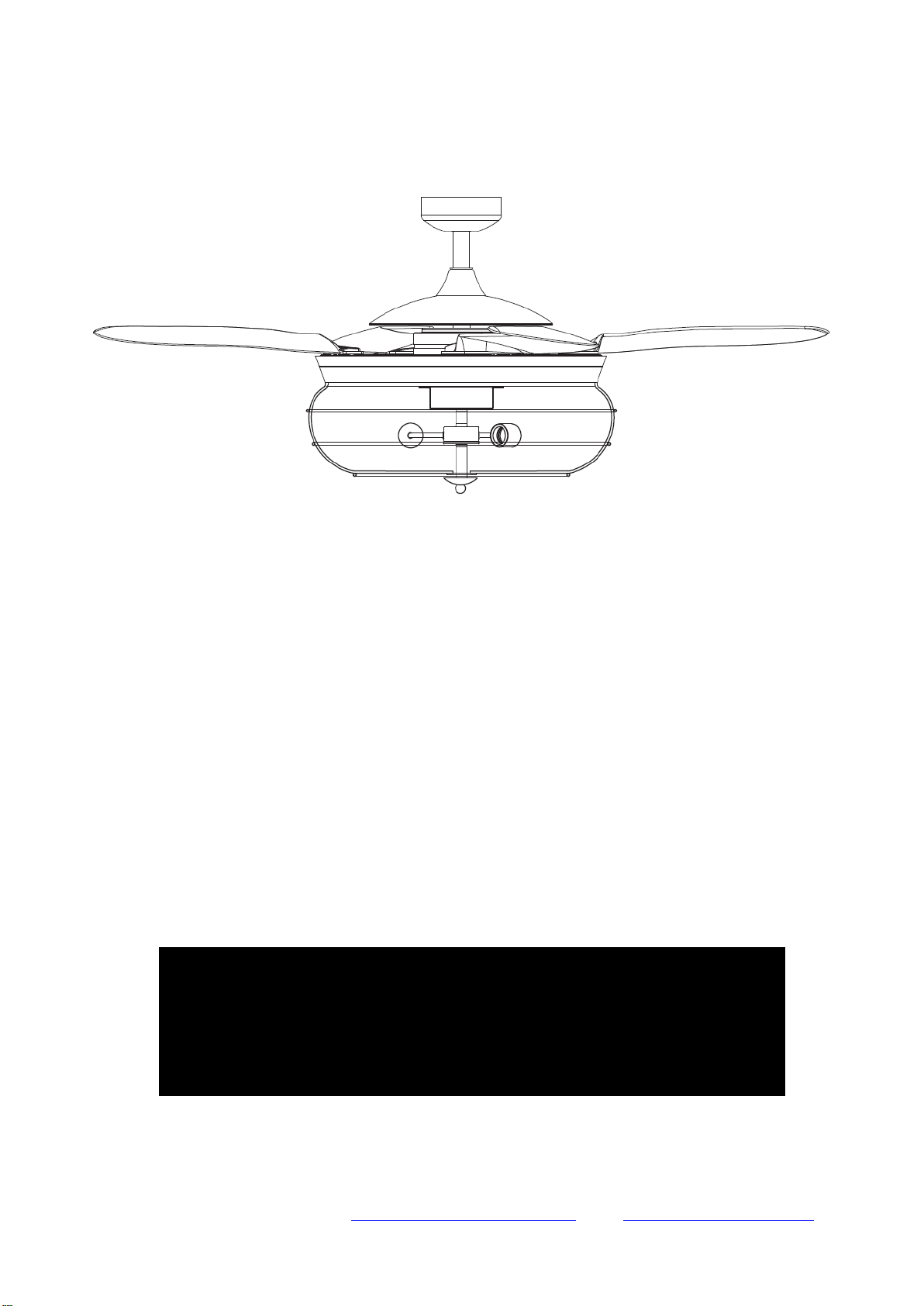
FANAWAY ALISTAIR
CEILING FAN
INSTALLATION
OPERATION
MAINTENANCE
WARRANTY INFORMATION
CAUTION
READ INSTRUCTIONS CAREFULLY FOR SAFE
INSTALLATION AND FAN OPERATION.

Fanaway Alistair Installation Instructions
2 | P age
A L I S T A I R - M E N A R D S V e r s i o n 1 . 0 1 2 / 2 0 1 9
THANK YOU FOR PURCHASING
Thank you for purchasing this quality Fanaway product. To ensure correct function and safety, please
read and follow all instructions before assembly, installation and use of this ceiling fan. Please keep
instructions for future reference.
SAFETY PRECAUTIONS
Read and Save These Instructions
This product conforms to UL standard 507.
1. WARNING -To avoid possible electrical shock, before installing or servicing your fan, disconnect the
power by turning off the circuit breaker of the fuse box to the outlet box.
2. WARNING - To reduce the risk of fire, electric shock, or personal injury, mount to outlet box marked
“acceptable for fan support of 70 lbs (31.8 kg) or more” and use the mounting screws provided with
the outlet box and/or support directly from building structure. Most outlet boxes commonly used for
the support of luminares may not be acceptable for fan support and may need to be replaced.
Consult a qualified electrician if in doubt.
3. WARNING - To reduce the risk of fire or electric shock, do not use this fan with any solid-state speed
control device.
4. WARNING - To reduce the risk of personal injury, do not bend the blade brackets when installing the
blade brackets balancing the blades, or cleaning the fan. Do not insert foreign objects in between
rotating fan blades.
5. CAUTIONS - All wiring must be in accordance with the National Electrical Code (ANSI/NFPA 70)
and local electrical codes. Electrical installation should be performed by a qualified licensed
electrician.
6. To reduce the risk of injury to person, the fan must be mounted with a minimum of 7 feet clearance
from the bottom edge of the blades to the floor.
7. After marking electrical connections, spliced conductors should be turned upward and pushed
carefully up into the outlet box. The wires should be spread apart with the grounded conductor and
the equipment-grounding conductor on one side of the outlet box.
8. This equipment has been tested and found to comply with the limits for a Class B digital device,
pursuant to part 15 of the FCC rules. These limits are to provide reasonable protection against
harmful interference in a residential installation. This equipment generates, uses and can radiate
radio frequency energy and if not installed and used in accordance with the instructions may cause
harmful interference to radio communications.
Fanaway Alistair Installation Instructions
3 | P age
A L I S T A I R - M E N A R D S V e r s i o n 1 . 0 1 2 / 2 0 1 9
PARTS LIST
Unpack your ceiling fan and carefully. Remove all parts and hardware.
Lay out all the components on a smooth surface and make sure there are no components missing
before assembling. If parts are missing, return the complete product to the place of purchase for
inspection or replacement.
Check whether the ceiling fan has been damaged during transport. Do not operate/install any
product which appears damaged in any way. Return the complete product to the place of purchase
for inspection, repair or replacement.
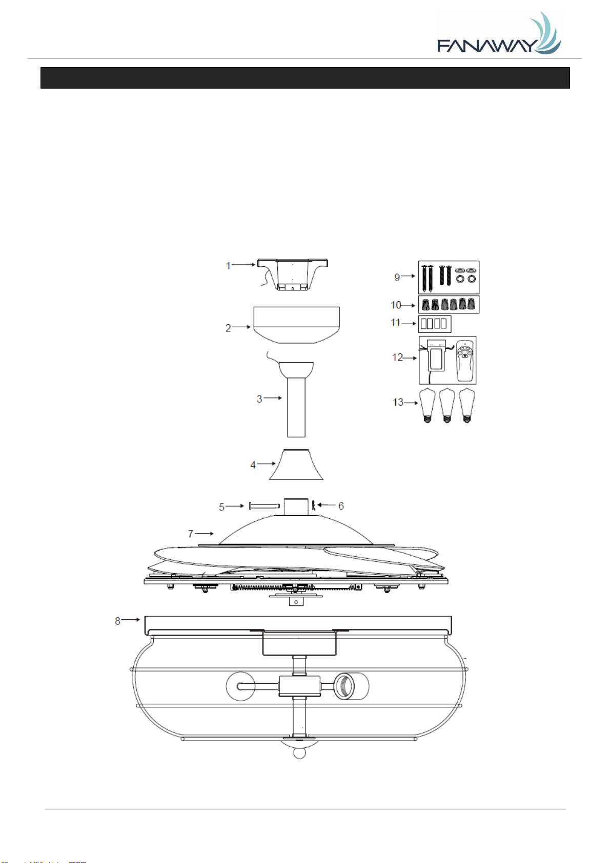
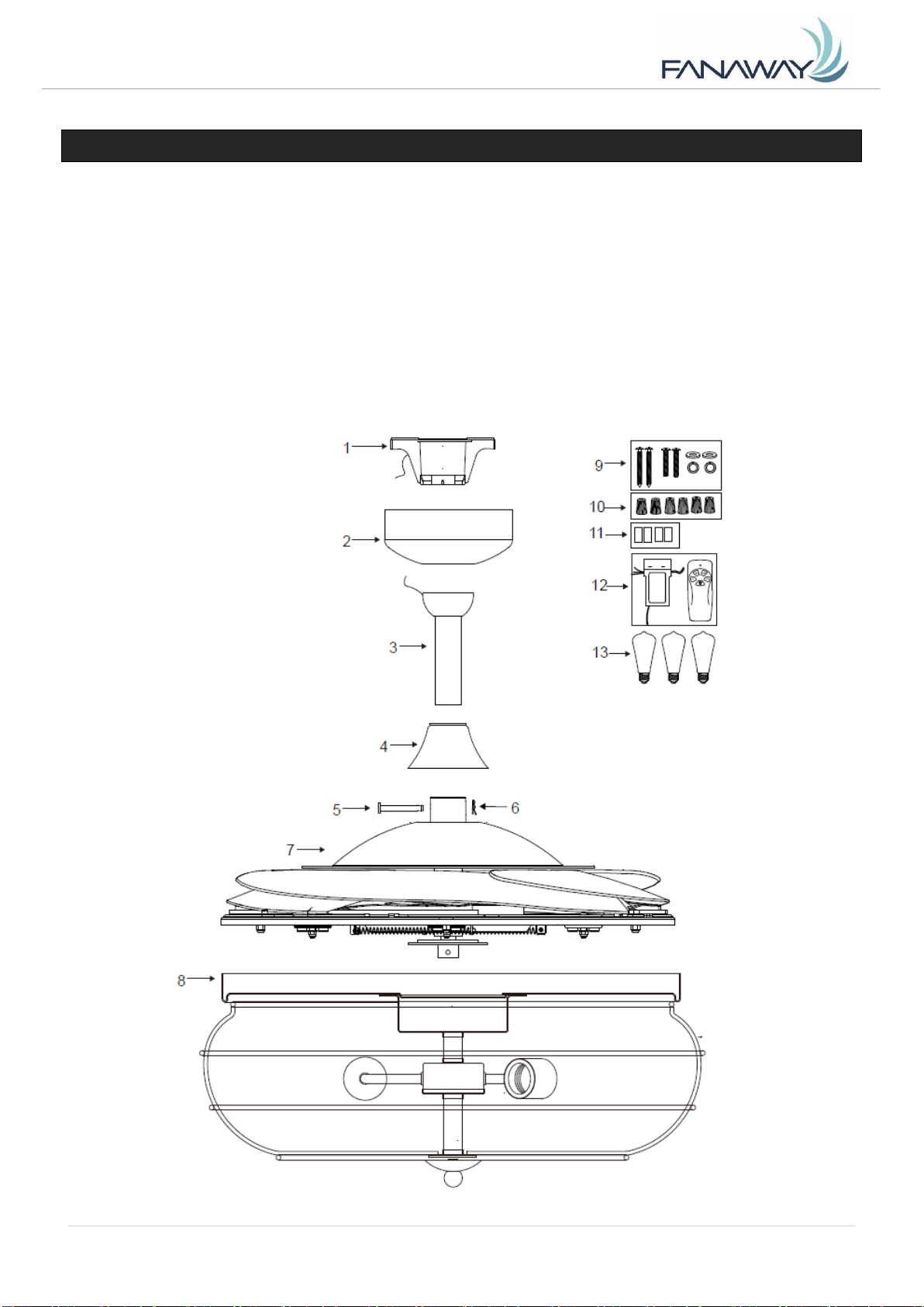
Examine and identify the parts. Please refer to Fig 1.
Fig. 1
Fanaway Alistair Installation Instructions
4 | P age
A L I S T A I R - M E N A R D S V e r s i o n 1 . 0 1 2 / 2 0 1 9
1
Mounting bracket x 1
9
Wood screw x 2
2
Canopy x 1
Machine screw x 2
3
Down rod with ball joint x 1
Flat washer x 2
4
Bolt and pin cover x 1
Spring washer x 2
5
Bolt x 1
10
Wire nut x 6
6
Pin x 1
13
Balance tape x 4
7
Fan assembly x 1
14
Receiver & Remote x 1 Set
8
Lamp base and shade x 1
15
LED bulb x 3
INSTALLING THE MOUNTING BRACKET
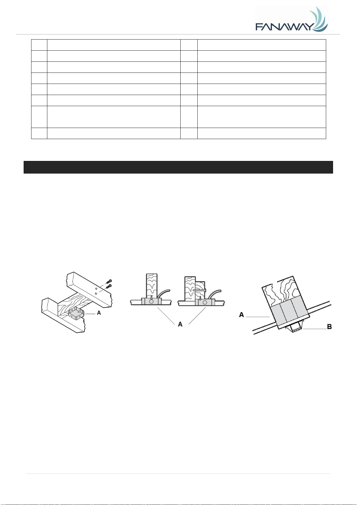
If there isn’t an existing outlet box, then install one using the following instructions:
Disconnect the power by removing the fuses or turning off the circuit breakers.
Secure the outlet box (A) (not included) directly to the building structure. Use appropriate fasteners
and materials (not included). The outlet box and its bracing must be able to fully support the weight
of the moving fan (at least 70 lbs). Do not use a plastic outlet box.
Figures below show three different ways to mount the outlet box (A) (not included).
This fan hanging system supports a maximum 15 degree angled ceiling installation. Fig. 4
NOTE: If you are installing the ceiling fan on a sloped ceiling, you may need a longer downrod to
maintain proper clearance between the tip of the blade and the ceiling.
NOTE: The ceiling fan must be installed in a location so that the blades are spaced 300mm from the tip
of the blade to the nearest objects or walls.
NOTE: For angled ceiling installation, the opening of the mounting bracket (B) must be pointed toward
the peak.
Fig. 2
Fig. 3
Fig. 4
Angled ceiling
Maximum 15°
Fanaway Alistair Installation Instructions
5 | P age
A L I S T A I R - M E N A R D S V e r s i o n 1 . 0 1 2 / 2 0 1 9
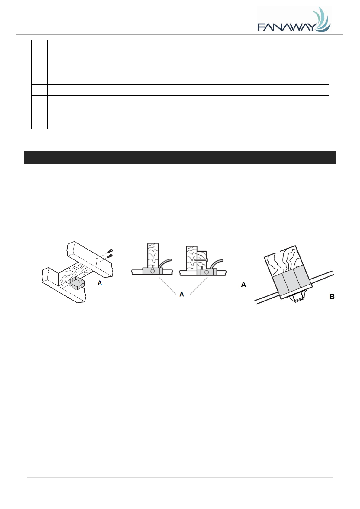
To hang your fan where there is an existing fixture but no ceiling joist, you may need an installation
hanger bar (C) as shown in Fig.5. Make sure the hanger bar you purchase has been designed for use
with ceiling fans.
INSTALLING THE FAN
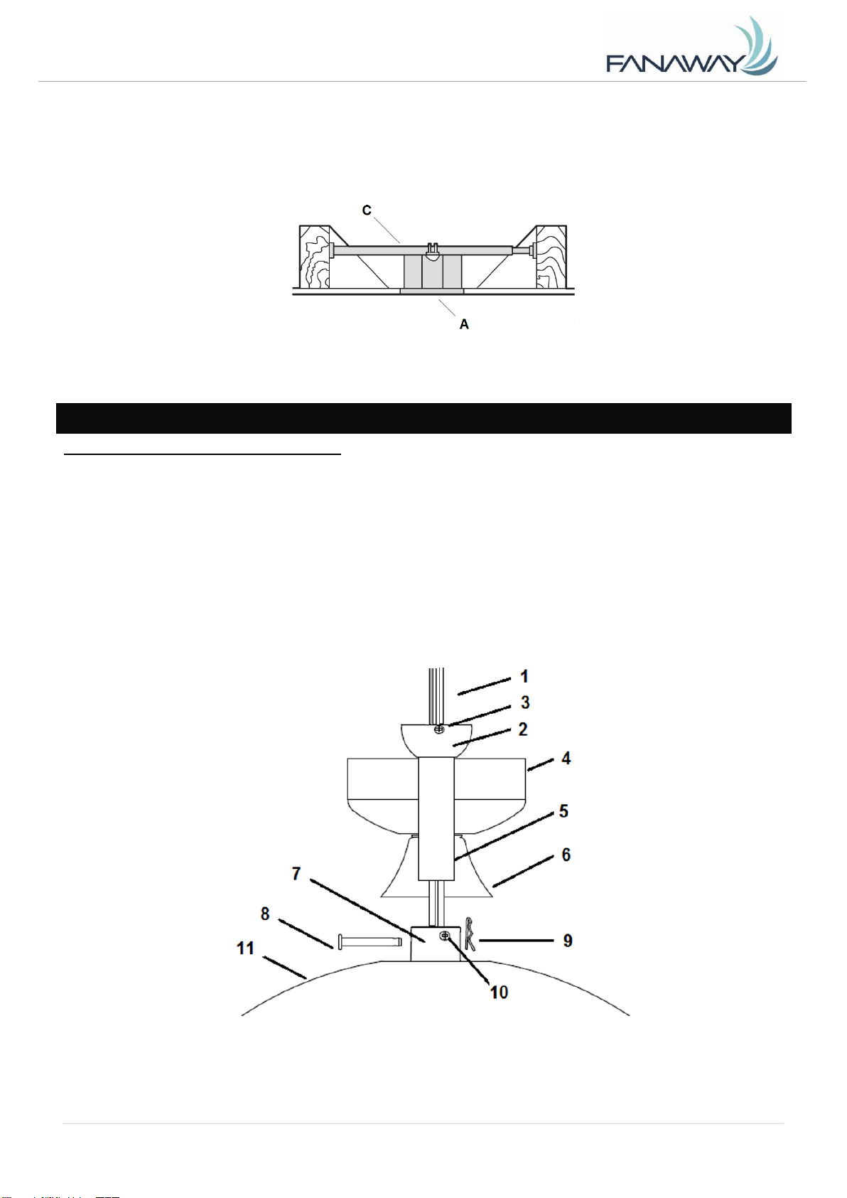
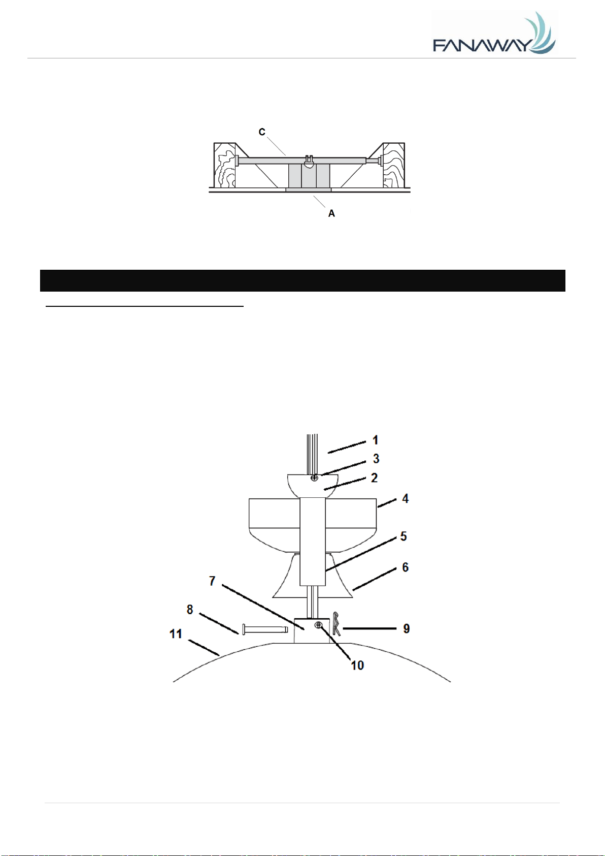
INSTALLING THE DOWN ROD (Fig. 6)
1. Feed the down rod (5) through the canopy (4) and the bolt and pin cover (6).
2. Remove the ball joint (2) by loosening the set screw (3), insert the motor wires through the down rod
then secure the ball joint back to the down rod.
3. Insert the down rod to the coupling (7), line up the coupling holes with the down rod holes and insert
the bolt (8). Then insert the pin (9) to the end of the bolt.
4. Finally secure the down rod and coupling by tightening the two set screws (10) on the coupling. Fig. 6
Fig. 6
Fig. 5
Fanaway Alistair Installation Instructions
6 | P age
A L I S T A I R - M E N A R D S V e r s i o n 1 . 0 1 2 / 2 0 1 9
FAN INSTALLATION
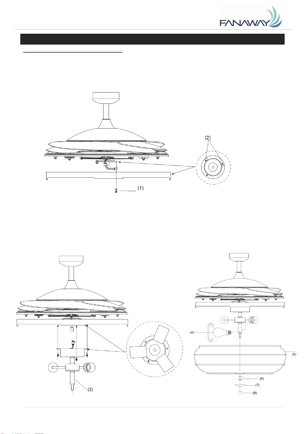
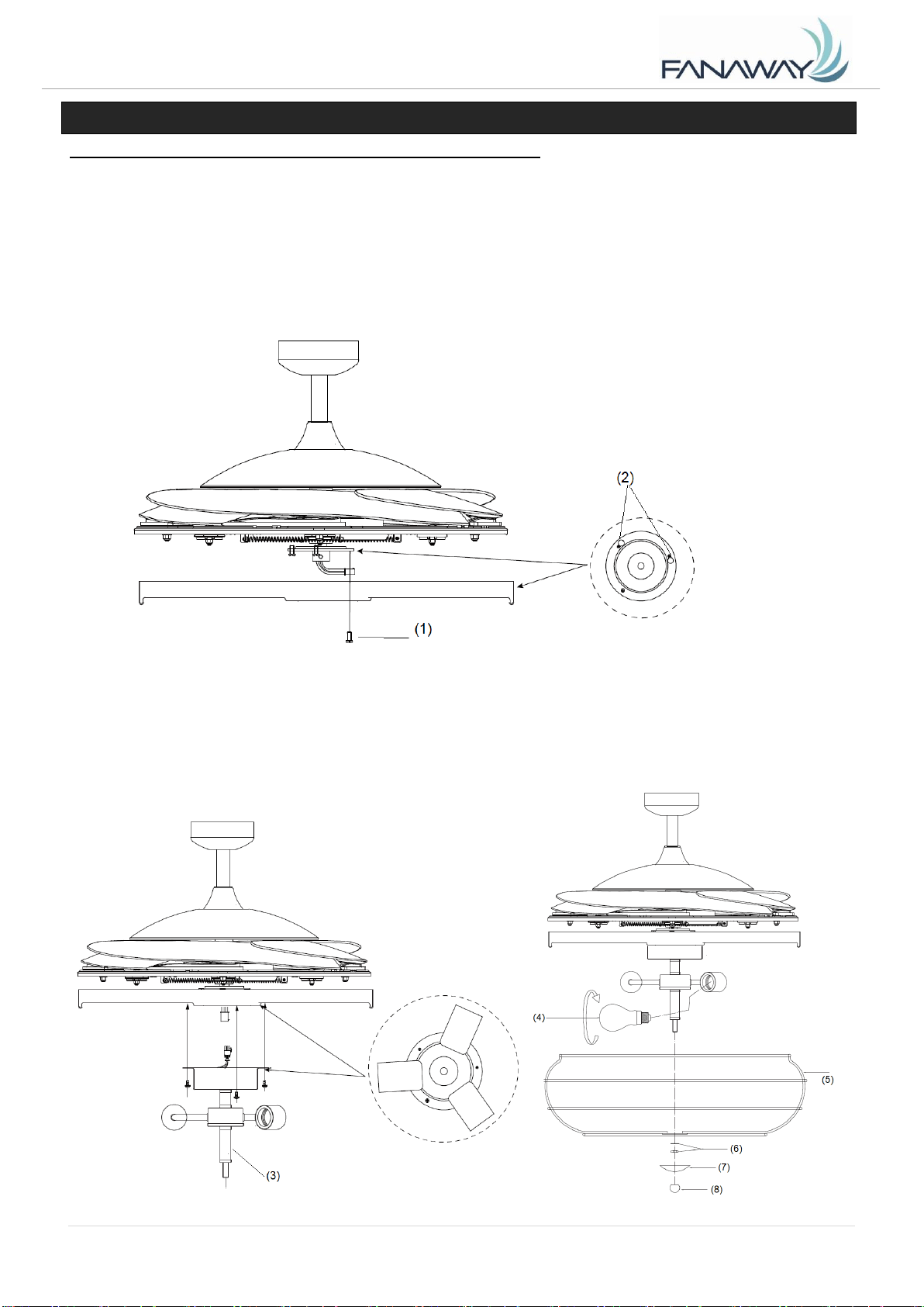
LIGHT KIT INSTALLATION (Fig.7 & 8)
1. Loosen the screw (1) from the fan bracket. Align the two slot screws with the keyhole slots (2) of the
light kit bracket. (Fig. 7)
2. Turn the light kit counterclockwise until the slot screws are firmly at the end of the slots (2).
3. Secure screw (1) to the lamp shade bracket. Tighten all three screws. Do not over-tighten.
4. Connect the quick connector to the lamp holder part (3). (Fig. 8)
5. Secure the lamp-holder part (3) to the light kit bracket by tightening the 3 screws. Do not
over-tighten.
6. Install the globes (4) to the lamp holders. Do not exceed the maximum power rating.
7. Install the lamp shade followed by the washer and the nut (6). Tighten the nut (6).
8. Install the decorative cover (7) by tightening the nut (8).
Fig. 7
Fig. 8
Fanaway Alistair Installation Instructions
7 | P age
A L I S T A I R - M E N A R D S V e r s i o n 1 . 0 1 2 / 2 0 1 9
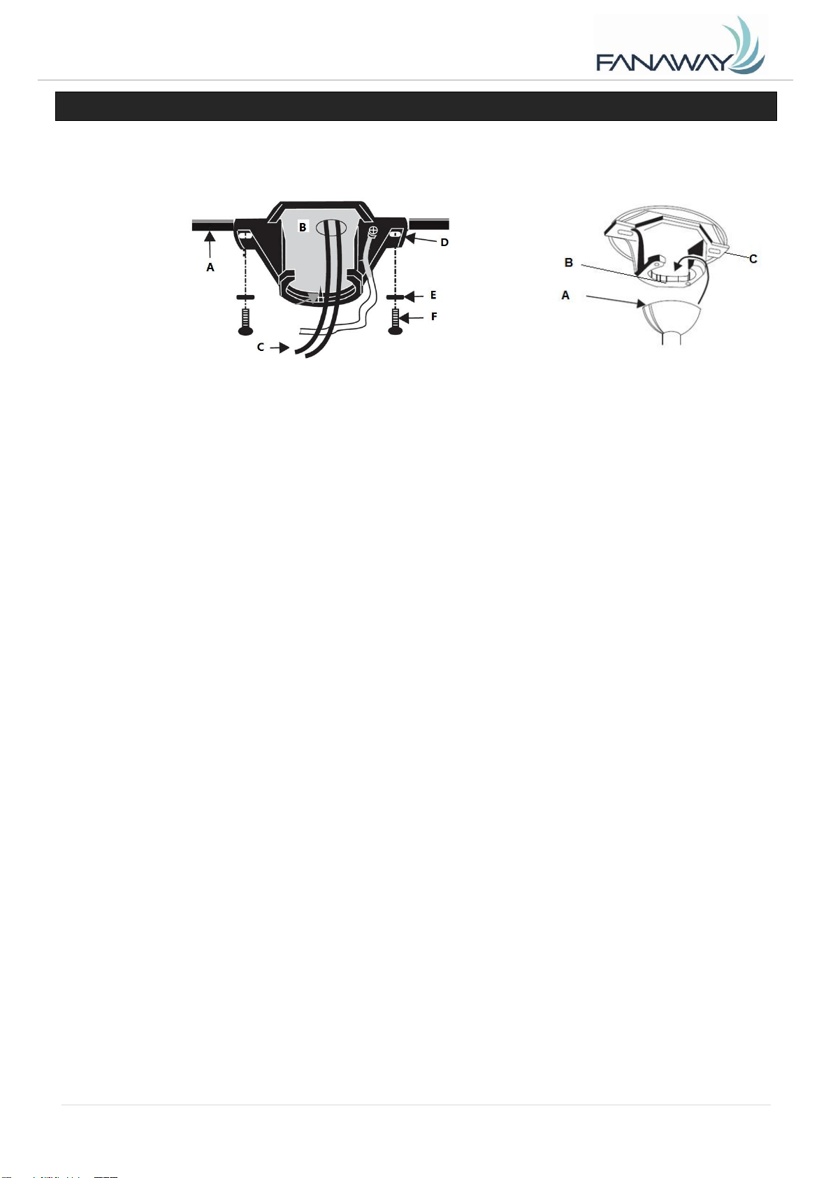
HANGING THE FAN
Pass the power supply wires (C) from the ceiling outlet box (B) through the center of the ceiling mounting
bracket (D). Install the ceiling mounting bracket (D) on the outlet box (B) with the mounting screws (F)
provided with the outlet box and washers (E) provided with fan. Fig. 9
Lift the fan assembly onto the mounting bracket. Ensure the key slot (A) of the hanger ball is positioned
on the key pin (B) of the mounting bracket (C) to prevent the fan from rotating when in operation. Fig.10
Fig. 9
Fig. 10
Fanaway Alistair Installation Instructions
8 | P age
A L I S T A I R - M E N A R D S V e r s i o n 1 . 0 1 2 / 2 0 1 9
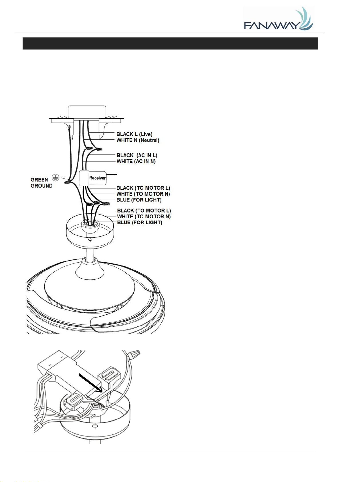
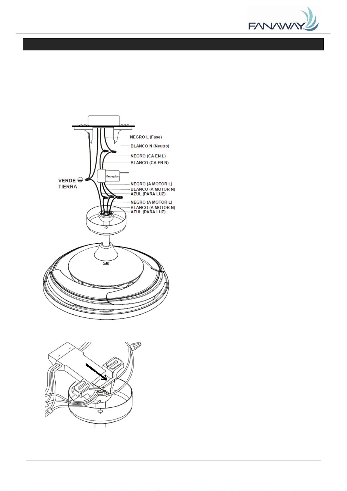
ELECTRICAL WIRING DIAGRAM
WARNING: To avoid possible electrical shock, be sure you have turned off the power at the main circuit
panel.
Follow the steps below to connect the fan to your household wiring. Use the wire connecting nuts
supplied with your fan. Secure the connectors with electrical tape. Make sure there are no loose wire
strands or connections.
1. Connect the household live supply wire
(black) to receiver input wire (black, AC IN L) as
shown in Fig. 11.
2. Connect the household neutral supply
wire (white) to the receiver input wire (white, AC
IN N).
3. Connect the household ground wire to
the fan bracket ground wire (green) and fan body
ground wire.
4. Connect the reveiver output wire (black,
TO MOTOR L) to motor live input wire (black, TO
MOTOR L).
5. Connect the receiver output wire (white,
TO MOTOR N) to motor neutral input wire (white,
TO MOTOR N)
6. Connect the receiver output wire (blue,
FOR LIGHT) to fan light live input wire (blue,
FOR LIGHT)
7. After connecting the wires, spread
them apart so that the green and white wires are
on one side of the outlet box and the black and
blue wires are on the other side.
8. Turn the connecting nuts upward and
push the wiring into the outlet box.
Fig. 11
9. Carefully insert the Remote Receiver above
the hanger ball in the remainder spacing in the
mounting bracket. Take care not to damage or
loosen any of the wiring.
Fanaway Alistair Installation Instructions
9 | P age
A L I S T A I R - M E N A R D S V e r s i o n 1 . 0 1 2 / 2 0 1 9
FINISHING THE INSTALLATION
Slide and align the canopy up to the mounting bracket. Ensure all electrical wiring is tucked inside the
canopy and that the wires are not damaged during this step. Secure the canopy to the hanger bracket
using the screws provided.
USING YOUR CEILING FAN
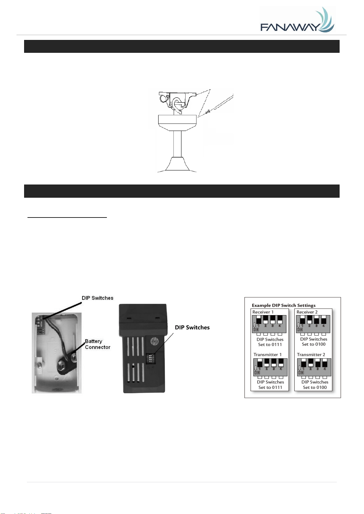
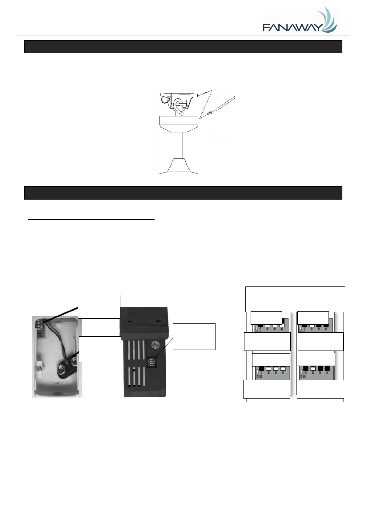
SETTING DIP SWITCHES
When two or more fans are located near each other, you may desire to have the receiver/transmitter for
each fan set to a different code, so that the operation of one fan does not affect the operation of the other
fans.
The DIP switches for the receiver are located on the flat surface of the receiver. The DIP switches for the
transmitter are in the battery compartment. Fig. 13.
NOTE: Ensure that the power to the supply wires has been turned off before setting the code.
Change the position of the DIP switches in the remote transmitter and the receiver. Make sure that the
DIP switches match in the remote receiver and transmitter. If they don’t match, the transmitter will not
function. Fig. 14
Fig. 12
Fig. 14
Fig. 13
Fanaway Alistair Installation Instructions
10 | P age
A L I S T A I R - M E N A R D S V e r s i o n 1 . 0 1 2 / 2 0 1 9
INSTALLING THE REMOTE BATTERY
1 x 9V DC (size) battery is required to operate the remote control. Remove the battery cover from the
back of the remote and 1 x 9V DC (size) battery. Ensure the polarities are correct as shown on the
battery connector. (Batteries included.)
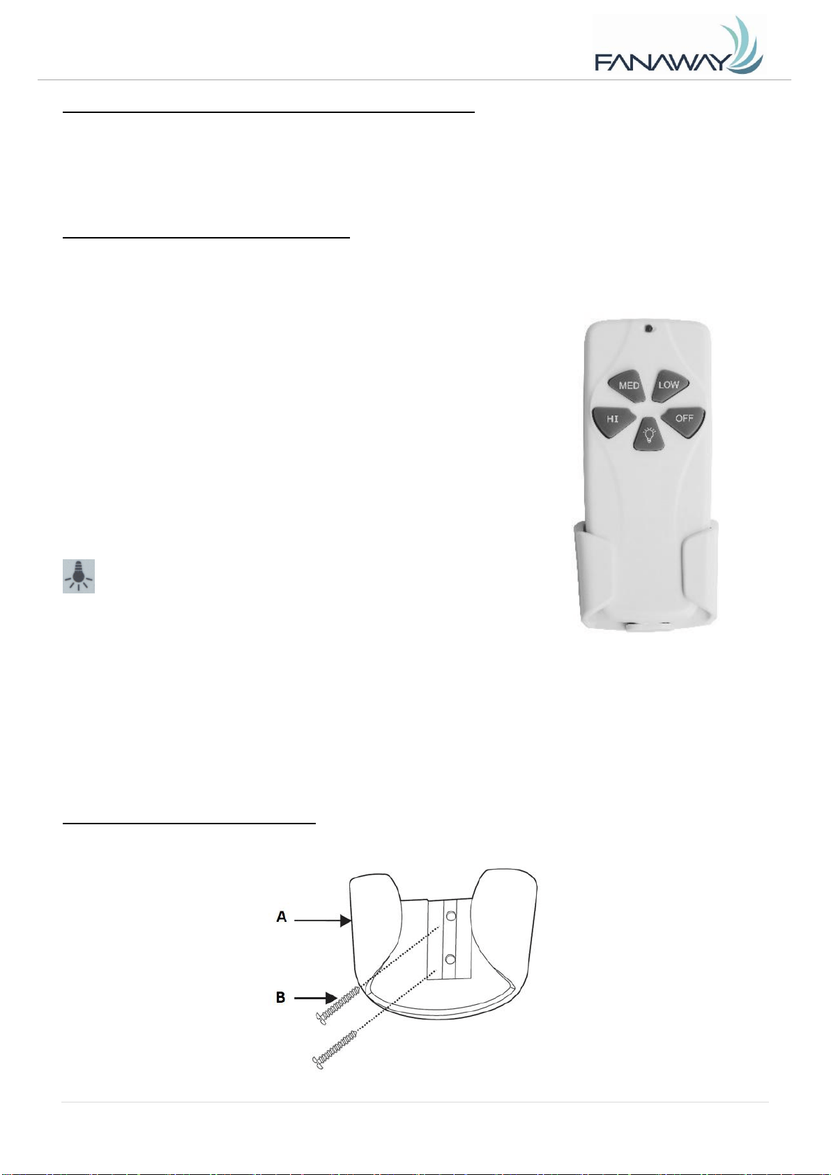
OPERATING THE REMOTE:
Before you start using the remote, take the time to read through this section and get familiar with the
buttons and function of each button.
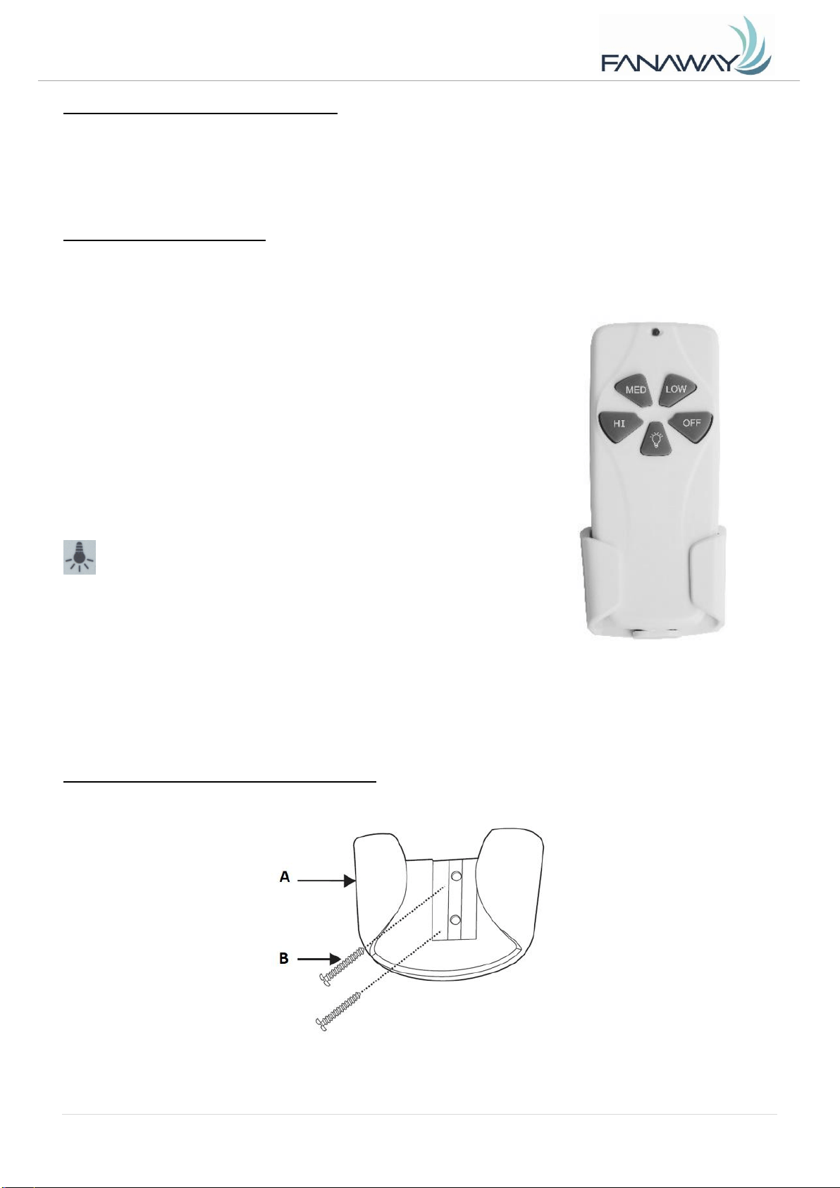
LED Indicator
The red LED indicator on the top of the transmitter will flash when the
buttons are active.
BUTTONS ON THE REMOTE
HI: Press the button to set fan running at High speed.
MED: Press the button to set fan running at Medium speed.
LOW: Press the button to set fan running at Low speed.
OFF: Press the button to turn OFF the fan.
LIGHT CONTROL BUTTON:
Press the button to turn the light ON/OFF.
Press and hold the button to access the light dimming function.
The remote has memory function. If the fan or light is turned off by the isolating switch, it will memorise
and recover the last status when turned on next.
INSTALLING THE TRANSMITTER HOLDER
Install the holder to the wall with two screws provided, hang up the transmitter by the holder.
Fig. 16
Fig. 15
Fanaway Alistair Installation Instructions
11 | P age
A L I S T A I R - M E N A R D S V e r s i o n 1 . 0 1 2 / 2 0 1 9
AFTER INSTALLATION
WOBBLE:
NOTE: ceiling fans tend to move during operation due to the fact that they are mounted on a rubber
grommet. If the fan was mounted rigidly to the ceiling it would cause excessive vibration. Movement of a
few centimetres is quite acceptable and DOES NOT suggest any problem.
TO REDUCE THE FAN WOBBLE: Please check that all screws which fix the mounting bracket and
down rod are secure.
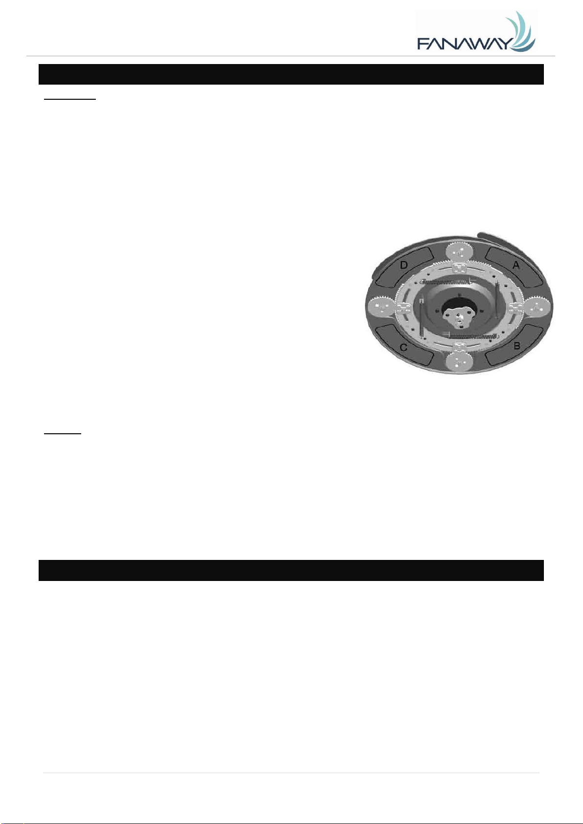
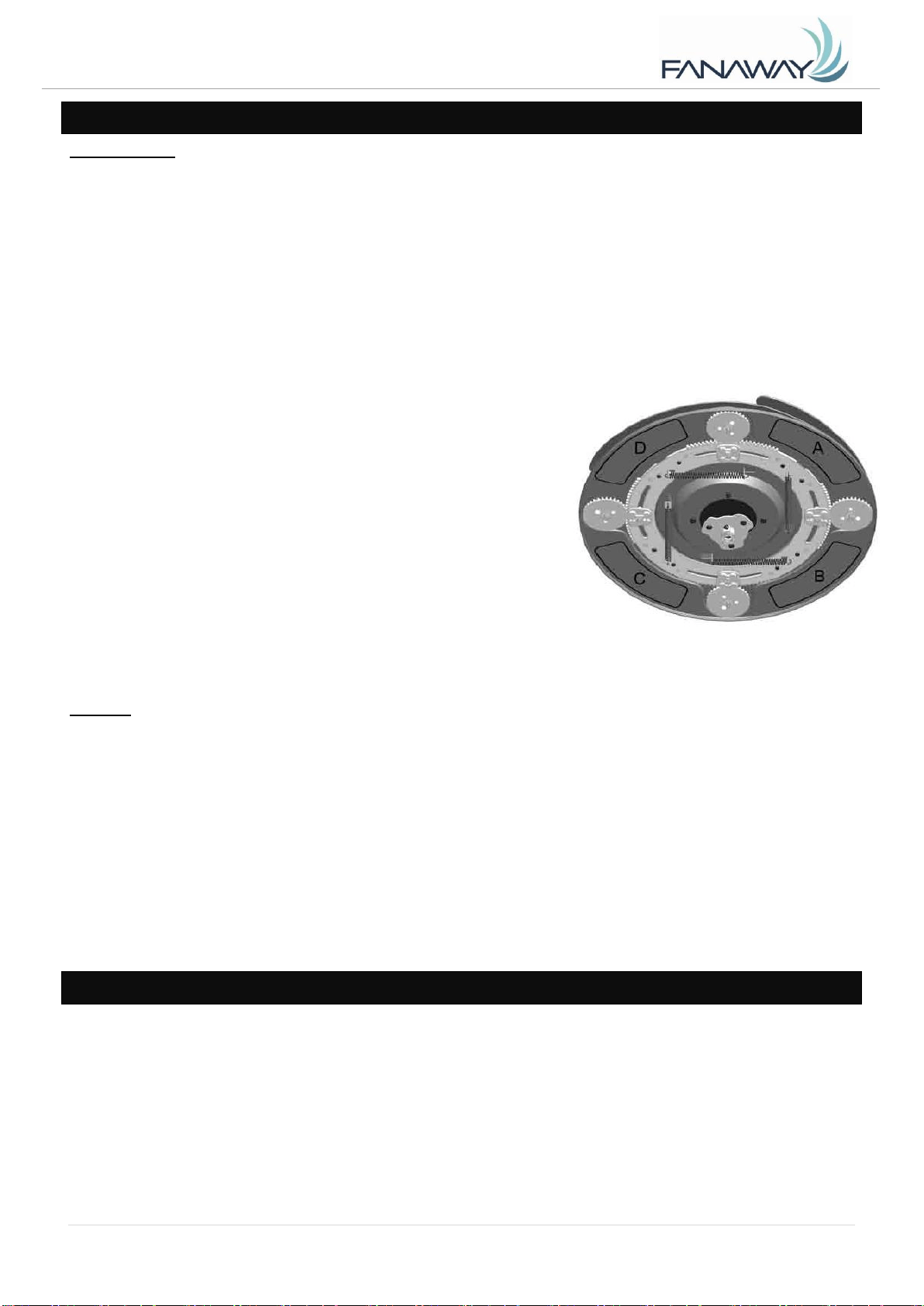
BALANCING A WOBBLING CEILING FAN:
For your convenience, a Balancing Kit is included; please follow this procedure when balancing the fan:
1) Install the fan without the light kit before balancing the fan.
2) Define the base plate into four areas (point A, B, C and D).
Use one weight from the balance kit to lightly stick on the
edge of the base plate (point A), if the wobble worsens, then
take off the balance kit and lightly stick it on the opposite side
(point C); if the wobble is worse, then go to the adjacent point
B or D, if the wobble gets lessens, then securely stick on the
weight at this location on the base plate.
3) After balancing the fan, assemble the light kit to the light
base.
NOISE:
When it is quiet (especially at night) you may hear occasional small noises. Slight power fluctuations and
frequency signals superimposed in the electricity for off-peak hot water control, may cause a change in
fan motor noise. This is normal. Please allow a 24-hour “breaking -in” period, most noises associated
with a new fan disappear during this time. All electric motors are audible to some extent. Please note that
this is not a product fault, and as such is not covered under warranty.
CARE & CLEANING
NOTE: Always turn OFF the power at the mains switch before performing any maintenance or
attempting to clean your fan.
1) Every 6 months periodic cleaning of your ceiling fan is the only maintenance required. Use a soft
brush or lint free cloth to avoid scratching the paint finish. Please turn OFF electricity power when
you do so.
2) Do not soak or immerse your ceiling fan in water or other liquids. It could damage the motor or the
blades and create the possibility of an electrical shock.
3) Ensure that the fan does not come in contact with any organic solvents or cleaners.
4) To clean the fan blade, wipe with only a damp clean cloth with NO organic solvents or cleaners.
5) The motor has a permanently lubricated ball bearing so there is no need to oil.

Fanaway Alistair Installation Instructions
12 | P age
A L I S T A I R - M E N A R D S V e r s i o n 1 . 0 1 2 / 2 0 1 9
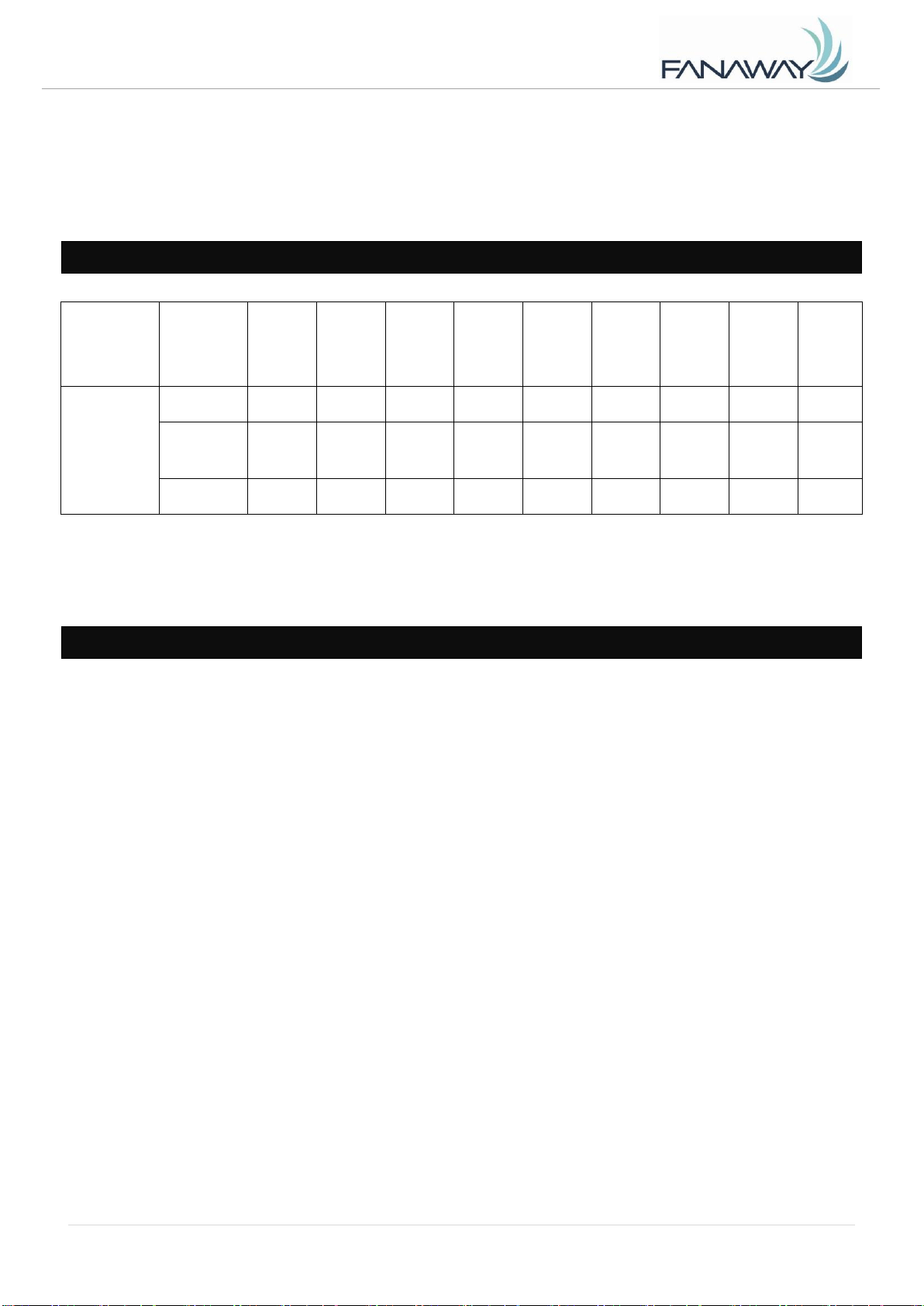
TECHNICAL INFORMATION
Fan Size
Speed
Volts
(V)
Amps
(A)
Watts
(W)
RPM
CFM
CFM/
W
N.W.
(lbs)
G.W.
(lbs)
C.F.
BI-48" FAN
IN-E26-XXX
Extra-High
120
0.47
56.36W
207
4172.69
74.03
24.64
29.15
5.05
Medium
High
120
0.36
32.59W
160
3029.29
92.95
24.64
29.15
5.05
Low
120
0.27
19.37W
119
2115.13
109.19
24.64
29.15
5.05
These are approximate measurements. They do not include data for any lamps or fixtures attached to
the ceiling fan.
WARRANTY
1 year warranty covers the entire fan. Please refer to warranty card for the details.
Fanaway Alistair Installation Instructions
13 | P age
A L I S T A I R - M E N A R D S V e r s i o n 1 . 0 1 2 / 2 0 1 9
GRACIAS POR SU COMPRA
Gracias por adquirir este producto de calidad Fanaway. Para garantizar un funcionamiento correcto y
seguro, lea y siga todas las instrucciones antes de montar, instalar y usar este ventilador de techo. Por
favor, guarde estas instrucciones para futuras consultas.
MEDIDAS DE SEGURIDAD
Lea y guarde estas instrucciones
Este producto cumple con la norma 507 de UL.
1. ADVERTENCIA - Para evitar posibles descargas eléctricas, corte la corriente que va a la caja
eléctrica desde el disyuntor del cuadro eléctrico.
2. ADVERTENCIA - Para reducir el riesgo de incendio, descarga eléctrica o lesión, móntelo a una caja
eléctrica clasificada como «Apta para sostener ventiladores de 70 lb (31,8 kg) o más», y utilice los
tornillos de montaje suministrados con la caja eléctrica y/o fíjelo directamente a la estructura del
edificio. La mayoría de las cajas eléctricas utilizadas comúnmente para el soporte de alumbrados
puede que no sean apropiadas para sostener el ventilador y deban reemplazarse. Consulte con un
electricista cualificado en caso de duda.
3. ADVERTENCIA - Para reducir el riesgo de incendio o electrocución, evite utilizar el ventilador con
un dispositivo semiconductor para el control de la velocidad.
4. ADVERTENCIA - Para reducir el riesgo de lesión, evite doblar los soportes de las aspas cuando los
instale, cuando equilibre las aspas o al limpiar el ventilador. No trate de insertar objetos por las
aspas en rotación.
5. PRECAUCIÓ N - Todo el cableado debe realizarse cumpliendo con el Código Eléctrico Nacional
(ANSI/NFPA 70) y los reglamentos de electricidad locales. La instalación eléctrica debería
efectuarla un electricista acreditado.
6. Para reducir el riesgo de lesiones a personas, el ventilador debe montarse dejando un espacio
mínimo de 7 pies (2,13 m) desde el lado inferior de las aspas hasta el suelo.
7. Después de realizar las conexiones eléctricas, los conductores empalmados deben reorientarse
hacia arriba y meterse con cuidado en el interior de la caja eléctrica. Los cables deben quedar
apartados, dejando el conductor de tierra y el conductor de tierra del dispositivo a un lado de la caja
eléctrica.
8. Tras someterlo a una serie de pruebas, se ha constatado que este aparato cumple los límites
exigidos para dispositivos digitales pertenecientes a la Categoría B, según lo establecido en la
sección 15 de la legislación de la FCC. Estos límites están diseñados para proporcionar una
protección razonable contra interferencias en instalaciones residenciales. Este aparato genera, usa
y puede irradiar energía en forma de radiofrecuencia. En caso de no ser instalado y utilizado de
Fanaway Alistair Installation Instructions
14 | P age
A L I S T A I R - M E N A R D S V e r s i o n 1 . 0 1 2 / 2 0 1 9
acuerdo con las instrucciones, podría causar interferencias en las comunicaciones de radio.
LISTA DE PIEZAS
Desembale el ventilador de techo con cuidado. Saque todas las piezas y la tornillería.
Deposite todos los componentes sobre una superficie lisa y asegúrese de que no falte ninguno
antes de comenzar el montaje. Si falta alguna pieza, devuelva el producto completo al lugar donde
realizó la compra para que lo examinen o reemplacen.
Compruebe que el ventilador de techo no haya sufrido algún daño durante el transporte. Nunca
utilice o instale producto alguno que parezca sufrir algún daño. Devuelva el producto completo al
lugar donde lo haya adquirido para que lo examinen, reparen o reemplacen.
Examine e identifique las piezas. Consulte la imagen 1.
Imagen 1
Fanaway Alistair Installation Instructions
15 | P age
A L I S T A I R - M E N A R D S V e r s i o n 1 . 0 1 2 / 2 0 1 9
1
Soporte de techo x 1
9
Tornillo para madera x 2
2
Florón x 1
Tornillo para metal x 2
3
Tija con junta esférica x 1
Arandela plana x 2
4
Cubierta del perno y chaveta x 1
Arandela de presión x 2
5
Perno x 1
10
Conector de tuerca x 6
6
Chaveta x 1
13
Cinta para equilibrado x 4
7
Conjunto del ventilador x 1
14
Receptor de la señal remota y mando a
distancia x 1 set
8
Base y pantalla de la lámpara x 1
15
Bombilla LED x 3
INSTALACIÓ N DEL SOPORTE DE TECHO
De no haber una caja eléctrica ya instalada, instale una siguiendo estas instrucciones:
Corte la corriente quitando los fusibles o bajando los interruptores diferenciales.
Asegure la caja eléctrica (A) (no incluida) directamente a la estructura del edifico. Utilice los
materiales y elementos de fijación apropiados (no incluidos). La caja eléctrica y su anclaje deben
ser capaces de soportar el peso del ventilador en movimiento (31,8 kg como mínimo). No utilice una
caja eléctrica de plástico.
Las imágenes más abajo muestran tres maneras diferentes de montar la caja eléctrica (A) (no
incluida).
Este ventilador con sistema colgante puede ser instalado en un techo con una inclinación máxima de 15
grados. Imagen 4
NOTA: Si está instalando el ventilador en un techo inclinado, puede que sea necesario utilizar una tija
más larga para mantener el espacio necesario entre la punta del aspa y el techo.
NOTA: El ventilador de techo debe instalarse en un lugar en el que las puntas de las aspas estén a 300
mm cómo mínimo de las paredes y objetos más cercanos.
NOTA: Para la instalación en un techo inclinado, el orificio del soporte de techo (B) debe apuntar hacia
el pico del techo.
Imagen 2
Imagen 3
Imagen 4
Techo inclinado
Máximo 15°
Fanaway Alistair Installation Instructions
16 | P age
A L I S T A I R - M E N A R D S V e r s i o n 1 . 0 1 2 / 2 0 1 9
Para poder colgar su ventilador en un lugar que solo disponga de montantes sin vigas, puede que
necesite instalar una barra sostenedora (C) como la mostrada en la imagen 5. Asegúrese de que la
barra sostenedora que adquiera haya sido diseñada para usarse con ventiladores de techo.
INSTALACIÓ N DEL VENTILADOR
INSTALACIÓ N DE LA TIJA (Imagen 6)
1. Pase la tija (5) a través del florón (4) y de la cubierta del perno y la chaveta (6).
2. Quite la junta esférica (2) aflojando los tornillos (3); inserte los cables del motor por la tija; y vuelva a
asegurar la junta esférica a la tija.
3. Inserte la tija en el acoplamiento (7), alinee los agujeros del acoplamiento con los agujeros de la tija,
e inserte el perno (8). A continuación, inserte la chaveta (9) por el extremo del perno.
4. Por último, asegure la tija al acoplamiento apretando los dos tornillos (10) del acoplamiento. Imagen
6
Imagen 5
Imagen 6
Fanaway Alistair Installation Instructions
17 | P age
A L I S T A I R - M E N A R D S V e r s i o n 1 . 0 1 2 / 2 0 1 9
INSTALACIÓ N DEL VENTILADOR
INSTALACIÓ N DEL KIT DE ILUMINACIÓ N (Imágenes 7 y 8)
1. Afloje el tornillo (1) del soporte del ventilador. Alinee los dos tornillos de cabeza ranurada con las
ranuras de llave (2) del soporte del kit de iluminación. (Imagen 7)
2. Gire la lámpara en el sentido antihorario hasta que los tornillos de cabeza ranurada estén
correctamente posicionados en los extremos de las ranuras (2).
3. Vuelva a apretar el tornillo (1) al soporte de la pantalla. Apriete los tres tornillos. No apriete en
exceso.
4. Conecte el conector rápido al portalámparas (3). (Imagen 8)
5. Asegure el portalámparas (3) al soporte del kit de iluminación apretando los 3 tornillos. No apriete en
exceso.
6. Instale las bombillas (4) en el portalámparas. No exceda la potencia nominal máxima.
7. Instale la pantalla seguido de la arandela y la tuerca (6). Apriete la tuerca (6).
8. Instale el embellecedor (7) y apriete la tuerca (8).
Imagen 7
Imagen 8

Fanaway Alistair Installation Instructions
18 | P age
A L I S T A I R - M E N A R D S V e r s i o n 1 . 0 1 2 / 2 0 1 9
CÓ MO COLGAR EL VENTILADOR
Pase los cables de la corriente (C) de la caja eléctrica del techo (B) por el centro del soporte de techo
(D). Fije el soporte de techo (D) a la caja eléctrica (B) con los tornillos (F) incluidos con la caja eléctrica y
las arandelas (E) incluidas con el ventilador. Imagen 9
Levante el conjunto del ventilador y móntelo en el soporte de techo. Asegúrese de que la ranura de llave
(A) de la junta esférica esté posicionada sobre la clavija de llave (B) del soporte de techo (C) para evitar
la rotación del ventilador cuando esté funcionando. Imagen 10
Imagen 9
Imagen 10
Fanaway Alistair Installation Instructions
19 | P age
A L I S T A I R - M E N A R D S V e r s i o n 1 . 0 1 2 / 2 0 1 9
DIAGRAMA DEL CABLEADO ELÉCTRICO
ADVERTENCIA: Para evitar posibles descargas eléctricas, asegúrese de que la corriente esté cortada
en el cuadro eléctrico.
Siga los pasos siguientes para conectar el ventilador al cableado residencial. Utilice los conectores de
tuerca incluidos con su ventilador. Asegure los conectores con cinta aislante. Asegúrese de que no haya
conexiones o hilos de cable sueltos.
1. Conecte el cable de fase
doméstico (negro) al cable de entrada del
receptor (negro, CA EN L), como muestra
la imagen 11.
2. Conecte el cable neutro
doméstico (blanco) al cable de entrada del
receptor (blanco, CA EN N).
3. Conecte el cable de tierra
doméstico al cable de tierra del soporte
del ventilador (verde) y al cable de tierra
del cuerpo del ventilador.
4. Conecte el cable de salida del
receptor (negro, A MOTOR L) al cable de
entrada de fase del motor (negro, A
MOTOR L).
5. Conecte el cable de salida del
receptor (blanco, A MOTOR N) al cable de
entrada de neutro del motor (blanco, A
MOTOR N).
6. Conecte el cable de salida del
receptor (azul, PARA LUZ) al cable de
entrada de fase de la luz del ventilador
(azul, PARA LUZ).
7. Tras conectar los cables, apártelos unos de
otros de manera que los cables verdes y blancos queden
a un lado de la caja eléctrica y los cables negro y azul
queden al otro lado.
8. Oriente los conectores de tuerca hacia arriba y
meta los cables hacia en el interior de la caja eléctrica.
9. Introduzca con cuidado el receptor de la señal
remota por encima de la junta esférica y métalo en el
espacio que quede dentro del soporte de techo. Procure
no dañar o aflojar los cables.
Imagen 11
Fanaway Alistair Installation Instructions
20 | P age
A L I S T A I R - M E N A R D S V e r s i o n 1 . 0 1 2 / 2 0 1 9
CÓ MO FINALIZAR LA INSTALACIÓ N
Deslice hacia arriba el florón y alinéelo con el soporte de techo. Asegúrese de que todo el cableado
eléctrico quede dentro del florón y de no dañar los cables durante este paso. Fije el florón al soporte de
techo utilizando los tornillos suministrados.
CÓ MO USAR SU VENTILADOR DE TECHO
AJUSTE DE LOS INTERRUPTORES DIP
Cuando haya dos o más ventiladores próximos, es aconsejable ajustar el transmisor/receptor de cada
ventilador con un código diferente, de manera que el funcionamiento de un ventilador no afecte al del
otro.
Los interruptores DIP del receptor se encuentran ubicados sobre la superficie plana del receptor. Los
interruptores DIP del transmisor se encuentran en el compartimento de la batería. Imagen 13
NOTA: Asegúrese de cortar la corriente de antes de ajustar el código.
Cambie la posición de los interruptores DIP en el transmisor y el receptor. Asegúrese de que los
interruptores DIP del receptor remoto coincidan con los del transmisor. En caso de no coincidir, el
transmisor no funcionará. Imagen 14
Imagen 12
Imagen 14
Imagen 13
Interruptores
DIP
Interruptores
DIP
Conector de
las pilas
Ejemplo de configuración de los
interruptores DIP
Receptor 1
Receptor 2
Interruptores DIP
ajustados a 0111
Interruptores DIP
ajustados a 0100
Transmisor 1
Transmisor 2
Interruptores DIP
ajustados a 0111
Interruptores DIP
ajustados a 0100
Fanaway Alistair Installation Instructions
21 | P age
A L I S T A I R - M E N A R D S V e r s i o n 1 . 0 1 2 / 2 0 1 9
INSTALACIÓ N DE LAS PILAS DEL MANDO A DISTANCIA
El mando a distancia funciona con 1 pila de 9 V CC (tamaño). Retire la tapa del compartimiento de las
pilas ubicada en la parte posterior del mando de distancia e instale 1 pila de 9 V CC. Asegúrese de que
los polos estén en la posición correcta mostrada en el conector de la pila. (Pilas incluidas).
CÓ MO USAR EL MANDO A DISTANCIA:
Antes de empezar a utilizar el mando a distancia, dedique un tiempo a leerse esta sección y
familiarizarse con los botones y la función de cada botón.
Indicador led
El indicador led rojo en la parte superior del transmisor parpadeará
cuando se accione algún botón.
BOTONES DEL MANDO A DISTANCIA
HI: Pulse este botón para ajustar el ventilador a una velocidad alta.
MED: Pulse este botón para ajustar el ventilador a una velocidad
moderada.
LOW: Pulse este botón para ajustar el ventilador a una velocidad baja.
OFF: Pulse este botón para apagar el ventilador.
BOTÓ N DE CONTROL DE LA LUZ:
Pulse este botón para apagar o encender la luz.
Mantenga pulsado el botón para acceder a las funciones de regulación
de la luz.
El mando a distancia tiene una función de memoria. Si el ventilador o la luz son apagadas desde el
interruptor de desconexión, memorizará y recuperará su último estado cuando vuelva a encenderla.
INSTALACIÓ N DEL PORTAMANDO
Instale el portamando en la pared con los dos tornillos suministrados y cuelgue el mando en él.
Imagen 16
Imagen 15
Fanaway Alistair Installation Instructions
22 | P age
A L I S T A I R - M E N A R D S V e r s i o n 1 . 0 1 2 / 2 0 1 9
DESPUÉS DE LA INSTALACIÓ N
BAMBOLEO:
NOTA: Los ventiladores de techo tienden a moverse cuando están en funcionamiento debido a que
están montados sobre una arandela de goma. Si el ventilador está montado rígidamente al techo, se
podrían generar demasiadas vibraciones. Unos pocos centímetros de movimiento es bastante
aceptable y NO indica que haya un problema.
CÓ MO REDUCIR EL BAMBOLEO DEL VENTILADOR: Compruebe que todos los tornillos que fijan el
soporte del ventilador y la tija estén bien apretados.
CÓ MO EQUILIBRAR UN VENTILADOR DE TECHO QUE SE BALANCEA:
Por comodidad, se incluye un kit de equilibrado. Siga este procedimiento para equilibrar el ventilador:
1) Instale el ventilador sin el kit de iluminación antes de
equilibrar el ventilador.
2) Defina la placa base en cuatro áreas (puntos A, B, C y D).
Utilice un peso del kit de equilibrado para pegarlo levemente
en el borde de la placa base (punto A). Si el bamboleo
empeora, retire el kit de equilibrado y péguelo levemente al
lado opuesto (punto C). Si el balanceo empeora, vaya al
punto adyacente B o D. Si el bamboleo se reduce, adhiera el
peso con seguridad en dicha ubicación de la placa base.
3) Una vez equilibrado el ventilador, monte el kit de iluminación en la base de iluminación.
RUIDO:
En los momentos silenciosos (sobre todo por la noche), puede que escuche ocasionalmente ruidos
tenues. Leves fluctuaciones de la corriente y frecuencias de señales superpuestas en la corriente para
el control del agua caliente durante las horas no punta pueden causar cambios en el ruido del motor del
ventilador. Esto es algo normal. Por favor, permita un periodo de rodaje de 24 horas, transcurridos los
cuales la mayoría de los ruidos asociados con su nuevo ventilador deberían desaparecer. Todos los
motores eléctricos son audibles hasta cierto punto. Entienda que esto no es un fallo del producto y por
lo tanto no está cubierto por la garantía.
CUIDADO Y LIMPIEZA
NOTA: Apague siempre el ventilador desde el interruptor general de la corriente antes de llevar a
cabo cualquier tarea de mantenimiento o limpieza.
1) La limpieza de su ventilador de techo cada 6 meses es el único mantenimiento que se requiere.
Utilice un cepillo blando o un paño que no deje pelusa para no arañar la capa de pintura. Por favor,
corte la corriente cuando haga esto.
2) No remoje o sumerja el ventilador de techo en agua u otros líquidos. Esto podría dañar el motor o
las aspas y dar pie a posibles descargas eléctricas.
Fanaway Alistair Installation Instructions
23 | P age
A L I S T A I R - M E N A R D S V e r s i o n 1 . 0 1 2 / 2 0 1 9
3) Asegúrese de que el ventilador no entre en contacto con disolventes orgánicos o detergentes.
4) Para limpiar las aspas del ventilador, pase solo un paño humedecido SIN disolventes orgánicos ni
detergentes.
5) El motor tiene un rodamiento con lubricación permanente, por lo que no es necesario engrasarlo.
INFORMACIÓ N TÉCNICA
Dimension
es del
ventilador
Velocida
d
Voltios
(V)
Amper
ios
(A)
Vatios
(W)
RPM
CFM
CFM/
W
Peso
neto
(lb)
Peso
bruto
(lb)
C.F.
BI-48" FAN
IN-E26-XXX
Extra alta
120
0,47
56,36 W
207
4172,69
74,03
24,64
29,15
5,05
Moderada
mente alta
120
0,36
32,59 W
160
3029,29
92,95
24,64
29,15
5,05
Baja
120
0,27
19,37 W
119
2115,13
109,19
24,64
29,15
5,05
Estas son medidas aproximadas. No incluyen datos de ninguna de las lámparas o alumbrados que
vayan instalados al ventilador de techo.
GARANTÍA
El ventilador en su conjunto está cubierto por una garantía de 1 año. Por favor, consulte la tarjeta de
garantía para más información.