For customer support, please contact:
Tel: +1 (949) 800 8488 Email: [email protected] www.beaconlighting.us
US Patent 8317470, 8807938, 8790085, 9255584, 8851841
V1.0 (10/2021)
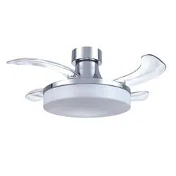
FANAWAY XIAO
CEILING FAN
• INSTALLATION
• OPERATION
• MAINTENANCE
• WARRANTY INFORMATION
CAUTION
READ INSTRUCTIONS CAREFULLY FOR SAFE
INSTALLATION AND FAN OPERATION.
Fanaway Xiao Installation Instructions
2 | P a g e
X I A O - M E N A R D S V e r s i o n 1 . 0 10/ 2 0 21
THANK YOU FOR PURCHASING
Thank you for purchasing this quality Fanaway product. To ensure correct function and safety, please
read and follow all instructions before assembly, installation and use of this ceiling fan. Please keep
instructions for future reference.
SAFETY PRECAUTIONS
Read and Save These Instructions
This product conforms to UL standard 507.
1. WARNING -To avoid possible electrical shock, before installing or servicing your fan, disconnect
the power by turning off the circuit breaker of the fuse box to the outlet box.
2. WARNING - To reduce the risk of fire, electric shock, or personal injury, mount to outlet box marked
“acceptable for fan support of 35 lbs (15.9 kg) or more” and use the mounting screws provided with
the outlet box and/or support directly from building structure. Most outlet boxes commonly used for
the support of luminares may not be acceptable for fan support and may need to be replaced.
Consult a qualified electrician if in doubt. When mounted directly to the building structure, appliance
installation shall not expose combustible material and do not install the appliance to a ceiling with
combustible finish. The installation of the appliance cannot leave the wood of the rafters or any
thermal insulation exposed to the interior of the room.
3. WARNING - To reduce the risk of fire or electric shock, do not use this fan with any solid-state
speed control device.
4. WARNING - To reduce the risk of personal injury, do not bend the blade brackets when installing
the blade brackets balancing the blades, or cleaning the fan. Do not insert foreign objects in
between rotating fan blades.
5. CAUTIONS - All wiring must be in accordance with the National Electrical Code (ANSI/NFPA 70)
and local electrical codes. If you are unfamiliar with wiring, use a qualified electrician.
6. To reduce the risk of injury to person, the fan must be mounted with a minimum of 2.1 Meters (7
feet) clearance from the bottom edge of the blades to the floor.
7. After marking electrical connections, spliced conductors should be turned upward and pushed
carefully up into the outlet box. The wires should be spread apart with the grounded conductor and
the equipment-grounding conductor on one side of the outlet box and the ungrounded conductor
on the other side of the outlet box.
8. This equipment has been tested and found to comply with the limits for a Class B digital device,
pursuant to part 15 of the FCC rules. These limits are to provide reasonable protection against
harmful interference in a residential installation. This equipment generates, uses and can radiate
radio frequency energy and if not installed and used in accordance with the instructions may cause
Fanaway Xiao Installation Instructions
3 | P a g e
X I A O - M E N A R D S V e r s i o n 1 . 0 10/ 2 0 21
harmful interference to radio communications.
9. CAUTION - To reduce the risk of electric shock, disconnect the electrical supply circuit to the fan
before installing light kit.
10. The light kit plate with shade weight is 3.6kg
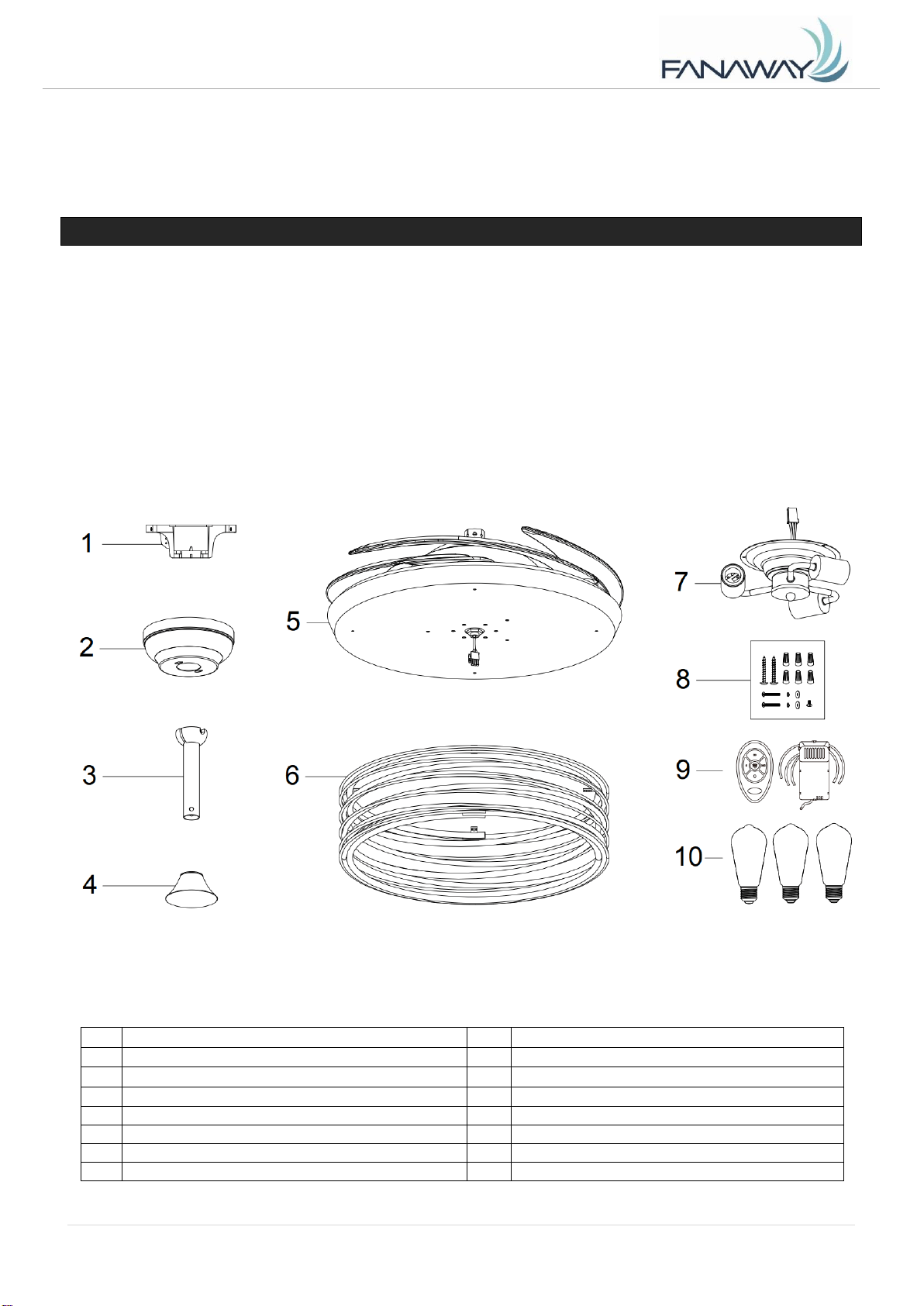
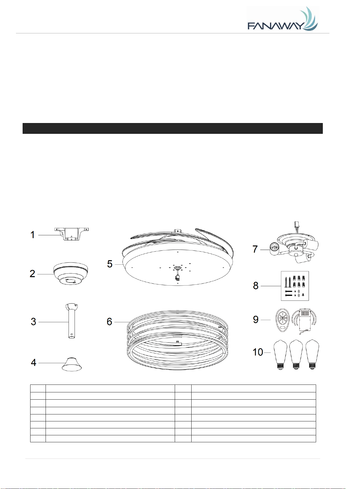
PARTS LIST
• Unpack your ceiling fan and carefully. Remove all parts and hardware.
• Lay out all the components on a smooth surface and make sure there are no components missing
before assembling. If parts are missing, return the complete product to the place of purchase for
inspection or replacement.
• Check whether the ceiling fan has been damaged during transport. Do not operate/install any
product which appears damaged in any way. Return the complete product to the place of purchase
for inspection, repair or replacement.
• Examine and identify the parts. Please refer to Fig 1.
1
Mounting bracket x 1
8
• Wood screw x 2
2
Canopy x 1
• Machine screw x 2
3
Down rod with ball joint x 1
• Flat washer x 2
4
Bolt and pin cover x 1
• Spring washer x 2
5
Fan assembly x 1
⚫ Wire nut x 6
6
Shade x 1
⚫ Spare screw x1
7
Lamp base x 1
9
Receiver & Remote x 1 Set
10
LED bulb x 3
Fig. 1
Fanaway Xiao Installation Instructions
4 | P a g e
X I A O - M E N A R D S V e r s i o n 1 . 0 10/ 2 0 21
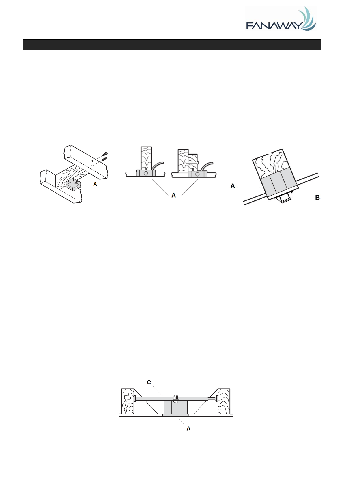
INSTALLING THE MOUNTING BRACKET
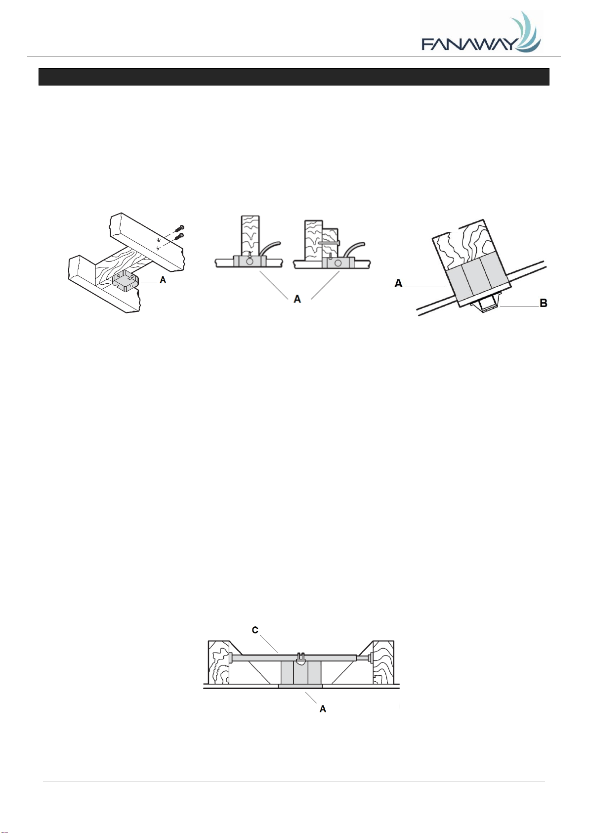
If there isn’t an existing outlet box, then install one using the following instructions:
• Disconnect the power by removing the fuses or turning off the circuit breakers.
• Secure the outlet box (A) (not included) directly to the building structure. Use appropriate fasteners
and materials (not included). The outlet box and its bracing must be able to fully support the weight
of the moving fan (at least 35 lbs). Do not use a plastic outlet box.
• Figures below show three different ways to mount the outlet box (A) (not included).
This fan hanging system supports a maximum 13 degree angled ceiling installation. Fig. 4
NOTE: If you are installing the ceiling fan on a sloped ceiling, you may need a longer downrod to
maintain proper clearance between the tip of the blade and the ceiling.
NOTE: The ceiling fan must be installed in a location so that the blades are spaced 300mm from the tip
of the blade to the nearest objects or walls.
NOTE: For angled ceiling installation, the opening of the mounting bracket (B) must be pointed toward
the peak.
To hang your fan where there is an existing fixture but no ceiling joist, you may need an installation
hanger bar (C) as shown in Fig.5. Make sure the hanger bar you purchase has been designed for use
with ceiling fans.
Fig. 2
Fig. 5
Fig. 3
Fig. 4
Angled ceiling
Maximum 13°
Fanaway Xiao Installation Instructions
5 | P a g e
X I A O - M E N A R D S V e r s i o n 1 . 0 10/ 2 0 21
INSTALLING THE FAN
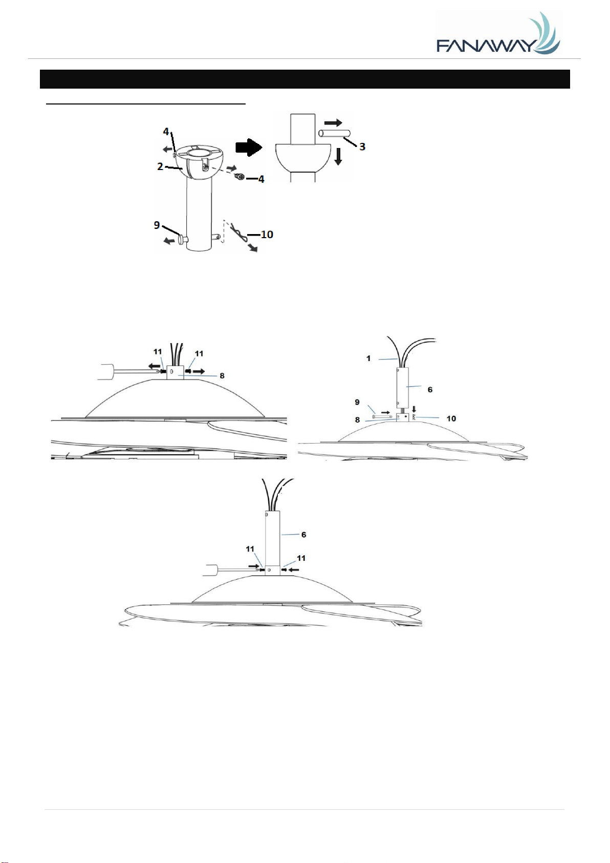
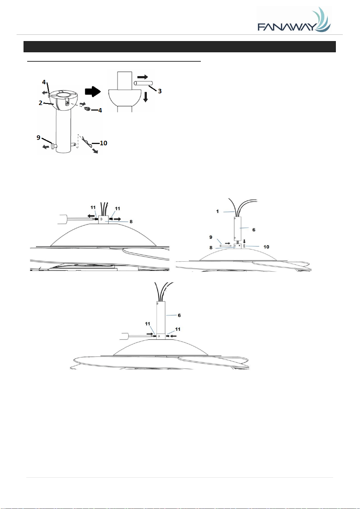
INSTALLING THE DOWN ROD (Fig. 6)
1. Remove the ball joint (2) and dowel pin (3) by loosening the set screws (4) from the down rod (6).
Remove the hitch pin (9) by removing the lock clip (10) (Fig. 6.1). NOTE: Do not discard keep these
parts, they are required to reassemble later.
2. Loosen the set screws (11) on the down rod coupling housing (8). (Fig. 6.2)
3. Carefully feed the fan wires (1) up through the down rod (6). (Fig. 6.3)
4. Assemble the down rod (6) into the down rod coupling housing (8), by inserting and line up the down
rod coupling housing holes with the down rod holes and insert the hitch pin (9) and secure with the lock
clip (10). (Fig. 6.3)
5. Secure the down rod (6) by tightening the set screws (11). (Fig. 6.4)
Fig. 6.1
Fig. 6.4
Fig. 6.2
Fig. 6.3
Fanaway Xiao Installation Instructions
6 | P a g e
X I A O - M E N A R D S V e r s i o n 1 . 0 10/ 2 0 21
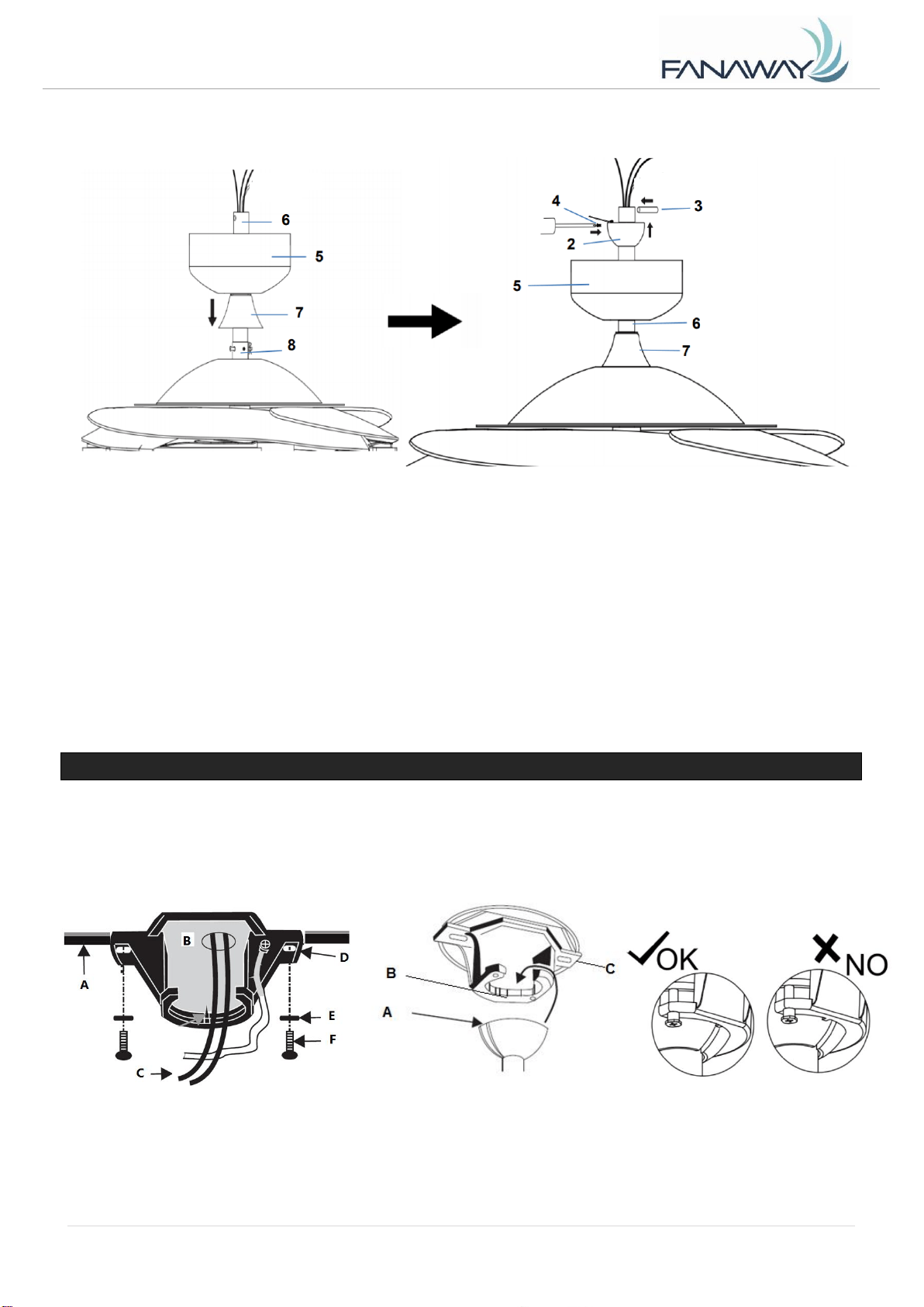
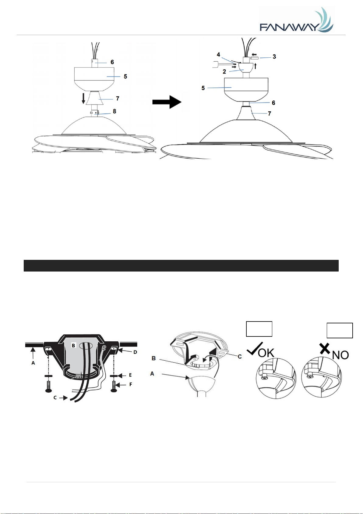
6. Insert the decorative cover (7) onto the down rod (6) to cover the down rod coupling housing (8).(Fig.
6.5)
7. Insert the canopy (5) over the down rod (6) and install the ball joint (2) and dowel pin (3) back onto
the down rod (6) and secure by tightening the set screws (4). (Fig. 6.5 and Fig. 6.6)
HANGING THE FAN
Pass the power supply wires (C) from the ceiling outlet box (B) through the center of the ceiling
mounting bracket (D). Install the ceiling mounting bracket (D) on the outlet box (B) with the mounting
screws (F) provided with the outlet box and washers (E) provided with fan. Fig. 7
Lift the fan assembly onto the mounting bracket. Ensure the key slot (A) of the hanger ball is positioned
on the key pin (B) of the mounting bracket (C) to prevent the fan from rotating when in operation. Fig.8
Fig. 6.6
Fig. 6.5
Fig. 7
Fig. 8
Fanaway Xiao Installation Instructions
7 | P a g e
X I A O - M E N A R D S V e r s i o n 1 . 0 10/ 2 0 21
FAN INSTALLATION
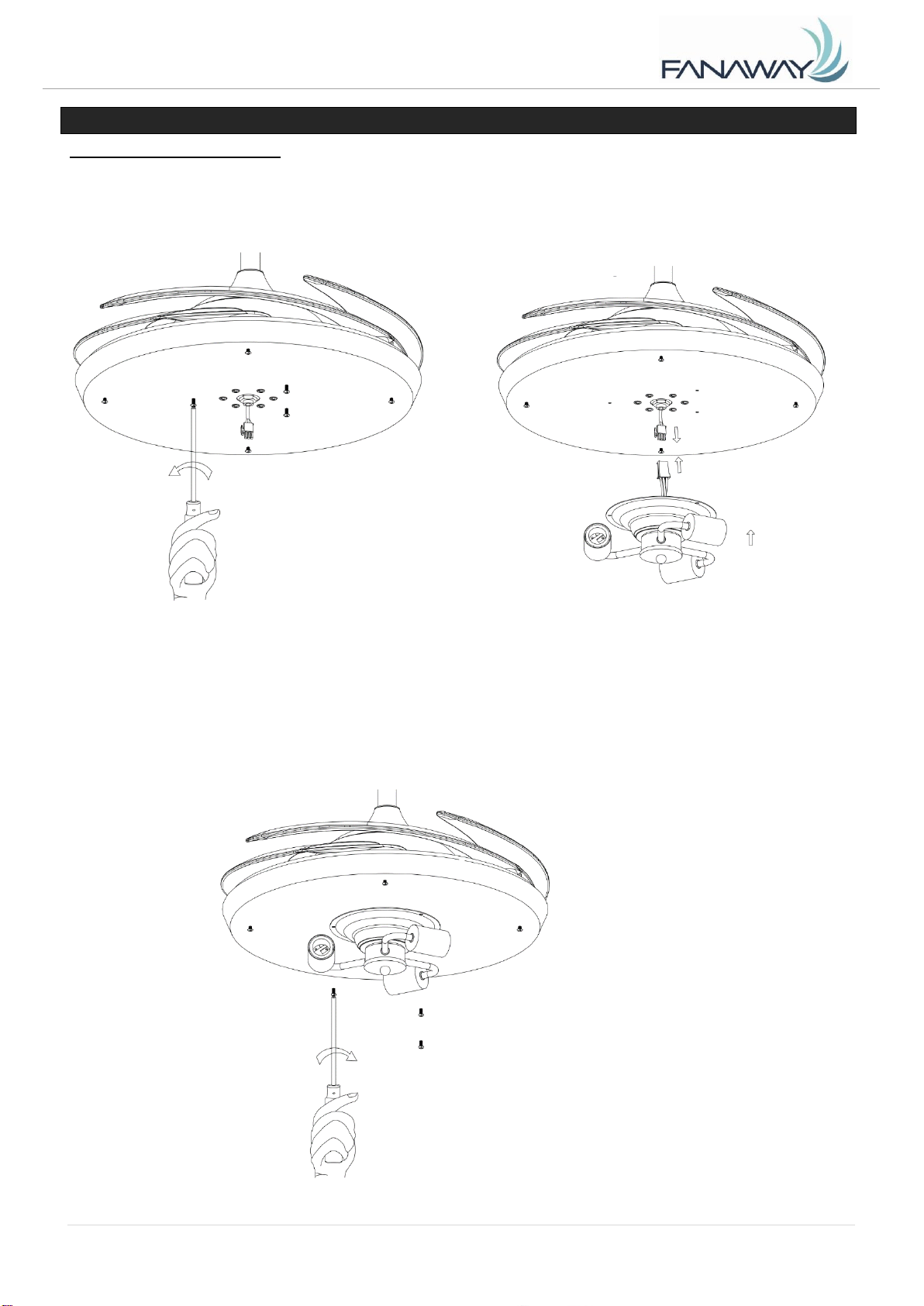
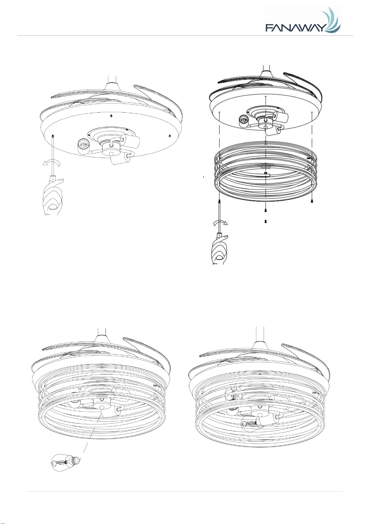
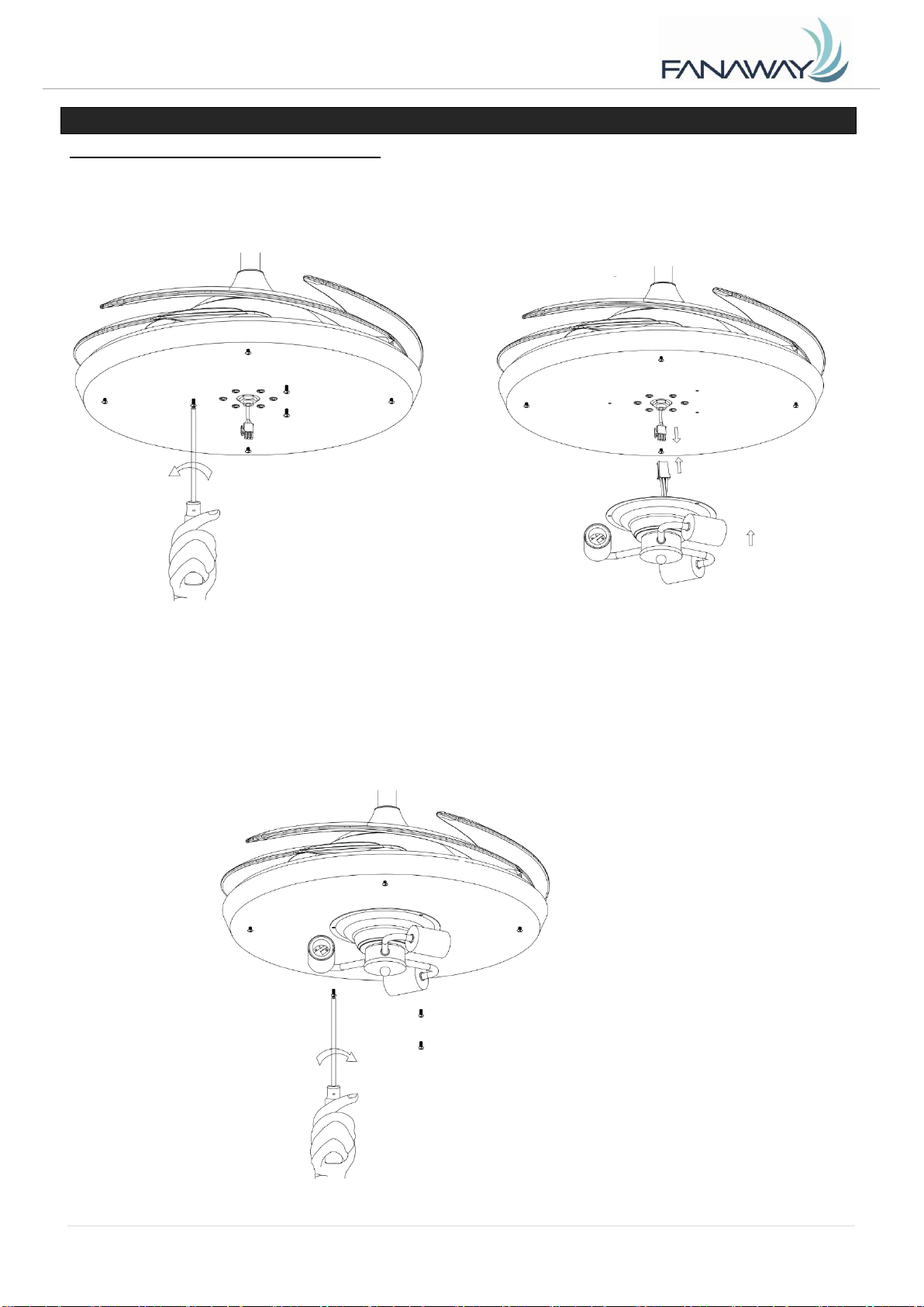
LIGHT KIT INSTALLATION
1. Loosen the 3 pcs screws from the light kit bracket plate. (Fig. 9)
2. Connect the quick connector to the lamp holder part. (Fig. 10)
3. Secure the lamp-holder part to the light kit bracket plate by tightening the 3 screws. Do not over-
tighten. (Fig. 11)
Fig. 11
Fig. 10
Fig. 9
Fanaway Xiao Installation Instructions
8 | P a g e
X I A O - M E N A R D S V e r s i o n 1 . 0 10/ 2 0 21
4. Loosen the 3 pcs screws from the light kit bracket plate. (Fig. 12)
5. Secure the lamp shade to the light kit bracket plate by tightening the 3 screws. Do not over-tighten.
(Fig. 13)
6. Install the globes to the lamp holders. Do not exceed the maximum power rating. (Fig. 14)
Fig. 12
Fig. 14
Fig. 13
Fanaway Xiao Installation Instructions
9 | P a g e
X I A O - M E N A R D S V e r s i o n 1 . 0 10/ 2 0 21
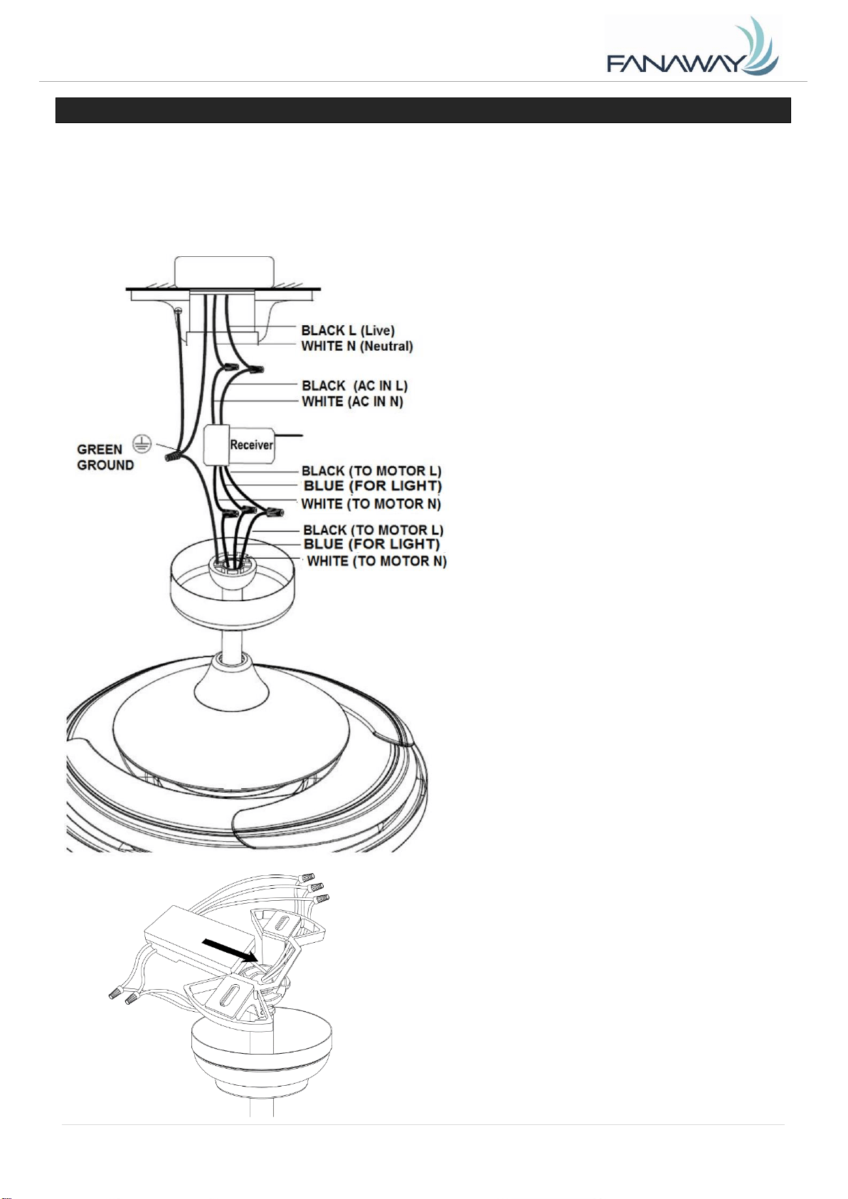
ELECTRICAL WIRING DIAGRAM
WARNING: To avoid possible electrical shock, be sure you have turned off the power at the main circuit
panel.
Follow the steps below to connect the fan to your household wiring. Use the wire connecting nuts
supplied with your fan. Secure the connectors with electrical tape. Make sure there are no loose wire
strands or connections.
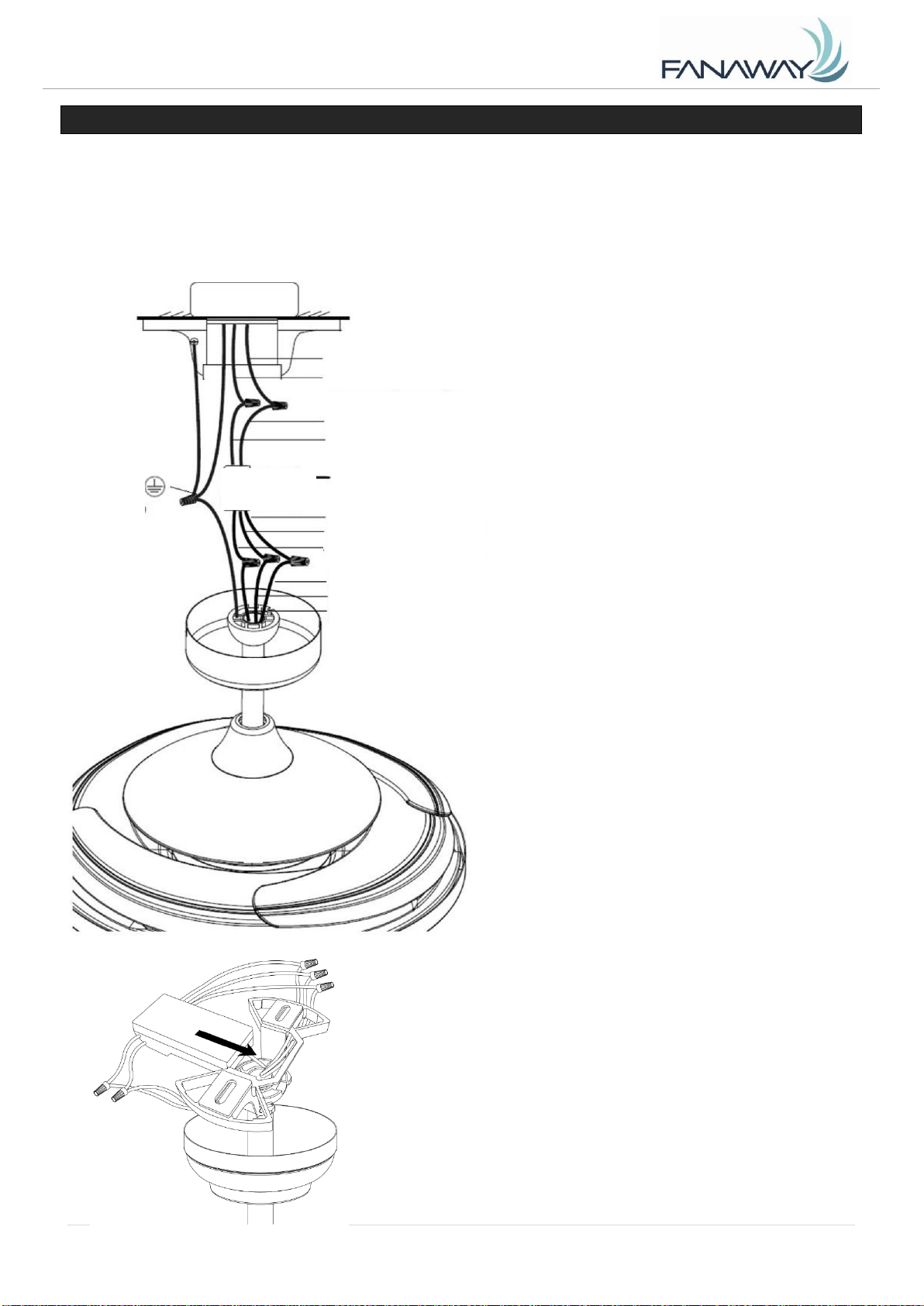
1. Connect the household live supply
wire (black) to receiver input wire (black, AC
IN L) as shown in Fig. 15.
2. Connect the household neutral
supply wire (white) to the receiver input wire
(white, AC IN N).
3. Connect the household ground wire
to the fan bracket ground wire (green) and fan
body ground wire.
4. Connect the reveiver output wire
(black, TO MOTOR L) to motor live input wire
(black, TO MOTOR L).
5. Connect the receiver output wire
(white, TO MOTOR N) to motor neutral input
wire (white, TO MOTOR N)
6. Connect the receiver output wire
(blue, FOR LIGHT) to fan light live input wire
(blue, FOR LIGHT)
7. After connecting the wires, spread
them apart so that the green and white wires
are on one side of the outlet box and the
black and blue wires are on the other side.
8. Turn the connecting nuts upward
and push the wiring into the outlet box.
Fig. 15
9. Carefully insert the Remote Receiver above
the hanger ball in the remainder spacing in the
mounting bracket. Take care not to damage or
loosen any of the wiring. (Fig. 16)
Fig. 16

Fanaway Xiao Installation Instructions
10 | P a g e
X I A O - M E N A R D S V e r s i o n 1 . 0 10/ 2 0 21
FINISHING THE INSTALLATION
INSTALLATION OF THE CANOPY (Fig.17)
• Loosen the 2 screws at the bottom of the mouthing bracket.
• Slide the canopy up to the mounting bracket and align the key holes on the canopy with the screws on
the mounting bracket. Turn the canopy until it locks into place with the narrow section of the key holes
and secure it by tightening the two screws. Ensure all electrical wiring is tucked inside the canopy
and that the wires are not damaged during this step.
Fig. 17
USING YOUR CEILING FAN
Pairing Transmitter and Receiver – when 2 or more ceiling fans are installed in one location
When two or more fans are located near each other, you may want to have the receiver/transmitter for
each fan set to a different code, so that the operation of one fan does not affect the operation of the
other fan/s. The DIP switches for the transmitter (remote hand piece) are located in the battery
compartment of the transmitter. Configuring the DIP switches will allow a unique transmission code
assigned to each fan ceiling.
NOTE: Ensure that you have installed a single pole disconnection switch in the fixed wiring for each fan.
NOTE: Ensure power to the receiver is ON prior to pairing the transmitter with the receiver.
Transmitter / Receiver pairing for Ceiling fan 1:
⚫ Turn OFF the mains supply to the receivers of both ceiling fans 1 and 2.
⚫ Install the 12V battery in the compartment. Please make sure the polarity of the battery is
correct.
Change the position of the DIP switches in the transmitter 1, (Fig. 18)
so that it will be different to transmitter 2. (Fig. 19)
⚫ Turn on the power to receiver 1. Keep the power OFF to receiver 2. (Each ceiling fan must
have its own isolation switch, so that only the ceiling fan that needs to be paired with the
transmitter will be ON).
⚫ Press and hold the Any button of transmitter 1 in excess of 3 seconds within 60 seconds of
switching the power ON to the receiver of ceiling fan 1.

Fanaway Xiao Installation Instructions
11 | P age
X I A O - M E N A R D S V e r s i o n 1 . 0 10/ 2 0 21
If the fan has light kit attached, the light will flash on and off to indicate the paring process is
activated.
⚫ Turn ON and change the speed of the ceiling fan 1 by the transmitter 1 to check the operation and
successful pairing
⚫ If pairing has been unsuccessful, repeat these set of steps again.
Transmitter / Receiver pairing for Ceiling fan 2:
⚫ Turn off the mains supply to the receivers of both ceiling fans 1 and 2.
⚫ Install the 12V battery in the compartment. Please make sure the polarity of the battery is correct.
⚫ Change the position of the DIP switches in the transmitter 2, (Fig. 18)
so that it will be different to transmitter 1. (Fig. 19)
⚫ Turn on the power to receiver 2. Keep the power OFF to receiver 1. (Each ceiling fan must have its
own isolation switch, so that only the ceiling fan that needs to be paired with the transmitter will be
ON).
Press and hold the Any button of transmitter 2 in excess of 3 seconds within 60 seconds of
switching the power ON to the receiver of ceiling fan 2.
If the fan has light kit attached, the light will flash on and off to indicate the paring process is
activated.
⚫ Turn ON and change the speed of ceiling fan 2 by the transmitter 2 to check the operation and
successful pairing.
⚫ If pairing has been unsuccessful, repeat these set of steps again.
Note: The pairing of the transmitter and receiver is not required if only one ceiling fan is
installed. When more than two ceiling fans are installed near each other, please refer to the
instruction above.
Fig. 19
Fig. 18
Fanaway Xiao Installation Instructions
12 | P a g e
X I A O - M E N A R D S V e r s i o n 1 . 0 10/ 2 0 21
INSTALLING THE REMOTE BATTERY
1 x 23A 12V (size) battery is required to operate the remote control. Remove the battery cover from the
back of the remote and 1 x 23A 12V (size) battery. Ensure the polarities are correct as shown on the
battery connector. (Batteries included.)
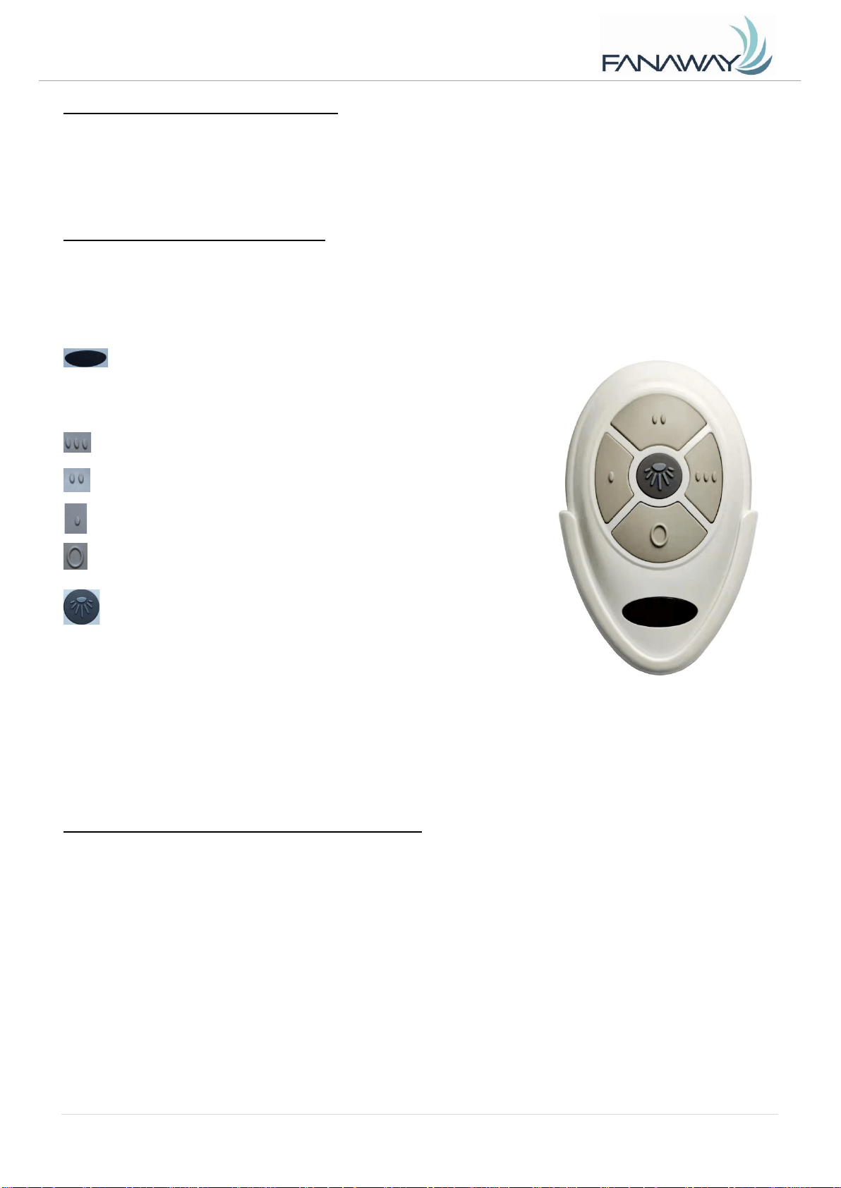
OPERATING THE REMOTE: (Fig.20)
Before you start using the remote, take the time to read through this section and get familiar with the
buttons and function of each button.
LED Indicator
The red LED indicator on the bottom of the transmitter will
flash when the buttons are active.
BUTTONS ON THE REMOTE
: Press the button to set fan running at High speed.
: Press the button to set fan running at Medium speed.
: Press the button to set fan running at Low speed.
: Press the button to turn OFF the fan.
LIGHT CONTROL BUTTON:
Press the button to turn the light ON/OFF.
Press and hold the button to access the light dimming function.
The remote has memory function. If the fan or light is turned off by the isolating switch, it will memorise
and recover the last status when turned on next.
REPAIRING THE FAN RECEIVER & REMOTE PAIRING
Should the remote and receiver lose control after installation or during use, the pairing of the
remote and the receiver must be repaired. Below are the operating symptoms and method to
repair the pairing of the ceiling fan remote and receiver.
Issues:
⚫ Loss of control - Fan is only running at high speed after installation
⚫ Loss of control - No reverse function after installation
⚫ Loss of control - Remote cannot communicate with receiver
Solution:
Fig. 20
Fanaway Xiao Installation Instructions
13 | P a g e
X I A O - M E N A R D S V e r s i o n 1 . 0 10/ 2 0 21
A. Switch OFF the main power to the ceiling fan for 30 seconds.
B. Press and hold the Any button on remote for in excess of 3 seconds within 60 seconds of switching
the power ON to the receiver of the ceiling fan.
If the fan has light kit attached, the light will flash on and off to indicate the paring process is
activated.
C. Turn ON and change the speed of the ceiling fan via the remote to check the operation and
successful pairing.
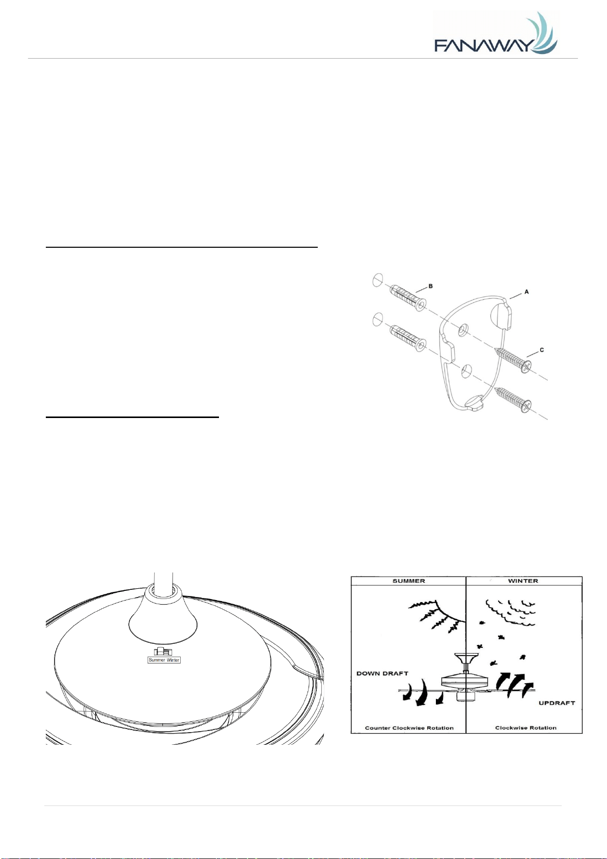
INSTALLING THE TRANSMITTER HOLDER (Fig.21)
Install the holder(A) to the wall with two wall plugs(B)& two screws(C) provided, hang up the transmitter
by the holder.
REVERSING FUNCTION (Fig. 22)
Your ceiling fan can operate in either summer or winter mode.
SUMMER Mode: The reverse switch should be in the SUMMER position to rotate the fan in an
anticlockwise direction. The airflow will be directed downwards, for cooling in summer.
WINTER Mode: The reverse switch should be in the WINTER position to rotate the fan in a clockwise
direction. The airflow will be directed upwards assisting in the circulation of warm air, for energy
conservation in winter.
Fig. 22
Fig. 21
Fanaway Xiao Installation Instructions
14 | P a g e
X I A O - M E N A R D S V e r s i o n 1 . 0 10/ 2 0 21
AFTER INSTALLATION
WOBBLE:
NOTE: ceiling fans tend to move during operation due to the fact that they are mounted on a rubber
grommet. If the fan was mounted rigidly to the ceiling it would cause excessive vibration. Movement of
a few centimetres is quite acceptable and DOES NOT suggest any problem.
TO REDUCE THE FAN WOBBLE: Please check that all screws which fix the mounting bracket and
down rod are secure.
NOISE:
When it is quiet (especially at night) you may hear occasional small noises. Slight power fluctuations
and frequency signals superimposed in the electricity for off-peak hot water control, may cause a
change in fan motor noise. This is normal. Please allow a 24-hour “breaking -in” period, most noises
associated with a new fan disappear during this time. All electric motors are audible to some extent.
Please note that this is not a product fault, and as such is not covered under warranty.
CARE & CLEANING
NOTE: Always turn OFF the power at the mains switch before performing any maintenance or
attempting to clean your fan.
1) Every 6 months periodic cleaning of your ceiling fan is the only maintenance required. Use a soft
brush or lint free cloth to avoid scratching the paint finish. Please turn OFF electricity power when
you do so.
2) Do not soak or immerse your ceiling fan in water or other liquids. It could damage the motor or the
blades and create the possibility of an electrical shock.
3) Ensure that the fan does not come in contact with any organic solvents or cleaners.
4) To clean the fan blade, wipe with only a damp clean cloth with NO organic solvents or cleaners.
5) The motor has a permanently lubricated ball bearing so there is no need to oil.
TECHNICAL INFORMATION
Fan Size
Speed
Volts
(V)
Amps
(A)
Watts
(W)
RPM
CFM
CFM/
W
N.W.
(lbs)
C.F.
BI-48" XIAO-01-
E26-XXX
Extra-High
120
0.52
61.84W
203
4153.53
67.17
21.83
4.04
Low
120
0.36
21.39W
139
2180.42
101.94
21.83
4.04
These are approximate measurements. They do not include data for any lamps or fixtures attached to
the ceiling fan.
WARRANTY
1 year warranty covers the entire fan. Please refer to warranty card for the details.
Fanaway Xiao Installation Instructions
15 | P a g e
X I A O - M E N A R D S V e r s i o n 1 . 0 10/ 2 0 21
GRACIAS POR SU COMPRA
Gracias por adquirir este producto Fanaway de calidad. Para garantizar el correcto funcionamiento y la
seguridad de este ventilador de techo, antes de armarlo, instalarlo y usarlo lea y siga todas las
instrucciones. Conserve estas instrucciones para consultas en el futuro.
MEDIDAS DE SEGURIDAD
Lea y conserve estas instrucciones
Este producto está conforme con el estándar UL 507.
1. ADVERTENCIA - Para evitar cualquier posible descarga eléctrica, antes de instalar o reparar su
ventilador desconecte la alimentación apagando el disyuntor del circuito de la caja de fusibles a la
caja de salida.
2. ADVERTENCIA: para reducir el riesgo de incendio, descarga eléctrica o lesiones personales,
ensámblelo en la caja de tomacorriente marcada como "apta para soportar un ventilador de 35 lbs
(15.9 kg) o más" y use los tornillos de montaje proporcionados con la caja de tomacorriente y/o
instálelo directamente en la estructura del edificio. La mayoría de las caja tomacorrientes usadas
normalmente para el soporte de la luminarias no son aptas para el soporte de los ventiladores y
puede ser necesario reemplazarlas. En caso de duda, consulte con un electricista calificado.
Cuando se monta directamente en la estructura del edificio, la instalación del aparato no debe
exponer material combustible y no debe instalar el aparato en un techo con acabado combustible.
La instalación del aparato no puede dejar la madera de las vigas ni ningún aislamiento térmico
expuesto al interior de la habitación.
3. ADVERTENCIA - Para disminuir el riesgo de incendio o descarga eléctrica, no use este ventilador
con dispositivos de control de velocidad de estado sólido.
4. ADVERTENCIA - Para disminuir el riesgo de que se produzcan lesiones personales, no doble los
soportes de las aspas al instalarlos para equilibrar las aspas o al limpiar el ventilador. No inserte
objetos extraños entre las aspas giratorias del ventilador.
5. PRECAUCIONES - Todo el cableado debe estar conforme con el Código Eléctrico Nacional
(ANSI/NFPA 70) y los códigos eléctricos locales. Si no está familiarizado con el cableado, emplee
a un electricista calificado.
6. Para disminuir el riesgo de sufrir lesiones personales, el ventilador debe ubicarse a una distancia
mínima de 2.1 metros (7 pies) entre el borde de la parte inferior de las aspas y el suelo.
7. Después de hacer las conexiones eléctricas, los conductores empalmados se deben voltear hacia
arriba y empujar con cuidado al interior de la caja de salida. Los cables deben separarse con el
conductor conectado a tierra y el conductor de conexión a tierra del equipo en un lado de la caja
de salida y el conductor sin conexión a tierra en el otro lado de la caja de salida.
8. Este equipo fue probado y se demostró que cumple con los límites de un dispositivo digital de
Fanaway Xiao Installation Instructions
16 | P a g e
X I A O - M E N A R D S V e r s i o n 1 . 0 10/ 2 0 21
Clase B, según la parte 15 de las reglas de la FCC. Estos límites se establecieron para
proporcionar una protección razonable contra la interferencia dañina en una instalación residencial.
Este equipo genera, usa y puede radiar energía de frecuencias de radio y, de no instalarse y
utilizarse de acuerdo con las instrucciones, puede causar interferencia dañina con las
comunicaciones de radio.
9. PRECAUCIÓN - Para reducir el riesgo de descarga eléctrica, desconecte el circuito de suministro
eléctrico del ventilador antes de instalar el juego de luces.
10. La placa del juego de luces con el peso de la pantalla es de 3.6 kg.
LISTA DE PIEZAS
• Desempaque su ventilador de techo con cuidado. Saque todas las piezas y los tornillos.
• Deposite todos los componentes sobre una superficie lisa y verifique que no falta ninguno antes de
iniciar el armado. Si falta alguna pieza, regrese el producto completo al lugar donde lo adquirió para
que lo examinen o reemplacen.
• Compruebe si el ventilador de techo se dañó durante el transporte. No ponga en funcionamiento ni
instale ningún producto que presente cualquier tipo de daño. Regrese el producto completo al lugar
donde lo adquirió para que lo examinen, reparen o reemplacen.
• Examine e identifique las piezas. Consulte la Fig. 1.
1
1 soporte de montaje
8
• 2 tornillos para madera
2
1 florón
• 2 tornillos de máquina
3
1 varilla descendente con junta de bola
• 2 arandelas planas
4
1 cubierta de perno y clavija
• 2 arandelas de resorte
5
1 conjunto de ventilador
⚫ Tuerca para cable x 6
6
Pantalla x 1
⚫ Tornillo de repuesto x1
7
Base de lámpara x 1
9
1 juego de receptor y control remoto
10
3 focos LED
Fig. 1
Fanaway Xiao Installation Instructions
17 | P a g e
X I A O - M E N A R D S V e r s i o n 1 . 0 10/ 2 0 21
INSTALACIÓN DEL SOPORTE DE ARMADO
Si no hay ya una caja de salida, instale una siguiendo estas instrucciones:
• Desconecte el suministro eléctrico retirando los fusibles o apagando los disyuntores de circuito.
• Fije la caja de salida (A) (no incluida) directamente a la estructura del edificio. Use fijaciones y
materiales apropiados (no incluidos). La caja de salida y su soporte deben ser capaces de soportar
completamente el peso del ventilador en movimiento (al menos 35 lbs). No use una caja
tomacorrientes de plástico.
• Las imágenes siguientes muestran tres tipos distintos de montaje de la caja de salida (A) (no
incluida).
Este sistema colgante del ventilador soporta un ángulo máximo de 13 grados en la instalación de techo.
Fig. 4
NOTA: Si va a instalar el ventilador en un techo inclinado, es posible que necesite una varilla
descendente más larga para mantener el espacio necesario entre la punta del aspa y el techo.
NOTA: El ventilador de techo debe instalarse en un lugar donde las puntas de las aspas queden a una
distancia de 300 mm del objeto o pared más cercano.
NOTA: Al instalar en techos en ángulo, la abertura del soporte de armado (B) debe apuntar hacia el
pico.
Para colgar el ventilador donde ya existe una luminaria pero no hay una viga de techo, es posible que
necesite instalar una barra de colgado (C) como se ilustra en la Fig. 5. Asegúrese de que la barra de
colgado que compra se ha diseñado para utilizarse con ventiladores de techo.
Fig. 2
Fig. 5
Fig. 3
Fig. 4
Techo en ángulo
Máximo 13°
Fanaway Xiao Installation Instructions
18 | P a g e
X I A O - M E N A R D S V e r s i o n 1 . 0 10/ 2 0 21
INSTALACIÓN DEL VENTILADOR
INSTALACIÓN DE LA VARILLA DESCENDENTE (Fig. 6)
1. Retire la junta de bola (2) y el pasador cilíndrico (3) aflojando los tornillos de fijación (4) de la varilla
descendente (6). Retire el pasador de enganche (9) quitando el clip de bloqueo (10). (Fig. 6.1). NOTA:
No deseche estas piezas, consérvelas; se requerirá volver a armarlas más tarde.
2. Afloje los tornillos de fijación (11) de la caja de acoplamiento de la varilla descendente (8). (Fig. 6.2)
3. Pase con cuidado los cables del ventilador (1) hacia arriba a través de la varilla descendente (6).
(Fig. 6.3)
4. Monte la varilla descendente (6) en la caja de acoplamiento de la varilla descendente (8), insertando
y alineando los orificios de la caja de acoplamiento de la varilla descendente con los orificios de la
varilla descendente e inserte el pasador de enganche (9) y asegúrelo con el clip de bloqueo (10). (Fig.
6.3)
5. Asegure la varilla descendente (6) ajustando los tornillos de fijación (11). (Fig. 6.4
Fig.6.1
Fig. 6.4
Fig. 6.2
Fig. 6.3
Fanaway Xiao Installation Instructions
19 | P a g e
X I A O - M E N A R D S V e r s i o n 1 . 0 10/ 2 0 21
6. Inserte la cubierta decorativa (7) en la varilla descendente (6) para cubrir la caja de acoplamiento de
la varilla descendente (8).(Fig. 6.5)
7. Inserte el dosel (5) sobre la varilla descendente (6) e instale nuevamente la junta de bola (2) y el
pasador cilíndrico (3) en la varilla descendente (6) y asegúrelos ajustando los tornillos de fijación (4).
(Fig. 6.5 y Fig. 6.6)
CÓMO COLGAR EL VENTILADOR
Pase los cables de alimentación eléctrica (C) de la caja de salida del techo (B) a través del centro del
soporte de armado en el techo (D). Instale el soporte de montaje en el techo (D) en la caja
tomacorrientes (B) con los tornillos de armado (F) suministrados con la caja tomacorrientes y las
arandelas (E) incluidas con el ventilador. Fig. 7
Eleve el conjunto del ventilador sobre el soporte de montaje. Compruebe que la ranura de la llave (A)
de la bola de colgado está ubicada en la clavija de la llave (B) del soporte de montaje (C) para evitar
que el ventilador gire cuando está en funcionamiento. Fig.8
Fig. 6.6
Fig. 6.5
Fig. 7
Fig. 8
OK
NO
Fanaway Xiao Installation Instructions
20 | P a g e
X I A O - M E N A R D S V e r s i o n 1 . 0 10/ 2 0 21
INSTALACIÓN DEL VENTILADOR
INSTALACIÓN DEL JUEGO DE LUCES
1. Afloje los 3 tornillos de la placa de soporte del juego de luces. (Fig.9)
2. Conecte el conector rápido a la pieza del soporte de la lámpara. (Fig. 10)
3. Fije la pieza del soporte de la lámpara a la placa del soporte del juego de luces ajustando los 3
tornillos. No los apriete en exceso. (Fig.11)
Fig. 11
Fig. 10
Fig. 9

Fanaway Xiao Installation Instructions
21 | P a g e
X I A O - M E N A R D S V e r s i o n 1 . 0 10/ 2 0 21
4. Afloje los 3 tornillos de la placa de soporte del juego de luces. (Fig. 12)
5. Asegure la pantalla de la lámpara a la placa de soporte del juego de luces apretando los 3 tornillos.
No los apriete en exceso. (Fig.13)
6. Instale las lámparas en los portalámparas. No exceda la potencia máxima nominal. (Fig. 14)
Fig. 12
Fig. 14
Fig. 13
Fanaway Xiao Installation Instructions
22 | P a g e
X I A O - M E N A R D S V e r s i o n 1 . 0 10/ 2 0 21
DIAGRAMA DE CABLEADO ELÉCTRICO
ADVERTENCIA: Para evitar cualquier posible descarga eléctrica, asegúrese de haber desconectado la
alimentación eléctrica en el panel de circuito general.
Siga los pasos que aparecen a continuación para conectar el ventilador al cableado de su casa. Use
las tuercas de conexión de cable que se suministran con su ventilador. Fije los conectores con cinta
eléctrica. Asegúrese de que no haya hilos de cables sueltos o conexiones flojas.
1. Conecte el cable vivo de suministro
eléctrico del hogar (negro) al cable de
entrada del receptor (negro, AC IN L) como
se muestra en la Fig. 15
2. Conecte el cable neutro de la
alimentación de la casa (blanco) al cable de
entrada del receptor (blanco, CA DENTRO
NEUTRO).
3. Conecte el cable a tierra de la casa
al cable a tierra del soporte del ventilador
(verde) y al cable a tierra del cuerpo del
ventilador.
4. Conecte el cable de salida del
receptor (negro AL MOTOR VIVO) al cable
de entrada vivo del motor (negro, AL MOTOR
VIVO).
5. Conecte el cable de salida del
receptor (blanco, AL MOTOR NEUTRO) al
cable de entrada neutro del motor (blanco, AL
MOTOR NEUTRO).
6. Conecte el cable de salida del
receptor (azul, PARA LA LUZ) al cable de
entrada vivo de la luz del ventilador (azul,
PARA LA LUZ)
7. Después de conectar los cables, sepárelos de manera
que el cable verde y el cable blanco estén en un lado de la caja
de la caja de salida y el cable negro y el cable azul estén en el
otro lado.
8. Gire las tuercas de conexión hacia arriba y presione el
cableado hacia el interior de la caja de salida.
9. Inserte el receptor remoto con cuidado sobre la bola de
colgado en el espacio sobrante del soporte de montaje. Tenga
cuidado de no dañar ni aflojar nada del cableado. (Fig. 16)
Fig. 15
Fig. 16
CONEXIÓN A
TIERRA
VERDE
Receptor
NEGRO (vivo)
BLANCO (neutro)
NEGRO (CA DENTRO
VIVO)
BLANCO (CA
DENTRO NEUTRO)
NEGRO (AL MOTOR
VIVO)
AZUL (PARA LA LUZ)
BLANCO (AL MOTOR
NEUTRO)
NEGRO (AL MOTOR
VIVO)
AZUL (PARA LA LUZ)
BLANCO (AL MOTOR
NEUTRO)
Fanaway Xiao Installation Instructions
23 | P a g e
X I A O - M E N A R D S V e r s i o n 1 . 0 10/ 2 0 21
CÓMO FINALIZAR LA INSTALACIÓN
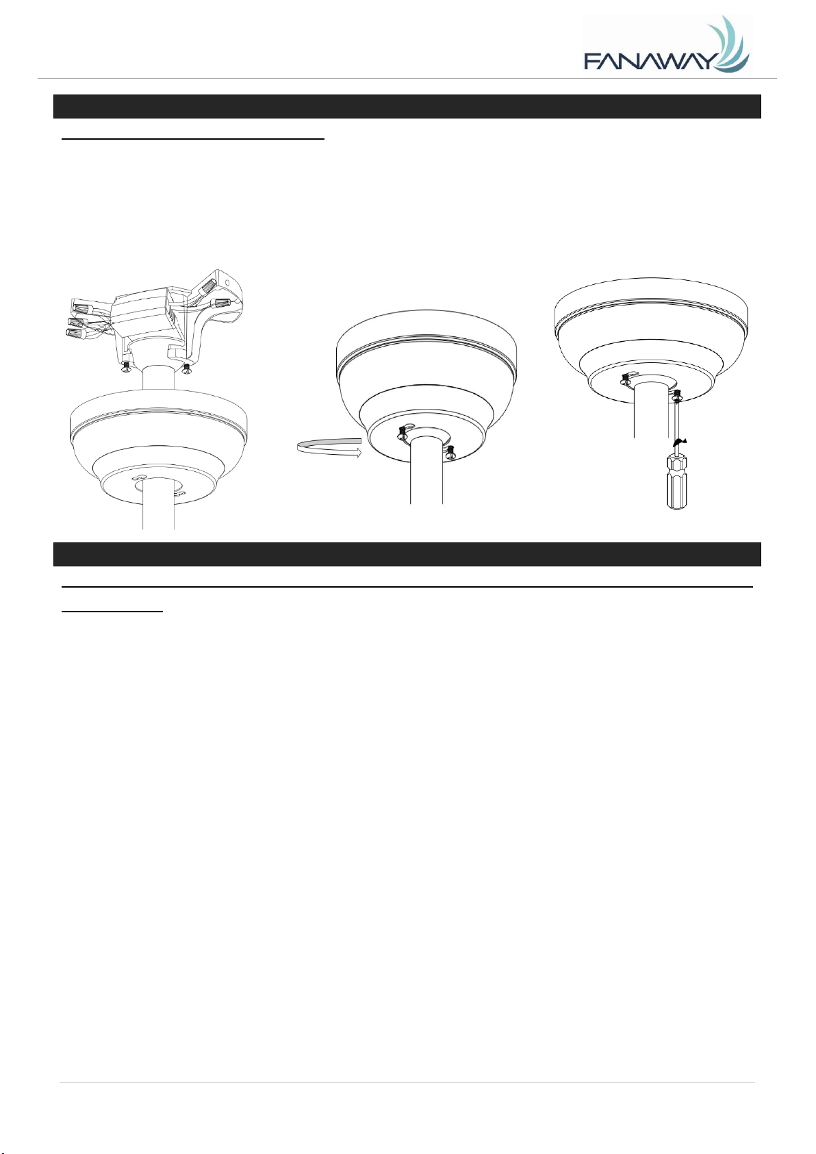
INSTALACIÓN DEL FLORÓN (Fig.17)
• Afloje los 2 tornillos en la parte inferior del soporte de montaje.
• Deslice el florón hasta el soporte de montaje y alinee los orificios clave en el florón con los tornillos en
el soporte de montaje. Gire el florón hasta que se bloquee en su lugar con la sección angosta de los
orificios clave y asegúrelos ajustando los dos tornillos. Verifique que todo el cableado eléctrico está
introducido en el florón y que los cables no se han dañado al hacerlo.
Fig. 17
USO DE SU VENTILADOR DE TECHO
Emparejamiento de transmisor y receptor: cuando se instalan 2 o más ventiladores de techo en
una ubicación
Cuando uno o más ventiladores se encuentran a poca distancia uno del otro, podría ser conveniente
tener un código diferente para el receptor/transmisor de cada ventilador, de manera que la operación
de un ventilador no afecte a la de los otros ventiladores. Los interruptores DIP para el transmisor (pieza
de mano remota) están ubicados en el compartimiento de la batería del transmisor. La configuración de
los interruptores DIP permitirá un código de transmisión único asignado a cada techo de ventilador.
NOTA: Asegúrese que haya instalado un interruptor de desconexión de un solo polo en el cableado fijo
para cada ventilador.
NOTA: Asegúrese que la corriente en el receptor esté encendida antes de emparejar el transmisor con
el receptor.
Emparejamiento de transmisor / receptor para ventilador de techo 1:
⚫ Apague la alimentación principal a los receptores de las ventiladores de techo 1 y 2.
⚫ Instale la batería de 12V en el compartimiento. Asegúrese que la polaridad de la batería
sea la correcta.
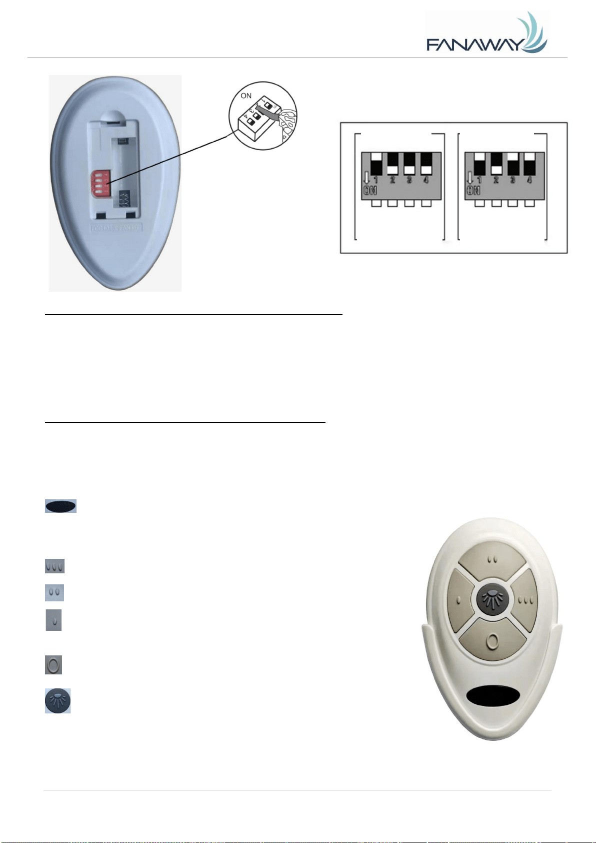
Cambie la posición de los interruptores DIP en el transmisor 1, (Fig. 18)
para que sea diferente al transmisor 2. (Fig. 19)
⚫ Encienda la corriente que va al receptor 1. Mantenga la corriente apagada que va al
receptor 2. (Cada ventilador de techo debe tener su propio interruptor de aislamiento, para
que solo el ventilador de techo tenga que ser emparejado con el transmisor esté

Fanaway Xiao Installation Instructions
24 | P a g e
X I A O - M E N A R D S V e r s i o n 1 . 0 10/ 2 0 21
encendido).
⚫ Mantenga presionado el botón Any (Cualquiera) del transmisor 1 durante más de 3
segundos dentro de los 60 segundos posteriores a encender el receptor del ventilador de
techo 1.
Si el ventilador tiene un juego de luces fijado, la luz va a parpadear on y off para indicar que el
proceso de emparejamiento se ha activado.
⚫ Encienda (ON) y cambie la velocidad del ventilador de techo 1 a través del transmisor 1 para
verificar el funcionamiento y el emparejamiento exitosos.
⚫ Si el emparejamiento no ha sido exitoso, repita este set de pasos nuevamente.
Emparejamiento de transmisor / receptor para ventilador de techo 2:
⚫ Apague la alimentación principal a los receptores de los ventiladores de techo 1 y 2.
⚫ Instale la batería de 12V en el compartimiento. Asegúrese que la polaridad de la batería sea la
correcta.
⚫ Cambie la posición de los interruptores DIP en el transmisor 2, (Fig.18)
para que sea diferente al transmisor 1. (Fig. 19)
⚫ Encienda la corriente que va al receptor 2. Mantenga la corriente en apagado al receptor 1. (Cada
ventilador de techo debe tener su propio interruptor de aislamiento, para que solo el ventilador de
techo tenga que ser emparejado con el transmisor esté encendido).
Mantenga presionado el botón Any (Cualquiera) del transmisor 2 durante más de 3 segundos
dentro de los 60 segundos posteriores a encender el receptor del ventilador de techo 2.
Si el ventilador tiene un juego de luces fijado, la luz va a parpadear on y off para indicar que el
proceso de emparejamiento se ha activado.
⚫ Encienda (ON) y cambie la velocidad del ventilador de techo 2 a través del transmisor 2 para
verificar el funcionamiento y el emparejamiento exitosos.
⚫ Si el emparejamiento no ha sido exitoso, repita este set de pasos nuevamente.
Nota: No es necesario emparejar el transmisor y el receptor si solo se instala un ventilador de
techo. Cuando se instalan más de dos ventiladores de techo uno cerca del otro, consulte las
instrucciones anteriores.
Fanaway Xiao Installation Instructions
25 | P a g e
X I A O - M E N A R D S V e r s i o n 1 . 0 10/ 2 0 21
INSTALACIÓN DE LA BATERÍA DEL CONTROL REMOTO
Para operar el control remoto se requiere 1 batería de 23A de 12V (tamaño). Retire la tapa de la
batería ubicada en la parte posterior del control remoto e inserte 1 batería de 23A de 12V (tamaño).
Compruebe que las polaridades están en dirección correcta como se indica en el conector de la batería.
(Batería incluida)
FUNCIONAMIENTO DEL CONTROL REMOTO: (Fig.20)
Antes de comenzar a usar el control remoto, tómese un tiempo para leer esta sección y familiarizarse
con los botones y la función de cada uno de ellos.
Indicador LED
El indicador LED rojo en la parte inferior del transmisor
parpadeará cuando los botones estén activos.
BOTONES DEL CONTROL REMOTO
: Presione el botón para que el ventilador funcione a velocidad alta.
: Presione el botón para que el ventilador funcione a velocidad
media.
: Presione el botón para que el ventilador funcione a velocidad baja.
: Presione el botón OFF para apagar el ventilador.
BOTÓN DE CONTROL DE LUZ:
Presione el botón para encender o apagar la luz.
Mantenga presionado el botón para acceder a la función de atenuación
de la luz.
Fig. 19
Fig. 18
Fig. 20
ENCENDIDO
Interruptores DIP
Transmisor 1
Interruptores DIP
Establecer en 0111
Transmisor 2
Interruptores DIP
Establecer en 0100
Fanaway Xiao Installation Instructions
26 | P a g e
X I A O - M E N A R D S V e r s i o n 1 . 0 10/ 2 0 21
El control remoto tiene función de memoria. Si el ventilador o la luz se apagan mediante el interruptor
de aislamiento, lo memorizará y restablecerá el último estado al encenderlo de nuevo.
REPARACIÓN DEL RECEPTOR DEL VENTILADOR Y EMPAREJAMIENTO CON EL CONTROL REMOTO
Si el control remoto y el receptor pierden el control después de la instalación o durante el uso,
el emparejamiento del control y el receptor debe ser reparado. A continuación se muestran los
síntomas de funcionamiento y el método para reparar el emparejamiento del control remoto del
ventilador de techo y el receptor.
Problemas:
⚫ Pérdida de control - El ventilador sólo funciona a alta velocidad después de la instalación
⚫ Pérdida de control - No hay función de reversa después de la instalación
⚫ Pérdida de control - El control remoto no puede comunicarse con el receptor
Solución:
A. Desconecte (OFF) la alimentación principal del ventilador de techo por 30 segundos.
B. Presione y mantenga presionado el botón Any (Cualquiera) en el control remoto por más de 3
segundos en un plazo de 60 segundos después de conectar (ON) la corriente al receptor del
ventilador de techo.
Si el ventilador tiene un juego de luces fijado, la luz va a parpadear on y off para indicar que el
proceso de emparejamiento se ha activado.
C. Encienda (ON) y cambie la velocidad del ventilador de techo con el control remoto para verificar el
funcionamiento y el emparejamiento exitosos.
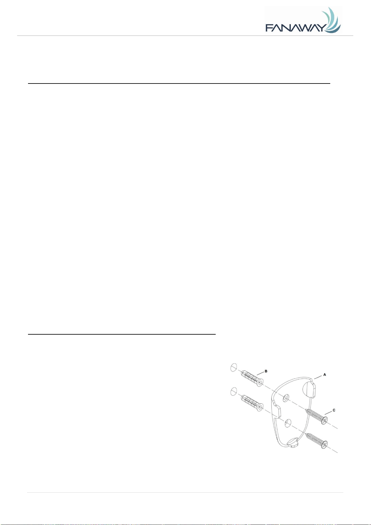
INSTALACIÓN DEL SOPORTE DEL TRANSMISOR (Fig.21)
Instale el soporte (A) a la pared con los dos tarugos de pared (B) y los dos tornillos suministrados (C) y
cuelgue el transmisor del soporte.
Fig. 21
Fanaway Xiao Installation Instructions
27 | P a g e
X I A O - M E N A R D S V e r s i o n 1 . 0 10/ 2 0 21
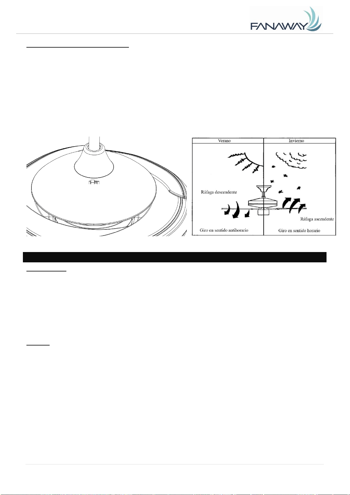
FUNCIÓN DE INVERSIÓN (Fig.22)
Su ventilador de techo posee un modo de verano y un modo de invierno.
Modo de VERANO: El interruptor de inversión de giro debe estar en posición de VERANO para que el
ventilador gire en sentido antihorario. El flujo del aire se dirigirá hacia abajo para refrescar en verano.
Modo de INVIERNO: El interruptor de inversión de giro deberá estar en posición de INVIERNO para
que el ventilador gire en sentido horario. El flujo de aire se dirigirá hacia arriba ayudando a la
circulación del aire caliente para ahorrar energía en invierno.
DESPUÉS DE LA INSTALACIÓN
BAMBOLEO:
NOTA: Los ventiladores de techo tienden a moverse cuando están en funcionamiento debido a que
están armados sobre una arandela de caucho. Si el ventilador se montó en el techo de forma rígida,
esto podría causar una vibración excesiva. Un movimiento de unos centímetros es aceptable y NO
indica problema alguno.
CÓMO REDUCIR EL BAMBOLEO DEL VENTILADOR: Verifique que todos los tornillos que fijan el
soporte de armado y la varilla descendente están seguros.
RUIDO:
Cuando hay silencio (especialmente por la noche), es posible escuchar pequeños ruidos de vez en
cuando. Las fluctuaciones ligeras de suministro eléctrico y las señales de frecuencia superpuestas en
el control de agua caliente fuera de horas pico pueden causar cambios en el ruido del motor del
ventilador. Esto es normal. Deje un periodo de ajuste de 24 horas y la mayoría de los ruidos asociados
con el nuevo ventilador desaparecerán en dicho periodo de tiempo. Todos los motores eléctricos
producen un cierto ruido. Tenga en cuenta que esto no es un problema del producto y que no está
cubierto por la garantía.
Fig. 22
Verano Invierno
Fanaway Xiao Installation Instructions
28 | P a g e
X I A O - M E N A R D S V e r s i o n 1 . 0 10/ 2 0 21
CUIDADOS Y LIMPIEZA
NOTA: Apague siempre el ventilador del interruptor principal antes de realizarle cualquier
operación de mantenimiento o de limpiarlo.
1. El único mantenimiento que necesita el ventilador es una limpieza periódica cada 6 meses. Use un
cepillo suave o un paño sin fibras para evitar arañar el acabado de pintura. Desconecte el
suministro eléctrico antes de hacerlo.
2. No remoje ni sumerja el ventilador en agua ni en otros líquidos. Esto podría dañar el motor o las
aspas y causar descargas eléctricas.
3. No permita que el ventilador entre en contacto con disolventes orgánicos ni con productos de
limpieza.
4. Limpie las aspas solo con un paño húmedo y NO utilice disolventes orgánicos ni productos de
limpieza.
5. El motor posee un rodamiento de bola permanentemente lubricado y no necesita engrasarse.
INFORMACIÓN TÉCNICA
Dimensiones
del ventilador
Velocidad
Voltios
(V)
Amperios
(A)
Vatios
(W)
RPM
CFM
CFM/W
Peso
neto
(lbs)
C.F.
BI-48" XIAO-01-
E26-XXX
Extra alta
120
0.52
61,84 W
203
4153.53
67.17
21.83
4.04
Baja
120
0.36
21.39W
139
2180.42
101.94
21.83
4.04
Estas medidas son aproximadas. No incluyen datos de lámparas o luminarias fijadas al ventilador de
techo.
GARANTÍA
1 año de garantía para todo el ventilador. Consulte la tarjeta de garantía para ver los detalles.