SWAINS
OWNER'S
MANUAL
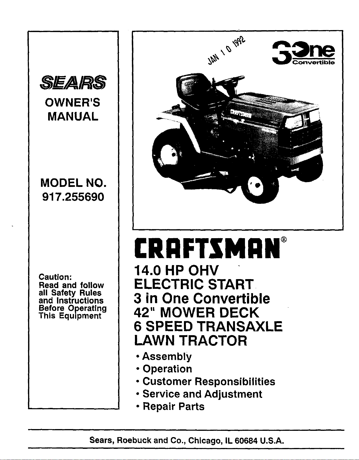
MODEL NO.
917.255690
Caution:
Read and follow
all Safety Rules
and Instructions
Before Operating
This Equipment
£RRFTZMAN
14.0 HP OHV
ELECTRIC START
3 in One Convertible
42" MOWER DECK
6 SPEED TRANSAXLE
LAWN TRACTOR
• Assembly
• Operation
• Customer Responsibilities
• Service and Adjustment
• Repair Parts
i i
Sears, Roebuck and Co., Chicago, IL 60684 U.S.A.
i i
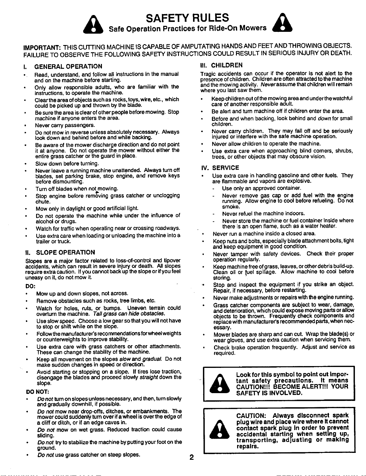
SAFETY RULES
Safe Operation Practices for Ride-On Mowers
IMPORTANT: THIS cu'r-I"ING MACHINE IS CAPABLE OF AMPUTATING HANDS AND FEET AND THROWING OBJECTS.
FAILURE TO OBSERVE THE FOLLOWING SAFETY INSTRUCTIONS COULD RESULT IN SERIOUS INJURY OR DEATH.
It
GENERAL OPERATION
Read, understand, and follow all instructions in the manual
and on the machine before starting.
Only allow responsible adults, who are familiar with the
instructions, to operate the machine.
Clear the area ofobjects such as rocks,toys, wire, etc., which
could be picked up and thrown by the blade.
Be sure the area isclear ofother people before mowing. Stop
machine if anyone enters the area.
Never carry passengers.
Do not mow in reverse unless absolutely necessary. Always
look down and behind before and while backing.
Be aware of the mower discharge direction and do not point
it at anyone. Do not operate the mower without either the
entire grass catcher or the guard in place.
Slow down before turning.
Never leave a running machine unattended. Always turn off
blades, set parking brake, stop engine, and remove keys
before dismounting.
Turn off blades when not mowing.
Stop engine before removing grass catcher or unclogging
chute.
Mow only in daylight or good artificial light.
Do not operate the machine while under the influence of
alcohol or drugs.
Watch for traffic when operating near or crossing roadways.
Use extra care when loading or unloading the machine intoa
trailer or truck.
I1. SLOPE OPERATION
Slopesare a majorfactor relatedto loss-of-controland tipover
accidents,whichcanresultin severeinjuryor death. All slopes
requireextracaution.Ifyoucannotbackuptheslopeorifyoufeel
uneasyon it,do notmow it.
DO:
Mow up and downslopes,notacross.
Removeobstaclessuchas rocks,tree limbs,etc.
Watch for holes, ruts, or bumps. Uneven terrain could
overturnthe machine. Ta/Igrasscanhideobstacles.
Useslowspeed. Choosea lowgearsothatyouwillnothave
to stoporshiftwhile onthe slope.
Followthemanufacturer'srecommendationsforwheelweights
orcounterweightstoimprovestability.
Use extra care with grass catchersor otherattachments.
These canchangethestabilityof themachine.
Keep allmovementonthe slopess/owand gradual. Do not
make suddenchangesin speed ordirection.
Avoid startingor stoppingon a slope. Iftires lose traction,
disengagethe bladesand proceedslowlystraightdownthe
slope.
DO NOT:
Do not turn onslopes unless necessary, and then, turn slowly
and gradually downhill, if possible.
Do not mow near drop-offs, ditches, or embankments. The
mower could suddenly turnover ifa wheel is over the edge of
a cliff or ditch, or if an edge caves in.
Do not mow on wet grass. Reduced traction could cause
sliding.
Do not try to stabilize the machine by putting your foot onthe
ground.
Do not use grass catcher on steep slopes.
IlL CHILDREN
Tragic accidents can occur if the operator is not alert to the
presence of children. Children are often attracted tothe machine
and the mowing activity. Neverassume that children will remain
where you last saw them.
Keep children out of the mowing area and under thewatchful
care of another responsible adult.
Be alert and turn machine off if children enter the area.
Before and when backing, look behind and down for small
children.
Never carry children. They may fall off and be seriously
injured or interfere with the safe machine operation.
Never allow children to operate the machine.
Use extra care when approaching blind comers, shrubs.
trees, or other objects that may obscure vision.
IV, SERVICE
Use extracare inhandlinggasolineand otherfuels. They
are flammable and vaporsare explosive.
Use onlyan approved container.
Never remove gas cap or add fuel with the engine
running.Allowenginetocoolbeforerefueling.Do not
smoke.
Never refuelthe machine indoors.
Never storethemachineor fuel containerinsidewhere
there isan openflame, suchas a waterheater.
Never runa machineinsidea closedarea.
Keepnutsandbolts,especiallybladeattachment bolts,tight
and keep equipmentingoodcondition.
Never tamper with safety devices. Check their proper
operationregularly.
Keepmachinefree ofgrass,leaves,orotherdebrisbuild-up.
Clean oil or _uel spillage. Allow machineto cool before
storing.
_o Stop and inspectthe equipment if you strike an object.
Repair,ifnecessary,beforerestarting.
Nevermakeadjustmentsorrepairswiththeenginerunning.
Grasscatcher componentsare subect to wear, damage,
anddeterioration,whichcouldexposemovingpartsorallow
objectsto be thrown. Frequentlycheck componentsand
replacewithmanufacturer'srecommendedparts,whennec-
essary.
Mowerbladesare sharpand can cut, Wrapthe blade(s)or
wear gloves,and useextracautionwhen servicingthem.
Check brake operationfrequently. Adjustand serviceas
required.
Look for this symbol to point out Impor-
tant safety precautions. It means
CAUTION!!! BECOME ALERT!!! YOUR
SAFETY IS INVOLVED.
I
2
A
CAUT ON: Always disconnect spark
plug wire and place wire where it cannot
contact spark plug In order to prevent
accidental starting when setting up,
transporting, adjusting or making
repairs.

CONGRATULATIONS on your purchase of a Sears
Tractor. It has been designed, engineered and manu-
factured to give you the best possible dependability and
performance.
Should you experience any problem you cannot easily
remedy, please contact your nearest Sears Service
Center/Deparfment. We have competent, well-trained
technicians and the proper tools to service or repair this
unit,
Please read and retain this manual. The instructions will
enable you to assemble and maintainyour unit properly.
Always observe the "SAFETY RULES".
MODEL
NUMBER 917.255690
SERIAL
NUMBER
DATE OF PURCHASE
THE MODELAND SERIAL NUMBERS WILL BE FOUND
ON A PLATE UNDER THE SEAT.
YOU SHOULD RECORDt_OTH SERIAL NUMBER AND
DATE OF PURCHASE AND KEEP IN A SAFE PLACE
FOR FUTURE REFERENCE.
MAINTENANCE AGREEMENT
A Sears Maintenance Agreement is available on this prod-
uct. Contact your nearest Sears store for details.
CUSTOMER RESPONSIBILITIES
Read and observe the safety rules.
Follow a regular schedule in maintaining, caring for and
using your unit.
Follow the instructions under "Customer Responsibili-
ties" and "Storage" sections of this owner's manual.
PRODUCT SPECIFICATIONS
HORSEPOWER: 14.0
GASOLINE CAPACITY: 3.5 GALLONS
UNLEADED REGULAR
OiL (3.0 PINTS) SAE 30 (Above32°F)
(3.5 PINTS) 5W-30 (Below32°F)
SPARKPLUG (GAP.030 IN.): CHAMPION RC12YC
VALVE CLEARANCE: INTAKE.0015 - .0030 IN.
EXHAUST .0020- .0035 IN.
GROUND SPEED: FORWARD
1st1.10 MPH
2nd 1.40 MPH
3rd 2.00 MPH
4th 3.00 MPH
5th 4.20 MPH
6th 5.00 MPH
REVERSE: 1.50 MPH
TIRE PRESSURE: FRONT: 14 PSI
REAR: 10 PSI
CHARGING SYSTEM: 3 AMPS BATFERY
5 AMPS HEADLIGHTS
BLADE BOLT TORQUE: 30-35 FT. LBS.
WARNING: This unitis equipped with an internal combus-
tion engine and should not be used on or near any unim-
proved forest-covered, brush-covered or grass-covered
land unless the engine's exhaust system is equipped with
a spark arrester meeting applicable local or state laws (if
any). Ifa spark arrester is used, itshould be maintained in
effective working order by the operator.
In the state of _California the above is required by law
_Section 4442 of the California Public Resources Code).
Other states may have similar laws. Federal laws apply on
federal lands. A spark arrester for the muffler is available
through your nearest .Sears Authorized Service Center
(See REPAIR PARTS section of this manual).
LIMITED TWO YEAR WARRANTY ON ELECTRIC START RIDING EQUIPMENT
Fortwo (2) years from the date of purchase,if this ridingequipmentis maintained,lubricatedand tuned up accordingto the
instructions in the owner'smanual, Sears will repairor replace,free of charge,any parts found to be defectivein materialor
workmanship.
ThisWarrantydoes notcover:
Expendable itemswhichbecome wornduringnormaluse, suchasblades,sparkplugs,air cleanersandbelts.
Tirereplacementor repaircaused bypuncturesfrom outsideobjects,suchas nails,thorns,stumps,or glass.
Repairsnecessarybecauseofoperatorabuse,negligence, improperstorageor accident orthefailuretomaintainthe
equipment accordingtothe instructionscontainedintheowner'smanual.
Ridingequipmentusedforcommercialor rentalpurposes.
LIMITED 90 DAY WARRANTY ON BATTERY
For90 daysfrom dateofpurchase,ifanybatteryincludedwiththisridingequipment provesdefectiveinmaterialorworkmanship
andourtestingdeterminesthebatterywillnotholda charge,Searswillreplacethe batteryat nocharge.
WARRANTY SERVICE IS AVAILABLE BY RETURNING THE RIDING EQUIPMENT TO THE NEAREST SEARS SERVICE
CENTER/DEPARTMENT IN THE UNITED STATES.
ThisWarrantygivesyou specificlegal rights,and youmay also haveotherrightswhichmay varyfromstatetostate.
SEARS, ROEBUCK AND CO., D/731CR-W, SEARS TOWER, CHICAGO, ILLINOIS 60684
3
TABLE OF CONTENTS
SAFETY RULES ............................................................ 2
PRODUCT SPECIFICATIONS ....................................... 3
CUSTOMER RESPONSIBILITIES ..................... 3, 15-19
WARRANTY ................................................................... 3
TABLE OF CONTENTS ................................................. 4
INDEX ............................................................................. 4
• TRACTOR ACCESSORIES ........................................... 5
ASSEMBLY .............................................................. 7-10
OPERATION ........................................................... 11-14
MAINTENANCE SCHEDULE ...................................... 15
SERVICE AND ADJUSTMENTS ............................ 20-24
STORAGE .................................................................... 25
TROUBLESHOOTING. .......................................... 26-27
REPAIR PARTS - TRACTOR ................................. 30,-45
REPAIR PARTS - ENGINE ..................................... 46-51
PARTS ORDERING/SERVICE ................... BACK PAGE
INDEX
A
Accessories ............................................ 5
Adjustments:
Brake..... L.....'............................... 22
Carburetor ................................... 24
Mower
Front-To-Back .................... :...21
Side-To-Side .......................... 21
Throttle Control Cable ................. 24
Air Filter, Engine ................................. 18
Air Screen, Engine ............................. 18
Assembly ......................................... 7-10
B
Battery:
Charging ........................................ 6
Cleaning ...................................... 17
Installation ..................................... 9
Levels ....................................... 8,17
Preparation .................................... 8
Starting with Weak Battery .......... 23
Storage ........................................ 25
Terminals .................................... 17
Belt:
Motion Drive
Removal/Replacement ........... 22
Mower Blade Drive
Removal/Replacement ........... 22
Blade:
Sharpening .................................. 16
Replacement ............................... t6
Brake Adjustment ............................... 22
C
Carburetor Adjustment ....................... 24
Controls, Tractor ................................. 11
Customer Responsibilities ............. 15-19
Engine:
Air Filter ................................... 18
Air Filter Foam Pre-Cleaner .... 18
Air Screen, Engine .................. 18
Battery ..................................... 17
Engine Oil ................................ 17
Fuel Filter ................................ 19
Spark Plugs ............................. 19
Tractor:
Blade ....................................... 16
Lubrication Chart ..................... 15
Maintenance Schedule ............ 15
Tire Care ......................... 8,16,23
Cutting Height, Mower ........................ 12
E
Electrical:
Schematic ................................... 28
Wiring Diagram ............................ 30
Engine:
Air Filter ....................................... 18
Air Filter Foam Pre-Cleaner ........ 18
Air Screen ................................... 18
Oil Change .................................. 17
Oil Level ................................. 13,17
Oil Type ....................................... 17
Preparation .................................. 13
Repair Parts ........................... 46-51
Starting ........................................ 14
Storage ........................................ 25
F
Filter:
Air Filter ....................................... 18
Air Filter Foam Pre, Cleaner ........ 18
Fuel ............................................. 19
Fuel:
Type ............................................ 13
Storage ........................................ 25
Fuse .................................................... 23
L
Leveling Mower Deck ......................... 21
Lubrication:
Chart ................... _........................ 15
M
Maintenance Schedule ....................... 15
Mower:
Adjustment, Front-to-Back ........... 21
Adjustment, Side-to-Side ............. 21
Blade Sharpening ........................ 16
Blade Replacement ..................... 16
Cutting Height .............................. 12
Installation ................................... 20
Operation ..................................... 13
Removal ...................................... 20
Mowing Tips ....................................... 14
Muffler ................................................. 19
Spark Arrester .......................... 3,40
Mulcher Plate ............................... 10
O
Oil:
Cold Weather Conditions ....... 13,17
Engine ......................................... 17
Storage ........................................ 25
Operation ...................................... 11-14
Operating Mower ................................ 13
Options:
Accessories ................................... 5
Spark Arrester .......................... 3,40
P
Parking Brake ................................ 11-12
Parts Bag .............................................. 6
Parts, Replacement/Repair ........... 30-45
Product Specifications ........................... 3
R
Repair Parts .................................. 30-45
S
Safety Rules ......................................... 2
Seat ...................................................... 8
Service and Adjustments ..............20-24
Carburetor ...................................24
Fuse ............................................ 23
Motion Drive Belt
Removal/Replacement...........22
Mower BladeDrive Belt
Removal/Replacement ...........22
Mower Adjustment
Front- to-Back ........................21
Side-to-Side............................21
Mower Removal ..........................20
Tire Care .............................8,16,23
SlopeGuide Sheet .............................55
Spark Plugs ........................................ t9
Specifications .......................................3
Startingthe Engine ........................ 13-14
SteeringWheel ................................ 7,22
Stopping the Tractor ...........................12
Storage ............................................... 25
T
Throttle Control Cable
Adjustment ..................................24
Tires...................................................8,16,23
Trouble Shooting Chart ..................26-27
Transaxle:
RepairParts........................... 44-45
W
Warranty............................................... 3
WiringDiagram................................... 30
WiringSchematic ...............................28
4
!
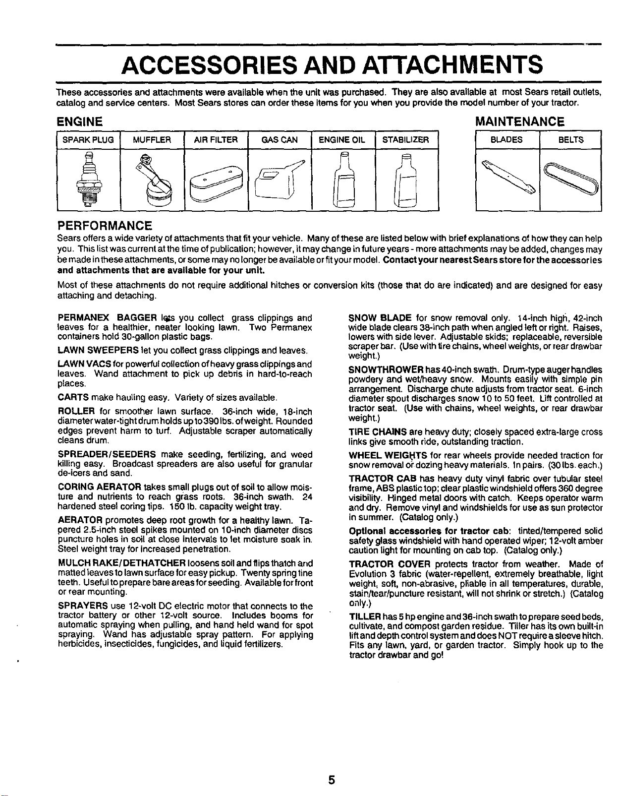
ACCESSORIES AND ATTACHMENTS
i i i ,i
These accessories and attachments were available when the unit was purchased. They are also available at most Sears retail outlets,
catalog and service centers. Most Sears stores can order these items for you when you provide the model number of your tractor.
ENGINE
SPARK PLUG MUFFLER AIR FILTER GAS CAN ENGINE OIL STABILIZER
MAINTENANCE
BLADES BELTS
PERFORMANCE
Sears offers a wide variety of attachments that fit your vehicle. Many of these are listed below with brief explanations of how they can help
you. This listwas current at the time of publication; however, it may change in future years - more attachments may be added, changes may
be made inthese attachments, orsome may nolonger be available orfit your model. Contact your nearest Sears store for the accessories
and attachments that ere available for your unit.
Most of these attachments do not require additional hitches or conversion kits (those that do are indicated) and are designed for easy
attaching and detaching.
PERMANEX BAGGER 16¢syou collect grass clippings and
leaves for a healthier, heater looking lawn. Two Permanex
containers hold 30*gallon plastic bags.
LAWN SWEEPERS let you collect grass clippings and leaves.
LAWN VACS for powerful collection ofheavy grass clippings and
leaves. Wand attachment to pick up debris in hard-to-reach
places.
CARTS make hauling easy. Variety of sizes available.
ROLLER for smoother lawn surface. 36-inch wide, 18-inch
diameter water-tight drum holds up to 390 Ibs. of weight. Rounded
edges prevent harm to turf. Adjustable scraper automatically
cleans drum.
SPREADER/SEEDERS make seeding, fertilizing, and weed
killing easy. Broadcast spreaders are also useful for granular
de-icers and sand.
CORING AERATOR takes small plugs out of soil to allow mois-
ture and nutrients to reach gt:ass roots. 36-inch swath. 24
hardened steel coring tips. 150 lb. capacity weight tray.
AERATOR promotes deep root growth for a healthy lawn. Ta-
pered 2.5-inch steel spikes mounted on 10-inch diameter discs
puncture holes in soil at close intervals to let moisture soak in.
Steel weight tray for increased penetration.
MULCH RAKE/DETHATCHER loosens soiland flips thatch and
matted leaves to lawn surface for easy pickup. Twenty spring line
teeth. Useful to prepare bare areas for seeding. Available for front
or rear mounting.
SPRAYERS use 12-volt DC electric motor that oonnects to the
tractor battery or other 12-volt source. Includes booms for
automatic spraying when pulling, and hand held wand for spot
spraying. Wand has adjustable spray pattern. For applying
herbicides, insecticides, fungicides, and liquid fertilizers.
SNOW BLADE for snow removal only. 14-inch high, 42-inch
wide blade clears 38-inch path when angled lett or right. Raises,
lowers with side lever. Adjustable skids; replaceable, reversible
scraper bar, (Use with tire chains, wheel weights, or rear drawbar
weight.)
SNOWTHROWER has 40-inch swath. Drum-type auger handles
powdery and wet/heavy snow. Mounts easily with simple pin
arrangement. Discharge chute adjusts from tractor seat. 6-inch
diameter spout discharges snow 10 to 50 feet. Liftcontrolled at
tractor seat. (Use with chains, wheel weights, or rear drawbar
weight.)
TIRE CHAINS are heavy duty; closely spaced extra-large cross
links give smooth ride, outstanding traction.
WHEEL WEIGI:'ITS for rear wheels provide needed traction for
snow removal o_"dozing heavy materials. In pairs. (30 Ibs. each,)
TRACTOR CAB has heavy duty vinyl fabric over tubular steel
frame, ABS plastic top; clear plastic windshield offers 360 degree
visibility. Hinged metal doors with catch. Keeps operator warm
and dry. Remove vinyl and windshields for use as sun protector
in summer. (Catalog only.)
Optional accessories for tractor cab: tinted/tempered solid
safety glass windshield with hand operated wiper; 12-volt amber
caution light for mounting on cab top. (Catalog only.)
TRACTOR COVER protects tractor from weather. Made of
Evolution 3 fabric (water-repellent, extremely breathable, light
weight, soft, non-abrasive, pliable in all temperatures, durable,
stain/tear/puncture resistant, will not shrink or stretch.) (Catalog
only.)
TILLER has 5 hpengine and 36-inch swath to prepare seed beds.
cultivate, and compost garden residue. Tiller has its own built-in
lift and depth control system and does NOT require a sleeve hitch.
Fits any lawn, yard, or garden tractor. Simply hook up to the
tractor drawbar and go!
5
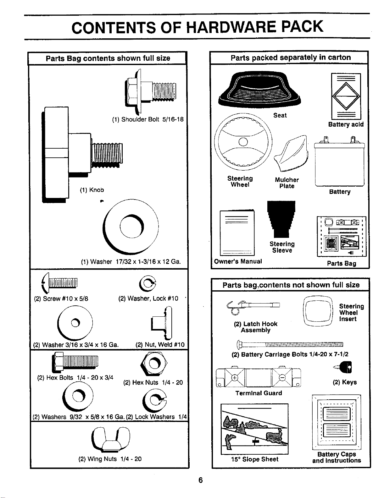
CONTENTS OF HARDWARE PACK
Parts Bag contents shown full size
!
i
(1) Knob
(1) Shoulder Bolt 5/16-18
(1) Washer 17/32 x 1-3/16 x 12 Ga.
(2) Screw #10 x 5/8
(2) Washer 3/16 x 3/4 x 16 Ga.
(2) He× Bolts 1/4 - 20 x 314
(2) Washer, Lock #10
(2) Nut, Weld #10
(2) Hex Nuts 1/4 - 20
(2) Washers 9/32 x 5/8 x 16 Ga. (2) Lock Washers 1/4
(2) Wing Nuts 1/4 - 20
Parts packed separately in carton
Seat
@¢,
Steering Mulcher
Wheel Plate
÷
I
I
Battery acid
Battery
Owner's Manual
Steering
Sleeve
i
,©_,
i I
I
Parts Bag
Parts bag_contents not shown full size
Stser,ng
Wheel
Insert
(2) Latch Hook
Assembly
(_ \_\\_\\_\\_\_/\\_\\\\\\\\1\\\\\\\\\\\\\\\\\\\\\\\\_\\1
(2) Battery Carriage Bolts 1/4-20 x 7-1/2
_ (2) Keys
Terminal Guard
_=__ •
15° Slope Sheet
t ........
Battery Caps
and Instructions
6
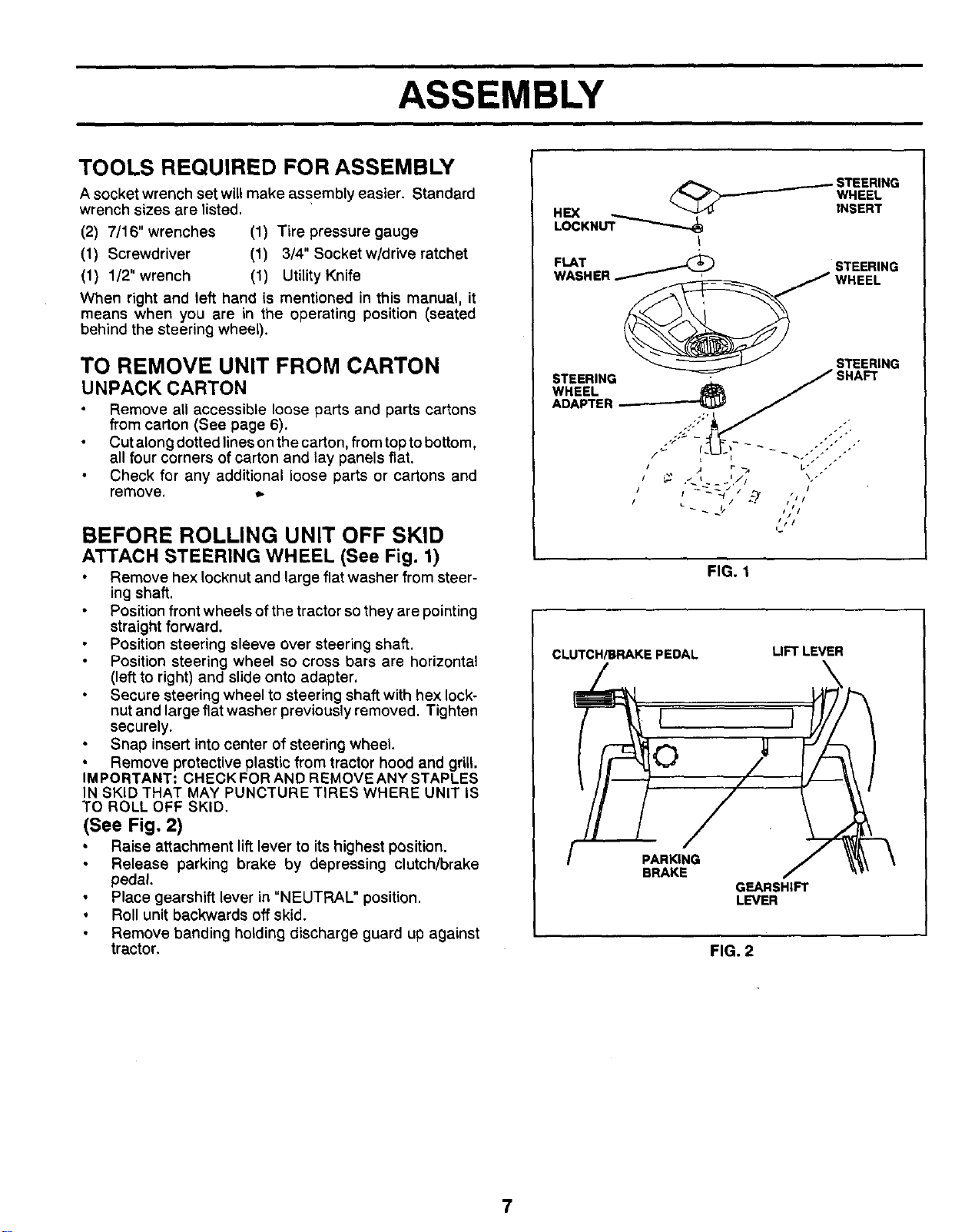
ASSEMBLY
TOOLS REQUIRED FOR ASSEMBLY
A socket wrench set will make assembly easier. Standard
wrench sizes are listed.
(2) 7/16" wrenches (1) Tire pressure gauge
(1) Screwdriver (1) 3/4" Socket w/drive ratchet
(1) 1/2" wrench (1) Utility Knife
When right and left hand is mentioned in this manual, it
means when you are in the operating position (seated
behind the steering wheel).
TO REMOVE UNIT FROM CARTON
UNPACK CARTON
Remove all accessible loose parts and parts cartons
from carton (See page 6).
Cut along dotted lines on the carton, from top to bottom,
all four corners of carton and lay panels fiat.
Check for any additional loose parts or cartons and
remove. ,_
BEFORE ROLLING UNIT OFF SKID
ATTACH STEERING WHEEL (See Fig. 1)
Remove hex Iocknut and large flat washer from steer-
ing shaft.
Positionfront wheels of the tractor sothey are pointing
straight forward.
Position steering sleeve over steering shaft,
Position steering wheel so cross bars are horizontal
(left to right) and slide onto adapter.
Secure steering wheel to steering shaft with hex lock-
nut and large flat washer previously removed, Tighten
securely.
Snap insert into center of steering wheel
• Remove protective plastic from tractor hood and grill.
IMPORTANT: CHECKFORAND REMOVEANY STAPLES
IN SKID THAT MAY PUNCTURE TIRES WHERE UNIT IS
TO ROLL OFF SKID,
(See Fig. 2)
° Raise attachment lift lever to its highest position.
Release parking brake by depressing clutch/brake
pedal.
Place gearshift lever in "NEUTRAL" position.
• Roll unit backwards off skid.
Remove banding holding discharge guard up against
tractor.
_ STEERING
WHEEL
HEX INSERT
LOCKNUT"_'_._._
FLAT _ STEERING
WASHER _-
STEERING
STEERING ,_ _ SHAFT
WHEEL _
ADAPTER_:
/ .j r _ t." .
/ • / ,
FIG. 1
CLUTCH/BRAKE PEDAL
UFTLEVER
PARKING
BRAKE
GEARSHIFT
LEVER
FIG. 2
7

ASSEMBLY
HOW TO SET UP YOUR TRACTOR
PREPARE BATTERY (See Fig, 3)
CAUTION: Wear eye and face shield.
Wash hands or clothing immediately if
accidentally in contact with battery acid.
Do not smoke. Fumes from charged bat-
tery acid are explosive.
Read the instructions included with the
battery vent caps• Always wear gloves,
clothing and goggles to protectyour hands,
skin and eyes.
Your unit has a battery charging system which issufficient
for normal use. However, periodic charging of the battery
with an automotive charger will extend its life.
See instructions packed with vent caps in parts bag.
Fill battery with acid. Fill each cell until it reaches the
bottom of the vent wells. Do not overfill.
Allow battery to stand and settle for at least thirty
minutes. After standing, check the level of acid. If
below the vent wells, add more acid until the correct
level is reached.
While battery isstanding (after adding acid) and later, while
battery is being charged, continue with assembly of unit.
IMPORTANT: TO MAXIMIZE THE LIFE OF YOUR
BATTERY, IT IS NECESSARY THAT THE BATTERY BE
CHARGED BEFORE USE. FAILURE TO CHARGE
BATTERY CAN RESULT IN A SHORTENED BATTERY
LIFE.
Charge battery at a rate of 6 amperes for 1 hour. Use
a 12 volt battery charger. Observe all safety precau-
tions required for battery charging.
Check the acid level after the battery is charged. If the
acid has fallen below the correct level, add distilled or
iron free water.
Install the vent caps to cover the vent wells. Wash the
top of the battery with water to remove any acid, then
wipe dry.
Check battery case for leakage to make sure that no
damage has occurred in handling.
Dispose of excess battery acid. Neutralize acid for
disposal by adding it to four inches of water in a five
gallon plastic container. Stir with a wooden or plastic
paddle while adding baking soda until the addition of
more soda causes no more foaming.
Follow instructions on how to install battery.
CUTAWAYVIEW j VENTCAP
I I- VENTwELL
_BATTERY
_ _ _., CELLACID
L=UIUL= '°v'"
INSTALL SEAT (See Fig. 4)
Adjust seat before tightening adjustment knob.
Remove cardboard packing on seat pan.
Place seat on pan and assemble shoulder bolt•
Assemble adjustment knob and flat washer loosely,
Do not tighten,
Tighten shoulder bolt securely.
Lower seat into operating position and sit on seat.
Slide seat untila comfortable position isreached which
allows you to press clutch/brake pedal all the way
down.
Get off seat without moving its adjusted position.
Raise seat and tighten adjustment knob securely.
SEAT
SEAT PAN
SHOULDER
ADJUSTMENT
KNOB
" FIG. 4
• CHECKTIRE PRESSURE
The tires on your unit were overinflated at the factory for
shipping purposes• Correct tire pressure is important for
best cutting performance,
Reduce tire pressure to PSI shown in "PRODUCT
SPECIFICATIONS" on page 3 of this manual.
CHECK DECK LEVELNESS
For best cutting results, mower housing should be properly
leveled. See "TO LEVEL MOWER HOUSING" in the
Service and Adjustments section of his manual.
CHECK FOR PROPER POSITION OF ALL
BELTS
See the figures that are shown for replacing motion, mower
drive, and mower blade drive belts in the Service and
Adjustments sectionofthis manual. Verify that the belts are
routed correctly.
FIG. 3
8

ASSEMBLY
CHECK BRAKESYSTEM
After you learn how to operate your tractor, check to see
that the brake is properly adjusted. See "TO ADJUST
BRAKE" in the Service and Adjustments section of this
manual.
INSTALL BATTERY (See Figs. 5 and 6)
&
CAUTION: Do not short battery terminals.
Before installing battery, remove metal
bracelets, wristwatch bands, rings, etc.
Positive terminal must be connected first
to prevent sparking from accidental
grounding.
Raise hood.
Make sure drain tube isfastened to drain hole inbattery
tray and battery tray,,is positioned in hole of battery
support.
Place battery in plastictray, battery terminals to frontof
tractor.
First connect RED battery cable to positive (+) battery
terminal with hex bolt, flat washer, lock washer and hex
nut as shown. Tighten securely.
Connect BLACK grounding cable to negative (-) battery
terminalwithremaining hex bolt,flatwasher, lockwasher
and hex nut. Tighten securely.
Slide the two battery bolts through the terminal guard
and start the wing nuts onto the threads.
Position terminal guard over the battery as shown, lower
bolts into key holes and slide square shaftsof bolts into
slots of key holes.
Tighten wing nuts by hand making sure battery bolts
remain in slots of the key holes in the battery support.
Be sure terminal access doors are closed.
Use terminal access doors for:
Inspection for secure connections (totighten hardware).
Inspection for corrosion.
Testing battery.
Jumping (if required).
• Periodic charging.
..,,,
HEX NUT
LOCK WAS
NEGATIVE"_::_i
(SLACK)
CABLE
POSITIVE
FLAT
WASHER
HEX
IOLT
FIG. 5
WING
NUTS
TERMINAL
GUARD
VENT .""
CAP
BATTERY :_
BOLT
ACCESS
"',.,,,
KEY HOLE
BATrERY
BAI"rERY
TRAY
-_
FIG, 6
9

ASSEMBLY
TO CONVERTTO BAGGING OR DISCHARGING
INSTALL MULCHER PLATE
(See Figs. 7 & 8)
Install two latch hook assemblies, to mulcher plate
using screw, washer, lock washer, and weld nut as
shown.
Tighten hardware securely.
Raise and hold deflector shield in upright position.
Place front of mulcher plate over front of mower deck
opening and slide into place, as shown.
Hook front latch into tab hole on front of mower deck.
Hook rear latch into tab hole on back of mower deck.
CAUTION: Do not remove discharge guard
from mower. Raise and hold guard when
attaching mulcher plate and allow it to
rest on plate while in operation,
MULCHER
WASHER
SCREW LATCH
_\ LOCKWASHER
_'_" J _WELD
LATCH -_J NUT
FIG. 7
DEFLECTOR
SHIELD
,,p
FIG, 8
LATCH
HOOKS
Simply remove mulcher plate and store in a safe place.
Your mower is now ready for discharging or installation of
optional grass catcher accessory.
/CHECKLIST
BEFORE YOU OPERATE AND ENJOY YOUR NEW
TRACTOR, WE WISH TOASSURE THAT YOU RECEIVE
THE BEST PERFORMANCEAND SATISFACTION FROM
THIS QUALITY PRODUCT.
PLEASE REVIEW THE FOLLOWING CHECKLIST:
,/ All assembly instructions have been completed.
,/ No remaining loose parts in carton.
,/ Battery is properly prepared and charged. (Minimum
1 hour at 6 amps).
,/ Seat is adjusted comfortably and tightened securely.
,/ All tires are properly inflated. (For shipping purposes,
the tires were over-inflated at the factory).
,/ Be sure mower deck is properly leveled side-to-side/
front-to-rear for best cutting results. (Tires must be
properly inflated for leveling).
,,t Check mower and drive belts. Be sure they are routed
properly around pulleys and inside all belt keepers.
,/ Check wiring. See that all connections are still secure
and wires are properly clamped.
WHILE LEARNING HOW TO USE YOUR TRACTOR, PAY
EXTRA ATTENTION TO THE FOLLOWlNG IMPORTANT
ITEMS:
/ Engine oil is_at proper level.
./ Fuel tank is filled with fresh, clean, regular unleaded
gasoline.
,/ Become familiar with all controls - their location and
function. Operate them before you start the engine.
,/ Be sure brake system is in safe operating condition.
10
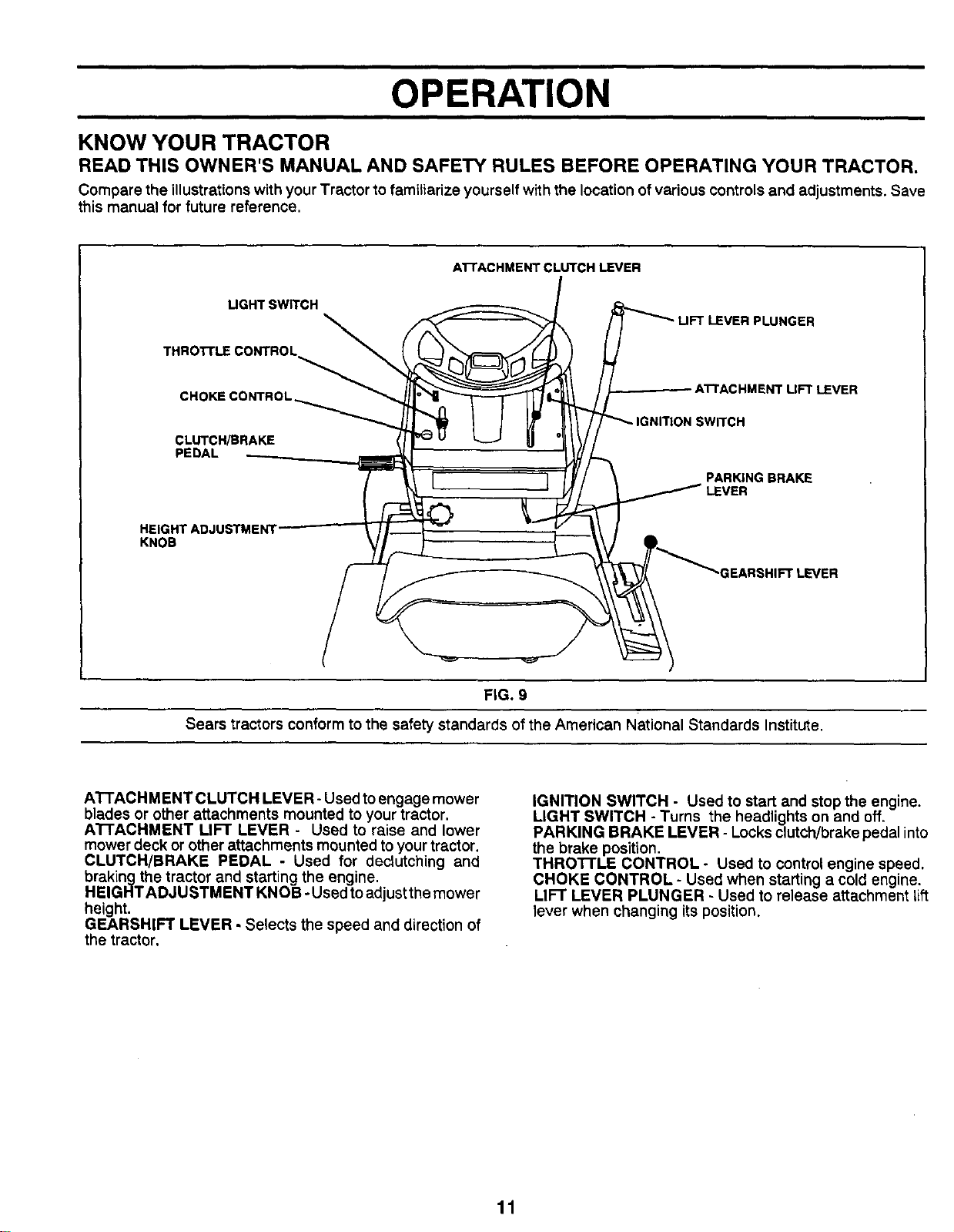
OPERATION
KNOW YOUR TRACTOR
READ THIS OWNER'S MANUAL AND SAFETY RULES BEFORE OPERATING YOUR TRACTOR.
Compare the illustrations with your Tractor to familiarize yourself with the location of various controls and adjustments. Save
this manual for future reference.
A'I-rACHMENT CLUTCH LEVER
UGHT SWITCH
THROTrLE CONTROL_
CHOKE CONTROL
CLUTCH/BRAKE
PEDAL
PLUNGER
T LIFT LEVER
SWITCH
PARKING BRAKE
KNOB
FIG. 9
Sears tractors conform to the safety standards of the American National Standards Institute.
ATTACH MENT CLUTCH LEVER - Used toengage mower
blades or other attachments mounted to your tractor.
A'I-rACHMENT LIFT LEVER - Used to raise and lower
mower deck or other attachments mounted to yourtractor.
CLUTCH/BRAKE PEDAL - Used for dectutching and
braking the tractor and starting the engine.
HEIGHTADJUSTMENT KNOB .iUsed toadjustthe mower
height.
GEARSHIFT LEVER - Selects the speed and direction of
the tractor,
IGNITION SWITCH - Used to start and stop the engine.
LIGHT SWITCH - Turns the headlights on and off.
PARKING BRAKE LEVER - Locks clutch/brake pedal into
the brake position.
THRO'n'LE CONTROL - Used to control engine speed.
CHOKE CONTROL - Used when starting a cold engine.
LIFT LEVER PLUNGER - Used to release attachment lift
lever when changing its position.
11
OPERATION
The operation of any tractor can result In foreign objects thrown Into the eyes, which can result
n severe eye damage. Always wear safety glasses or eye shields before starting your tractor
and while moving. We recommend Wide Vision Safety Mask for over the spectac es or standard
safety glasses.
HOW TO USE YOUR TRACTOR
TO SET PARKING BRAKE (See Fig, 10)
Depress clutch/brake pedal intofull "BRAKE" position
and hold.
Place parking brake lever in "ENGAGED" position and
release pressure from clutch/brake pedal. Pedal should
remain in "BRAKE" position. Make sure parking brake
will hold vehicle secure.
STOPPING (See Fig. 10)
MOWER BLADES -
Move attachment clutch lever to "DISENGAGED" po-
sition.
GROUND DRIVE -
Ib
Depress clutch/brake pedal into full "BRAKE" position.
Move gearshift lever to "NEUTRAL" position.
ENGINE -
Move Throttle Control to "SLOW" position.
Turn ignition key to "OFF" position and remove key.
Always remove key when leaving vehicle to prevent
unauthorized use.
Never use choke to stop engine.
NOTE: Under certain conditions when unit is standing idle
with the engine running, hot engine exhaust gasses may
cause "browning" of grass. To eliminate this possibility,
always stop engine when stopping unit on grass areas.
CAUTION: Always stop unit completely, as
described above, before leaving the
operator's position; to empty grass catcher,
etc.
f
I
TO USE CHOKE CONTROL (See Fig. 10)
Use choke controlwhenever you are starting a cold engine.
Do not use to start a warm engine.
To engage choke control, pull knob out. Slowly push
knob in to disengage.
TO USE THROI-rLE CONTROL (See Fig. 10)
Always operate engine at full throttle.
Operating engine at less than full throttle reduces the
battery charging rate and the engine cooling air flow.
Full throttle offers the best mower performance.
TO MOVE FORWARD AND BACKWARD
(See Fig. 10)
The direction and speed of movement iscontrolled by the
gearshift lever,
Start tractor with clutch/brake pedal depressed and
gearshift lever in =NEUTRAL" position.
12
Move gearshift lever to desired position.
Slowly release clutch/brake pedal to start movement.
IMPORTANT: BRING TRACTOR TO A COMPLETE STOP
BEFORE SHIFTING OR CHANGING GEARS. FAILURE
TO DO SO WILL SHORTEN THE USEFUL LIFE OF YOUR
TRANSAXLE.
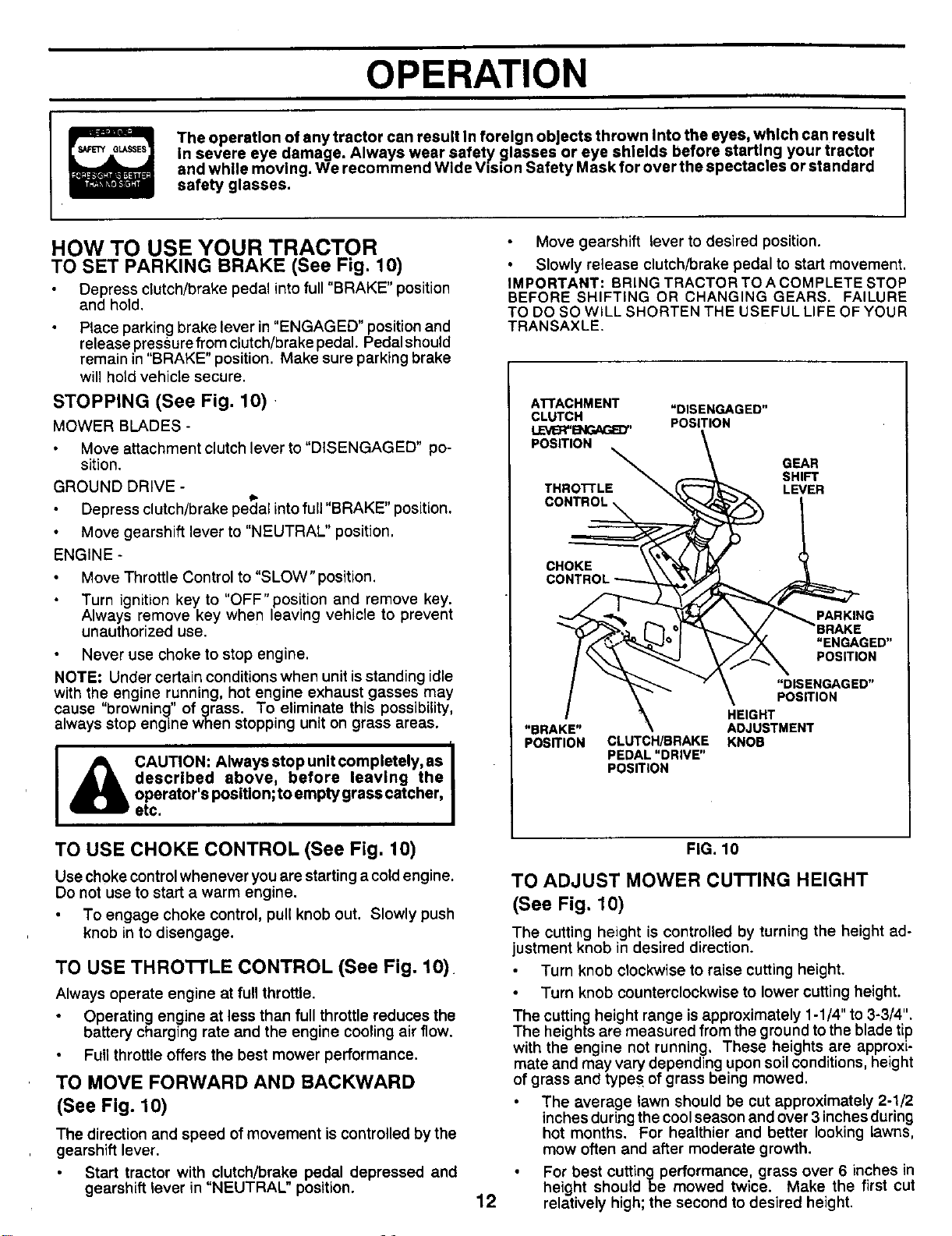
ATTACHMENT "DISENGAGED"
CLUTCH POSITION
LEVB_'IE_GAP.-_Y'
POSITION
E_ GEAR
SHIFT
THRO'I-rL LEVER
CHOKE
"BRAKE"
POSITION
CLUTCH_RAKE
PEDAL"DRIVE"
POSITION
PARKING
"ENGAGED"
POSITION
"DISENGAGED"
POSITION
HEIGHT
ADJUSTMENT
KNOB
FIG. 10
TO ADJUST MOWER CUTTING HEIGHT
(See Fig. 10)
The cutting height is controlled by turning the height ad-
justment knob in desired direction.
Turn knob clockwise to raise cutting height.
Turn knob counterclockwise to lower cutting height.
The cutting height range is approximately 1-1/4" to 3-3/4".
The heights are measured from the ground to the blade tip
with the engine not running, These heights are approxi-
mate and may vary depending upon soil conditions, height
of grass and types of grass being mowed.
The average lawn should be cut approximately 2-1/2
inches during the cool season and over 3 inches during
hot months. For healthier and better looking lawns.
mow often and after moderate growth.
For best cutting performance, grass over 6 inches in
height should be mowed twice. Make the first cut
relatively high; the second to desired height.
i
OPERATION
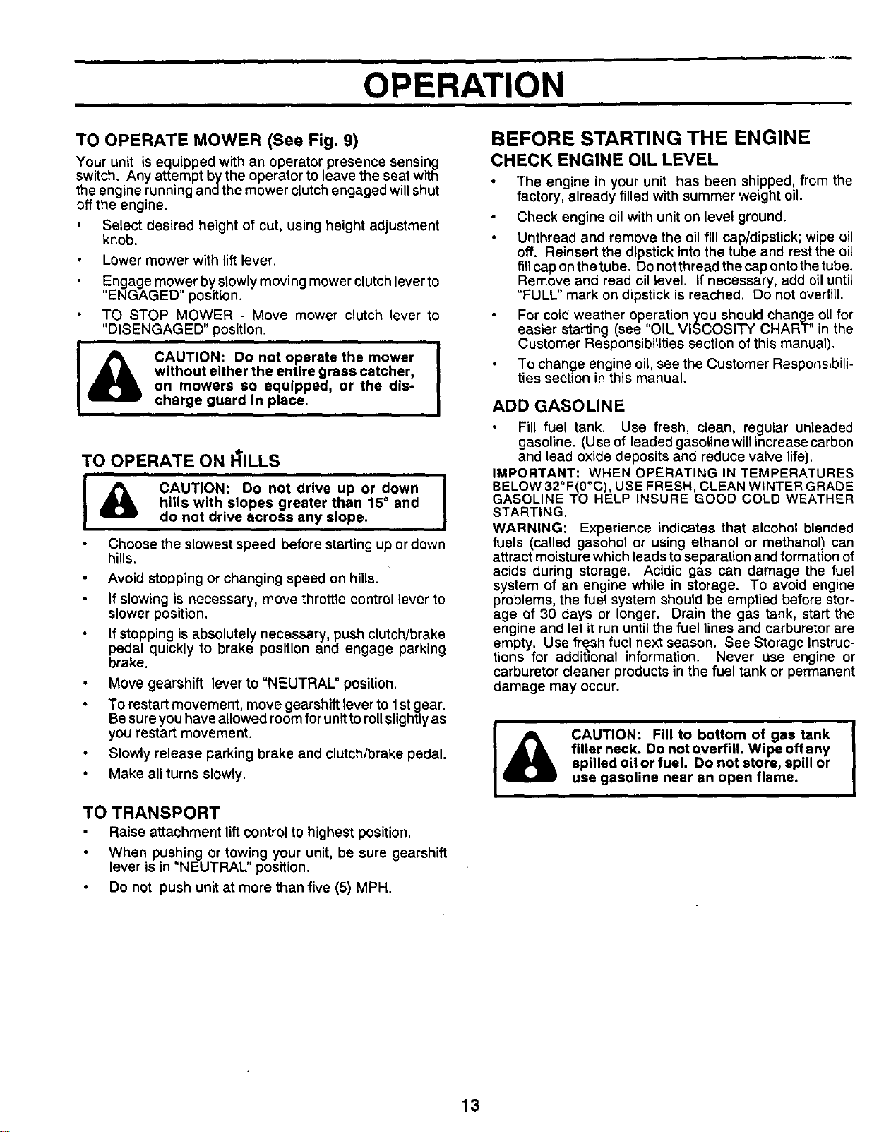
TO OPERATE MOWER (See Fig. 9)
Your unit is equipped with an operator presence sensing
switch, Any attempt by the operator to leave the seat with
the engine running andthe mower clutchengaged willshut
offthe engine.
Select desired height of cut, using height adjustment
knob.
Lower mower with lift lever.
I
Engage mower by slowly moving mower clutch lever to
"ENGAGED" position.
TO STOP MOWER - Move mower clutch lever to
"DISENGAGED" position.
&
I
CAUTION: Do not operate the mower I
without either the entire grass catcher,
I
on mowers so equipped, or the dis-
charge guard in place.
TO OPERATE ON _ILLS
I & CAUTION: Do not drive up or down I
hills with slopes greater than 15° and
do not drive across any slope.
Choose the slowest speed before starting up ordown
hills.
Avoid stopping or changing speed on hills.
If slowing is necessary, move throttle control lever to
slower position.
If stopping is absolutely necessary, push clutch/brake
pedal quickly to brake position and engage parking
brake.
Move gearshift lever to "NEUTRAL" position.
To restart movement, move gearshift lever to 1st gear.
Be sure you have allowed room for unitto roll slightly as
you restart movement.
Slowly release parking brake and clutch/brake pedal.
Make all turns slowly.
TO TRANSPORT
Raise attachment lift control to highest position.
When pushing or towing your unit, be sure gearshift
lever is in "NEUTRAL" position.
Do not push unit at more than five (5) MPH.
BEFORE STARTING THE ENGINE
CHECK ENGINE OIL LEVEL
The engine in your unit has been shipped, from the
factory, already filled with summer weight oil.
Check engine oil with unit on level ground.
Unthread and remove the oil fill cap/dipstick; wipe oil
off. Reinsert the dipstick into the tube and rest the oil
fill cap on the tube. Do not thread the cap onto the tube.
Remove and read oil level. If necessary, add oil until
"FULL" mark on dipstick is reached. Do not overfill.
For cotd weather operation you should change oil for
easier starting (see "OIL VISCOSITY CHART" in the
Customer Responsibilities section of this manual).
To change engine oil, see the Customer Responsibili-
ties section in this manual.
ADD GASOLINE
Fill fuel tank. Use fresh, clean, regular unleaded
gasoline. (Use of leaded gasolinewill increase carbon
and lead oxide deposits and reduce valve life).
IMPORTANT: WHEN OPERATING IN TEMPERATURES
BELOW 32°F(0°C), USE FRESH, CLEAN WINTER GRADE
GASOLINE TO HELP INSURE GOOD COLD WEATHER
STARTING.
WARNING: Experience indicates that alcohol blended
fuels (caUed gasohol or using ethanol or methanol) can
attract moisture which leads to separation and formation of
acids during storage. Acidic gas can damage the fuel
system of an engine while in storage. To avoid engine
problems, the fuel system should be emptied before stor-
age of 30 days or longer. Drain the gas tank, start the
engine and let it run untilthe fuel lines and carburetor are
empty. Use fresh fuel next season. See Storage Instruc-
tions for additional information. Never use engine or
carburetor cleaner products in the fuel tank or permanent
damage may occur.
I& CAUTION: Fill to bottom of gas tank I
|
filler neck. Do not overfill. Wipe off any
spilled oil or fuel. Do not store, spill or
use gasoline near an open flame.
13

OPERATION
TO START ENGINE (See Fig. 10)
When starting engine for the first time or if engine has
run out of fuel, it will take extra cranking time to move
fuel from the tank to the engine.
Depress the clutch/brake pedal and set the parking
brake•
Place gearshift lever in "NEUTRAL" position.
Move attachment clutch to "DISENGAGED" position.
Pull choke control out to "CHOKE" position for cold
engine start. For warm engine start do not use
choke control.
Move throttle control to midway between "FAST" and
"SLOW" positions.
Turn ignition key clockwise to "START" position and
release key as soon as engine starts. Do not run
starter continuously for more than fifteen seconds
per minute. If engine does not start after several
attempts, move throttle control to "FAST" position,
wait a few minutes and try again.
When engine starts, slowly push choke control in.
Move throttle control to "FAST" position.
• tt.
Allow engine to warm up for a few minutes before
engaging clutch/brake pedal or attachment clutch
lever.
NOTE: If at a high altitude (above 3000 feet) or in cold
temperatures (below 32 ° F), the carburetor fuel mixture
may need to be adjusted for best engine performance.
See "TO ADJUST CARBURETOR" in the Service and
Adjustments section of this manual.
MOWING TIPS
Tire chains cannot be used when the mower housing
is attached to unit.
Mower should be properly leveled for best mowing
performance. See "TO LEVEL MOWER HOUSING"
in the Service and Adjustments section of this
manual.
The left hand side of mower should be used for trim-
ming.
Drive so that clippings are discharged onto the area
that has been cut. Have the cut area to the right of
the machine. This will result in a more even distri-
bution of clippings and more uniform cutting.
When mowing large areas, start by turning to the
right so that clippings will discharge away from
shrubs, fences, driveways, etc. After one or two
rounds, mow in the opposite direction making left
hand turns until finished(See Fig. 11).
f
1
t
r D
(
|
I
I
J
FIG. 11
14
If grass is extremely tall, it should be mowed twice
to reduce load and possible fire hazard from dried
clippings. Make first cut relatively high; the second
to the desired height.
Do not mow grass when it is wet. Wet grass will
plug mower and leave undesirable clumps. Allow
grass to dry before mowing.
Always operate engine at full throttle when mowing
to assure better mowing performance and proper
discharge of material. Regulate ground speed by
selecting a low enough gear to give the mower cut-
ting performance as well as the quality of cut de-
sired.
When operating attachments, select a ground speed
that will suit the terrain and give best performance of
the attachment being used.
MULCHING MOWING TIPS
IMPORTANT; FOR BEST PERFORMANCE, KEEP
MOWER HOUSING FREE OF BUILT-UP GRASS AND
TRASH. CLEAN AFTER EACH USE.
• The special mulching blade will recut the grass clip-
pings many times and reduce them in size so that as
they fall onto the lawn they will disperse intothe grass
and not be noticed. Also, the mulched grass will
biodegrade quickly to provide nutrients for the lawn.
Always mulch with your highest engine (blade) speed
as this will provide the best recutting action of the
blades.
Avoid cutting your lawn when it is wet. Wet grass
tends to form clumps and interferes with the mulching
action. The best time to mow your lawn is the early
afternoon. At this time the grass has dried and the
newly cut are_. will not be exposed to the direct sun.
For best results, adjust the mower cutting height so
that the mower cuts off only the top one-third of the
grass blades (See Fig. 12). For extremely heavy
mulching, reduce your width of cut and mow slowly.
MAX1/3
FIG. 12
Certain types of grass and grass conditions may
require that an area be mulched a second time to
completely hide the clippings. When doing a second
cut, mow across or perpendicular to the first cutpath.
Change your cutting pattern from week to week. Mow
north to south one week then change to east to west
the next week, This will help prevent matting and
graining of the lawn.

CUSTOMER RESPONSIBILITIES
AS YOU COMPLETE
.E O RSERV,CE oATEs
Check Brake Operation _
Check Tire Pressure
T Check for Loose Fasteners _ if
Sharpen/Replace Mower Blades _4
A Lubricati°n Chart _
T Check Battery Level/Recharge
Clean Battery and Terminals if
R Check Transmission Cooling
v'
Adjust Blade Belt(s) Tension
Adjust Motion Drive Belt(s) Tension
Check Engine Oil Level _// _1
Change Engine Oil I _ Ik_.2._ _44
Clean Air Filter _'2
i E clean Air screen _/2
G Inspect Muffler/Spark Arrester I_
I Replace Oil Filter (If equipped) 1_.2
I N Clean Engine Cooling Fins ip#'2
im
Replace Spark Plug _ V _
Replace Air Filter Paper Cartridge
V'2
Replace Fuel Filter _1'
1 - Change more oftenwhen operatingunder a heavy load orin highambienttemperatures.
2 - Service more oftenwhen operating indirty or dusty conditions,
3 - Ifequipped withoilfilter, changeollever,/50 hours,
4 - Replace blades more oftenwhen mowing insandy soil
GENERAL RECOMMENDATIONS
The warranty on this vehicle does not cover itemsthat have
been subjected to operator abuse or negligence. To
receive full value from the warranty, operator must main-
tain unit as instructed in this manual.
Some adjustments will need to be made periodically to
properly maintain your unit.
All adjustments in the Service and Adjustments section of
this manual should be checked at least once each season.
LUBRICATION CHART
(If equipped) (if equipped)
®
- FRONTWHEEL _)
BEARING ZERK BEARING ZERK
Once a year you should replace the spark plug, clean
or replace air filter, and check blades and belts for
wear. A new spark plug and clean air filter assure (_
proper air-fuel mixture and help your engine run better CLUTCH
and last longer. PIVOT(S)
BEFORE EACH USE
Check engine oil level.
Check brake operation.
Check tire pressure.
Check for loose fasteners.
®
PIVOTS
15
(_SAE 30 MOTOR OIL API - BG
{_)GENERAL PURPOSE GREASE
_) REFER TO CUSTOMER RESPONSIBIUTIES "ENGINE" SECTION
IMPORTANT: DO NOT OIL OR GREASE THE PIVOT POINTS
WHICH HAVE SPECIAL NYLON BEARINGS. VISCOUS LUBRI-
CANTS WILL ATTRACT DUST AND DIRT THAT WILL SHORTEN
THE LIFE OF THE SELF-LUBRICATING BEARINGS. IF YOU
FEEL THEY MUST BE LUBRICATED, USE ONLY A DRY, POW-
DERED GPAPHITE TYPE LUBRICANT SPARINGLY.

CUSTOMER RESPONSIBILITIES
TRACTOR
Always observe safety rules when performing any mainte-
nance.
BRAKE OPERATION
If unit requires more than six (6) feet stopping distance at
high speed in highest gear, than brake must be adjusted.
(See "TO ADJUST BRAKE" in Service and Adjustments
section of this manual).
TIRES
Maintain proper air pressure in all tires (See "PROD-
UCT SPECIFICATIONS" on page 3 of this manual).
Keep tires free of gasoline, oil, or insect control chemi-
cals which can harm rubber.
Avoid stumps, stones, deep ruts, sharp objects and
other hazards that may cause tire damage.
BLADE CARE
For best results mower bla_les must be kept sharp. The
blades can be sharpened with a file or on a grinding wheel,
We suggest they be sharpened or replaced after every 25
hours of mowing, Check blades more often if mowing in
sandy conditions,
Do notattempt to sharpen btades while they are on the
mower.
Replace bent or damaged blades.
BLADE REMOVAL (See Fig. 13)
Raise mower to highest position to allow access to
blades.
Remove hex bolt, lock washer and flatwasher securing
blade.
Install new or resharpened blade with trailing edge up
towards deck as shown.
Reassemble hex bolt, lock washer and flat washer in
exact order as shown.
Tighten bolt securely (30-35 Ft. Lbs. torque).
IMPORTANT: BLADE BOLT IS GRADE 8 HEAT TREATED.
\ ""''Y
LOCKWAS.ER---'--4.
BOLT(G'=DE,)"
*A GRADE 8 HEAT TREATED BOLT CAN BE
IDENTIFIED BY SiX LINES ON THE BOLT HEAD,
FIG, 13
TO SHARPEN BLADE (See Fig. 14)
Care should be taken to keep the blade balanced. An
unbalanced blade willcause excessive vibration and even-
_tual damage to mower and engine.
The blade can be sharpened with a file or on a grinding
wheel. Do not attempt tosharpen while on the mower.
To check blade balance, you will need a 5/8" diameter
steel bolt, pin, or a cone batancer. (When using a cone
balancer, follow the instructions supplied with bal-
ancer).
Slide blade on to an unthreaded portion ofthe steelbolt
or pin and hold the bolt or pin parallel with the ground.
If blade is balanced, it should remain in a horizontal
position. If either end of the blade moves downward,
sharpen the heavy end until the blade is balanced.
NOTE: Do not use a nail for balancing blade. The lobes of
the center hole may appear to be centered, but are not.
CENTER HOLE / /
FIG. 14
16

CUSTOMER RESPONSIBILITIES
BATTERY (See Fig. 15) ENGINE
LUBRICATION
Your unithas a battery charging system which is sufficient
for normal use. However, periodic charging of the battery
with an automotive charger will extend it's life.
Acid solution level in each battery cell should be even
with bottomsofventwells. Add onlydistilledor ironfree
water if necessary. Do not overfill.
CUT AWAY VIEW
WELL
CELL ACID
LEVEL
FIG. 15
Keep battery and terminals clean.
Keep battery bolts tight.
Keep vent capstight and small ventholes in capsopen.
Recharge at 6 amperes for 1 hour.
TO CLEAN BATTERY AND TERMINALS -
Corrosion and dirton the battery and terminals can cause
the battery to "leak" power.
Remove terminal guard.
Disconnect BLACK battery cable first then RED bat-
tery cable and remove battery from tractor.
Wash battery with solution of four tablespoons of
baking sodato one gallon ofwater. Be careful notto get
the soda solution intothe ceils.
Rinse the battery with plain water and dry.
Clean terminals and battery cable ends with wire brush
until bright.
Coat terminals with grease or petroleum jelly.
Reinstall battery (See "INSTALL BATTERY" in the
Assembly section of this manual).
V-BELTS
Check V-belts for deterioration and wear after 100 hours
and replace if necessary. The belts are not adjustable.
Replace belts if they begin to slip from wear.
Only use high quality detergent oil rated with API service
classification SG. Select the oil's SAE viscosity grade
according to your expected operating temperature.
RECOMMENDED SAE VISCOSITY GRADES
°F -20° 0° 32° 60° 80° 100°
=C -29° -18 ° 0° 16° 27° 38°
NOTE: Although multi-viscosity oils (5W30, 10W30 etc.)
improve starting in cold weather, these multi-viscosity oils
will result in increased oil consumption when used above
32°F, Check your engine oil level more frequently to avoid
possible engine damage from running low on oil.
Change the oil after the first two hours of operation and
every 50 hours thereafter or at least once a year if the
tractor is not used for 50 hours in one year.
Check the crankcase oil level before starting the engine
and after each eight (5) hours of continuous use. Tighten
oil fill cap/dipstick securely each time you check the oil
level.
TO CHANGE ENGINE OIL
Be sure vehicle is on level surface.
Oil will drain more freely when warm.
Catch oil in a suitable container.
Remove oil fill dipstick. Be careful not to allow dirt to
enter the engine when changing oil.
Remove d_ain plug.
After oil has drained completely, replace oil drain plug
and tighten securely.
Refill engine with oil through oil fill dipstick tube, Pour
slowly. Do not overfill. For approximate capacity see
Product Specifications on page 3 of this manual
Use gauge on oil fill dipstick for checking level. Do not
thread the cap onto the tube when taking reading.
Keep oilat"FU LL"line on dipstick. Tighten cap onto the
tube securely when finished.
TRANSAXLE COOLING
Keep transaxle free from build-up of dirt and chaff which
can restrict cooling,
17
CUSTOMER RESPONSIBILITIES
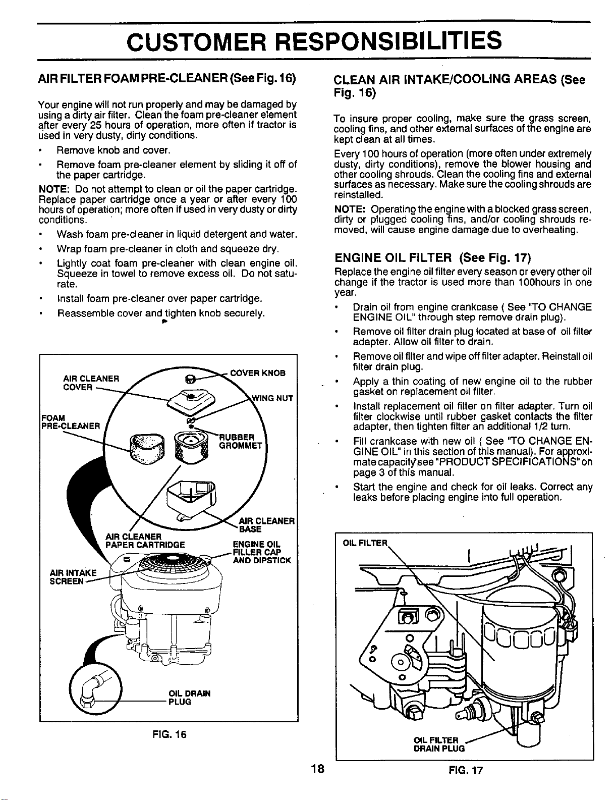
AIR FILTER FOAM PRE-CLEANER (See Fig, 16) CLEAN AIR INTAKE/COOLING AREAS (See
Fig. 16)
Your engine will not run properly and may be damaged by
using a dirty air filter. Clean the foam pre-claaner element
after every 25 hours of operation, more often if tractor is
used in very dusty, dirty conditions.
Remove knob and cover.
Remove foam pre-cleaner element by sliding it off of
the paper cartridge.
NOTE: Do not attempt to clean or oil the paper cartridge.
Replace paper cartridge once a year or after every 100
hours of operation; more often if used in very dusty or dirty
conditions.
Wash foam pre-cleaner in liquid detergent and water.
Wrap foam pre-cleaner in cloth and squeeze dry.
Lightly coat foam pre-cleaner with clean engine oil.
Squeeze in towel to remove excess oil. Do not satu-
rate.
Install foam pre-cleaner over paper cartridge.
Reassemble cover and tighten knob securely.
Ib
AIR CLEANER
COVER
.COVER KNOB
FOAM
PRE-CLEANER
AIRINTAKE
AIR CLEANER
PAPER CARTRIDGE
CLEANER
BASE
ENGINE OIL
CAP
AND DIPSTICK
OIL DRAIN
PLUG
FIG. 16
To insure proper cooling, make sure the grass screen,
cooling fins, and other external surfaces of the engine are
kept clean at all times.
Every 1O0 hours of operation (more often under extremely
dusty, dirty conditions), remove the blower housing and
other cooling shrouds. Clean the cooling fins and external
surfaces as necessary. Make sure the cooling shrouds are
reinstalled.
NOTE: Operating the engine with a blocked grass screen,
dirty or plugged cooling fins, and/or cooling shrouds re-
moved, will cause engine damage due to overheating.
ENGINE OIL FILTER (See Fig. 17)
Replace the engine oilfilter every season or every other oil
change if the tractor is used more than 100hours in one
year.
Drain oil from engine crankcase ( See "TO CHANGE
ENGINE OIL" through step remove drain plug).
Remove oilfilter drain plug located at base of oil filter
adapter. Allow oil filter to drain.
Remove oilfilter and wipe offfilter adapter. Reinstall oil
filter drain plug.
Apply a thin coating of new engine oil to the rubber
gasket on replacement oil filter.
Install replacement oil filter on filter adapter. Turn oil
filter clockwise until rubber gasket contacts the filter
adapter, then tighten filter an additional 1/2 turn.
Fill crankcase with new oil ( See "TO CHANGE EN-
GINE OIL" in this section ofthis manual). For approxi-
mate capacit_see "PRODUCT SPECIFICATIONS" on
page 3 of this manual.
Start the engine and check for oil leaks. Correct any
leaks before placing engine into full operation.
OIL FILTER [ . ,, tLt....._."
18 FIG. 17
CUSTOMER RESPONSIBILITIES
CLEANING
MUFFLER
Inspect and replace corroded muffler and spark arrester (if
equipped) as it could create a fire hazard and/or damage.
SPARK PLUGS
Replace spark plugs at the beginning of each mowing
season or after every 100 hours of use, whichever comes
first. Spark plug type and gap setting isshown in "PROD-
UCT SPECIFICATIONS on page 3 of this manual.
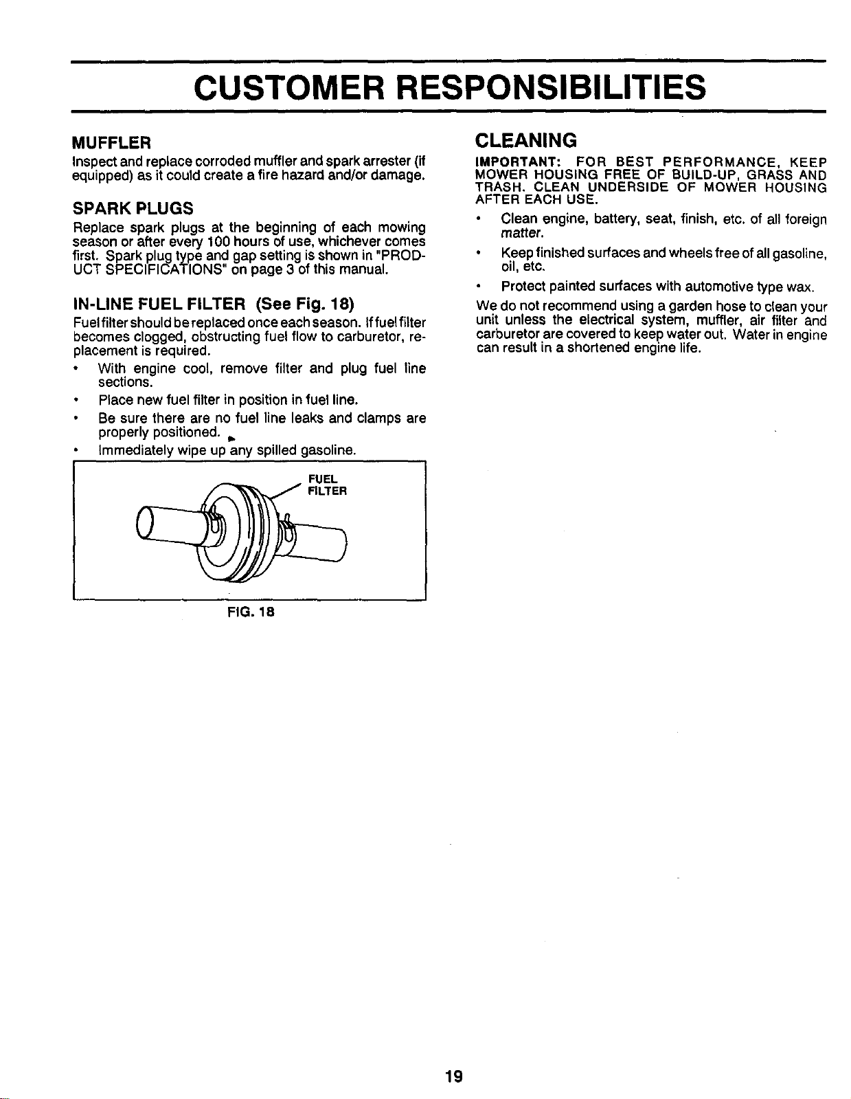
IN-LINE FUEL FILTER (See Fig. 18)
Fuelfiltershould be replaced once each season. Iffuelfiiter
becomes clogged, obstructing fuel flow to carburetor, re-
placement is required.
With engine cool, remove filter and plug fuel line
sections.
Place new fuel filter in position in fuel line.
Be sure there are no fuel line leaks and clamps are
properly positioned, j.
Immediately wipe up any spilled gasoline.
UEL
IMPORTANT: FOR BEST PERFORMANCE, KEEP
MOWER HOUSING FREE OF BUILD-UP, GRASS AND
TRASH. CLEAN UNDERSIDE OF MOWER HOUSING
AFTER EACH USI=.
Clean engine, battery, seat, finish, etc. of all foreign
matter.
Keep finished surfaces and wheels free of all gasoline,
oil, etc,
Protect painted surfaces with automotive type wax.
We do not recommend using a garden hose to clean your
unit unless the electrical system, muffler, air filter and
carburetor are covered to keep water out. Water in engine
can result in a shortened engine life.
FIG. 18
19
SERVICE AND ADJUSTMENTS
TRACTOR
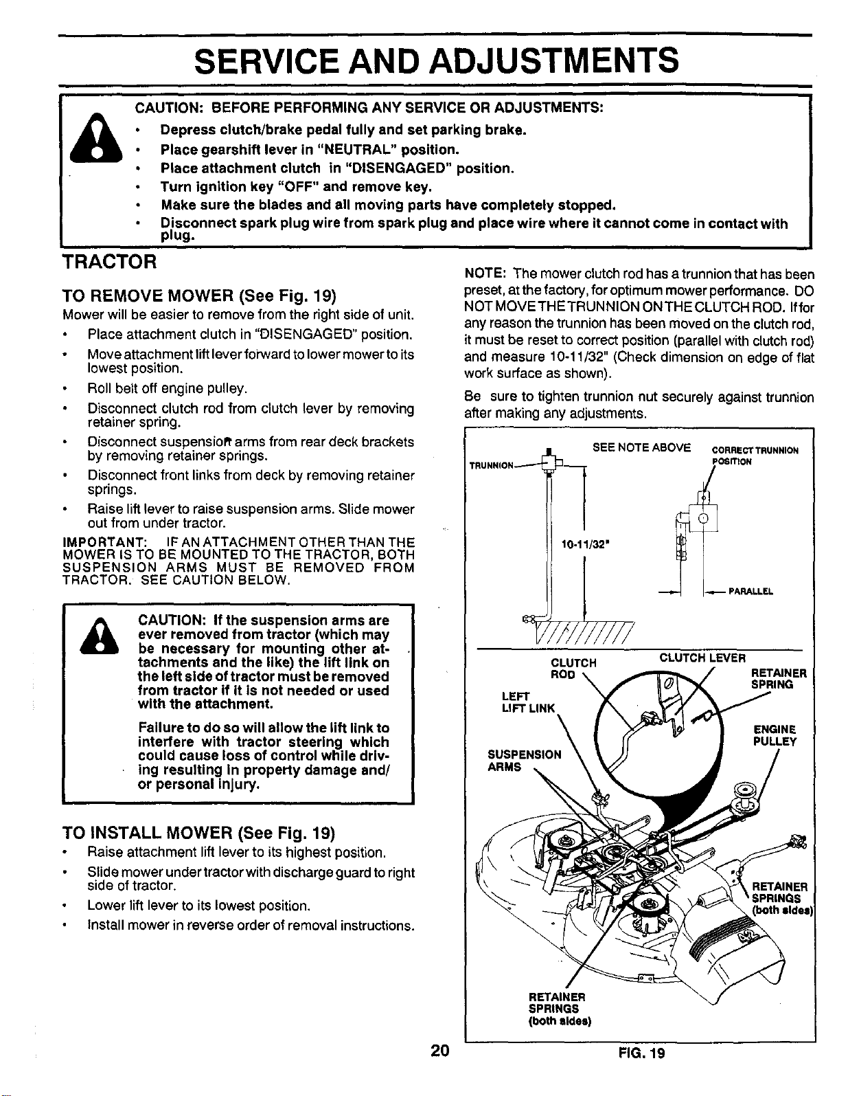
TO REMOVE MOWER (See Fig. 19)
Mower will be easier to remove from the right side of unit.
Place attachment clutch in "DISENGAGED" position.
Move attachment liftlever forward to lower mower to its
lowest position.
Roll belt off engine pulley.
Disconnect clutch rod from clutch lever by removing
retainer spring.
Disconnect suspensioR' arms from rear deck brackets
by removing retainer springs.
Disconnect front links from deck by removing retainer
springs.
Raise lift lever to raise suspension arms. Slide mower
out from under tractor.
IMPORTANT: IF AN ATTACHMENT OTHER THAN THE
MOWER IS TO BE MOUNTED TO THE TRACTOR, BOTH
SUSPENSION ARMS MUST BE REMOVED FROM
TRACTOR. SEE CAUTION BELOW.
A
CAUTION: If the suspension arms are
ever removed from tractor (which may
be necessary for mounting other at-
tachments and the like) the lift link on
the left side of tractor must be removed
from tractor if It Is not needed or used
with the attachment.
Failure to do so will allow the lift link to
interfere with tractor steering which
could cause loss of control while driv-
ing resulting In property damage and/
or personal injury.
TO INSTALL MOWER (See Fig. 19)
Raise attachment lift lever to its highest position.
Slide mower under tractorwith discharge guard toright
side of tractor.
Lower lift lever to itslowest position,
Install mower in reverse order of removal instructions.
NOTE: The mower clutch rod has a trunnion that has been
preset, atthe factory, for optimum mower performance. DO
NOT MOVETHETRUNNION ONTHE CLUTCH ROD. Iffor
any reason the trunnion has been moved on the clutchrod,
itmust be reset to correctposition (parallel with clutchrod)
and measure 10-11/32" (Check dimension on edge offlat
work surface as shown).
Be sure to tighten trunnion nut securely against trunnion
after making any adjustments.
TRUNNION .._ "-J
SEE NOTE ABOVE
3
10-11]32" I
9///////
CLUTCH
ROD
LEFT
LIFT LINK
CORRECT TRUNNION
POSITION
PARALLEL
CLUTCH LEVER
RETAINER
SPRING
ENGINE
PULLEY
SUSPENSION
ARMS
RETAINER
(both sldel
RETAINER
SPRINGS
(both sides)
20 FIG. 19
i i
SERVICE AND ADJUSTMENTS
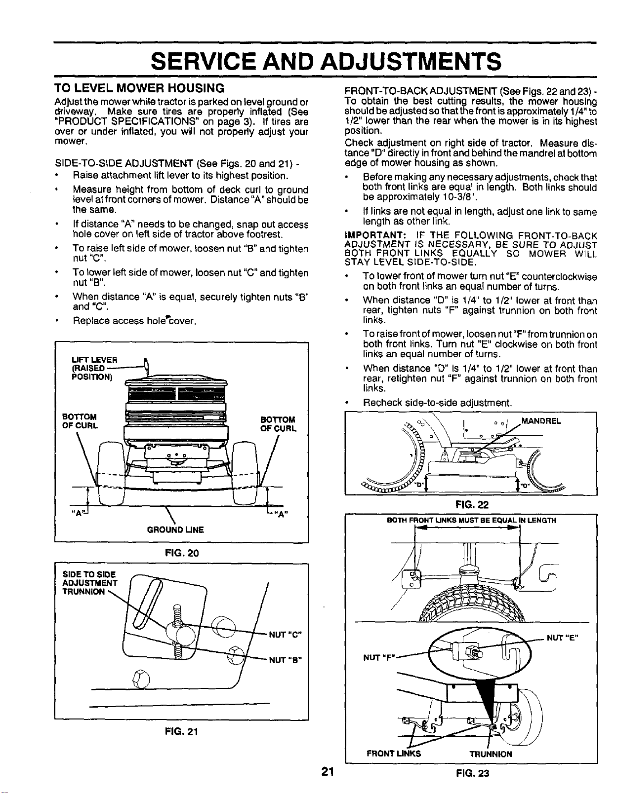
TO LEVEL MOWER HOUSING
Adjustthe mower while tractor is parked on level ground or
driveway. Make sure tires are properly inflated (See
"PRODUCT SPECIFICATIONS" on page 3). If tires are
over or under inflated, you will not properly adjust your
mower.
SIDE-TO-SIDE ADJUSTMENT (See Figs. 20 and 21) -
Raise attachment lift lever to its highest position.
Measure height from bottom of deck curl to ground
level at front corners of mower. Distance' A" should be
the same.
If distance "A" needs to be changed, snap out access
hole cover on left side of tractor above footrest.
To raise left side of mower, loosen nut "B" and tighten
nut "C".
To lower left side of mower, loosen nut "C" and tighten
nut "B".
When distance "A" is equal, securely tighten nuts "B"
and "C".
Replace access hole_cover.
LIFT LEVER
(RAISED
POSITION)
BOTTOM BOTTOM
OF CURL OF CURL
\
GROUNDLINE
FIG. 20
SIDE TO SIDE
ADJUSTMENT
TRUNNION
NUT "C"
NUT "B"
FIG. 21
FRONT-TO-BACK ADJUSTMENT (See Figs. 22 and 23) -
To obtain the best cutting results, the mower housing
should be adjusted sothat thefront isapproximately 1/4"to
1/2" lower than the rear when the mower is in its highest
position.
Check adjustment on right side of tractor. Measure dis-
tance "D" directly infront and behind the mandrel at bottom
edge of mower housing as shown.
Before making any necessary adjustments, check that
both front links are equal in length. Both linksshould
be approximately 10-3/8".
If links are not equal in length, adjust one link tosame
length as other link.
IMPORTANT: IF THE FOLLOWING FRONT-TO-BACK
ADJUSTMENT IS NECESSARY, BE SURE TO ADJUST
BOTH FRONT LINKS EQUALLY SO MOWER WILL
STAY LEVEL SIDE-TO-SIDE.
To lower front of mower turn nut "E" counterclockwise
on both front links an equal number of turns.
When distance "D" is 1/4" to 1/2" lower at front than
rear, tighten nuts "F" against trunnion on both front
links.
To raise front of mower, loosen nut "F" from trunnionon
both front links. Turn nut "E" clockwise on both front
links an equal number of turns.
When distance "D" is 1/4" to 1/2" lower at front than
rear, retighten nut "F" against trunnion on both front
links.
Recheck side-to-side adjustment.
MANDREL
FIG. 22
BOTH FRONT LINKS MUST BEEQUAL IN LENGTH
NUT "E"
FRONT LINKS TRUNNION
21 FIG. 23
SERVICE AND ADJUSTMENTS
WITHPARKINGBRAKE"ENGAGED"
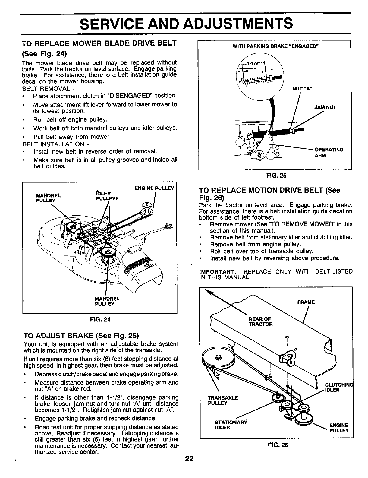
TO REPLACE MOWER BLADE DRIVE BELT
(See Fig. 24)
The mower blade drive belt may be replaced without
tools. Park the tractor on level surface. Engage parking
brake. For assistance, there is a belt installation guide
decal on the mower housing.
BELT REMOVAL -
Place attachment clutch in "DISENGAGED" position.
Move attachment lift lever forward to lower mower to
its lowest position.
Roll belt off engine pulley.
Work belt oft both mandrel pulleys and idler pulleys.
Pull belt away from mower.
BELT INSTALLATION -
Install new belt in reverse.order of removal,
Make sure belt is in all pulley grooves and inside all
belt guides.
MANDREL
PULLEY
_)LER
PULLEYS
ENGINE PULLEY
MANDREL
PULLEY
NUT"A"
JAM NUT
OPERATING
ARM
FIG. 25
TO REPLACE MOTION DRIVE BELT (See
Fig. 26)
Park the tractor on level area. Engage parking brake.
For assistance, there is a belt installation guide decal on
bottom side of left footrest.
Remove mower (See "TO REMOVE MOWER" in this
section of this manual).
Remove belt from stationary idler and clutching idler,
Remove belt from engine pulley.
Roll belt over top of transaxle pulley.
Install new belt by reversing above procedure.
IMPORTANT: REPLACE ONLY WITH BELT LISTED
IN THIS MANUAL
FRAME
FIG, 24
TO ADJUST BRAKE (See Fig. 25)
Your unit is equipped with an adjustable brake system
which is mounted on the right side of the transaxle.
If unit requires more than six (6) feet stopping distance at
high speed in highest gear, then brake must be adjusted.
Depress clutch/brake pedal and engage parking brake.
Measure distance between brake operating arm and
nut "A" on brake rod.
If distance is other than 1-1/2", disengage parking
brake, loosen jam nut and turn nut "A" until distance
becomes 1-1/2". Retighten jam nut against nut "A".
Engage parking brake and recheck distance,
Road test unit for proper stopping distance as stated
above. Read ust if necessary. If stopping distance is
still greater than s x (6) feet in highest gear, further
maintenance is necessary. Contact your nearest au-
thorized service center.
22
PULLEY
STATIONARY
IDLER
FIG, 26
CLUTCHINI
ENGINE
PULLEY
SERVICE AND ADJUSTMENTS
TO ADJUST STEERING WHEEL ALIGNMENT
Ifsteering wheel crossbars are not horizontal (left to right)
when wheels are positioned straight forward, remove
steering wheel and reassemble per instructions in the
Assembly section of this manual.
FRONT WHEEL TOE-IN/CAMBER
The front wheel toe-in and camber are not adjustable on
your unit. if damage has occurred to affect the front wheel
toe-in or camber, contact your nearest Authorized Service
Center.
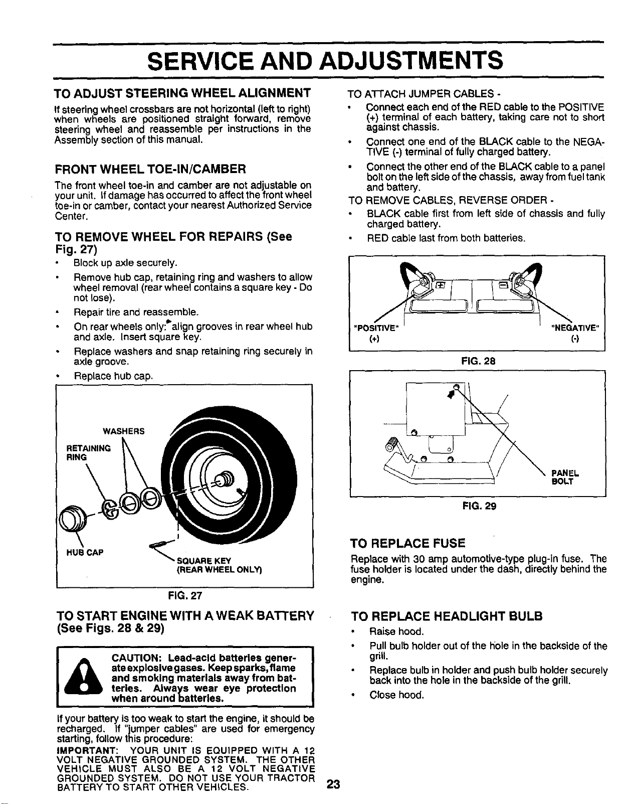
TO REMOVE WHEEL FOR REPAIRS (See
Fig. 27)
Block up axle securely.
Remove hub cap, retaining ring and washers to allow
wheel removal (rear wheel contains a square key - Do
not lose).
Repair tire and reassemble.
On rear wheels only:_'align grooves in rear wheel hub
and axle. Insert square key.
Replace washers and snap retaining ring securely in
axle groove.
• Replace hub cap.
WASHERS
RETAINING
RING
HUB CAP
_SQUARE KEY
(REAR WHEEL ONLY)
FIG. 27
TO START ENGINE WITH A WEAK BATTERY
(See Figs. 28 & 29)
CAUTION: Lead-acid batteries gener-
ate explosive gases. Keep sparks, flame
and smoking materials away from bat-
teries. Always wear eye protection
when around batteries.
If your battery is too weak to start the engine, it should be
recharged. If "jumper cables" are used for emergency
starting, follow this procedure:
IMPORTANT: YOUR UNIT IS EQUIPPED WITH A 12
VOLT NEGATIVE GROUNDED SYSTEM. THE OTHER
VEHICLE MUST ALSO BE A 12 VOLT NEGATIVE
GROUNDED SYSTEM. DO NOT USEYOURTRACTOR
BATTERY TO START OTHER VEHICLES.
23
TO A1-FACH JUMPER CABLES -
Connect each end of the RED cable to the POSITIVE
(+) terminal of each battery, taking care not to short
against chassis.
Connect one end of the BLACK cable to the NEGA-
TIVE (-) terminal of fully charged battery.
• Connect the other end of the BLACK cable to a panel
bolton the leftside of the chassis, away from fuel tank
and battery.
TO REMOVE CABLES, REVERSE ORDER -
BLACK cable first from left side of chassis and fully
charged battery.
RED cable last from both batteries.
"POSITIVE" "NEGATIVE"
(+) (-)
FIG. 28
PANEL
BOLT
FIG. 29
TO REPLACE FUSE
Replace with 30 amp automotive-type plug-in fuse. The
fuse holder is located under the dash, directly behind the
engine.
TO REPLACE HEADLIGHT BULB
Raise hood.
Pull bulb holder out of the hole in the backside of the
grill.
Replace bulb in holder and push bulb holder securely
back into the hole in the backside of the grill.
Close hood.

ml ill
SERVICE AND ADJUSTMENTS
ENGINE
TO ADJUST THRO'I-I'LE CONTROL CABLE
(See Fig. 30)
The throttle control has been preset at the factory and
adjustment should not be necessary. Check adjustment as
described below before loosening cable. If adjustment is
necessary, precede as follows:
With engine not running, move throttle control lever
from "SLOW" to "CHOKE" position. Slowly move lever
from "CHOKE" to "FAST" position.
Check to see if hole in throttle lever and hole in speed
control bracket are aligned.
If holes are not aligned, loosen cable clamp screw and
align the holes by inserting a pencil or a 1/4" drill bit
through both holes.
Pull throttle cable up to remove slack and tighten cable
clamp screw. Remove alignment pencil or drill bit.
TO ADJUST CARBURETOR (See Fig. 31)
The carburetor has been preset at the factory and adjust-
ment should not be neces,_iary. However, minor adjust-
ment may be required to corn pensate for differences in fuel,
temperature, altitude or load. Ifthe carburetor does need
adjustment, proceed as follows:
In general, turning the adjusting needles in (clockwise)
decreases the suppl=yof fuel to the engine giving a leaner
fuel/air mixture. Turning the ad usting needles out
(countercockwise) ncreases the supp y of fuel to the
engine giving a richer fuel/air mixture.
IMPORTANT; DAMAGE TO THE NEEDLES AND THE
SEATS IN CARBURETOR MAY RESULT IF NEEDLE IS
TURNED IN TOO TIGHT.
PRELIMINARY SETTING -
Be sure you have a clean air filter and the throttle
control cable is adjusted properly (see above).
With engine off turn idle fuel adjusting needle in
(clockwise) closing it finger tight and then turn out
(counterclockwise) 1 turn.
FINAL SETTING -
Start engine and allow to warm for five minutes. Make
final adjustments with engine running and shift/motion
control lever in "NEUTRAL" position.
Idle seeed settina -With throttle control lever in"SLOW"
position, engine should idle at 1625 RPM. If engine
idles too slow or fast, turn idle speed adjusting screw in
or out until correct idle is attained.
Idle fuel needle settina - With throttle control lever in
"SLOW" position, turn idle fuel adjusting needle in
(clockwise) until engine begins to die and then turnout
(counterclockwise) approximately 1/8 to 1/4 turn to
obtain best low speed performance.
Recheck idle speed. Readjust if necessary.
ACCELERATION TEST -
Move throttle control lever from "SLOW" to "PAST"
position. If engine hesitates or dies, turn idle fuel
adjusting needle out (counterclockwise) 1/8 turn. Re-
peat test and continue to adjust, if necessary, until
engine accelerates smoothly.
High speed stop is factory adjusted. Do not adjust -
damage may result.
IMPORTANT: NEVER TAMPER WITH THE ENGINE
GOVERNOR, WHICH IS FACTORY SET FOR PROPER
ENGINE SPEED. OVERSPEEDING THE ENGI NE ABOVE
THE FACTORY HIGH SPEED SETTING CAN BE
DANGEROUS. IF YOU THINK THE ENGINE-GOVERNED
HIGH SPEED NEEDS ADJUSTING, CONTACT YOUR
NEAREST SEARS SERVICE CENTER, WHICH HAS
PROPER EQUIPMENTAND EXPERIENCETO MAKE ANY
NECESSARY ADJUSTMENTS.
CABLE
CLAMP
SPEED CONTROL
BRACKET
FIG. 30
IDLE SPEED
ADJUS_NO
----... _.
/
IDLE FUEL
ADJUSTING
NEEDLE
FIG. 31
24
STORAGE
ENGINE
Immediately prepare your tractor for storage at the end of
the season or ifthe unitwillnot be used for 30 daysor more.
A
CAUTION: Never store the tractor with
gasoline In the tank Inside a building
where fumes may reach an open flame
or spark. Allow the engine to cool
before storing In any enclosure,
TRACTOR
Remove mower from tractor for winter storage. When
mower is to be stored for a period of time, clean it thor-
oughly, remove all dirt, grease, leaves, etc. Store in a
clean, dry area.
Clean entire tractor (See "CLEANING" in the Customer
Responsibilities section of this manual).
Inspect and replace belts, if necessary (See belt re-
placement instructions in the Service and Adjustments
section of this manual).
Lubricate as shown in the Customer Responsibilities
section of this manual.
Be sure that all nuts, bolts and screws are securely
fastened. Inspect moving partsfordamage, breakage
and wear. Replace if necessary.
Touch up all rusted or chipped paint surfaces; sand
lightly before painting.
BATTERY
Fully charge the battery for storage.
After a period of time in storage, battery may require
recharging.
, To help prevent corrosion and power leakage during
long periods of storage, battery cables should be
disconnected and battery cleaned thoroughly (see"TO
CLEAN BATTERY AND TERMINALS" in the Cus-
tomer Responsibilities section of this manual).
After cleaning, leave cables disconnected and place
cables where they cannot come in contact with battery
terminals.
Be sure battery drain tube is securely attached.
FUEL SYSTEM
IMPORTANT: IT IS IMPORTANT TO PREVENT GUM
DEPOSITS FROM FORMING IN ESSENTIAL FUEL
SYSTEM PARTS SUCH AS CARBURETOR, FUEL FILTER,
FUEL HOSE, OR TANK DURING STORAGE. ALSO,
EXPERIENCE INDICATES THAT ALCOHOL BLENDED
FUELS (CALLED GASOHOL OR USING ETHANOL OR
METHANOL) CAN ATTRACT MOISTURE WHICH LEADS
TO SEPARATION AND FORMATION OF ACIDS DURING
STORAGE. ACIDIC GAS CAN DAMAGE THE FUEL
SYSTEM OF AN ENGINE WHILE IN STORAGE.
Drain the fuel tank.
Start the engine and let it run until the fuel lines and
carburetor are empty.
Never use engine or carburetor cleaner products in the
fuel tank or permanent damage may occur.
Use fresh fuel next season.
NOTE: Fuel stabilizer is an acceptable alternative in
minimizing the formation offuel gum deposits during stor-
age. Add stabilizer to gasoline in fuel tank or storage
container. Always follow the mix ratio found on stabilizer
container. Run engine at least 10 minutes after adding
stabilizer to allow the stabilizer to reach the carburetor. Do
notdrain the gas tank and carburetor ifusing fuel stabilizer.
ENGINE OIL
Drain oil (with engine warm) and replace with clean engine
oil. (See "ENGINE" in the Customer Responsibilities
section of this manual).
CYLINDERS
Remove spark plug(s),
Pour one ounce of oil through spark plug hole(s) into
cylinder(s).
Turn ignitionkey to"START' positionfor afew seconds
to distribute oil.
Replace with new spark plug(s).
OTHER
Do not store gasoline from one season to another.
Replace your gasoline can if your can starts to rust.
Rust and/or dirt in your gasoline will cause problems.
If possible, store your unit indoors and cover itto give
protection from dust and dirt.
Cover your unit with a suitable protective cover that
does not retain moisture. Do not use plastic. Plastic
cannot breathe which allows condensation toform and
will cause your unit to rust.
IMPORTANT: NEVER COVER TRACTOR WHILE ENGINE
AND EXHAUST AREAS ARE STILL WARM.
25

TROUBLESHOOTING POINTS
CAUSE CORRECTIONPROBLEM
Will not start
Hard toatart
Engine will not turn over
Engine clicks but will not
Mert
Lossof power
Excessive vibration
1. Out of fuel.
2. Engine not"CHOKED" properly.
3. Engine flooded.
4. Bad spark plug.
5. Dirty air filter.
6. Dirty fuel filter.
7. Water In fuel.
8. Looseordamagedwiring.
9. Carburetoroutofadjustment.
10. Enginevalvesoutof adjustment.
1, Dirty air filter.
2. Bad spark plug.
3. Weak or dead battery.
4. Dirty fuel filter.
5. Stale or dirtyfuel.
6. Loose or damaged wiring,
7. Carburetor out of adjustment.
8, Engine valves out of adjustment.
1. Clutch/brake pedal not depressed.
2. Attachment clutch is engaged.
3. Spark plug wire is disconnected.
4. Weak or dead battery.
5. Blown fuse.
6. Corroded battery terminals.
7. Loose or damaged wiring.
8. Faulty ignition switch.
9. Faulty solenoid or starter.
10. Faulty operator presence switch(es).
1. Weak or deadbattery.
2. Corrodedbatteryterminals.
3. Looseor damagedwidng.
4, Faultysolenoidor starter.
1. Cuttingtoo muchgrass/toofast,
2, ThrOttlein"CHOKE"position.
3. Build-upofgrass,leaves andtrashundermower.
4. Dirtyairfilter.
5, Lowoil level/dirty oil.
6. Faultyspark plug.
7. Dirtyfuel filter.
8, Stale or dirtyfuel.
9. Water in fue!.
10. Spark plugwire loose.
11. Dirtyengineair ecroen/fins.
12. Dirty/cloggedmuffler.
t3. Looseor damagedwiflng.
t4. Carburetoroutof,adjustment.
15. Enginevalvesout ofadjustment.
1. Worn,bentor looseblade.
2. Rentblademandrel.
3. Loose/damagedpart(s),
1. Ftll fuel tank.
2. See TO START ENGINE In Operation section.
3. Wait several minutes before attempting to start.
4. Replace spark plug.
5. Clean/replace air filter.
6. Replace fuel filter.
7. Drain fuel tank and carburetor, raft, tank with fresh
gasoline and replace fuel filter.
8. Check all widng.
9. Contact Sears Service Department.
10. Contact Sears Service Department.
1, Clean/replace air filter.
2. Replace spark plug.
3. Recharge or replace battery.
4. Replace fuel filter.
5. Drain fuel tank and refill with fresh gasoline.
6. Check all widng.
7. Contact Sears Service Department.
8. Contact Sears Service Department.
1, Depress clutch/brake pedal.
2. Disengage attachment clutch.
3. Connect wire to spark plug.
4. Recharge or replace battery.
5. Replace fuse.
6, Clean battery terminals,
7. Check all wiring.
8. Check/replace ignition switch.
9. Check/replace solenoid or starter.
t0, Contact Sears Service Department.
1. Rechargeor replacebattery,
2. Cleanb_.tteryterminals,
3. Checkallwidng.
4. Check/replacesolenoid orstarter.
1. Set in "Higher Cut"positioniraducespeed.
2. Adjustthrottlecontrol.
3. Cleanundersideofmowerhousing.
4. Clean/replaceairfitter.
5. Checkoil level/changeoil.
6. Clean andregap orchangesparkplug,
7. Replacefuel fitter.
8. Drainfuel tank andrefillwithfresh gasoline.
9. Drainfuel tank andcarburetor,refilltankwithfTesh
gasolineand replacefuel filter.
10. Connectand tightenspark plugwire.
i 11. Clean engineair screen/fins.
12. Clean/replacemuffler.
13. Checkall widng.
j 14. ContactSears ServiceDepartment,
15. ContactSears ServiceDepartment.
1, Replaceblade. Tightenbladebolt.
2, Replaceblademandrel.
3, Tightenloosepart(s). Replacedamagedparts.
26
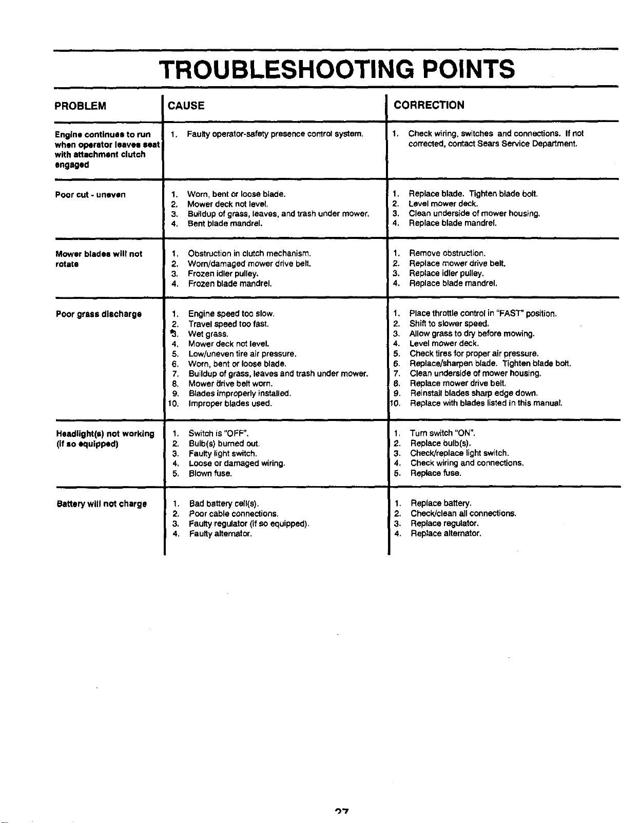
TROUBLESHOOTING POINTS
PROBLEM CAUSE
Engine continues to run
when operator leaves seat
with attachment clutch
engaged
Poor cut - uneven
Mower blades will not
rotate
Poor grass discharge
Headllght(=) not working
(ifso equipped)
Batterywill not charge
1. Faulty operator-safety presence control system,
1. Worn, bent or loose blade.
2. Mower deck not leval.
3. Buildup of grass, leaves, and trash under mower.
4. Bent blade mandrel.
1. Obstruction in clutchmechanism.
2. Worn/damaged mowerdrive belt.
3. Frozenidlerpulley.
4. Frozen blademandrel.
1. Engine speedtoo slow.
2. Travel speed too fast.
_.. Wet grass.
4. Mower deck not level.
5. Low/uneven tire air pressure.
6. Worn, bent or loose blade.
7, Buildup of grass, leaves and trash under mower.
8. Mower drive belt worn.
9. Blades improperly installed.
10. Improper blades used.
1. Switch is "OFF",
2. Bulb(s) burned out,
3. Faulty light switch.
4, Loose or damaged wiring,
5. Blown fuss.
1. Bad batterycell(s).
2. Poorcableconnections.
3. Faultyregulator(ifso equipped).
4. Faultyalternator.
CORRECTION
i
1. Check widng, switches and connections. If not
corrected, contact Sears Service Department.
1. Replace blade, Tighten blade bolt,
2, Level mower deck.
3. Clean underside of mower housing,
4. Replace blade mandrel.
1. Remove obstruction.
2. Replace mower drive belt.
3, Replace idler pulley.
4, Replace blade mandrel.
1. Place throttle control in =FAST" position.
2. Shift to slower speed.
3, Allow grass to dry before mowing.
4. Level mower deck.
5. Check tires for proper air p¢'sssurs.
6. Replace/sharpen blade. Tighten blade bolt.
7. Clean underside of mower housing.
8. Replace mower drive belt.
9. Reinstall blades sharp edge down.
I0, Replace with blades listed in this manual.
1, Turn switch "ON".
2. Replace bulb(s).
3. Check/replace light switch.
4, Check wiring and connections.
5. Replace fuse.
1, Replacebattery.
2. Check/clean allconnections.
3. Replace regulator.
4. Replacealternator.
")'7
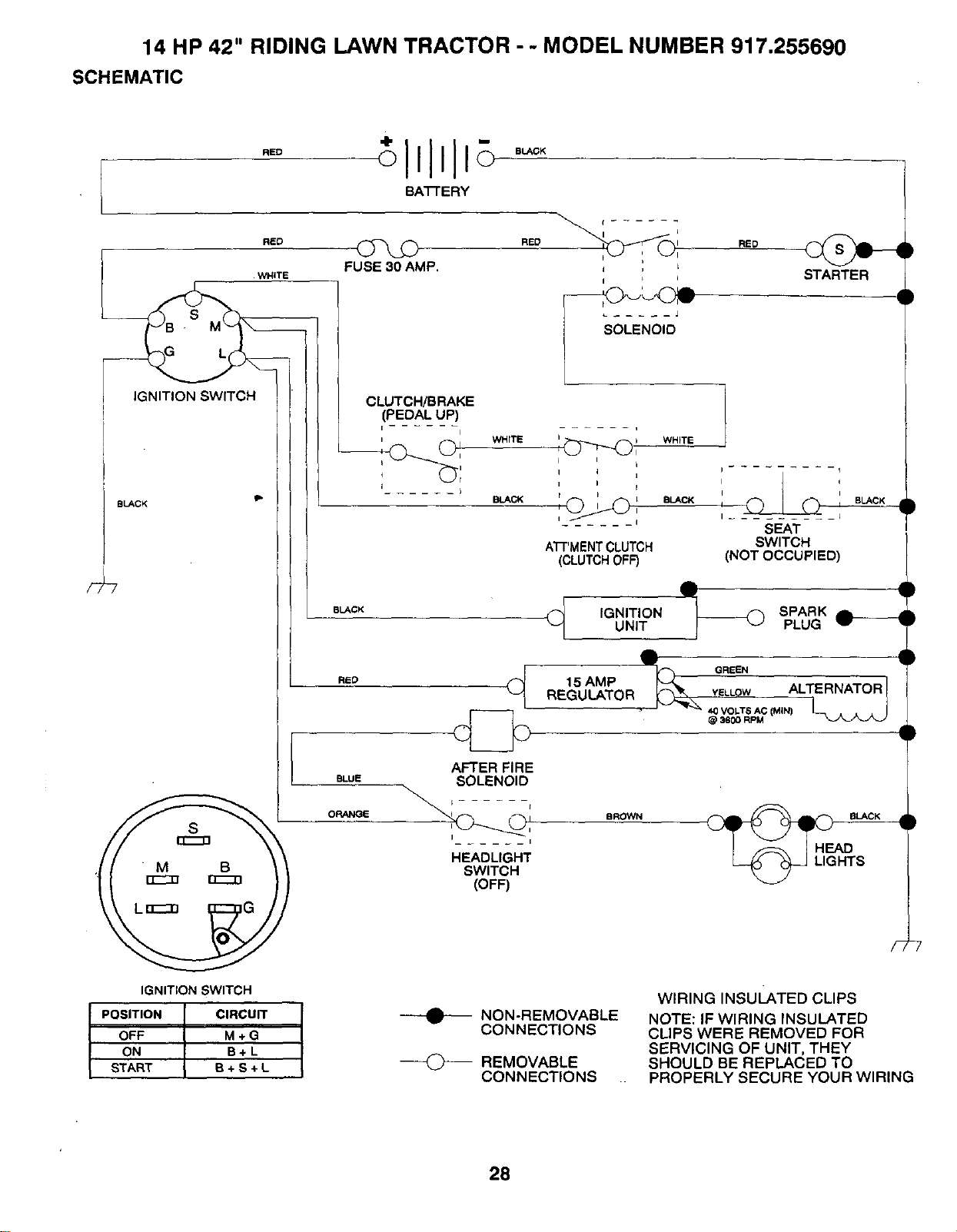
14 HP 42" RIDING LAWN TRACTOR - - MODEL NUMBER 917.255690
SCHEMATIC
BLACK
F_
RED
BA'FrERY
RED _ RED_0
FUSE 30 AMP.
WHITE STARTER
• M B
IGNITION SWITCH
POSITION CIRCUIT
OFF M + G
ON B+ L
START B+ S ÷L
RED I I
_C_ ' -.
_ ..... J
I SOLENOID
BLACK
CLUTCH/BRAKE
(PEDAL UP)
I i I
oi W.TE W.TE
i I i
I 1 BLAC K _ _ EL_CK
I
_1
AFTER FIRE
BLUE SOLENOID
I_ _ _ I
HEADLIGHT
SWITCH
(OFF)
)
)
I I
SEAT
ATPMENTCLUTCH SWITCH
(CLUTCH0FF) (NOT OCCUPIED)
L
I
BLACK •
IGNITION SPARK
UNIT PLUG
15AMP _ GREEN
REGULATOR V_L_L_OW ALTERNATOR I
- _ 40 VOLTS AC (MIN)
@ 3600 RPM
BROWN
T
)
)
s_cK
HEAD
HTS
NON-REMOVABLE
CONNECTIONS
REMOVABLE
CONNECTIONS
WIRING INSULATED CLIPS
NOTE: IF WIRING INSULATED
CLIPS WERE REMOVED FOR
SERVICING OF UNIT, THEY
SHOULD BE REPLACED TO
PROPERLY SECURE YOUR WIRING
28

SERVICE NOTES
29
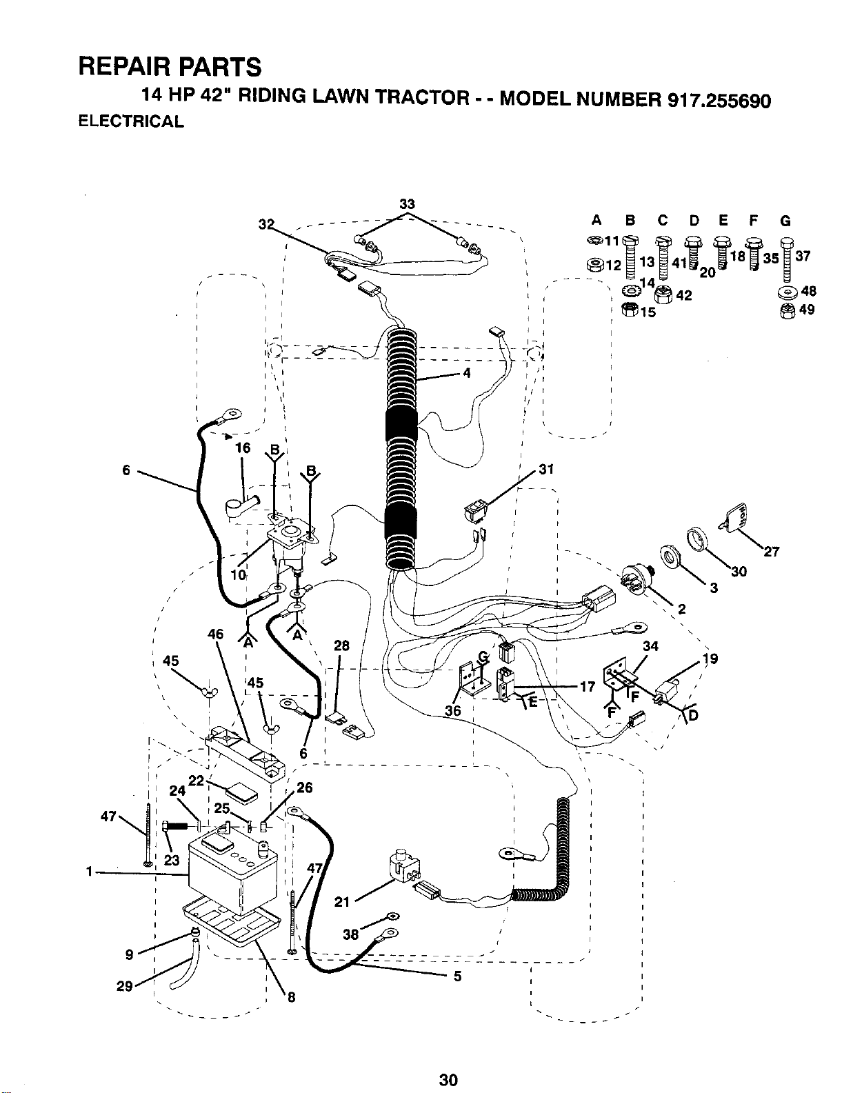
REPAIR PARTS
14 HP 42" RIDING LAWN TRACTOR - - MODEL NUMBER 917.255690
ELECTRICAL
6
46
45
I i
I
16
6 i
26
21
8
33
A B C D E F G
_12 13 4 8_35 37
r _15 _49
3
34 \
!9
/
/
/
\/
30

REPAIR PARTS
14 HP 42" RIDING LAWN TRACTOR - - MODEL NUMBER 917.255690
ELECTRICAL
KEY PART
NO. NO. DESCRIPTION
1 121537X
2 102972X
3 124211X
4 133135
5 4207J
6 4206J
8 7603J
9 109596X
10 109081X
11 STD551125
12 73350400
13 74780408
14 STD551225
15 STD541425
16 131563
17 109553X
18 STD601005
19 104445X
20 STD601005
21 121305X
22 121264X
23 74760412
24 STD551025
25 STD551125
26 STD541025
27 109310X
28 108824X
29 100541K
30 123620X
31 110712X
32 127441X
33 4152J
34 108236X
35 STD601005
36 110923X
37 74760616
38 STD551237
45 123198X
46 102476)(
47 STD532575
48 19131312
49 STD541437
Battery 12 Volt 30 Amp
Switch Ignition 5 Term
Nut Ignition
Harness Ign Koh Dash HI
Cable Ground 6ga 12"black
Cable Battery 6ga 22" Red
Tray Battery 7 80 x 5 25 BIk
Clamp Hose Olive
Solenoid
Lockwasher
Nut Jam Hex 1/4-20 Unc
Bolt Fin Hex 1/4-20uncx1/2 Gr5
Washer
Nut
Cover Terminal Red
Switch Intlk Clutch Red 4 Term
Screw
Switch Intlk Clutch Red 2 Term
Screw
Switch Plunger Nc Gray
Caps Battery 20/25/30 Amp
Bolt Hex Hd 1/4-20unc x 3/4
Washer
Washer
Nut
Key Ign Molded Craftsman
Fuse 30 Amp Auto Green '
Tube Plastic 31"
Cover Sw Key BIk I 25 Text Sit
Switch Light BIk BIk Red
Harness Socket Light
Bulb Light #1156
Bracket Switch Clutch
Screw
Bracket Mower Clutch
Bolt Hex 3/8-16 x 1
Washer
Nut Plastic Locking Wng 1/4-20
Guard Terminal BIk
Bolt.
Washer 13/32 x 13/16 x 12 Ga
Nut
NOTE: AIIcomponent dimensions givenin U.S. inches
1 inch = 25.4mm
31
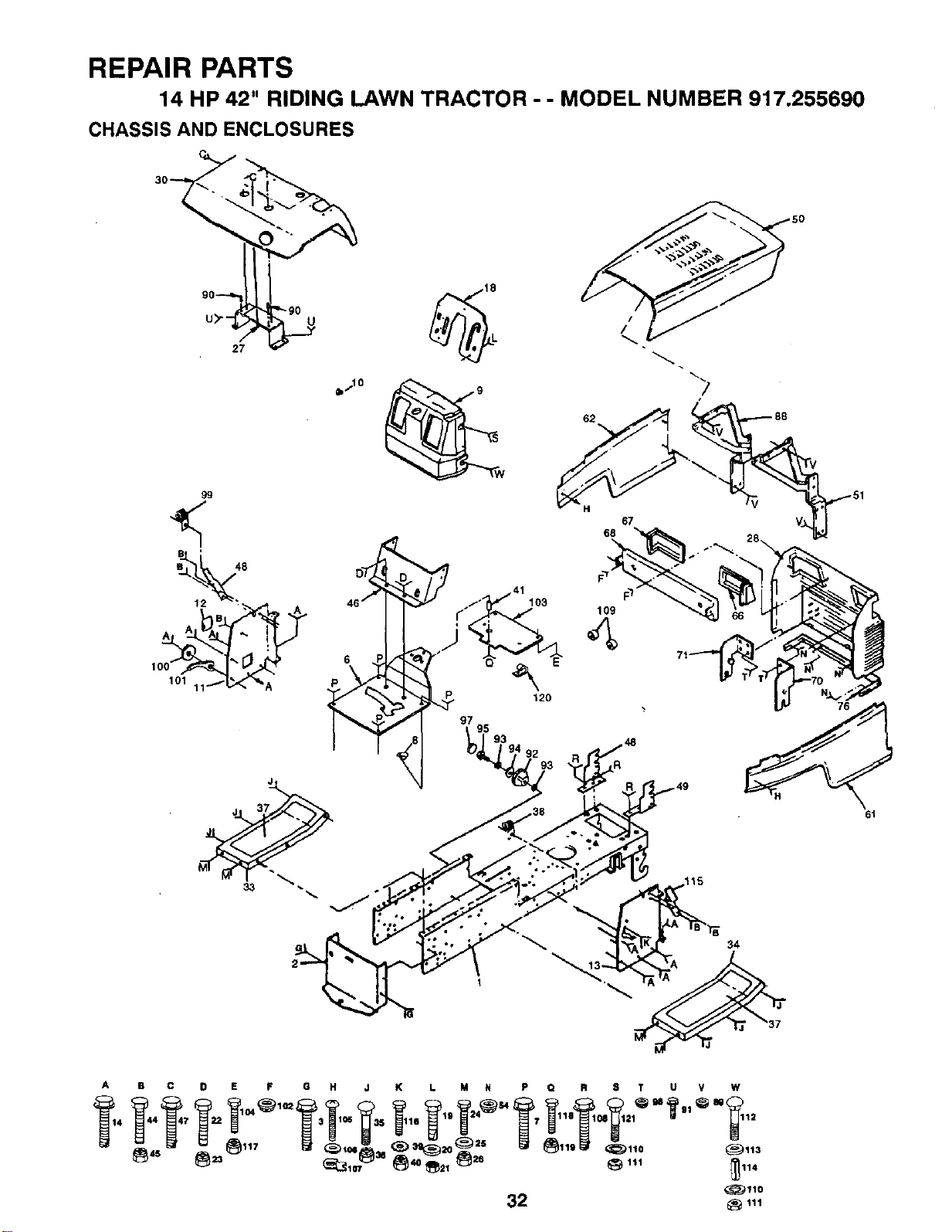
REPAIR PARTS
14 HP 42" RIDING LAWN TRACTOR - - MODEL NUMBER 917.255690
CHASSIS AND ENCLOSURES
50
/
62
H
67
68
A B C D E F G H J K L M N P Q R 8 T U V W
_4 _44_47 _22 _104_102_3_105 _35 _116 _19 _24_$4 _? _118_1M_21_ M_'I _"_ 12
32 _ 111
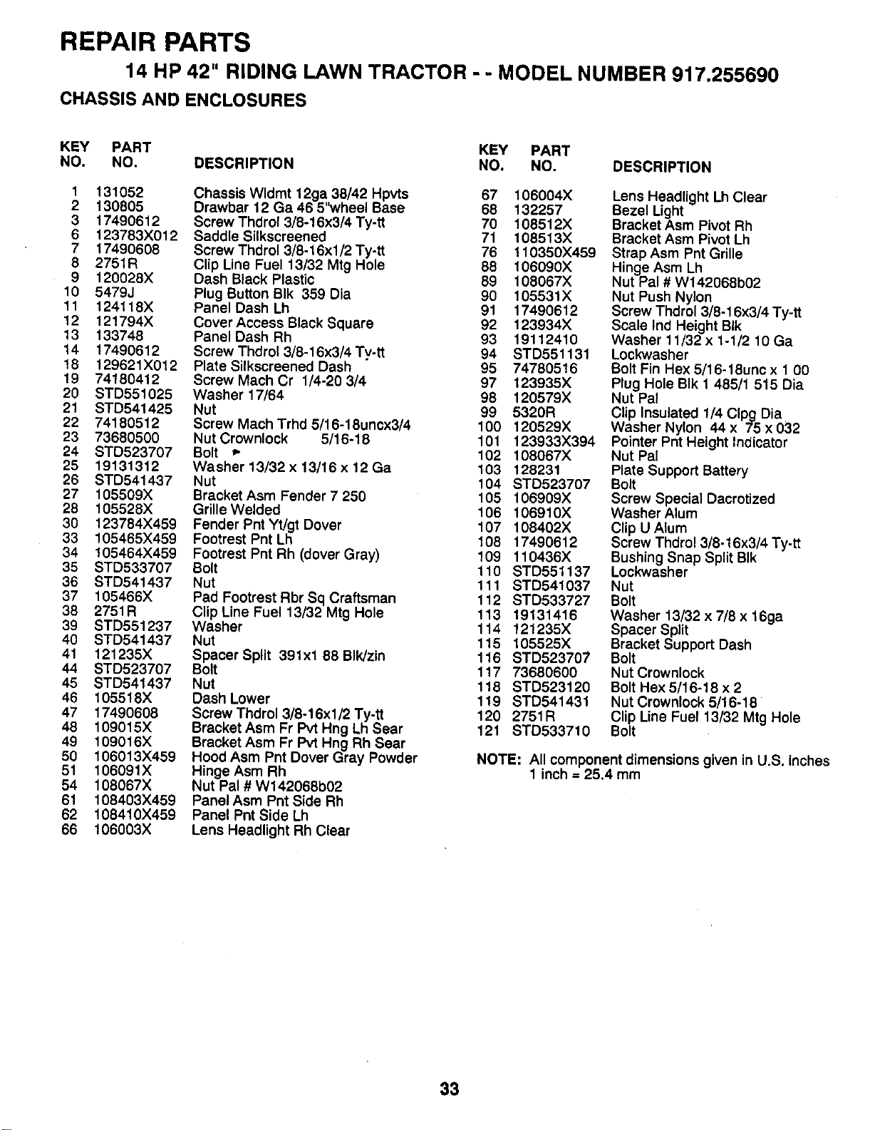
REPAIR PARTS
14 HP 42" RIDING LAWN TRACTOR - - MODEL NUMBER 917.255690
CHASSIS AND ENCLOSURES
KEY PART KEY PART
NO. NO. DESCRIPTION NO. NO. DESCRIPTION
1 131052
2 130805
3 17490612
6 123783X012
7 17490608
8 2751R
9 120028X
10 5479J
11 124118X
12 121794X
13 133748
14 17490612
18 129621X012
19 74180412
20 STD551025
21 STD541425
22 74180512
23 73680500
24 STD523707
25 19131312
26 STD541437
27 105509X
28 105528X
30 123784X459
33 105465X459
34 105464X459
35 STD533707
36 STD541437
37 105466X
38 2751R
39 STD551237
40 STD541437
41 121235X
44 STD523707
45 STD541437
46 105518X
47 17490608
48 109015X
49 109016X
50 106013X459
51 106091X
54 108067X
61 108403X459
62 108410X459
66 106003X
Chassis Wldmt 12ga,,38/42 Hpvts 67 106004X
Drawbar 12 Ga 46 5 wheel Base 68 132257
Screw Thdrol 3/8-16x3/4 Ty-tt 70 108512X
Saddle Silkscreened 71 108513X
Screw Thdrol 3/8-16xl/2 Ty-tt 76 ! 10350X459
Clip Line Fuel 13/32 Mtg Hole 88 106090X
Dash Black Plastic 89 108067X
Plug Button BIk 359 Dia 90 105531X
Panel Dash Lh 91 17490612
Cover Access Black Square 92 123934X
Panel Dash Rh 93 19112410
Screw Thdrol 3/8-16x3/4 Tv.tt 94 STD551131
Plate Silkscreened Dash 95 74780516
Screw Mach Cr 1/4-20 3/4 97 123935X
Washer 17/64 98 120579X
Nut 99 5320R
Screw Mach Trhd 5/16-18uncx3/4 100 120529X
Nut Crownlock 5/16-18 101 123933X394
Bolt _" 102 108067X
Washer 13/32 x 13/16 x 12 Ga 103 128231
Nut 104 STD523707
Bracket Asm Fender 7 250 105 106909X
Grille Welded 106 106910X
Fender Pnt Yt/gt Dover 107 108402X
Footrest Pnt Lh 108 17490612
Footrest Pnt Rh (dover Gray) 109 110436X
Bolt 110 STD551137
Nut 111 STD541037
Pad Footrest Rbr Sq Craftsman 112 STD533727
Clip Line Fuel 13/32 Mtg Hole 113 19131416
Washer 114 121235X
Nut 115 105525X
Spacer Split 391xl 88 BIk/zin 116 STD523707
Bolt 117 73680600
Nut 118 STD523120
Dash Lower 119 STD541431
Screw Thdrol 3/8-16xl/2 Ty-tt 120 2751R
Bracket Asm Fr Pvt Hng Lh Sear 121 STD533710
Bracket Asm Fr Pvt Hng Rh Sear
Hood Asm Pnt Dover Gray Powder
Hinge Asm Rh
Nut Pal # W142068b02
Panel Asm Pnt Side Rh
Panel Pnt Side Lh
Lens Headlight Rh Clear
Lens Headlight Lh Clear
Bezel Light
Bracket Asm Pivot Rh
Bracket Asm Pivot Lh
Strap Asm Pnt Grille
Hinge Asm Lh
Nut Pal # W142068b02
Nut Push Nylon
Screw Thdrol 3/8-16x3/4 Ty-tt
Scale Ind Height BIk
Washer 11/32 x 1-1/2 10 Ga
Lockwasher
Bolt Fin Hex 5/16-18unc x 1 00
Plug Hole BIk 1 485/1 515 Dia
Nut Pal
Clip Insulated 1/4 Clpg Dia
Washer Nylon 44 x 75 x 032
Pointer Pnt Height Indicator
Nut Pal
Plate Support Battery
Bolt
Screw Special Dacrotized
Washer Alum
Clip U Alum
Screw Thdrol 3/8-16x3/4 Ty-tt
Bushing Snap Split BIk
Lockwasher
Nut
Bolt
Washer 13/32 x 7/8 x 16ga
Spacer Split
Bracket Support Dash
Bolt
Nut Crownlock
Bolt Hex 5/16-18 x 2
Nut Crownlock 5/16-18
Clip Line Fuel 13/32 Mtg Hole
Bolt
NOTE: All component dimensions given in U.S. inches
1 inch = 25.4 mm
33
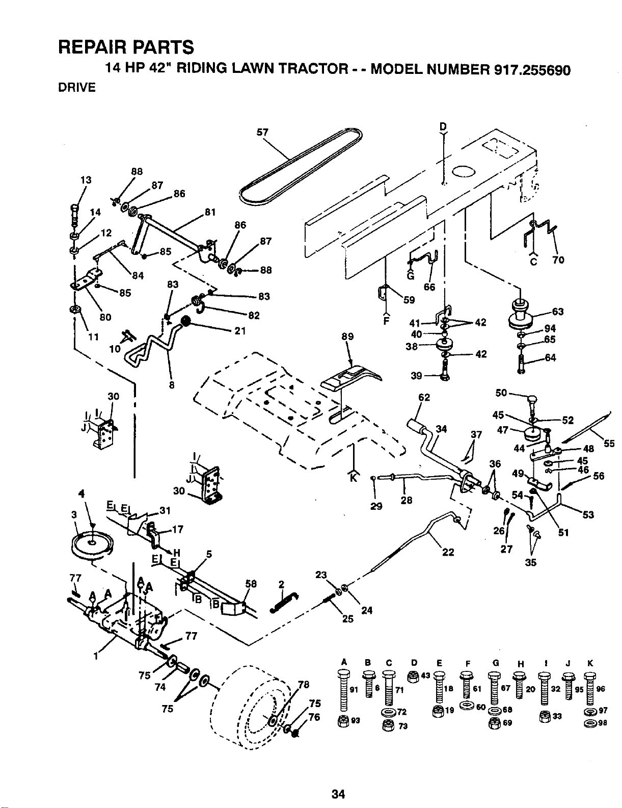
REPAIR PARTS
14 HP 42" RIDING LAWN TRACTOR - - MODEL NUMBER 917.255690
DRIVE
13
88
4
3
86
77
22
35
5
74
75
B C D E F G H I J K
/ ,,/, _ .TS
34

REPAIR PARTS
14 HP 42" RIDING LAWN TRACTOR - - MODEL NUMBER 917.255690
DRIVE
KEY PART KEY PART
NO. NO. DESCRIPTION NO. NO. DESCRIPTION
1 131965 Transaxle 6 Sp Medium Dana 54 STD561210
2 110422X Spring Return Brake T/a Zinc 55 105709X
3 123667X Pulley Transaxle 20"tires 56 STD561210
4 12000028 Ring Retainer # 5100-62 57 131006
5 121520X Strap Torque 30 Degrees 58 127290
6 17490512 ScrewThdrol 5/16-18 x3/4Tyt 59 104777X
8 127288X Rod Shifter Fender Yt 14 3251g 60 19131312
10 STD561210 Pin 61 17490612
11 105701X Washer Plate Shf 388 Sq Hole 62 8883R
12 19151216 Washer15/32x3/4x16ga 63 131002
13 71040412 Bolt Fin Hex 1/4-28unfx3/4 Gr8 64 M010110110
14 STD551125 Washer Lock Hvy Helical 65 STD551143
17 121520X Strap Torque 30 Degrees 66 t29921
18 STD523707 Bolt _. 67 STD523710
19 STD541437 Nut 68 19131312
20 17490512 Screw Thdrol 5/16-18 x 3/4 Tyt 69 STD541437
21 106933X Knob Rd 1/2-13 PlstcThdsBIk 70 131402
22 130804 Rod Brake BIk Zinc 26 840 71 STD523710
23 STD541437 Locknut 72 19132012
24 STD541237 Nut 73 STD541437
25 106888X Spring Rod Brake 2 00 Zinc 74 109502X
26 STD551037 Washer 75 121749X
27 STD561210 Pin 76 STD581075
28 133261 Rod Brake Parking 14 500 77 123583X
29 124236X Cap Parking Brake Red 78 121748X
30 130807 Bracket Mtg Transaxle 80 131487
31 127289 KeeperBeltLhYt14Ga 81 131811
32 STD523107 Bolt 82 123782X
33 STD541431 Nut 83 19171216
34 122424X Shaft Asm Pedal Foot 1 930 84 132183
35 120183X Bearing Nylon BIk 629 Id 85 73530400
36 STD551062 Washer 85 73530400
37 STD571810 Roll Pin 86 127272X
38 123674X Pulley Idler Flat 87 126591X
39 STD523727 Bolt 88 STD581050
40 4470J Spacer Split 395 x 59 Bzp 89 127287X
41 109070X Keeper Belt Retainer 91 74760540
42 19131312 Washer 13/32 x 13/16x 12 Ga 93 STD541431
43 STD541437 Nut 94 126197X
44 105706X Bearing Nyl 503 x 628x 1 25 95 17490612
45 110812X Washer Hardened 96 74640808
46 12000039 Ring Klip #t5304-50 97 10100800
47 127783 Pulley Idler V Groove Plastic 98 19060718
48 123789X Bellcrank Asm
49 123205X Retainer Belt Style Spring
50 STD523715 Bolt
51 STD541437 Nut
52 STD551037 Washer
53 105710X Link Clutch 7 66
Pin
Spring Return Clutch 6 75
Pin
V-belt Gnd Dr 98 25 Yt Stretch
Keeper Belt Rh Yt Pnt/zinc 16g
Retainer Belt Chassis Lh Zinc
Washer 13/32 x 13/1€"x 12 Ga
Screw Thdrol 3/8-16x,_/4 Ty-tt
Cover Pedal BIk Round
Pulley Engine
Bolt Hex M10-1 5xl 10
Washer
Keeper Belt Engine Lh Lt
Bolt
Washer 13/32 x 13/16 x 12 Ga
Nut
Guide Belt Dr Mower Rh
Bolt
Washer 13/32 x 1-1/4 x 12 Ga
Nut
Spacer Split 80xl 94 Cad/zinc
Washer 25/32 x 1 1/4 x 16 Ga
E Ring
Key Square 2 0 x 1845/1865
Washer 25/32 x 1 5/8 x 16ga
Arm Shift Transaxle
Shaft Asm Shifter
Spring Torsion T/a
Washer 17/32 x 3/4 x 16ga
Rod Tie Shf Adj Ball Jt 4 650
Nut Nylock 1/4-28
Nut Nylock 1/4-28
Bushing Pivot W/180 Step Pm
Washer Shim 53 x 1 25 x 0598
E Ring
Console Shift 6sp Wo/ign Yt Da
Bolt Fin Hex 5/16-18uncx 2-1/2
Nut
Washer 1-1/2 Odxl 5/32 Idx 250
Screw Thdrol 3/8-16x3/4 Ty-tt
Screw #8xl/2
Washer Lock #8
Washer 3/16 x 7/16 x 18 Ga
NOTE: All component dimensions given in U.S. inches
1 inch = 25.4 mm
35
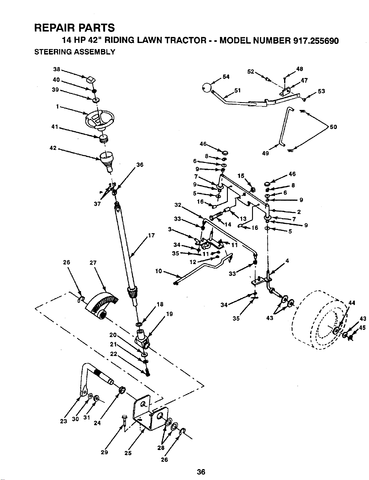
REPAIR PARTS
14 HP 42" RIDING LAWN TRACTOR - - MODEL NUMBER 917.255690
STEERING ASSEMBLY
38
39
36
26
31
23 24
28
29 25
26
36

REPAIR PARTS
14 HP 42" RIDING LAWN TRACTOR - - MODEL NUMBER 917.255690
STEERING ASSEMBLY
KEY PART
NO. NO. DESCRIPTION
1 100713N
2 131450
3 130460
4 130459
5 6266H
6 121748X
7 19272016
8 12000029
9 3366R
10 130468
11 STD551137
12 73610600
13 110438X
14 74011056
15 73601000
16 132624
17 128755
18 57079
19 124035X
20 126684X
21 STD551125
22 71070410
23 127501
24 109816X
25 124036X
26 12000029
27 124034X
28 6266H
29 17490612
30 STD551137
31 73610600
32 130465
33 120754X
34 19131416
35 STD561210
36 1554J
37 STD523710
38 100710L
39 100712K
40 STD541350
41 100711L
42 110709X
43 121749X
44 121748X
45 12000029
46 121232X
47 131672
48 17490612
49 131291
50 STD561210
51 125916X
52 106451X
53 STD541437
54 106933X
Wheel Steering Ayp Black
Axle Asm Front Lt 38/42
Spindle Asm Lh
Spindle Asm Rh
Bearing Race Thrust Harden
Washer 25/32 x 1 5/8 x 16ga
Washer 27/32 x 1 1/4 x 16 Ga
Ring Klip #t5304-75
Bearing Col Strg BIk
Link DragSol Ball Jt 20 064
Lockwasher
Nut Fin Hex 3/8-24 Unf
Spacer Bearing Axle Front
Bolt Hex 5/8-11 Unc x 3-1/2
Nut Hex Jam Lk Whvh 5/8-11 Unc
Pin Axle 5/8 x 1 55/1 54 Lg
Shaft Asm Strg 17 69 x 3/4 Yt
Washer Thrust 515x 750x 033
Support Shaft
Washer Shim 1/4 x 5/8 x 062
Washer
Screw Hex Socket 1/4-20 x 5/8
Shaft Asm Pittman
Nyliner Snap In
Bracket Steering
Ring Klip #t5304-75
Gear Sector
BearingRace Thrust Harden
Screw Thdrol 3/8-16x3/4 Ty-tt
Lockwasher
Nut Fin Hex 3/8-24 Unf
Rod Tie Wire Form 19 75 Mech
Bushing Rod Tie BIk Lt
Washer 13/32 x 7/8 x 16ga
Pin
Bushing Strg BIk 742/747 Id
Bolt
Insert Cap Strg Wheel Std BIk
Washer 53 x 2 25 x 160 Zinc
Nut
Adapter Wheel Strg 758/753id
Column Steering
Washer 25/32 x 1 1/4 x 16 Ga
Washer 25/32 x 15/8 x 16ga
Ring Klip #t5304-75
Cap Spindle Fr Top BIk
Bracket Pvt Man CI Lvr V2 Sear
Screw Thdrol 3/8-16x3/4 Ty-tt
Link Clutch W/nibs 5 688 Zinc
Pin
Lever Assembly Clutch Mower
Bolt Shoulder 3/8-16 Unc Gr 2
Nut
Knob Rd 1/2-13 Plstc Thds BIk
NOTE: All component dimensions given in U.S. inches
1 inch = 25.4 mm
37
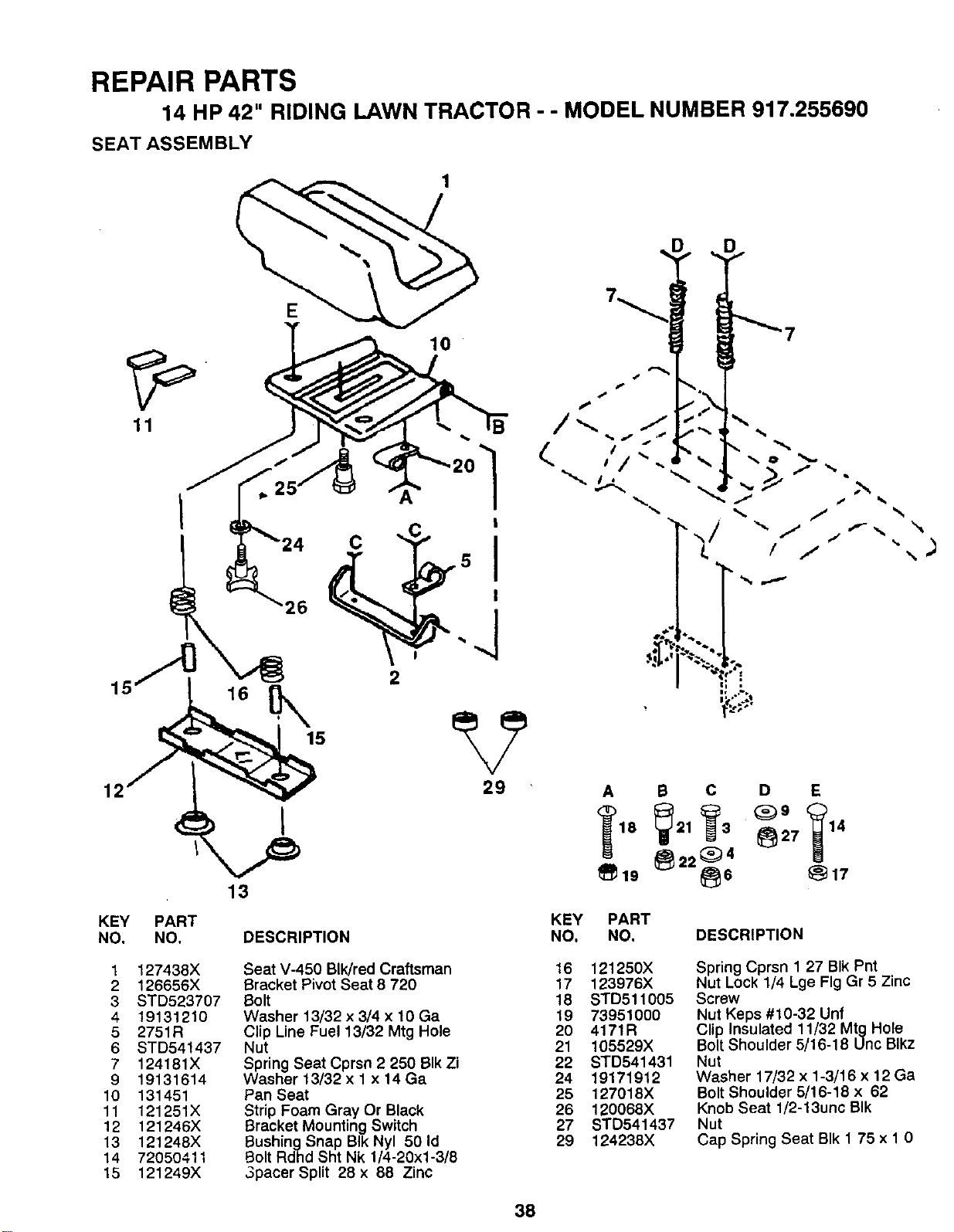
REPAIR PARTS
14 HP 42" RIDING LAWN TRACTOR -- MODEL NUMBER 917.255690
SEAT ASSEMBLY
11
I
KEY PART
NO. NO.
1 127438X
2 126656X
3 STD523707
4 19131210
5 2751R
6 STO541437
7 124181X
9 19131614
10 131451
11 121251X
12 121246X
13 121248X
14 72050411
15 121249X
16
13
C
!
2
29
26
A B C D E
1_19 _22_64 _17
DESCRIPTION
Seat V-450 BIk/red Craftsman
Bracket Pivot Seat 8 720
Bolt
Washer 13/32 x 3/4 x 10 Ga
Clip Line Fuel 13/32 Mtg Hole
Nut
Spring Seat Cprsn 2 250 BIk Zi
Washer 13/32 x 1 x 14 Ga
Pan Seat
Strip Foam Gray Or Black
Bracket Mounting Switch
BushingSnap BIk Nyl 50 Id
Bolt Rdhd Sht Nk 1/4-20xl-3/8
3pacer Split 28 x 88 Zinc
KEY PART
NO. NO. DESCRIPTION
16 121250X
17 123976X
18 STD511005
19 73951000
2O 4171R
21 105529X
22 STD541431
24 19171912
25 127018X
26 120068X
27 STD541437
29 124238X
Spring Cprsn 1 27 BIk Pnt
Nut Lock 1/4 Lge Fig Gr 5 Zinc
Screw
Nut Keps #10-32 Unf
Clip Insulated 11/32 Mtg Hole
Bolt Shoulder 5/16-18 Unc Blkz
Nut
Washer 17/32 x 1-3/16 x 12 Ga
Bolt Shoulder 6/16-18 x 62
Knob Seat 1/2-13unc BIk
Nut
Cap Spring Seat BIk 1 75 x 1 0
38

REPAIR PARTS
14 HP 42" RIDING LAWN TRACTOR - - MODEL NUMBER 917.255690
DECALS
9
13 18 6 2 3 7 8 5 8 20 4 22 13 10
21
15 19
14
11
16
12
23
KEY PART
NO. NO.
1 108456X
2 133178
3 128490
4 128491
5 105806X
6 133644
7 106814X
8 133204
9 128314
10 133796
11 4900J
12 109199X
DESCRIPTION
Decal Instruction Operat Eng
Decal Mower 3 In One Cony
Decal Hood Rh Craftsman Yt/gt
Decal Hood Lh Craftsman Yt/gt
Decal Grille (craftsman)
Decal Maint Cust Sears Domesti
Decal Stripe Panel Side Rh
Decal Pnl Side Kohler Ohv 14hp
Decal Fender Craftsman White
Decal Caution English
Decal Clutch/brake English
Decal V-belt Dr Sch Tractor E
WHEELS & TIRES
;,8
,10
7
11
KEY PART
NO. NO.
13 131473
14 130981
15 121343X
16 3713J
17 133179
18 132268
19 120960X
20 106813X
21 132271
22 128258
23 106202X
-- 133129
DESCRIPTION
Decal Chassis 6sp 42"
Decal V-belt Schematic 42"eng
Decal Danger English
Decal Rota Blades English
Decal Mower Qc System
Decal Insr Wh Strg Crafts Usa
Decal Battery Die Hard
Decal Stripe Panel Side Lh
Decal Lt4000 Usa
Decal Hood & Grille Lt4000
Reflector Taillight Red/amber
Manual Owners 255690 Eng
KEY PART
NO. NO. DESCRIPTION
1 59192
2 65139
3 106222X
4 59904
5 106732X311
6 278H
7 9040H
8 106108X311
9 124632X
10 7152J
11 104757X
Cap Valve Tire
Stem Valve
Tire F Ts 15 x 6 0 - 6 Service
Tube Front (Service Item Only)
Rim Asm 6"front White Service
Fitting Grease (Front Wheel Only)
Bearing Flange (Front Wheel Only)
Rim Asm 8xrear White Service
Tire Rear (Service Item Only)
Tube Rear 9 5 x 8 Service
Cap Axle BIk 1 50 x 1 00
NOTE: All component dimensions given in U.S. inches
1 inch = 25,4 mm
39
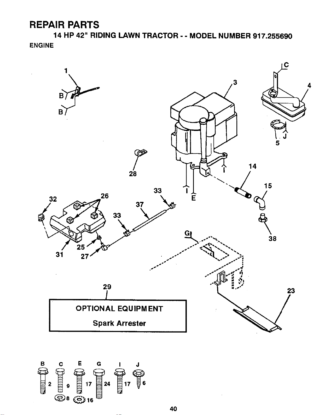
REPAIR PARTS
14 HP 42" RIDING LAWN TRACTOR - - MODEL NUMBER 917.255690
ENGINE
C
1
32 26 28_ 33
37
33
i •
31
OPTIONAL EQUIPM ENT
Spark Arrester
23
B C E G I J
_8 _1_
40

REPAIR PARTS
14 HP 42" RIDING LAWN TRACTOR - - MODEL NUMBER 917.255690
ENGINE
KEY PART
NO. NO. DESCRIPTION
1 134265
2 17720410
3 132499
4 124196X
5 101326L
6 17030808.
8 STD551131
9 STD523105
14 13280336
15 13200300
16 STD551231
17 M010208025
23 128953
24 STD601005
25 3645J
26 106082X
27 8710J
28 2751R
29 121851X
31 106020X
32 123549X
33 123487X
37 8643R
38
Control Throtich Pdl BIk Rh 27
Screw Hex Thd Cut 1/4-20x5/8 T
Engine Ko Com 14 15amp Vt W/fi
Muffler Exhaust Koh Lt Premium
Deflector Muffler # 222573
Screw Spiderloc Hexhd#8xl/2 Ab
Lockwasher
Bolt
Nipple Pipe 4-1/2"
Elbow Std 90 Degree 3/8-18 Npt
Washer
Screw M8 x 1 25 x 25mm
Shield Heat Browning Grass
Screw
Bushing
Spacer Pad 1 x 1 x 1 BIk
Stem Tank Fuel
Clip Line Fuel 13/32 Mtg Hole
Arrestor Spark
Tank Fuel 3 50 Rear
Cap Asm Fuel W/sym Vented
Clamp Hose BIk
Line Fuel 52"
Plug Oil Drain (Order From Engine
Manufacturer)
NOTE: All component dimensions given in U.S. inches
1 inch = 25.4 mm
41
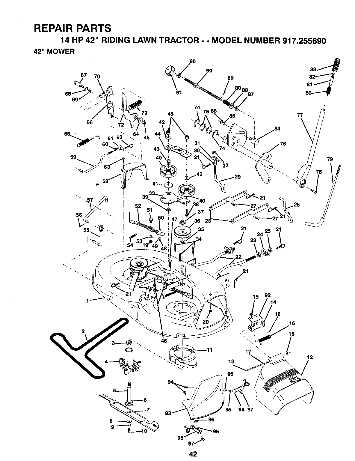
REPAIR PARTS
14 HP 42" RIDING LAWN TRACTOR - - MODEL NUMBER 917.255690
67 70
42" MOWER
43
51
35
34
79
!
19 92
14
2
17
13
96
95 98 97
18
16
15
12
42
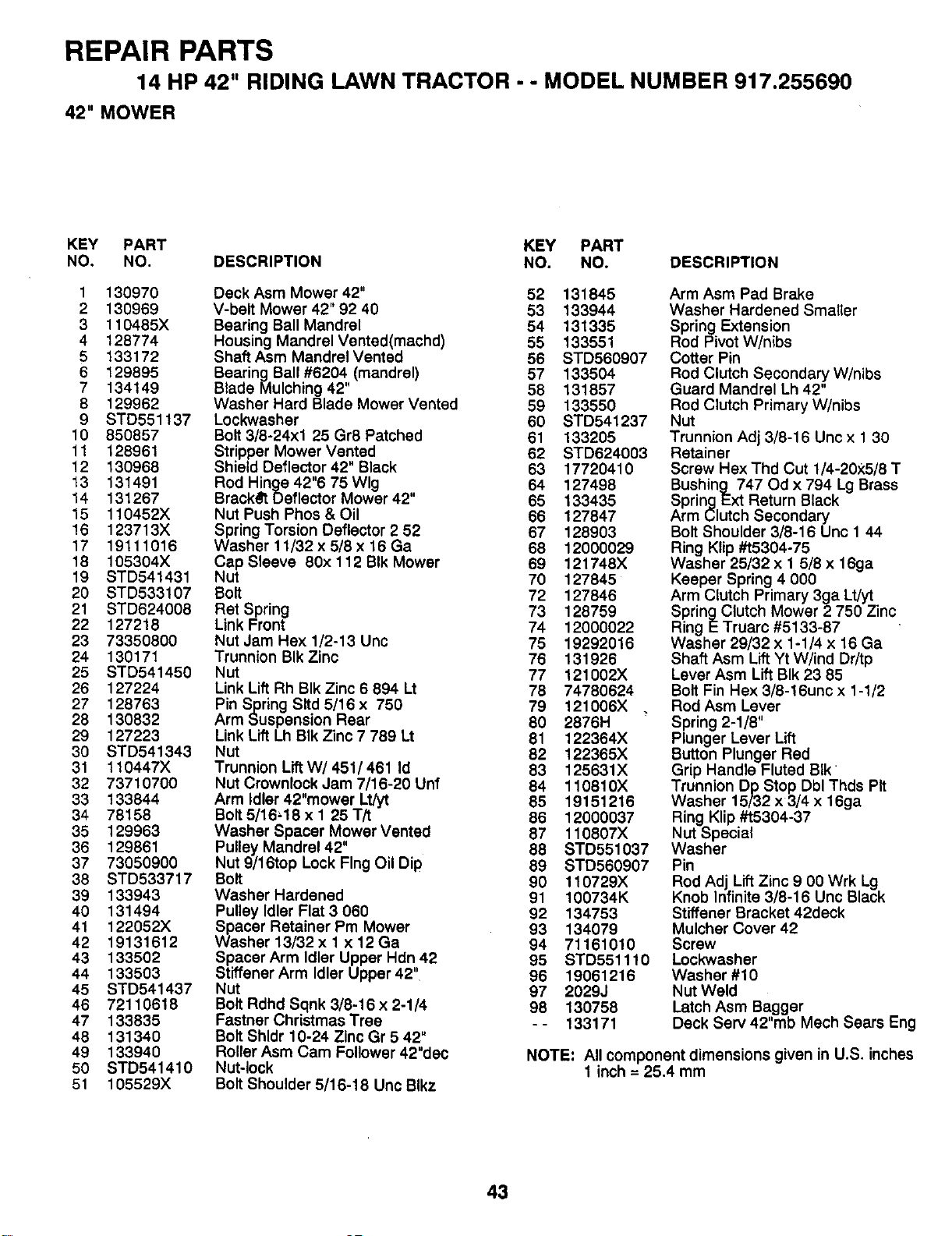
REPAIR PARTS
14 HP 42" RIDING LAWN TRACTOR - - MODEL NUMBER 917.255690
42" MOWER
KEY PART KEY PART
NO. NO. DESCRIPTION NO. NO. DESCRIPTION
1 130970
2 130969
3 110485X
4 128774
5 133172
6 129895
7 134149
8 129962
9 STD551137
10 850857
11 128961
12 130968
13 131491
14 131267
15 110452X
16 123713X
17 19111016
18 105304X
19 STD541431
20 STD533107
21 STD624008
22 127218
23 73350800
24 130171
25 STD541450
26 127224
27 128763
28 130832
29 127223
30 STD541343
31 110447X
32 73710700
33 133844
34 78158
35 129963
36 129861
37 73050900
38 STD533717
39 133943
40 131494
41 122052X
42 19131612
43 133502
44 133503
45 STD541437
46 72110618
47 133835
48 131340
49 133940
50 STD541410
51 105529X
Deck Asm Mower 42" 52 131845
V-belt Mower 42" 92 40 53 133944
Bearing Ball Mandrel 54 131335
Housing MandreIVented(machd) 55 133551
Shaft Asm Mandrel Vented 56 STD560907
Bearing Ball #6204 (mandrel) 57 133504
Blade Mulching 42" 58 131857
Washer Hard Blade Mower Vented 59 133550
Lockwasher 60 STD541237
Bolt 3/8-24xl 25 Gr8 Patched 61 133205
Stripper Mower Vented 62 STD624003
Shield Deflector 42" Black 63 17720410
Rod Hinge 42"6 75 Wig 64 127498
BrackSt Deflector Mower 42" 65 133435
Nut Push Phos & Oil 66 127847
Spring Torsion Deflector 2 52 67 128903
Washer 11/32 x 5/8 x 16 Ga 68 12000029
Cap Sleeve 80x 112 BIk Mower 69 121748X
Nut 70 127845
Bolt 72 127846
Ret Spring 73 128759
Link Front 74 12000022
Nut Jam Hex 1/2-13 Unc 75 19292016
Trunnion BIk Zinc 76 131926
Nut 77 121002X
Link Lift Rh BIk Zinc 6 894 Lt 78 74780624
Pin Spring Sltd 5/16 x 750 79 121006X
Arm Suspension Rear 80 2876H
Link Lift Lh BIk Zinc 7 789 Lt 81 122364X
Nut 82 122365X
Trunnion LiftW/ 451/ 461 Id 83 125631X
Nut Crownlock Jam 7/16-20 Unf 84 110810X
Arm Idler 42"mower Lt/yt 85 19151216
Bolt 5/16=18 x 1 25 T/t 86 12000037
Washer Spacer Mower Vented 87 110807X
Pulley Mandrel 42" 88 STD551037
Nut 9/16top Lock Flng Oil Dip 89 STD560907
Bolt 90 110729X
Washer Hardened 91 100734K
Pulley Idler Flat 3 060 92 134753
Spacer Retainer Pm Mower 93 134079
Washer 13/32 x 1 x 12 Ga 94 71161010
Spacer Arm Idler Upper Hdn 42 95 STD551110
Stiffener Arm Idler Upper 42" 96 19061216
Nut 97 2029J
Bolt Rdhd Sqnk 3/8-16 x 2-1/4 98 130758
Fastner Christmas Tree - - 133171
Bolt Shldr 10-24 Zinc Gr 5 42"
Roller Asm Cam Follower 42"dec
Nut-lock
Bolt Shoulder 5/16-18 Unc Blkz
Arm Asm Pad Brake
Washer Hardened Smaller
Spring Extension
Rod Pivot W/nibs
Cotter Pin
Rod Clutch Secondary W/nibs
Guard Mandrel Lh 42"
Rod Clutch Primary W/nibs
Nut
Trunnion Adj 3/8-16 Unc x 1 30
Retainer
Screw Hex Thd Cut 1/4-20x5/8 T
Bushing 747 Od x 794 Lg Brass
Spring Ext Return Black
Arm Clutch Secondary
Bolt Shoulder 3/8-16 Unc 1 44
Ring Klip #t5304-75
Washer 25/32 x 1 5/8 x 16ga
Keeper Spring 4 000
Arm Clutch Primary 3ga Lt/yt
Spring Clutch Mower 2 750 Zinc
Ring E Truarc #5133-87
Washer 29/32 x 1-1/4 x 16 Ga
Shaft Asm Lift Yt W/ind Dr/tp
Lever Asm Lift BIk 23 85
Bolt Fin Hex 3/8-16unc x 1-1/2
Rod Asm Lever
Spring 2-1/8"
Plunger Lever Lift
Button Plunger Red
Grip Handle Fluted BIk
Trunnion Dp Stop Dbl Thds Pit
Washer 15/32 x 3/4 x 16ga
Ring Klip #t5304-37
Nut Special
Washer
Pin
Rod Adj Lift Zinc 9 00 Wrk Lg
Knob Infinite 3/8-16 Unc Black
Stiffener Bracket 42deck
Mulcher Cover 42
Screw
Lockwasher
Washer #10
Nut Weld
Latch Asm Bagger
Deck Sew 42"mb Mech Sears Eng
NOTE: All component dimensions given in U.S. inches
1 inch = 25.4 mm
43
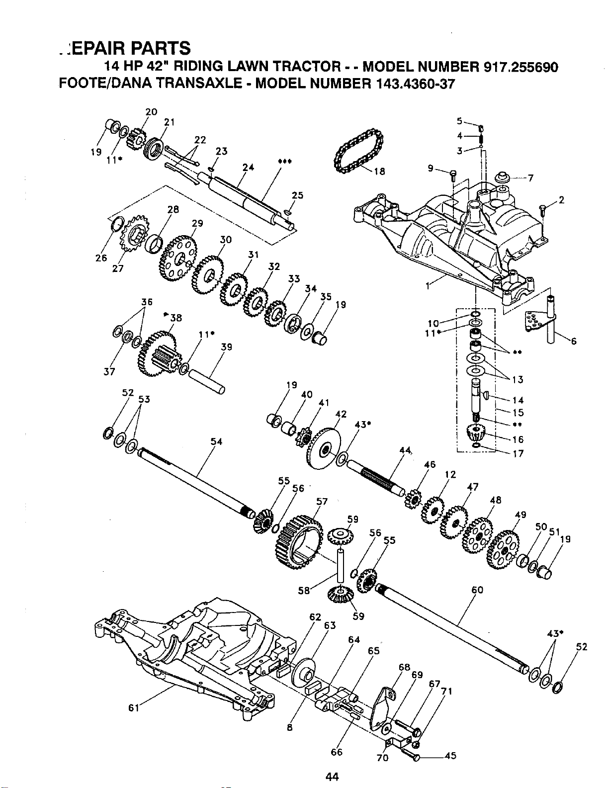
.:EPAIR PARTS
14 HP 42" RIDING LAWN TRACTOR. - MODEL NUMBER 917.255690
FOOTE/DANA TRANSAXLE - MODEL NUMBER 143.4360-37
19
26
2O
21
22 _ 24 O18
23
27
37
52
35
36 19
53
39
54
19
40
41
42
45"
55
56'
57
59
55
46
12
47
48
49
19
6O
62
63
59
64
65 +
68
69
7O
52
44
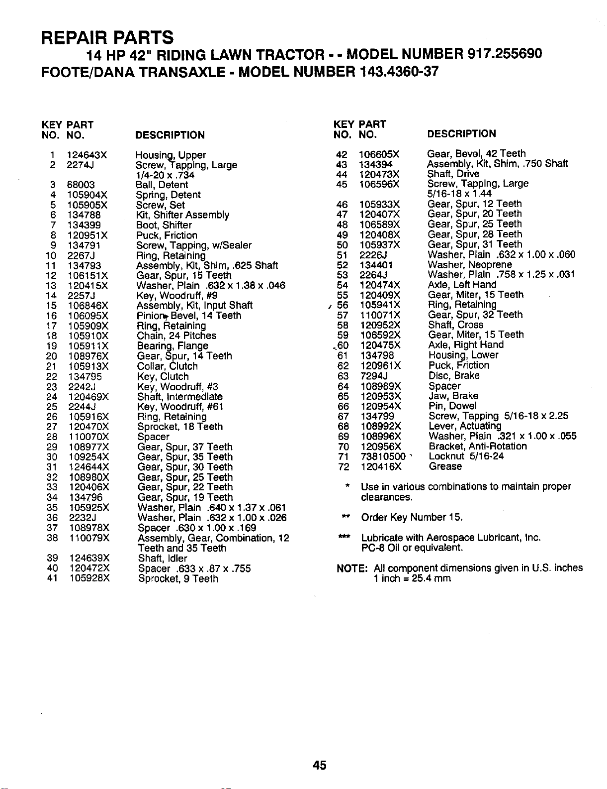
REPAIR PARTS
14 HP 42" RIDING LAWN TRACTOR - - MODEL NUMBER 917.255690
FOOTE/DANA TRANSAXLE - MODEL NUMBER 143.4360-37
KEY PART KEY PART
NO. NO. DESCRIPTION NO. NO. DESCRIPTION
1 124643X Housing, Upper 42
2 2274J Screw, Tapping, Large 43
1/4-20 x .734 44
3 68003 Ball, Detent 45
4 105904X Spring, Detent
5 105905X Screw, Set 46
6 134788 Kit, Shifter Assembly 47
7 134399 Boot, Shifter 48
8 120951X Puck, Friction 49
9 134791 Screw, Tapping, w/Sealer 50
10 2267J Ring, Retaining 51
11 134793 Assembly, Kit, Shim, .625 Shaft 52
12 106151X Gear, Spur, 15 Teeth 53
13 120415X Washer, Plain .632 x 1.38 x .046 54
14 2257J Key, Woodruff, #9 55
15 106846X Assembly, Kit, Input Shaft s 56
16 106095X Pinion_ Bevel, 14 Teeth 57
17 105909X Ring, Retaining 58
18 105910X Chain, 24 Pitches 59
19 105911X Bearing, Flange ..60
20 108976X Gear, Spur, 14 Teeth 61
21 105913X Collar, Clutch 62
22 134795 Key, Clutch 63
23 2242J Key, Woodruff, #3 64
24 120469X Shaft, Intermediate 65
25 2244J Key, Woodruff, #61 66
26 105916X Ring, Retaining 67
27 120470X Sprocket, 18 Teeth 68
28 110070X Spacer 69
29 108977X Gear, Spur, 37 Teeth 70
30 109254X Gear, Spur, 35 Teeth
31 124644X Gear, Spur, 30Teeth
32 108980X Gear, Spur, 25 Teeth
33 120406X Gear, Spur, 22 Teeth
34 134796 Gear, Spur, 19 Teeth
35 105925X Washer, Plain .640 x 1.37 x .061
36 2232J Washer, Plain .632 x 1.00 x .026
37 108978X Spacer .630 x 1.00 x .169
38 110079X Assembly, Gear, Combination, 12
Teeth and 35 Teeth
Shaft, Idler
Spacer .633 x .87 x .755
Sprocket, 9 Teeth
39 124639X
40 120472X
41 105928X
71
72
106605X
134394
120473X
106596X
105933X
120407X
106589X
120408X
105937X
2226J
134401
2264J
120474X
120409X
105941X
110071X
120952X
106592X
120475X
134798
120961X
7294J
108989X
120953X
120954X
134799
108992X
108996X
120956X
73810500 _
120416X
Gear, Bevel, 42 Teeth
Assembly, Kit, Shim, .750 Shaft
Shaft, Drive
Screw, Tapping, Large
5/16-18 x 1.44
Gear, Spur, 12 Teeth
Gear, Spur, 20 Teeth
Gear, Spur, 25 Teeth
Gear, Spur, 28 Teeth
Gear, Spur, 31 Teeth
Washer, Plain .632 x 1.00 x .060
Washer, Neoprene
Washer, Plain .758 x 1.25 x .031
Axle, Left Hand
Gear, Miter, 15 Teeth
Ring, Retaining
Gear, Spur, 32 Teeth
Shaft, Cross
Gear, Miter, 15 Teeth
Axle, Right Hand
Housing, Lower
Puck, Friction
Disc, Brake
Spacer
Jaw, Brake
Pin, Dowel
Screw, Tapping 5/16-18 x 2.25
Lever, Actuating
Washer, Plain .321 x 1.00 x .055
Bracket, Anti-Rotation
Locknut 5/16-24
Grease
* Use in various combinations to maintain proper
clearances.
** Order Key Number 15.
*** Lubricate with Aerospace Lubricant, Inc.
PC-8 Oil or equivalent.
NOTE: All component dimensions given in U.S. inches
1 inch = 25.4 mm
45
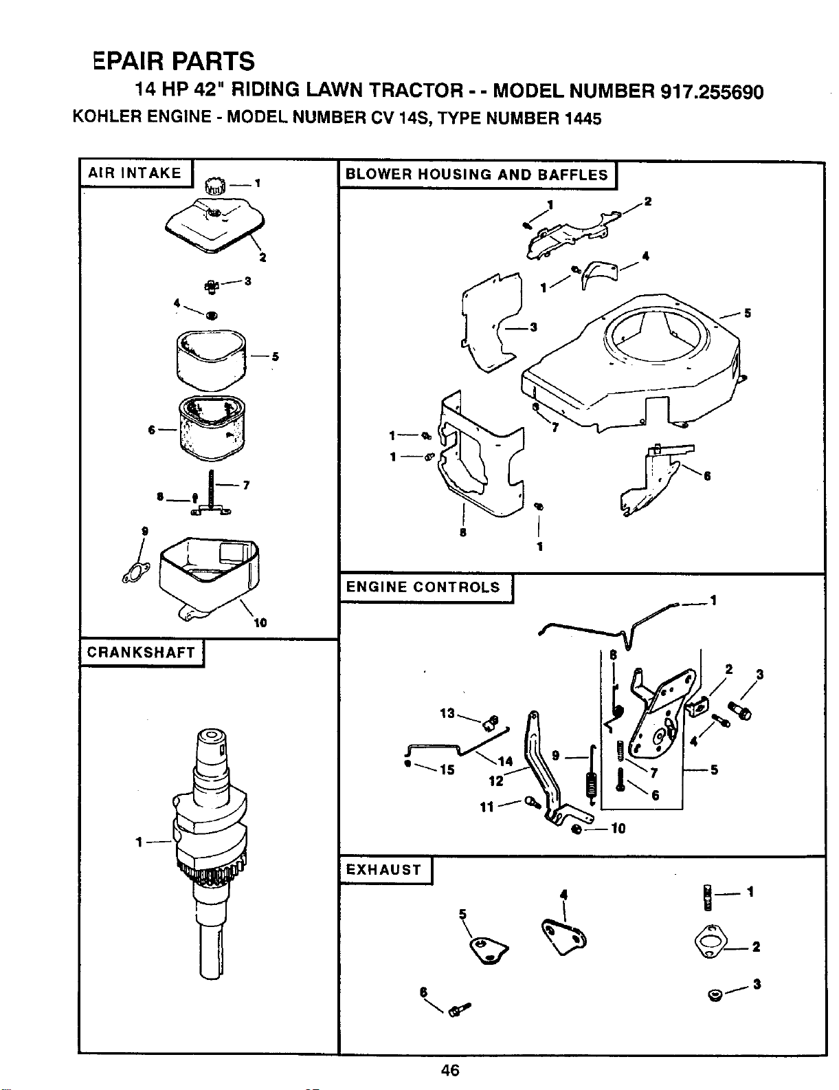
EPAIR PARTS
14 HP 42" RIDING LAWN TRACTOR - - MODEL NUMBER 917.255690
KOHLER ENGINE- MODEL NUMBER CV 14S, TYPE NUMBER 1445
AIR INTAKE I t_--1
2
9
lO
CRANKSHAFT J
BLOWER HOUSING AND BAFFLES I
I
1
ENGINE CONTROLS I
2 3
/
EXHAUST I
46
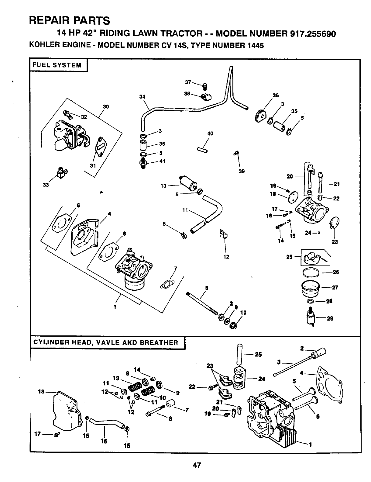
REPAIR PARTS
14 HP 42" RIDING LAWN TRACTOR - - MODEL NUMBER 917.255690
KOHLER ENGINE- MODEL NUMBER CV 14S, TYPE NUMBER 1445
FUEL SYSTEM I
31
33
6
3O
1
7
CYLINDER HEAD, VAVLE AND BREATHER I
14
9
13.
9
-7
23
21
20 --.__
36
19-__ 21
14 23
--26
27
--25
--29
47
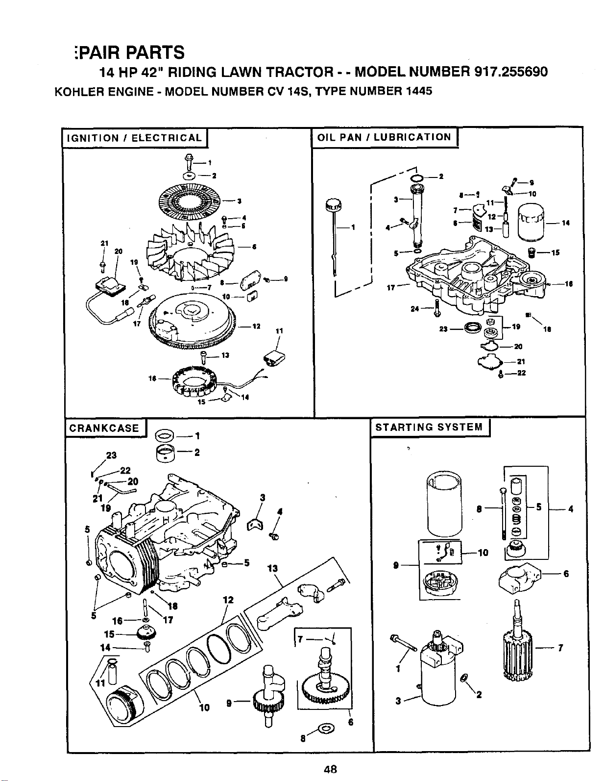
[PAIR PARTS
14 HP 42" RIDING LAWN TRACTOR - - MODEL NUMBER 917.255690
KOHLER ENGINE- MODEL NUMBER CV 14S, TYPE NUMBER 1445
IGNITION I ELECTRICAL I
O--=
21 20 19 --$
13
OIL PAN I LUBRICATION I
..11
J _--= p__g
',
STARTING SYSTEM I
1
3
_7
48
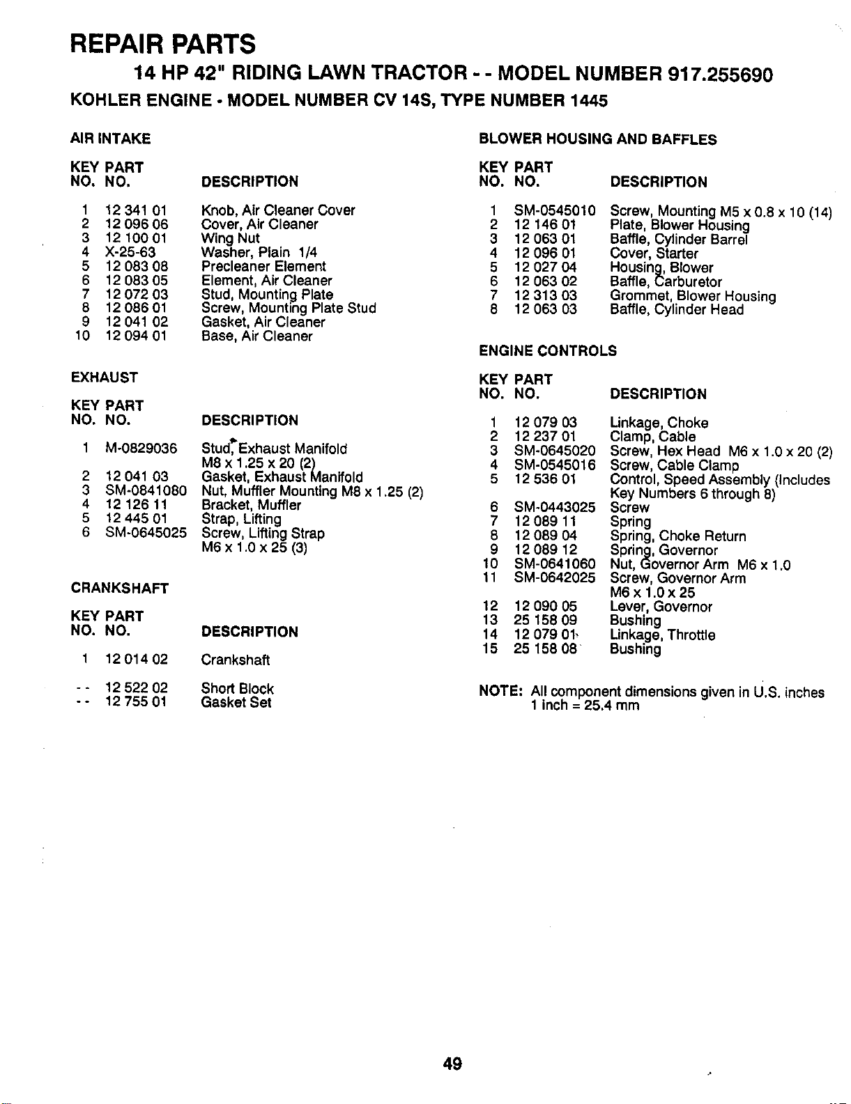
REPAIR PARTS
14 HP 42" RIDING LAWN TRACTOR - - MODEL NUMBER 917.255690
KOHLER ENGINE - MODEL NUMBER CV 14S, TYPE NUMBER 1445
AIR INTAKE BLOWER HOUSING AND BAFFLES
KEY PART KEY PART
NO. NO. DESCRIPTION NO. NO. DESCRIPTION
1 12 341 01 Knob, Air Cleaner Cover 1 SM-0545010
2 12 096 06 Cover, Air Cleaner 2 12 146 01
3 12 100 01 Wing Nut 3 1206301
4 X-25-63 Washer, Plain 1/4 4 12 096 01
5 12 083 08 Precleaner Element 5 12 027 04
6 12 083 05 Element, Air Cleaner 6 12 063 02
7 12 072 03 Stud, Mountin_gPlate 7 12 313 03
8 12 086 01 Screw, Mount=rigPlate Stud 8 12 063 03
9 12 041 02 Gasket, Air Cleaner
10 12 094 01 Base, Air Cleaner
ENGINE CONTROLS
EXHAUST KEY PART
NO. NO.
KEY PART
NO. NO.
1 M-0829036
DESCRIPTION
Stud,_Exhaust Manifold
M8 x 1.25 x 20 (2)
Gasket, Exhaust Manifold
Nut, Muffler Mounting M8 x 1.25 (2)
Bracket, Muffler
Strap, Liffing
Screw, Lifting Strap
M6 x 1.0 x 25 (3)
DESCRIPTION
Crankshaft
Short Block
Gasket Set
2 12 041 03
3 SM-0841080
4 12 126 11
5 12 445 01
6 SM-0645025
Screw, Mounting M5 x 0.8 x 10 (14)
Plate, Blower Housing
Baffle, Cylinder Barrel
Cover, Starter
Housing, Blower
Baffle, Carburetor
Grommet, Blower Housing
Baffle, Cylinder Head
CRANKSHAFT
KEY PART
NO. NO.
1 1201402
- - 12 522 02
-- 1275501
DESCRIPTION
1 12 07903
2 12 237 01
3 SM-0645020
4 SM-0545016
5 12 536 01
6 SM-0443025
7 12 089 11
8 12 089 04
9 12 089 12
10 SM-0641060
11 SM-0642025
12 12 090 05
13 25 158 09
14 12 07901_
15 25 158 08
Linkage, Choke
Clamp, Cable
Screw, Hex Head M6 x 1.0 x 20 (2)
Screw, Cable Clamp
Control, Speed Assembly (Includes
Key Numbers 6 through 8)
Screw
Spring
Spring, Choke Return
Spring, Governor
Nut, Governor Arm M6 x 1.0
Screw, Governor Arm
M6x 1.0x25
Lever, Governor
Bushing
Linkage, Throttle
Bushing
NOTE: AII componentdimensions givenin U.S. inches
1 inch = 25.4mm
49

PAIR PARTS
14 HP 42" RIDING LAWN TRACTOR - - MODEL NUMBER 917.255690
KOHLER ENGINE- MODEL NUMBER CV 14S, TYPE NUMBER 1445
FUEL SYSTEM
KEY PART
NO. NO. DESCRIPTION
CYLINDER HEAD, VALVE AND BREATHER
KEY PART
NO. NO. DESCRIPTION
12 853 08
2 X-22-11
3 25 237 02
4 12 265 01
5 X-426-9
6 12041 01
7 12041 02
8 M-0629122
9 X-25-63
10 SM-0641060
11 52 353 22
12 4715401
13 25 050 02
14 12 368 01
15 1208909
16 12 086 04
17 12 089 09
18 1214603
19 25 086 27
2O 12 144 09
21 1214408
22 12 089 10
23 12 146 02
24 1233701
25 12 757 02
26 12 041 05
27 1210401
28 12 041 06
29 12 086 05
30 12 559 01
31 25 041 09
32 SM-0645020
33 25 155 02
34 12 123 01
35 12 353 01
36 1231301
37 SM-0545010
38 12 154 01
39 12 086 07
40 12431 01
41 X-380-1
Kit, Carburetor w/Gaskets t 12 318 01
(Includes Key Numbers 6, 7, and 2 12 351 01
14-29, and all Kits marked *) 3 12 411 01
Washer, Star 1/4 4 12 041 04
Clamp, Hose (2) 5 12 017 01
Deflector, Heat 12 017 02
Clamp, Hose (4) 6 12 016 01
Gasket, Carburetor (2) 12 016 02
Gasket, Air Cleaner 7 12 112 04
Stud, Carburetor M6 x 1.0 x 110 (2) 8 M-1040080
Washer, Plain 1/4
Nut, Carburetor M6 x 1.0 (2) 9 52 018 01
FuelLine 10 1208915
Clip, Cable 11 1217301
Filter, Fuel 12 12 755 03
Neettle, Idle 13 12 089 01
Spring, Idle Speed 14 12 032 02
Screw, Idle Speed Adjust 15 X-426-9
Spring, Idle Fuel 16 12 326 03
Plate, Throttle 17 SM-0645020
Screw, Throttle Plate (2)
Shaft, Throttle with Lever and Seal 18 12 096 07
Shaft, Choke 19 SM-0545010
Spring, Choke Return
Plate, Choke 20 12 018 01
Jet, Main 21 1240201
Kit, Float 22 SM-0642025
Gasket, Bowl
Bowl, Fuel 23 12 186 01
Gasket, Bowl Retainer Screw 24 12 126 05
Screw, Fuel Bowl 25 12 144 03
Kit, Fuel Pump (Includes Key #31)
Gasket, Fuel Pump
Screw, Fuel Pump M6 x 1.0 x 20 (2)
Connector, Hose
Line, Fuel, Metal
Line, Fuel, Rubber (2)
Grommet, Fuel Line
Screw, Fuel Line Clamp
Clamp, Fuel Line
Screw, Ground Wire
Sleeve, Insulating
Connector, Hose
NOT ILLUSTRATED
12 757 01 * Kit, Carburetor Repair
12 755 09 * Kit, High Altitude Jet
12 435 02 * Solenoid Assembly, Fuel
12 518 05 Lead, Solenoid, Black, 5", 14
Gauge Uninsulated Push-On Tabs
41 518 34 Lead, Ground, Green, 5", 18 Gauge
Insulated Grip Barrel Eyelets
Head, Cylinder
Lifter, Valve (2)
Rod, Push (2)
Gasket, Cylinder Head
Valve, Intake, Standard Size
Valve, Intake .25" oversize
Valve, Exhaust, Standard
Valve, Exhaust .25" oversize
Spacer, Head Bolt Exhaust Port
Screw, Cylinder Head
M10 x 1.5 x 80 (5)
Retainer, Spring (2)
Spring, Exhaust Valve, Green
Cap, Valve Spring (2)
Kit, Retainer (2)
Spring, Intake Valve
Seal, Valve Stem
Clamp, Hose (2)
Hose, Breather
Screw, Valve Cover
M6 x 1.0 x 20 (3)
Cover, Valve with Nipple
Screw, Breather Reed Retainer
M5x0.8x 1
Retainer, Breather Reed
Reed, Breather
Screw, Rocker Bridge
M6 x 1.0 x 25 (2)
Arm, Rocker (2)
Bridge, Rocker Arm
Shaft, Rocker Arm
NOT ILLUSTRATED
12 755 02 Kit, Cylinder Head
NOTE: All component dimensions given in U.S. inches
1 inch = 25.4 mm
5O
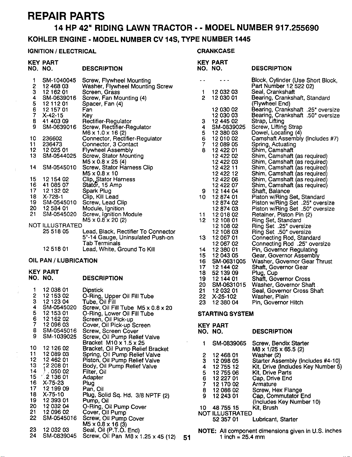
REPAIR PARTS
14 HP 42" RIDING LAWN TRACTOR - - MODEL NUMBER 917.255690
KOHLER ENGINE - MODEL NUMBER CV 14S, TYPE NUMBER 1445
IGNITION / ELECTRICAL CRANKCASE
KEY PART KEY PART
NO. NO. DESCRIPTION NO. NO. DESCRIPTION
1 SM-1040045 Screw, Flywheel Mounting --
2 12 468 03 Washer, Flywheel Mounting Screw
3 12 162 01 Screen, Grass 1
4 SM-0639016 Screw, Fan Mounting (4) 2
5 12 112 01 Spacer, Fan (4)
6 12 157 01 Fan
7 X-42-15 Key
8 41 403 09 Rectifier-Regulator
9 SM-0639016 Screw, Rectifier-Regulator
10 236602
11 236473
12 12 025 01
13 SM-0544025
14 SM-0545010
15 12 154 02
16 41 085 07
17 12 132 02
18 X-728-1
19 SM-0545010
20 12 584 01
21 SM-0545020
M6x 1.0x 16 (2)
Connector, Rectifier-Regulator
Connector, 3 Contact
Flywheel Assembly
Screw, Stator Mounting
M5 x 0.8 x 25 (4)
Screw, Stator Harness Clip
M5 x 0.8 x 10
Clip,,Stator Harness
Stat(_r, 15 Amp
Spark Plug
Clip, Kill Lead
Screw, Lead Clip
Module, Ignition
Screw, Ignition Module
M5 x 0.8 x 20 (2)
NOT ILLUSTRATED
25 518 05 Lead, Black, Rectifier To Connector
5"-14 Gauge, Uninsulated Push-on
Tab Terminals
12 518 01 Lead, White, Ground To Kill
OIL PAN / LUBRICATION
KEY PART
NO. NO. DESCRIPTION
1 12 038 01
2 12 153 02
3 12 123 04
4 SM-0545020
5 12 153 01
6 12 162 02
7 12 096 03
8 SM-0545016
9 SM-1039025
10 12126 02
11 12 089 03
12 12 462 01
13 ;2 208 01
14 _. 05O 02
15 _2 136 01
16 X-75-23
17 12199 09
18 X-75-10
19 12 393 01
20 12 032 04
21 12 096 02
22 SM-0545016
23 12 032 93
24 SM-0839045
Dipstick
O-Ring, Upper Oil Fill Tube
Tube, Oil Fill
Screw, Oil Fill Tube M5 x 0.8 x 20
O-Ring, Lower Oil Fill Tube
Screen, Oil Pick-up
Cover, Oil Pick-up Screen
Screw, Screen Cover
Screw, Oil Pump Relief Valve
Bracket M10 x 1.5 x 25
Bracket, Oil Pump Relief Bracket
Spring, Oil Pump Relief Valve
Piston, Oil Pump Relief Valve
Body, Oil Pump Relief Valve
Filter, Oil
Adapter
Plug
Pan, Oil
Plug, Solid Sq. Hal. 3/8 NPTF (2)
Pump, Oil
O-Ring, Oil Pump Cover
Cover, Oil Pump
Screw, Oil Pump Cover
M5 x 0.8 x t6 (3)
Seal, Oil (P.T.O. End)
Screw, Oil Pan M8 x 1.25 x 45 (12)
12 032 03
12 030 01
12 030 02
12 030 03
3 12 445 02
4 SM-0839025
5 12 380 03
6 12 010 02
7 12 089 05
8 12 422 01
12 422 02
12 422 03
!2 422 11
12 422 12
12 422 06
12 422 07
9 12 144 04
10 12 874 Ot
12 874 02
12 874 03
11 12 018 02
12 12 108 01
12108 02
12108 03
13 12 067 01
12 067 02
14 12 380 01
15 12 043 05
16 SM-0631005
17 12 144 02
18 52 13909
19 12 144 01
20 SM-0631015
21 12 032 01
22 X-25-102
23 12 380 04
Block, Cylinder (Use Short Block,
Part Number 12 522 02)
Seal, Crankshaft
Bearing, Crankshaft, Standard
(Flywheel End)
Bearing, Crankshaft .25" oversize
Bearing, Crankshaft .50" oversize
Strap, Lifting
Screw, Lifting Strap
Dowel, Locating (4)
Camshaft Assembly (Includes #7)
Spring, Actuating
Shim, Camshaft
Shim, Camshaft (as required)
Shim, Camshaft (as required)
Shim, Camshaft (as required)
Shim, Camshaft (as required)
Shim, Camshaft (as required)
Shim, Camshaft (as required)
Shaft, Balance
Piston w/Ring Set, Standard
Piston w/Ring Set .25" oversize
Piston w/Ring Set .50" oversize
Retainer, Piston Pin (2)
Ring Set, Standard
Ring Set .25" oversize
Ring Set .50" oversize
Connecting Rod, Standard
Connecting Rod .25" oversize
Pin, Governor Regulating
Gear, Governor Assembly
Washer, Governor Gear Thrust
Shaft, Governor Gear
Plug, Cup
Shaft, Governor Cross
Washer, Governor Shaft
Seal, Governor Cross Shaft
Washer, Plain
Pin, Governor Hitch
STARTING SYSTEM
KEY PART
NO. NO. DESCRIPTION
1 SM-0839065
2
3
4
5
6
7
8
9
12 468 01
12 098 05
12 755 12
12 755 06
12 227 01
12170 02
12 086 02
12 243 01
10 48 755 15
NOT
Screw, Bendix Starter
M8 x 1/25 x 65.5 (2)
Washer (2)
Starter Assembly (Includes #4-10)
Kit, Drive (Includes Key Number 5)
Kit, Drive Parts
Cap, Drive End
Armature
Screw, Hex Flange
Cap, Commutator End
(Includes Key Number 10)
Kit, Brush
ILLUSTRATED
52 357 01 Lubricant, Starter
NOTE: All component dimensions given in U.S. inches
51 1 inch = 25.4 mm

SERVICE NOTES
52

SERVICE NOTES
53

SERVICE NOTES
54

SUGGESTED GUIDE FOR SIGHTING SLOPES FOR SAFE OPERATION
OI
O1
ONLY RIDE UP AND DOWN HILL,
NOT ACROSS HILL
SIGHT AND HOLD THIS LEVEL WITH
SKY LINE OR TREE.
15 ° MAX.
Operate your Tractor up and down the face of slopes (not.
greater than 15°), never across the face. Make turns gradu
ally to prevent tipping or loss of control. Exercise extreme
caution when changing direction on slopes.
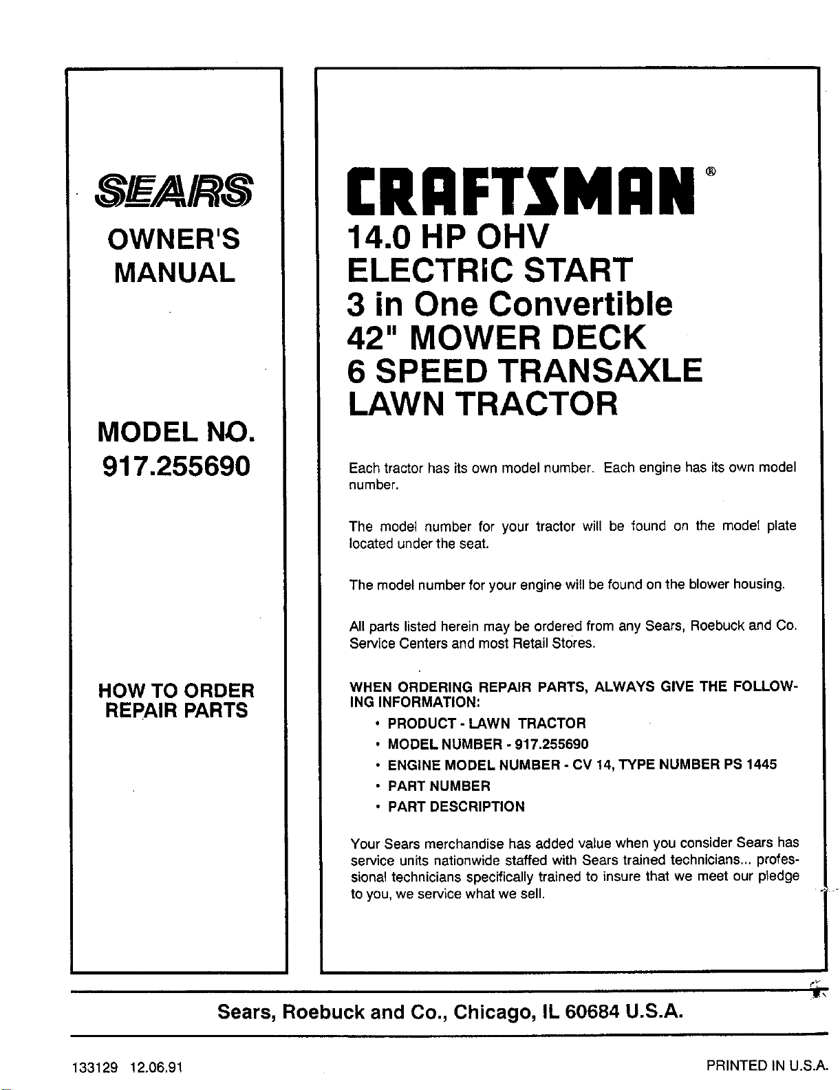
SE_AIRS
OWNER'S
MANUAL
MODEL NO.
917.255690
HOW TO ORDER
REPAIR PARTS
[RIIFTZMRN +
14.0 HP OHV
ELECTRIC START
3 in One Convertible
42" MOWER DECK
6 SPEED TRANSAXLE
LAWN TRACTOR
Each tractor has its own model number. Each engine has itsown model
number.
The model number for your tractor will be found on the model plate
located under the seat.
The model number for your engine will be found on the blower housing.
All parts listed herein may be ordered from any Sears, Roebuck and Co.
Service Centers and most Retail Stores.
WHEN ORDERING REPAIR PARTS, ALWAYS GIVE THE FOLLOW-
ING INFORMATION:
• PRODUCT-LAWN TRACTOR
• MODEL NUMBER - 917.255690
• ENGINE MODEL NUMBER - CV 14, TYPE NUMBER PS 1445
• PART NUMBER
• PART DESCRIPTION
Your Sears merchandise has added value when you consider Sears has
service units nationwide staffed with Sears trained technicians., profes-
sional technicians specifically trained to insure that we meet our pledge
to you, we service what we sell.
j_
Sears, Roebuck and Co., Chicago, IL 60684 U.S.A.
133129 12.06.91 PRINTED IN U.S.A.


